

Pioneer DEH-P900HDD User Manual [en, de, es, fr, it]
6
1
DEH-P900HDD
11
12
9
10
8
7
13
14
15
MANUEL D’INSTALLATION
2
182
53
30°
3
4
5
This product conforms to new cord colors.
Los colores de los cables de este producto se conforman con un nuevo código de colores.
Dieses Produkt entspricht den neuen kabelfarben.
Le code de couleur des câbles utilisé pour ce produit
est nouveau.
INSTALLATION MANUAL
Questo prodotto è conforme ai nuovi codici colori.
De kleuren van de snoeren van dit toestel zijn gewijzigd.
Printed in Japan
Imprimé au Japon
<CRD3471-A> EW
<KMMUF/01K00000>
Fig. 1
Abb. 1
Afb. 1
Fig. 2
Abb. 2
Afb. 2
Fig. 3
Abb. 3
Afb. 3
Fig. 4
Abb. 4
Afb. 4
Fig. 5
Abb. 5
Afb. 5
Fig. 6
Abb. 6
Afb. 6
Fig. 7
Abb. 7
Afb. 7
Fig. 8
Abb. 8
Afb. 8
Fig. 9
Abb. 9
Afb. 9
Fig. 10
Abb. 10
Afb. 10
Fig. 11
Abb. 11
Afb. 11
Fig. 12
Abb. 12
Afb. 12

Installation <ENGLISH>
Note:
• Before finally installing the unit, connect the
wiring temporarily, making sure it is all connected up properly, and the unit and the system work
properly.
• Use only the parts included with the unit to
ensure proper installation. The use of unauthorized parts can cause malfunctions.
• Consult with your nearest dealer if installation
requires the drilling of holes or other modifications of the vehicle.
• Install the unit where it does not get in the driver’s way and cannot injure the passenger if there
is a sudden stop, like an emergency stop.
• The semiconductor laser will be damaged if it
overheats, so don’t install the unit anywhere hot
— for instance, near a heater outlet.
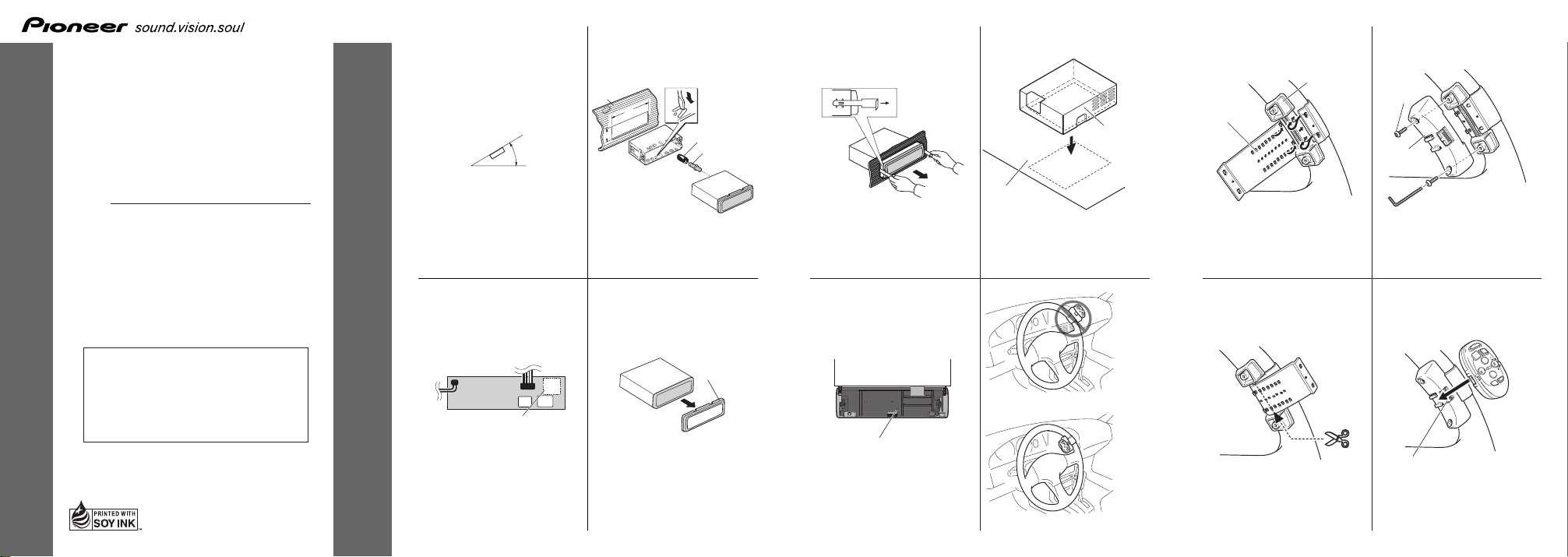
• If installation angle exceeds 30° from horizontal,
the unit might not give its optimum performance.
(Fig. 1)
• This unit and the GPS antenna of the navigation
unit should be set as far apart as possible. If they
are too close, this unit and the navigation unit
may not operate correctly.
• Do not install the power box near doors where
rainwater could splash onto it.
• As the power box can heat up, it should never be
installed in the following locations:
– where it could come into contact with car
wiring or equipment
– where it would easily come into contact with
passengers.
• This unit must be installed after pulling the autoequalizing mike jack out of the console box, so
that the mike can be plugged in or pulled out
even after this unit has been installed.
• The cords must not cover up the area shown in
Fig. 2. This is so the amplifiers can radiate freely.
1. Do not close this area.
Installation with the rubber bush
(Fig. 3)
2. Dashboard
3. Holder
After inserting the holder into the dashboard,
then select the appropriate tabs according to the
thickness of the dashboard material and bend
them.
(Install as firmly as possible using the top and
bottom tabs. To secure, bend the tabs 90
degrees.)
4. Rubber bush
5. Screw
Removing the Unit (Fig. 4) (Fig. 5)
6. Frame
Pull out to remove the frame. (When reattaching
the frame, point the side with a groove downwards and attach it.)
7. Insert the supplied extraction keys into the unit,
as shown in the figure, until they click into place.
Keeping the keys pressed against the sides of the
unit, pull the unit out.
About the fixing screws for the
front panel (Fig. 6)
If you do not operate the Detaching and
Replacing the Front Panel Function, use the supplied fixing screws and fix the front panel to this
unit.
8. Fixing screw
Installing the power box (Fig. 7)
The power box has velcro tape on the underside
to secure it to the car mat.
• Wipe the surface thoroughly before affixing the
velcro tape.
9. Velcro tape
10.Car mat
Instalación <ESPAÑOL>
Nota:
• Antes de finalmente instalar la unidad, conecte el
cableado temporalmente y asegúrese de que todo
esté conectado correctamente y que la unidad y
el sistema funcionan debidamente.
• Utilice sólo las piezas que se incluyen con esta
unidad para asegurar la instalación adecuada. El
uso de piezas no autorizadas podría causar fallos
de funcionamiento.
• Consulte con su distribuidor si la instalación
requiere del taladro de orificios u otras modificaciones del vehículo.
• Instale la unidad donde no alcance el espacio del
conductor, y donde no pueda dañar a los
pasajeros si sucediera un paro repentino, como
una detención de emergencia.
• El semiconductor láser se dañará si se sobrecalienta, por eso no instale la unidad en un lugar
caliente – por ejemplo, cerca de la salida de un
calefactor.
• Si el ángulo de la instalación excede los 30° del
lado horizontal, la unidad podría no brindar su
óptimo funcionamiento. (Fig. 1)
• Esta unidad y la antena GPS de la unidad de
navegación deben instalarse lo más alejadas posible. Si están muy cercas, podría producirse un
funcionamiento defectuoso de esta unidad y de la
unidad de navegación.
• No instale la unidad de potencia cerca de las
puertas, donde pueda quedar expuesta a la lluvia.
• Debido a que la caja de potencia podría alcanzar
altas temperaturas, no la instale nunca en los
lugares siguientes:
– donde pueda entrar en contacto con el conex-
ionado o con el equipo de la radio.
– donde pueda entrar fácilmente en contacto con
los pasajeros.
• El jack del micrófono para ecualización
automática deberá fijarse a esta unidad sacándolo
fuera de la consola, de manera que sea posible
conector o extraer el micrófono de la consola aun
después de instalar esta unidad.
• Los cordones no deben cubrir el área mostrada
en la Fig. 2. Esto es necesario para que los
amplificadores puedan radiar energía libremente.
1. No cierre este área.
Instalación con tope de goma
(Fig. 3)
2. Tablero de instrumentos
3. Soporte
Después de insertar el soporte en la tabla de
mandos, luego seleccione las orejetas apropiadas
según el grosor del material de la tabla de mandos y dóblelos.
(Instale lo más firme posible usando las lengüetas superior e inferior. Para fijar, doble las
lengüetas 90 grados.)
4. Tope de goma
5. Tornillo
Quitado de la unidad (Fig. 4) (Fig. 5)
6. Marco
Tire hacia afuera para extraer el marco. (Para la
fijación del marco, apunte el lado con ranura
hacia abajo.)
7. Inserte las herramientas de extracción suministradas en la unidad, como se indica en la figura,
hasta que se enganchen en su positión.
Tire de la unidad mientras mantiene las herramientas presionadas contra los lados de la
unidad.
Sobre los tornillos de fijación del
panel delantero (Fig. 6)
Si no desea utilizar la función de extracción y
colocación del panel delantero, utilice los tornillos de fijación suministrados y fije el panel
delantero a esta unidad.
8. Tornillos de fijación
Instalación de la caja de potencia
(Fig. 7)
La caja de potencia está provista de una cinta
Velcro en su parte inferior para poderla asegurar
a la alfombra del automóvil.
• Limpie a fondo toda la superficie antes de fijar la
cinta Velcro.
9. Cinta Velcro
10.Alfombra del automóvil
Einbau <DEUTSCH>
Hinweis:
• Schließen Sie vor dem Einbau die Leitungen
vorübergehend an und stellen Sie sicher, das alles
richtig angeschlossen ist und das Gerät und das
System einwandfrei arbeiten.
• Um einwandfreien Einbau zu gewährleisten, sollten nur die mit dem Gerät mitgelieferten Teile
verwendet werden. Bei Verwendung von NichtOriginalteilen kann es zu Funktionsstörungen
kommen.
• Wenden Sie sich an Ihren Fachhänlder, wenn
zum Einbau des Geräts Löcher gebohrt oder
andere Veränderungen an Ihrem Auto vorgenommen werden müssen.
• Bauen Sie das Gerät an einer Stelle ein, wo es
den Fahrer nicht behindert und den Beifahrer bei
plötzlichem Bremsen nicht verletzen an.
• Der Halbleiterlaser wird bei Überhitzung
beschädigt, bauen Sie das Gerät daher nicht an
einer Stelle ein, wo es heiß wird, z.B. nahe einer
Heizungsauslaßöffnung.
• Wenn der Einbauwinkel mehr als 30º von der
Horizontalen abweicht, kann es sein, daß das
Gerät nicht optimal arbeitet. (Abb. 1)
• Dieses Gerät und die GPS-Antenne der
Navigationseinheit sollten so weit wie möglich
von einander entfernt sein. Wenn Sie zu nahe an
einander sind, arbeiten dieses Gerät und die
Navigationseinheit möglicherweise nicht korrekt.
• Installieren Sie den Stromversorgungskasten
nicht in der Nähe einer Tür, wo er durch
Regenwasser nass werden kann.
• Da der Stromversorgungskasten heiß werden
kann, sollte er niemals an einem der folgenden
Orte installiert werden:
– Orte, an denen er in Kontakt mit der
Verdrahtung oder der Ausrüstung des Autos
kommen kann.
– Orte, an denen er leicht in Kontakt mit
Passagieren kommen kann.
• Dieses Gerät muss installiert werden, nachdem
der Anschluss für das Mikrofon mit automatischer Entzerrung aus dem Konsolenkasten gezogen
worden ist, damit das Mikrofon auch nach
Installation dieses Gerätes angeschlossen bzw.
abgezogen werden kann.
• Die Kabel dürfen nicht den in Abb. 2 gezeigten
Bereich bedecken, damit die Verstärker Wärme
frei abstrahlen können.
1. Diesen Bereich nicht abdecken.
Einbau mit der Gummibuchse
(Abb. 3)
2. Armaturenbrett
3. Halter
Den Halter in das Armaturenbrett einsetzen, dann
die der Dicke des Armaturenbretts entsprechenden Zungen auswählen und diese biegen.
(Mit Hilfe der Ansätze, oben und unten, so fest
wie möglich einsetzen. Zur Sicherung werden die
Ansätze 90 Grad gebogen.)
4. Gummibuchse
5. Schraube
Entnahme des Gerätes
(Abb. 4) (Abb. 5)
6. Rahmen
Herausziehen, um den Rahmen abzunehmen.
(Beim Wiederanbringen des Rahmens muß die
Seite mit der Nut nach unten weisen.)
7. Die mitgelieferten Ausziehschlüssel wie in der
Abbildung gezeigt bis zur Einrastposition in das
Gerät einsetzen. Die Schlüssel gegen die Seiten
des Geräts drücken und das Gerät herausziehen.
Befestigungsschrauben für die
Frontplatte (Abb. 6)
Wenn Sie die Funktion zum Abnehmen und
Auswechseln der Frontplatte nicht verwenden
wollen, so fixieren Sie die Frontplatte mit den
mitgelieferten Befestigungsschrauben an diesem
Gerät.
8. Befestigungsschraube
Installation des
Stromversorgungskastens (Abb. 7)
Der Stromversorgungskasten hat an der
Unterseite einen Klettverschlussstreifen (VelcroStreifen) zur Sicherung an der Bodenmatte.
• Wischen Sie die Oberfläche gründlich sauber,
bevor Sie den Velcro-Streifen aufkleben.
9. Velcro-Streifen
10.Bodenmatte
Installation <FRANÇAIS>
Remarque:
• Avant de finaliser l’installation de l’appareil,
connecter temporairement le câblage en s’assurant que tout est correctement connecté et que
l’appareil et le système fonctionnement correctement.
• Pour obtenir une bonne installation, n’utiliser que
les pièces de l’appareil. L’utilisation de pièces
non prévues risque de causer un mauvais fonctionnement.
• Consulter le concessionnaire le plus proche si
l’installation nécessite le percement de trous ou
toute autre modification du véhicule.
• Installer l’appareil à un endroit où il ne gêne pas
le conducteur et où il ne peut pas blesser les passagers en cas d’arrêt brusque, comme pendant un
arrêt d’urgence.
• Le laser semiconducteur sera endommagé en cas
de réchauffement excessif. Dans ce cas ne pas
installer l’appareil dans un endroit présentant une
température élevée, tel que sortie de chauffage.
• L’angle de l’installation, ne doit pas dépasser 30°
par rapport à l’horizontale, faute de quoi l’unité ne
fournira pas ses performances optimales. (Fig. 1)
• L’appareil et l’antenne GPS du module de navigation devront être éloignés au maximum l’un de
l’autre. S’ils sont trop près, l’appareil et le module de navigation risquent de ne pas fonctionner
correctement.
• N’installez pas le boîtier d’alimentation près des
portières, car l’eau de pluie pourrait gicler
dessus.
• Le boîtier d’alimentation risquant de chauffer, ne
l’installez jamais dans les endroits suivants:
– Là où il pourrait entrer en contact avec un fil
ou un instrument de la voiture
– Là où il pourrait facilement toucher les pas-
sagers.
• Il faudra installer l’appareil après avoir retiré la
prise de microphone à auto-égalisation du boîtier
de console, de façon à pouvoir toujours brancher
et débrancher le microphone après avoir installé
l’appareil.
• Les cordons ne doivent pas traverser la section
représentée à la Fig. 2, afin que les amplificateurs puissent rayonner librement.
1. Ne fermez pas cette section.
Installation avec une bague en
caoutchouc (Fig. 3)
2. Tableau de bord
3. Support
Après avoir introduit le support dans le tableau
de bord, sélectíonnez les languettes appropriées
en fonction de l’épaisseur du matériau du tableau
de bord et courbez-les.
(Assurez le maintien aussi solidement que possible en utilisant les languettes inférieures et
supérieures. Cela fait, courbez les languettes de
90 degrés.)
4. Bague en caoutchouc
5. Vis
Dépose de l’únite (Fig. 4) (Fig. 5)
6. Cadre
Tirez pour enlever le cadre. (Pour remettre le
cadre en place, dirigez le côté avec la rainure
vers le bas.)
7. Insérer les clés d’extraction fournis dans l’unité,
comme indiqué dans la figure, jusqu’à ce qu’elles
s’enclenchent en position. En maintenant ces clés
pressées contre les côtés de l’unité, retirer l’unité.
À propos des vis de fixation de la
face avant (Fig. 6)
Si vous n’utilisez pas la fonction de dépose et
pose de la face avant, utilisez la vis de fixation
fournie et fixez la face avant à l’appareil.
8. Vis de fixation
Installation du boîtier
d’alimentation (Fig. 7)
Le boîtier d’alimentation possède une bande
Velcro sur le fond pour permettre de le fixer au
tapis de la voiture.
• Essuyez bien la surface avant de coller la bande
Velcro.
9. Bande Velcro
10.Tapis de la voiture
Installazione <ITALIANO>
Nota:
• Prima di installare definitivamente l’apparecchio,
collegare i fili temporaneamente e accertarsi che
tutti i collegamenti siano corretti e che l’apparecchio e il sistema funzionino correttamente.
• Per un’installazione appropriata, usare soltanto i
pezzi in dotazione all’apparecchio. L’uso di pezzi
non autorizzati può causare problemi di funzionamento.
• Rivolgersi al più vicino rivenditore se l’installazione richiede la trapanatura di fori o altre
modifiche del veicolo.
• Installare l’apparecchio in un punto in cui esso
non intralci le manovre del conducente e in cui
non possa provocare lesioni ai passeggeri nel
caso dell’arresto improvviso del veicolo, come
nel caso di una frenata d’emergenza.
• Il laser a semiconduttore subisce danni se si surriscalda; pertanto, non installare l’apparecchio in
luoghi esposti al calore, come per esempio nei
pressi della bocca di efflusso dell’impianto di
riscaldamento.
• Se l’angolo di installazione supera i 30° rispetto
alla posizione orizzontale, l’apparecchio potrebbe
non fornire prestazioni ottimali. (Fig. 1)
• Questa unità e l’antenna GPS dell’unità di navigazione devono essere collocate il più distanti
possibile l’una dall’altra. Se sono troppo vicine,
questa unità e l’unità di navigazione possono non
funzionare correttamente.
• Non installare la scatola di alimentazione vicino
alle portiere, dove potrebbe essere bagnata dalla
pioggia.
• Poiché la scatola di alimentazione può riscaldarsi, non installarla mai nelle seguenti posizioni:
– dove può venire in contatto con il cablaggio o
le apparecchiature dell’auto
– dove possa facilmente venire in contatto con i
passeggeri
• Questa unità deve essere installata dopo aver tirato la presa del microfono a equalizzazione automatica fuori dalla scatola console, in modo che il
microfono possa essere collegato o scollegato
anche dopo che questa unità è stata installata.
• I cavi non devono coprire l’area indicata nella
Fig. 2. Questo è per lasciare che gli amplificatori
irradino liberamente.
1. Non coprire questa area.
Installazione con la boccola di
gomma (Fig. 3)
2. Cruscotto
3. Supporto
Dopo aver inserito il supporto nel cruscotto,
selezionare le linguette appropriate a seconda
dello spessore del materiale del cruscotto e piegarle.
(Installare quanto più saldamente possibile servendosi delle linguette superiore e inferiore. Per
fissare, piegare le linguette a 90 gradi.)
4. Boccola di gomma
5. Vite
Estrazione dell’unità (Fig. 4) (Fig. 5)
6. Cornice
Tirare verso l’esterno per staccare la cornice. (Per
riattaccare la cornice, applicarla puntando il lato
con la scanalatura verso il basso.)
7. Inserire le chiavette di estrazione in dotazione
nell’apparecchio, come mostrato nella figura,
finché non scattano in posizione. Tenendo le chiavette premute contro i lati dell’apparecchio,
estrarre l’apparecchio.
Viti di fissaggio per il pannello
anteriore (Fig. 6)
Se non si usa la funzione Rimozione e applicazione del pannello anteriore, usare le viti di fissaggio in dotazione per fissare il pannello anteriore su questo apparecchio.
8. Vite di fissaggio
Installazione della scatola di
alimentazione (Fig. 7)
La scatola di alimentazione ha strisce di nastro
velcro sul fondo per poterla fissare al tappetino.
• Pulire bene la superficie prima di applicare il
nastro velcro.
9. Nastro velcro
10.Tappetino
Installeren <NEDERLANDS>
Opmerking:
• Voor u het apparaat definitief installeert, is het
raadzaam eerst alle aansluitingen tijdelijk te
maken om te kontroleren of alles naar behoren
funktioneert, zodat u later niet voor verrassingen
komt te staan.
• Gebruik voor het installeren uitsluitend de bij het
apparaat geleverde onderdelen. Toepassing van
andere dan de goedgekeurde onderdelen kan leiden tot storing in de werking van het apparaat.
• Raadpleeg uw dichtstbijzijnde dealer als het voor
het installeren van het apparaat nodig blijkt gaten
te boren, of andere wijzigingen aan te brengen
aan de auto.
• Installeer het apparaat op een plaats waar het de
bestuurder niet in de weg kan zitten en waar het
ook bij een noodstop e.d. geen gevaar voor de
inzittenden kan opleveren.
• De halfgeleider-laser in het apparaat is gevoelig
voor beschadiging door oververhitting, dus
installeer het apparaat niet te dicht in de buurt
van de autoverwarming of de warme luchtsroom
daarvan.
• Als u het apparaat onder een al te steile hoek
installeert, d.w.z. meer dan 30° uit het horizontale vlak, zal het niet naar behoren kunnen
werken. (Afb. 1)
• Dit apparaat en de GPS antenne van het autonavigatiesysteem moeten zo ver mogelijk uit elkaar
worden geplaatst. Als ze te dicht bij elkaar zijn,
is het mogelijk dat dit apparaat en het autonavigatiesysteem niet juist werken.
• Monteer de vermogenskast niet in de buurt van
een portier waar er regenwater op kan spatten.
• Aangezien de vermogenskast warm kan worden,
mag deze nooit op de volgende plaatsen worden
gemonteerd:
– op plaatsen waar deze in contact kan komen
met bedrading of apparatuur van de auto
– op plaatsen waar deze in contact kan komen
met de passagiers in de auto
• Monteer dit apparaat nadat de microfoonaansluiting van de automatische equalizer uit de consolekast is getrokken, zodat de microfoon ook
aangesloten en losgemaakt kan worden nadat het
apparaat is ingebouwd.
• De snoeren mogen het gedeelte aangegeven in
Afb. 2 niet afsluiten. Dit om te voorkomen dat de
warmte-afvoer van de versterkers wordt belemmerd.
1. Sluit dit gedeelte niet af.
Installatie met de rubber mof
(Afb. 3)
2. Dashboard
3. Houder
Nadat u de houder in het dashboard hebt
geplaatst, kiest u de juiste lipjes voor de dikte
van het dashboard-materiaal en buigt u deze om.
(Plaats zo stevig als mogelijk met gebruik van de
boven- en onderlipjes. Buig de lipjes 90 graden
om te vergrendelen.)
4. Rubber mof
5. Schroef
Verwijderen van het apparaat
(Afb. 4) (Afb. 5)
6. Frame
Trek naar buiten om het frame te verwijderen.
(Om het frame weer aan te brengen, plaatst u de
kant met de groef omlaag en bevestigt u het
aldus.)
7. Steek de bijgeleverde verwijdersleutels in het
apparaat, zoals in de afbeelding aangegeven, tot
ze op hun plaats vastklikken. Houd de sleutels
tegen de zijkanten van het apparaat aangedrukt
en trek het apparaat naar buiten.
Meer over de bevestigingsschroeven
voor het voorpaneel (Afb. 6)
Indien u de functie voor Los maken en bevestigen van het voorpaneel niet gebruikt, moet u met
de bijgeleverde bevestigingsschroeven het voorpaneel aan dit apparaat vastzetten.
8. Bevestigingsschroef
Monteren van de vermogenskast
(Afb. 7)
De vermogenskast heeft klittenband aan de
onderkant om deze aan de vloermat van de auto
te bevestigen.
• Veeg het oppervlak grondig schoon voordat u het
klittenband aanbrengt.
9. Klittenband
10.Vloermat van auto
Installing the Steering Remote Control Unit <ENGLISH>
WARNING
• Avoid installing this unit in such a location where
the operation of safety devices such as airbags is
prevented by this unit. Otherwise, there is a danger of a fatal accident.
• Avoid installing this unit in such a location where
the operation of the steering wheel and the
gearshift lever may be prevented. Otherwise, it
may result in a traffic accident.
CAUTION
• Installation of this unit requires specialized skills
and experience. Installation of this unit should be
entrusted to a dealer from whom you purchased
this unit.
• Install this unit using only the parts supplied with
this unit. If other parts are used, this unit may be
damaged or could dismount itself, which leads to
an accident or trouble.
• Install this unit as required by this manual.
Failure to do so may cause an accident.
• Do not install this unit near the doors where rainwater is likely to be spilled on the unit. Incursion
of water into the unit may cause smoke or fire.
WARNING
• Fix this unit securely to the steering wheel with
the belt attached to the unit. If this unit is loose,
it disturbs driving stability, which may result in a
traffic accident.
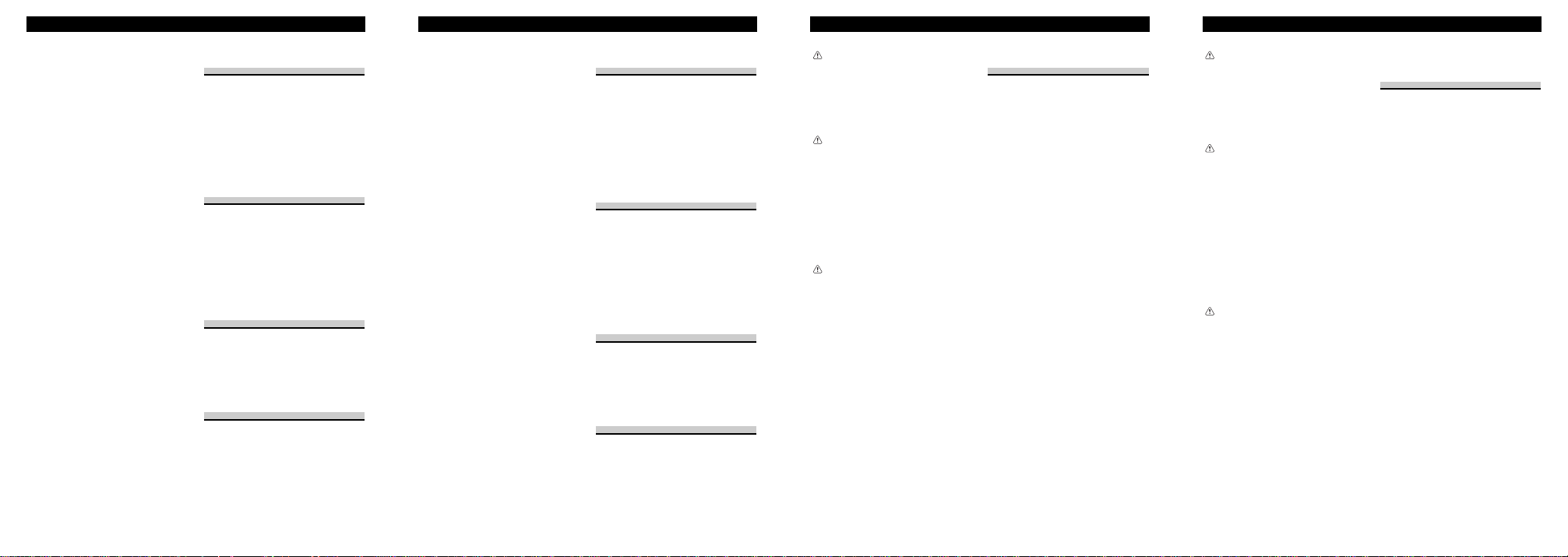
• Do not attach this unit to the outer circumference
of the steering wheel. Otherwise, it disturbs driving stability, causing a traffic accident. Always
attach this unit to the inner circumference of the
steering wheel as shown. (Fig. 8)
Note:
• Do not install this unit in such a place as may
obstruct the driver’s view.
• Since interior layout differs depending on the
type of vehicle, the ideal installation location for
the unit also differs. When installing the unit,
select a location that assures optimum transmission of signals from the unit to the car stereo.
Installing the Unit on a Left-HandDrive Car
Note:
• When the unit is installed on a right-hand-drive
car, the horizontal positions are inverted.
1. Secure inner holder to the inner
circumference of the steering wheel
with belt. (Fig. 9)
11.Inner holder
Fit the inner holder to the steering wheel so that
the arrow-marked side faces the driver as shown
by Fig. 9.
12.Belt
2. Cut the extra portion of the belt at
the center of the inner holder.
(Fig. 10)
3. Install outer holder on the inner
holder and secure with screws.
(Fig. 11)
13.Screw
Tighten the screws with the supplied hexagonal
wrench.
14.Outer holder
4. Install the remote control unit in the
holder. (Fig. 12)
15.Release section
When removing the remote control unit from the
holder, move the corrugated release section
toward the steering wheel and slide the remote
control unit toward you.
Instalación de la unidad de control remoto de dirección <ESPAÑOL>
ADVERTENCIA
• Evite instalar esta unidad en un lugar en el que la
operación de los dispositivos de seguridad tales
como las bolsas de aire sea impedida por esta
unidad. De otra manera, hay el peligro de un
accidente fatal.
• Evite instalar esta unidad en un lugar en el que la
operación del volante y la palanca de cambio sea
impedida. De otra manera, podría resultar en un
accidente de tráfico.
PRECAUCION
• La instalación de esta unidad requiere de técnicas
especializadas y de experiencia. La instalación de
esta unidad deberá ser encomendada al concesionario a quien comprù esta unidad.
• Instale esta unidad utilizando solamente las
piezas provistas con la misma. Si se utilizara
otras piezas, la unidad podría deñarse o desarmarse por si misma, lo que conllevaría a un accidente o problema.
• Instale esta unidad tal como se indica en el manual. Si falla en efectuar la instalación asÍ, podría
causar un accidente.
• No instale esta unidad cerca de las puertas donde
sea probable que el agua de la lluvia se derrame
sobre la unidad. La incursión de agua dentro de
la unidad podría causar la emisión de humos o
incendio.
ADVERTENCIA
• Fije esta unidad seguramente al volante con la
correa adjunta. Si ésta se aflojara, esto interrumpirá la estabilidad del manejo, lo que podría
resultar en un accidente de tráfico.
• No instale esta unidad fuera de la circunferencia
del volante. De otra manera, esto interrumpirá la
estabilidad del manejo, causando un accidente de
tráfico. Siempre instale esta unidad en el interior
de la circunferencia del volante, tal como se indica. (Fig. 8)
Nota:
• No instale esta unidad en un lugar en el que
obstruya la visión del conductor.
• Como la disposición interior difiere dependiendo
del tipo de vehículo, la ubicación de instalación
ideal para la unidad también difiere. Al instalar la
unidad, seleccione una ubicación que garantice la
transmisión óptima de las señales de la unidad al
estéreo del coche.
Instalación de la unidad en
el coche de manejo del lado
izquierdo
Nota:
• Cuando la unidad esté instalada en un coche de
manejo del lado derecho, las posiciones horizontales se invierten.
1. Asegure el sujetador interior en el
interior de la circunferencia del
volante con la correa. (Fig. 9)
11.Sujetador interior
Instale el sujetador interior al volante de dirección de tal manera que el lado marcado con una
flecha se dirija al conductor, tal como se muestra
en la Fig. 9.
12.Correa
2. Corte la porción extra de la correa
en el centro del sujetador interior.
(Fig 10)
3. Instale el sujetador exterior en el
sujetador interior y asegure con los
tornillos. (Fig. 11)
13.Tornillo
Apriete los tornillos con una llave hexagonal.
14.Sujetador exterior
4. Instale la unidad de control remoto
en el sujetador. (Fig. 12)
15.Sección de liberación
Cuando quite la unidad de control remoto del
sujetador, mueva la sección de liberación corrugada hacia el volante en lo posible y deslice la
unidad de control remoto hacia usted.
 Loading...