

Pioneer DEH-P6700MP Schematic
ORDER NO.
CRT3435
DEH-P6700MP/XM/EW
MULTI-CD CONTROL HIGH POWER CD/MP3/WMA PLAYER WITH RDS TUNER
DEH-P6700MP
This service manual should be used together with the following manual(s):
Model No. Order No. Mech.Module Remarks
CX-3158 CRT3394 S10.1AAC CD Mech. Module : Circuit Description, Mech. Description, Disassembly
/XM/EW
For details, refer to "Important Check Points for Good Servicing".
PIONEER CORPORATION 4-1, Meguro 1-chome, Meguro-ku, Tokyo 153-8654, Japan
PIONEER ELECTRONICS (USA) INC. P.O. Box 1760, Long Beach, CA 90801-1760, U.S.A.
PIONEER EUROPE NV Haven 1087, Keetberglaan 1, 9120 Melsele, Belgium
PIONEER ELECTRONICS ASIACENTRE PTE. LTD. 253 Alexandra Road, #04-01, Singapore 159936
PIONEER CORPORATION 2005
K-ZZA. FEB. 2005 Printed in Japan
1234
SAFETY INFORMATION
This service manual is intended for qualified service technicians; it is not meant for the casual do-it-yourselfer.
Qualified technicians have the necessary test equipment and tools, and have been trained to properly and safely
A
repair complex products such as those covered by this manual.
Improperly performed repairs can adversely affect the safety and reliability of the product and may void the warranty.
If you are not qualified to perform the repair of this product properly and safely, you should not risk trying to do so
and refer the repair to a qualified service technician.
1. Safety Precautions for those who Service this Unit.
• When checking or adjusting the emitting power of the laser diode exercise caution in order to get safe, reliable
results.
Caution:
1. During repair or tests, minimum distance of 13cm from the focus lens must be kept.
B
2. During repair or tests, do not view laser beam for 10 seconds or longer.
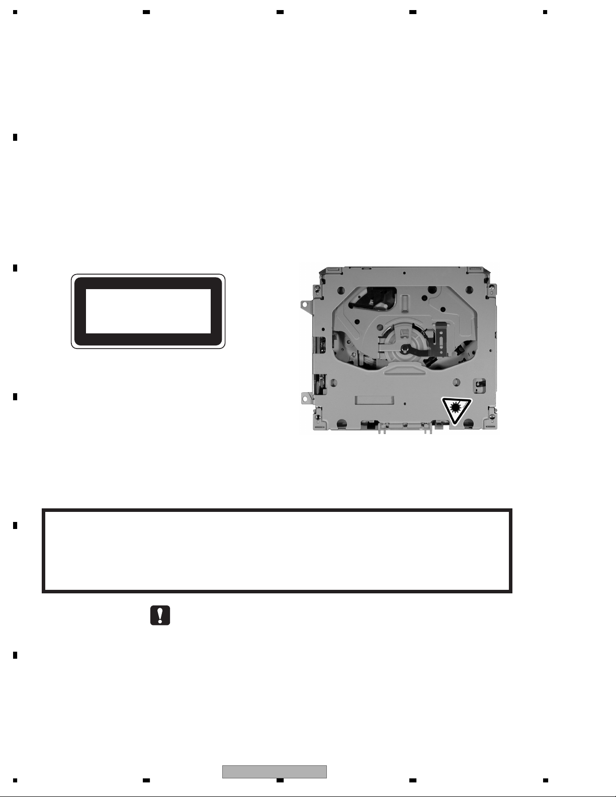
2. A “CLASS 1 LASER PRODUCT” label is affixed to the
bottom of the player.
3. The triangular label is attached to the mechanism
unit frame.
CLASS 1
LASER PRODUCT
C
D
4. Specifications of Laser Diode
Specifications of laser radiation fields to which human access is possible during service.
Wavelength = 800 nanometers
CAUTION
Danger of explosion if battery is incorrectly replaced.
Replaced only with the same or equivalent type recommended by the manufacture.
Discord used batteries according to the manufacture's instructions.
E
- Service Precaution
1. You should conform to the regulations governing the product (safety, radio and noise, and other
regulations), and should keep the safety during servicing by following the safety instructions
described in this manual.
2. Before disassembling the unit, be sure to turn off the power. Unplugging and plugging the connectors
during power-on mode may damage the ICs inside the unit.
3. To protect the pickup unit from electrostatic discharge during servicing, take an appropriate treatment
(shorting-solder) by referring to "the DISASSEMBLY".
4. After replacing the pickup unit, be sure to check the grating.
F
2
1234
DEH-P6700MP/XM/EW
5678
[Important Check Points for Good Servicing]
In this manual, procedures that must be performed during repairs are marked with the below symbol.
Please be sure to confirm and follow these procedures.
1. Product safety
Please conform to product regulations (such as safety and radiation regulations), and maintain a safe servicing environment by
following the safety instructions described in this manual.
1 Use specified parts for repair.
Use genuine parts. Be sure to use important parts for safety.
2 Do not perform modifications without proper instructions.
Please follow the specified safety methods when modification(addition/change of parts) is required due to interferences such as
radio/TV interference and foreign noise.
3 Make sure the soldering of repaired locations is properly performed.
When you solder while repairing, please be sure that there are no cold solder and other debris.
Soldering should be finished with the proper quantity. (Refer to the example)
4 Make sure the screws are tightly fastened.
Please be sure that all screws are fastened, and that there are no loose screws.
5 Make sure each connectors are correctly inserted.
Please be sure that all connectors are inserted, and that there are no imperfect insertion.
6 Make sure the wiring cables are set to their original state.
Please replace the wiring and cables to the original state after repairs.
In addition, be sure that there are no pinched wires, etc.
7 Make sure screws and soldering scraps do not remain inside the product.
Please check that neither solder debris nor screws remain inside the product.
8 There should be no semi-broken wires, scratches, melting, etc. on the coating of the power cord.
Damaged power cords may lead to fire accidents, so please be sure that there are no damages.
If you find a damaged power cord, please exchange it with a suitable one.
9 There should be no spark traces or similar marks on the power plug.
When spark traces or similar marks are found on the power supply plug, please check the connection and advise on secure
connections and suitable usage. Please exchange the power cord if necessary.
0 Safe environment should be secured during servicing.
When you perform repairs, please pay attention to static electricity, furniture, household articles, etc. in order to prevent injuries.
Please pay attention to your surroundings and repair safely.
A
B
C
D
2. Adjustments
To keep the original performance of the products, optimum adjustments and confirmation of characteristics within specification.
Adjustments should be performed in accordance with the procedures/instructions described in this manual.
3. Lubricants, Glues, and Replacement parts
Use grease and adhesives that are equal to the specified substance.
Make sure the proper amount is applied.
4. Cleaning
For parts that require cleaning, such as optical pickups, tape deck heads, lenses and mirrors used in projection monitors, proper
cleaning should be performed to restore their performances.
5. Shipping mode and Shipping screws
To protect products from damages or failures during transit, the shipping mode should be set or the shipping screws should be
installed before shipment. Please be sure to follow this method especially if it is specified in this manual.
56
DEH-P6700MP/XM/EW
E
F
7
8
3
1234
CONTENTS
SAFETY INFORMATION.....................................................................................................................................2
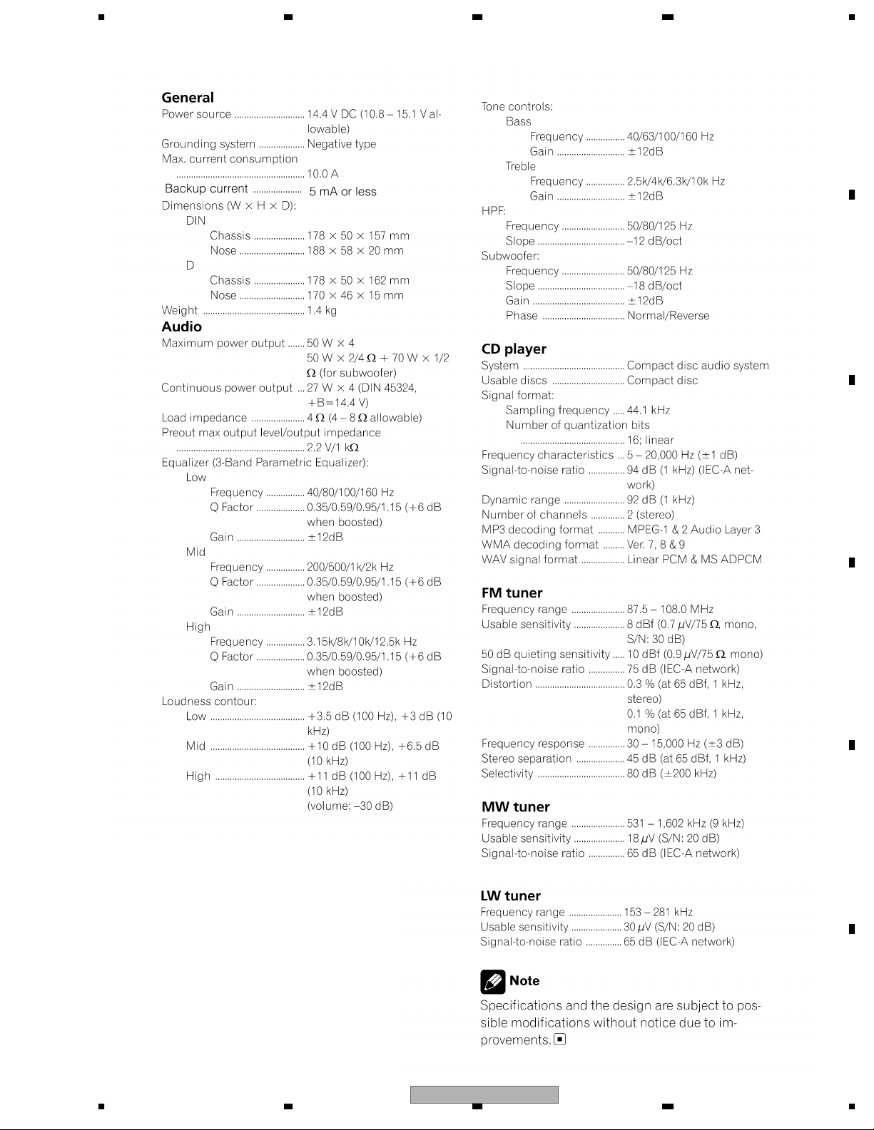
1. SPECIFICATIONS ............................................................................................................................................ 5
2. EXPLODED VIEWS AND PARTS LIST............................................................................................................6
A
B
C
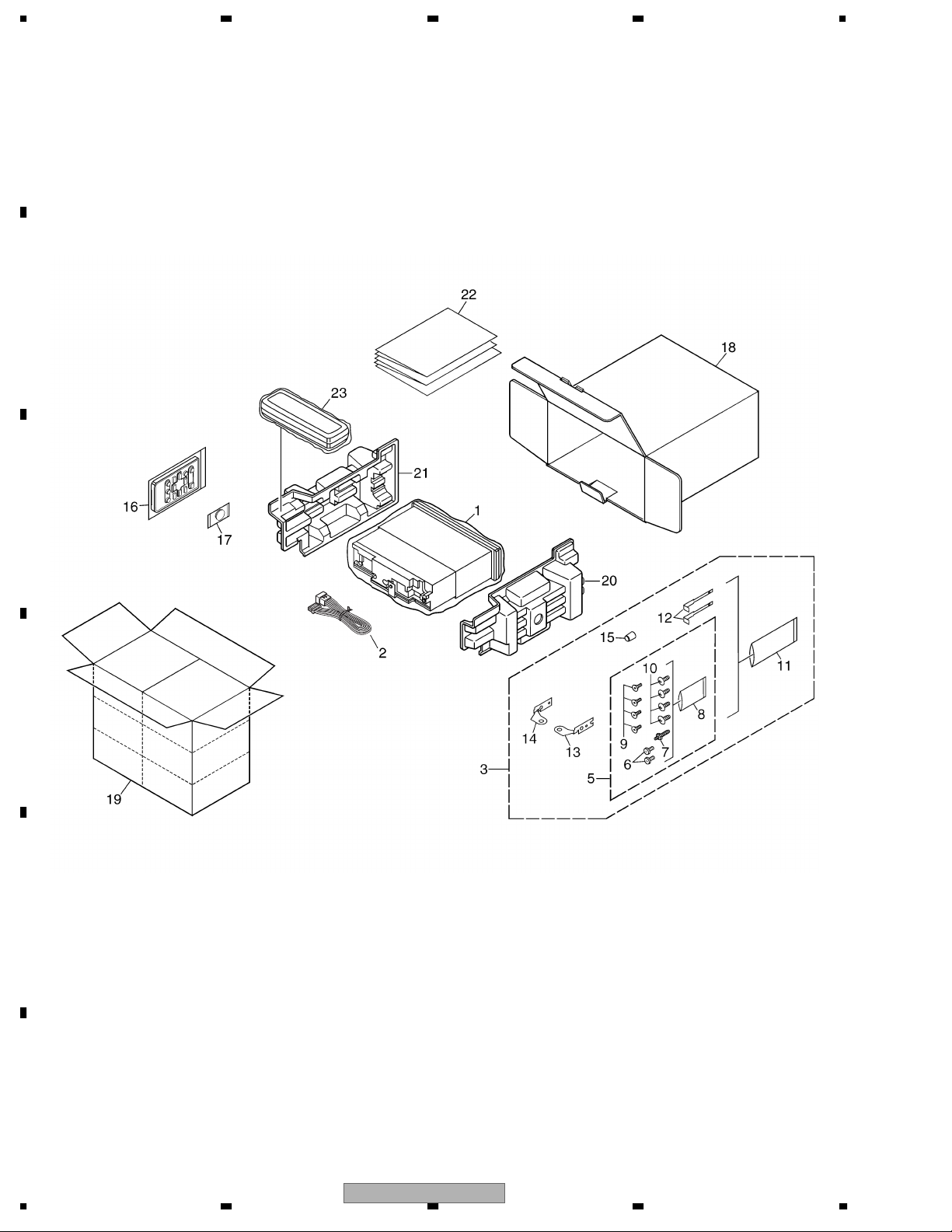
2.1 PACKING ................................................................................................................................................... 6
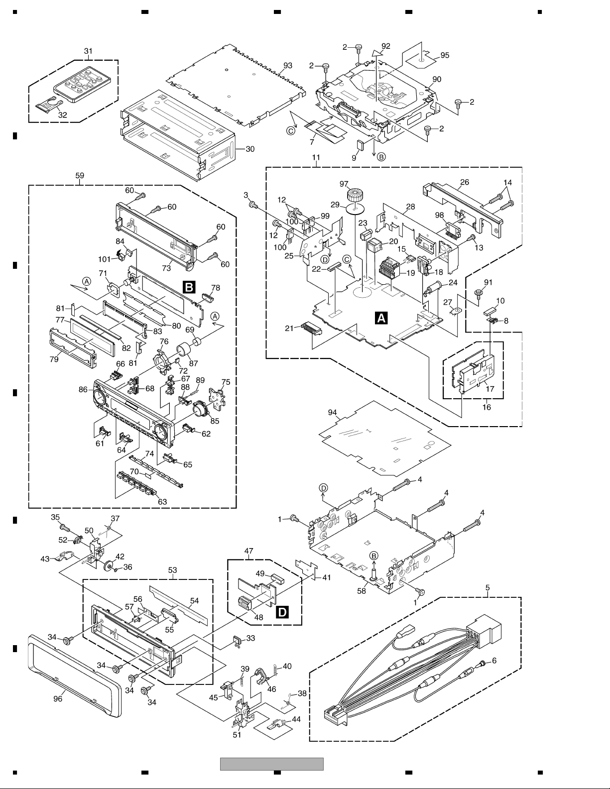
2.2 EXTERIOR................................................................................................................................................. 8
2.3 CD MECHANISM MODULE.....................................................................................................................10
3. BLOCK DIAGRAM AND SCHEMATIC DIAGRAM..........................................................................................12
3.1 BLOCK DIAGRAM................................................................................................................................... 12
3.2 OVERALL CONNECTION DIAGRAM(GUIDE PAGE).............................................................................. 14
3.3 KEYBOARD UNIT.................................................................................................................................... 20
3.4 CD MECHANISM MODULE(GUIDE PAGE)............................................................................................22
4. PCB CONNECTION DIAGRAM .....................................................................................................................32
4.1 TUNER AMP UNIT...................................................................................................................................32
4.2 KEYBOARD UNIT.................................................................................................................................... 36
4.3 CD CORE UNIT(S10.1) ........................................................................................................................... 38
4.4 PANEL UNIT ............................................................................................................................................ 40
5. ELECTRICAL PARTS LIST ............................................................................................................................41
6. ADJUSTMENT ............................................................................................................................................... 47
6.1 CD ADJUSTMENT................................................................................................................................... 47
6.2 CHECKING THE GRATING AFTER CHANGING THE PICKUP UNIT.................................................... 49
6.3 ERROR MODE ........................................................................................................................................ 51
7. GENERAL INFORMATION............................................................................................................................. 52
7.1 DIAGNOSIS............................................................................................................................................. 52
7.1.1 DISASSEMBLY..................................................................................................................................... 52
7.1.2 CONNECTOR FUNCTION DESCRIPTION.......................................................................................... 55
7.2 PARTS...................................................................................................................................................... 56
7.2.1 IC ..........................................................................................................................................................56
7.2.2 DISPLAY ............................................................................................................................................... 65
7.3 OPERATIONAL FLOW CHART............................................................................................................... 66
7.4 CLEANING............................................................................................................................................... 67
8. OPERATIONS ................................................................................................................................................ 68
D
E
F
4
1234
DEH-P6700MP/XM/EW
5678
1. SPECIFICATIONS
A
B
C
D
E
56
DEH-P6700MP/XM/EW
F
7
8
5
N
1234
2. EXPLODED VIEWS AND PARTS LIST
OTES : • Parts marked by " * " are generally unavailable because they are not in our Master Spare Parts List.
• The > mark found on some component parts indicatesthe importance of the safety factor of the part.
A
Therefore, when replacing, be sure to use parts of identical designation.
• Screw adjacent to mark on the product are used for disassembly.
• For the applying amount of lobricants or glue, follow the instructions in this manual.
(In the case of no amount instructions,apply as you think it appropriate.)
2.1 PACKING
B
"
C
D
E
F
6
1234
DEH-P6700MP/XM/EW
5678
PACKING SECTION PARTS LIST
Mark No. Description Part No.
1 Polyethylene Bag CEG-162
2 Cord Assy CDE7059
3 Accessory Assy CEA4993
4 •••••
5 Screw Assy CEA3848
6 Fixing Screw BPZ20P060FZK
7 Screw CBA1650
* 8 Polyethylene Bag CEG-127
9 Screw CRZ50P090FTC
10 Screw TRZ50P080FTC
* 11 Polyethylene Bag CEG-158
12 Handle CNC5395
13 Holder CND1249
14 Holder CND1250
15 Bush CNV3930
Owner's Manual,Installation Manual
Mark No. Description Part No.
16 Remote Control Unit CXC3173
* 17 Battery CEX1065
18 Carton CHG5476
19 Contain Box CHL5476
20 Protector XHP7003
21 Protector XHP7004
22-1 Owner's Manual CRD3959
22-2 Owner's Manual CRD3960
22-3 Owner's Manual CRD3961
22-4 Installation Manual CRD3962
* 22-5 Passport CRY1013
* 22-6 Warranty Card CRY1157
23 Case Assy CXB3520
A
B
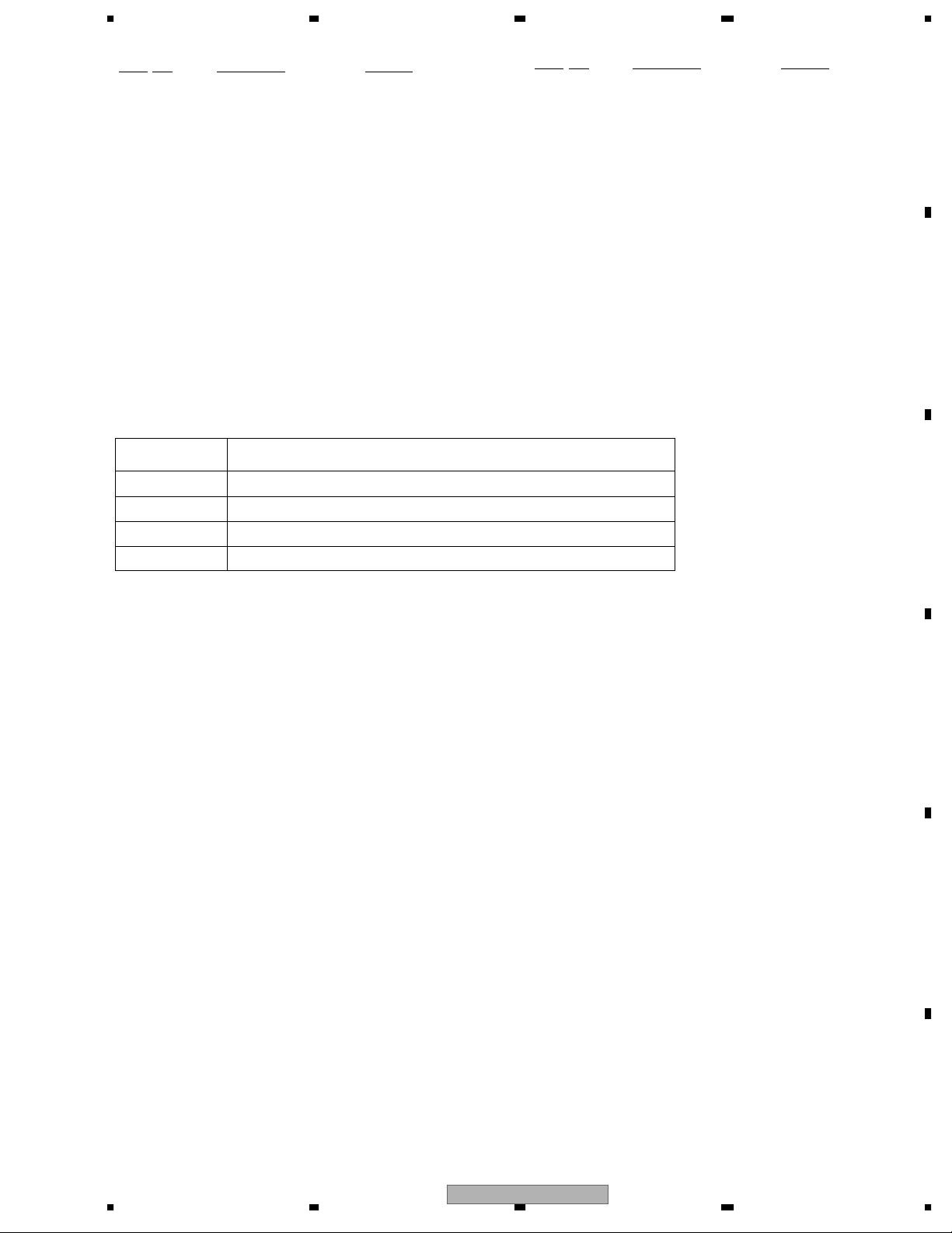
Part No. Language
CRD3959 English, Spanish
CRD3960 German, French
CRD3961 Italian, Dutch
CRD3962 English, Spanish, German, French, Italian, Dutch
C
D
56
DEH-P6700MP/XM/EW
E
F
7
8
7
1234
2.2 EXTERIOR
A
B
C
D
E
F
8
1234
DEH-P6700MP/XM/EW

5678
EXTERIOR SECTION PARTS LIST
Mark No. Description Part No.
1 Screw BMZ30P040FZK
2 Screw BSZ26P060FTC
3 Screw BSZ30P060FTC
4 Screw BSZ30P200FTC
5 Cord Assy CDE7059
6 Cap CKX-003
7 Cable CDE7189
8 Earth Plate CNC8915
9 Insulator CNM7682
10 Cushion CNM8890
11 Tuner Amp Unit CWM9790
12 Screw ASZ26P060FTC
13 Screw BPZ26P080FTC
14 Screw BSZ26P160FTC
> 15 Fuse(10A) CEK1208
16 FM/AM Tuner Unit CWE1645
17 Holder CND1054
18 Pin Jack(CN351) CKB1054
19 Plug(CN981) CKM1376
20 Connector(CN101) CKS3408
21 Plug(CN831) CKS3537
22 Connector(CN721) CKS3837
23 Connector(CN671) CKS4124
24 Antenna Jack(CN401) CKX1056
25 Holder CND1352
26 Heat Sink CNR1668
27 Terminal(CN402) VNF1084
28 Holder XNC7003
29 Insulator XNM7031
30 Holder Unit CXB6681
31 Remote Control Unit CXC3173
32 Cover CNS7068
33 Button(EJECT) CAC7752
34 Screw(M2x4.5) CBA1647
35 Screw(M2x4) CBA1649
36 Washer CBF1038
37 Spring CBH2650
38 Spring CBH2651
39 Spring CBH2652
40 Spring CBH2653
41 Holder CND1254
42 Gear CNV5997
43 Arm CNV7400
44 Arm CNV7401
45 Arm CNV7402
46 Arm CNV7403
47 Panel Unit CWM9781
48 Connector(CN1951) CKS4806
49 Connector(CN1950) CKS5192
50 Holder Unit CXB9501
51 Holder Unit CXB9502
No. Description Part No.
Mark
52 Damper Unit CXB9503
53 Sub Panel Unit XXA7361
54 Cover CNM6854
55 Lighting Conductor CNV6487
56 Spring CBL1512
57 Pin CNV6486
58 Chassis Unit CXC4063
59 Detach Grille Assy CXC4175
60 Screw BPZ20P100FZK
61 Button(DISPLAY) CAC9036
62 Button(SW) CAC9037
63 Button(1-6) CAC9038
64 Button(SOURCE) CAC9039
65 Button(BAND) CAC9040
66 Button(TA) CAC9041
67 Button(FUNCTION, AUDIO) CAC9042
68 Button(EQ, ILLUMINATION) CAC9043
69 Spring CBL1470
70 Sheet CNM9482
71 Sheet CNM9560
72 Sheet CNM9561
73 Cover CNS8149
74 Lighting Conductor CNV8361
75 Lighting Conductor CNV8362
76 Lighting Conductor CNV8363
77 LCD(LCD1) CAW1865
78 Connector(CN1) CKS5207
79 Holder CND2510
80 Sheet CNM9366
81 Sheet CNM9367
82 Connector CNV8275
83 Lighting Conductor CNV8360
84 Cushion XNM7049
85
86 Sub Grille Assy CXC4243
87 Knob(VOLUME) XAA7021
88 Button(OPEN) XAC7065
89 Spring XBH7001
90
91 Screw ISS26P055FTC
92 Label VRW-329
93 Case XNB7002
94 Insulator XNM7100
95 Insulator XNM7106
96 Panel XNS7089
97 Choke Coil(L981) CTH1291
98 IC(IC301) PAL007A
99 IC(IC911) NJM2388F84
100 Transistor(Q751, 901) 2SD2396
101 IC(IC3) TSOP4840SB1
Sub Button Assy(UP, DOWN, LEFT, RIGHT)
CD Mechanism Module(S10.1AACA)
CXC4242
CXK5668
A
B
C
D
E
F
56
DEH-P6700MP/XM/EW
7
8
9
1234
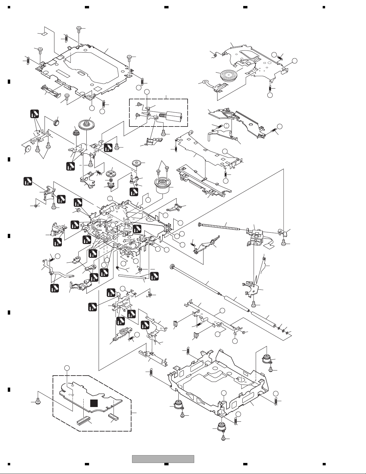
2.3 CD MECHANISM MODULE
42
A
5
13
13
5
81
34
5
15
22
E
F
93
13
A
44
B
5
B
1
54
52
53
13
C
D
86
86
82
83
4
37
71
4
29
51
1
73
50
72
10
1
I
76
B
55
5
36
4
1
18
2
64
47
C
24
2
1
7
61
2
M
1
23
87
75
E
63
57
62
58
1
G
L
1
N
R
1
1
2
1
40
56
D
O
16
P
1
33
1
P
19
J
12
3
20
39
1
69
30
2
21
M
D
79
2
1GEM1024
2GEM1045
3GEM1035
E
92
26
G
68
28
I
H
28
45
J
38
23
K
59
49
F
Q
A
27
H
77
90
48
8
67
17
78
25
70
60
80
N
L
K
43
46
6
60
11
89
10
14
74
R
31
41
85
C
91
F
C
65
1
2
3
85
66
35
O
31
Q
14
85
10
1234
DEH-P6700MP/XM/EW

5678
CD MECHANISM MODULE SECTION PARTS LIST
Mark No. Description Part No.
1 CD Core Unit(S10.1) CWX3096
2 Connector(CN101) CKS4182
3 Connector(CN901) CKS4017
4 Screw BMZ20P035FTC
5 Screw BSZ20P040FTC
6 Screw(M2x4) CBA1362
7 Screw(M2x3) CBA1824
8 Screw(M2x3) CBA1825
9 •••••
10 Washer CBF1038
11 Washer CBF1060
12 Spring CBH2390
13 Spring CBH2606
14 Spring CBH2607
15 Spring CBH2608
16 Spring CBH2609
17 Spring CBH2610
18 Spring CBH2735
19 Spring CBH2612
20 Spring CBH2613
21 Spring CBH2614
22 Spring CBH2615
23 Spring CBH2616
24 Spring CBH2617
25 Spring CBH2620
26 Spring CBH2621
27 Spring CBH2641
28 Spring CBH2642
29 Spring CBH2643
30 Spring CBH2659
31 Spring CBH2688
32 •••••
33 Shaft CLA4441
34 Frame CNC9962
35 Frame CNC9963
36 Bracket CND2712
37 Bracket CND1895
38 Arm CNC9968
39 Arm CND1909
40 Lever CND2032
41 Lever CNC9984
42 Sheet CNM8134
43 Collar CNV7798
44 Guide CNV7799
45 Arm CNV8403
Mark No. Description Part No.
50 Gear CNV8379
51 Gear CNV8380
52 Gear CNV8381
53 Gear CNV8382
54 Gear CNV8383
55 Gear CNV8384
56 Rack CNV8385
57 Arm CNV8386
58 Arm CNV8387
59 Guide CNV8388
60 Roller CNV7218
61 Gear CNV8389
62 Arm CNV8391
63 Arm CNV8390
64 Arm CNV8392
65 Damper CNV7313
66 Damper CNV7314
67 Arm CNV8394
68 Arm CNV8395
69 Guide CNV8396
70 Guide CNV8397
71 Holder CNV8398
72 Arm CNV8402
73 Gear CNV8400
74 Damper CNV7618
75 Motor Unit(M1) CXC4440
76 Chassis Unit CXC2318
77 Screw Unit CXB8729
78 Gear Unit CXC2397
79 Arm Unit CXC2316
80 Arm CND1896
81 Arm CND1894
82 Motor Unit(M2) CXB8933
83 Bracket CNC9985
84 •••••
85 Screw(M2x5) EBA1028
86 Screw JFZ20P020FTC
87 Screw JGZ17P022FTC
88 •••••
89 Washer YE20FTC
90 Pickup Unit(P10)(Service) CXX1641
91 Screw IMS26P030FTC
92 Spring CBL1635
93 Clamper CNV8372
A
B
C
D
E
46 Rack CNV8374
47 Holder CNV8376
48 Holder CNV8377
49 Arm CNV8378
56
DEH-P6700MP/XM/EW
F
7
8
11
2
4
4
3
E
O
EVCK EVDT EVST
G
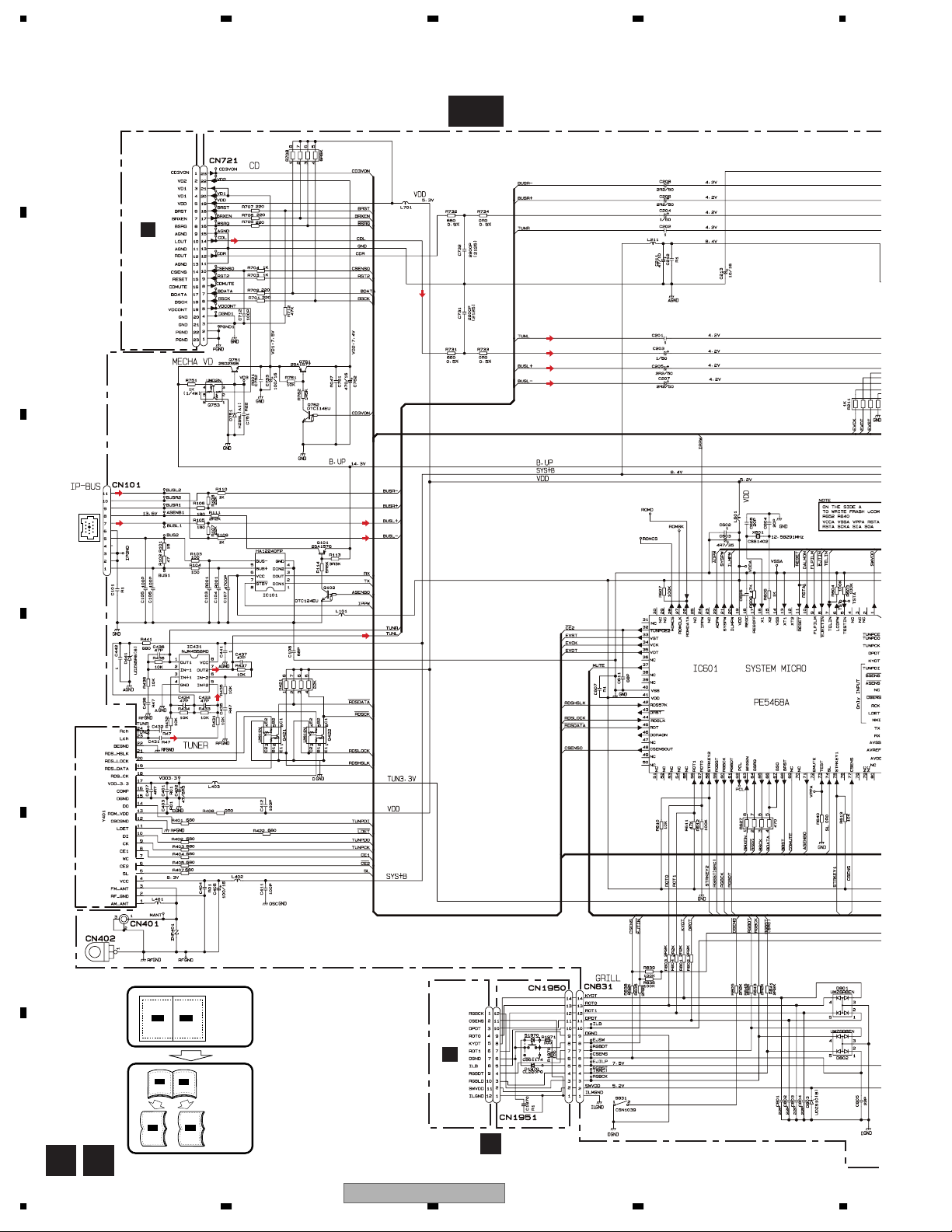
1234
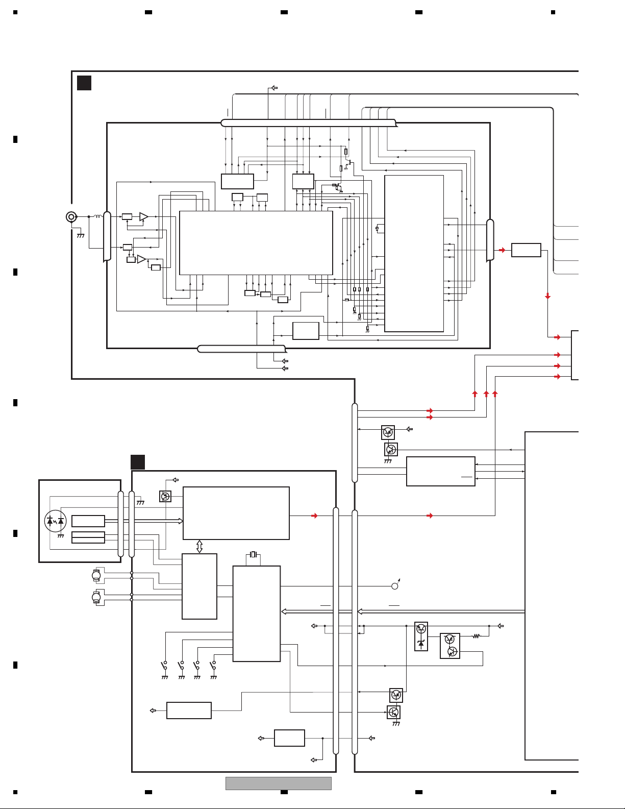
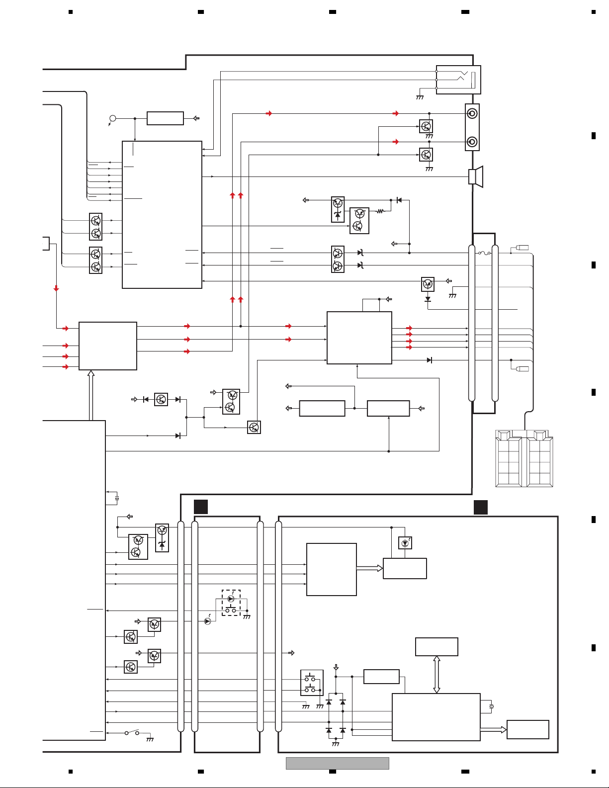
3. BLOCK DIAGRAM AND SCHEMATIC DIAGRAM
3.1 BLOCK DIAGRAM
A
TUNER AMP UNIT
A
VDD
B
C
D
E
F
ANTENNA
CN401
2,3
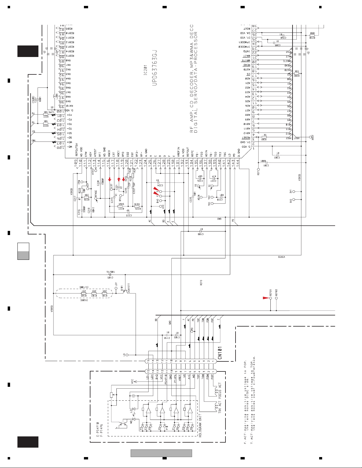
PICKUP UNIT
(P10)(SERVICE)
LASER
DIODE
TRACKING ACT.
MONITOR
DIODE
SPINDLE
MOTOR
M2
LOADING/CARRIAGE
MOTOR
1
HOLOGRAM
UNIT
FOCUS ACT.
M1
FM/AM TUNER UNIT
AM ANT
1
ATT
FM ANT
3
ATT
FMRF
ANT adj
C
CN101
LD-
15
15
MD
5
5
FOP
FOP
1
1
TOP
TOP
4
4
LD+
14
14
M
M
V3R3D
FMRF
RF adj
RFGND
212 1522 16 4 17
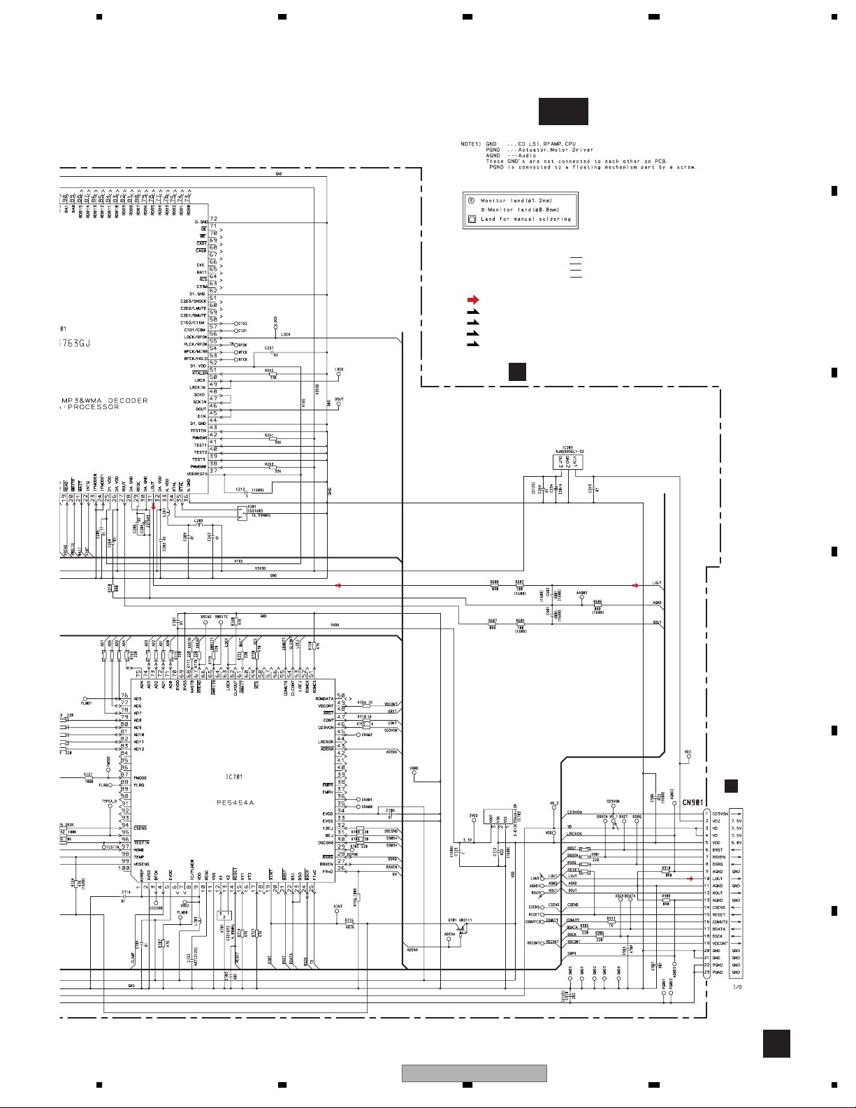
CD CORE UNIT(S10.1)
V3R3D
142
Q101
AC,BD
E,F
LD
143
PD
RF AMP, CD DECODER,
MP3 AND WMA DECODER,
DIGITAL SERVO/DATA PROCESSOR
FD,TD
12
FOP
13
TOP
DRIVER
16
SOP
15
SOM
18
LCOP
17
LCOM
IC301
BA5835FP
S904
S905
8EJ
DSCSNS
3
IC203
NJM2885DL1-33
S903
12EJ
3.3V REGULATOR
SD,MD
CD
LOEJ
CONT
S901
HOME
1
CE2
76 13 5 1098 11 14 18192021
WC
CE2
IC3 EEPROM
5.0V
OSC
LPF
IC1
3.3V
MIXER, IF AMP
T51
CF52
OSCGND
DGND
AUDIOGNDNCVCC
IC201
UPD63763GJ
X701
1312
X1
X2
MICRO
COMPUTER
53
22
9
47
32
31
30
97
VD2
LOEJ
CONT
12EJ
8EJ
DSCSNS
HOME
IC701
PE5454A
reset
VDCONT
CD3VON
ROM_VDD
VDD_3.3
CF51
LOUT
14
49
46
SL
3.3V
TUN3.3V
SYS+B
TUNPDO
TUNPCK
DI
CK
CE1
IC5
←
5V 3.3V
IC4
←
3.3V 2.5V
CN901
31
RESET
BRST,BRXEN,BSRQ
BDATA,BSCK
VD
VDCONT
CD3VON
2.5V
LOUT
LDET
IP-BUS
VD
VD2
LDET
TUNPDI
DO
11
7
8
5
1
14
10
15
9
3
21
4
20
19
5
22
2
1
23
RDS_CK
CN101
BUSLBUSL+
CN721
LOUT
RESET RST2
BRST,BRXEN,BSRQ,BDATA,BSCK
VD1
VDCONT
VD2
CD3VON
3V REGULATOR
3VDD
3
IC703
2
5
19
VDD
S-812C33AUA-C2N
VDD
RDS_DATA
RDS_HSLK
RDS_LOCK
Q101
VDD
DET, FM MPX,
RDS DECODER
Q102
5
6
A
Q761
Q762
IC2
2.5V
BUSBUS+
B.UP
ASENBO
Q751
DIN1
IC101
HA12240FP
DOUT
STBY
CDL
Q753
34
5
2
Rch
24
Lch
23
1
2
8
IC431
NJM4558MD
71
86
85
24
ASENBO
TX
RX
IPPW
RDS_DATA
RDS_HSLK
75
RDS_CK
RDS_LOCK
EL
S
TUN L
41
IN
44
IN
43
IN
42
IN
CDL
SYSTEM CONTRO
IC601(2/2)
PE5468A
R
B.UP
12
1234
DEH-P6700MP/XM/EW
5678
RDS_DATA
RDS_HSLK
7
D
RDS_CK
RDS_LOCK
ELECTRONIC VOLUME/
SOURCE SELECTOR
TUN L
41
IN2L
44
IN4-L
43
CDL
NBO
W
IN4+L
42
IN3L
YSTEM CONTROLLER
IC601(2/2)
PE5468A
RGBST/SRC
A
TUNPDO
LDET
TUNPDI
SL
TUNPCK
CE1
CE2
Q421
Q422
IC251
PML009A
EVCK, EVDT, EVST
37
MUTE
21
SYSPW
16
X1
15
X2
20
ILMPW
59
60
RGBCK
61
RGBDT
8
EJECTIN
9
FLPILM
1
SWVDD
56
ROT1
57
ROT0
77
CSENS
96
DPDT
95
KYDT
90
DSENS
RST2
98
TUNPDO
88
LDET
94
TUNPDI
74
SL
97
TUNPCK
99
TUNPCE
32
TUNPCE2
45
RDT
42
RDS57K
89
RCK
44
RDSLK
Frontout_L
Rearout_L
Preout_L
B.UP
X601
12.58291MHz
B.UP
VDD
Q852
Q862
S831
IC651
BD4834G
11
RESET
SYSTEM CONTROLLER
IC601(1/2)
PE5468A
10
11
12
MUTE
Q391
B.UP
CN831
Q881
Q882
5
RGBST(SRC)
RGBCK
RGBDT
Q861
Q851
SWVDD
CSENS
RESET
12
DSENS
EJSW
EJILP
ROT1
ROT0
DPDT
KYDT
2
3
1
CN671
WIRED REMOTE CONTROL
A
CN351
8
RL
B.UP
23
21
3
5
25
SYSPW
Q1-Q14
LED DRIVE
1
RFM
DPDT
KYDT
VLCD
VDD
Q352
Q351
TEL IN
Q951
1213
B.UP
SYSPW
(RGB)
KEY MATRIX
17
KEY DATA
LCD DRIVER/
KEY CONTROLLER
IC1
PD6340A
FL
SP601
CN981
VDD
VDD
58
STRKEY2
75
STRKEY1
100
PEE
VDD 5V REG
VDD
10
DALMON
93
BSENS
92
ASENS
7
TELIN
MUTE
Q371
B.UP
PANEL UNIT
D
CN1950
ILB
10
10
4
4
3
3
7
7
8
8
5
5
2
2
12
12
13
13
6
6
11
11
14
14
CN1951
S1970
EJECT
TUN3.3V
Q301
ILB BL+B
5
RGBLD
3
RGBCK
12
RGBDT
4
SWVDD
2
ROT1
7
ROT0
9
CSENS
11
DPDT
10
KYDT
8
BSENS
ASENS
SYS+B
CN1
8
12
DAST
10
13
DACLK
1
14
DADT
9
11
SWVDD
VOLUME
1
ROT1
6
2
ROT0
4
2
DPDT
3
KYDT
5
Q901
BACKUP SENSE
Q931
ACC SENSE
AMP
14
RLIN
12
FLIN
22
MUTE
TUN 3V REG.
IC921
NJM2391DL1-33
IC2
MB88347PFV-G-BND
LD(B)
CLK(R)
DI(G)
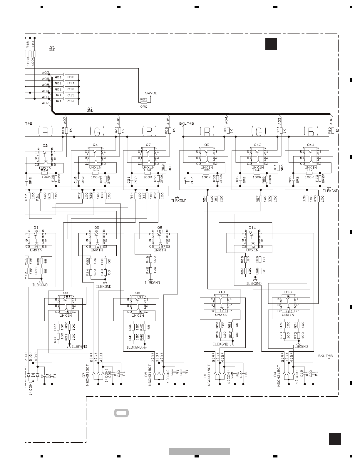
RGB CONTROLLER
SWVDD
S1
3
Q902
VCC3/4 VCC1/2
IC301
PAL007A
STBY
4
A02-A07
3
B.UP
ACC
6
20
FLFL+
RL-
RL+
B.REMOTE
SYS 8V REG.
IC911
NJM2388F84
REM.CON.
IC3
TSOP4840SB1
4
18
20
10
56
SUBWOOFER OUTPUT
NON FADING OUTPUT
4
FRONT OUTPUT
FUSE
16
16
10A
14
14
15
15
9
9
7
7
5
5
8
8
6
6
11
11
KEYBOARD UNIT
B
22
XO
X1
4.97MHz
23
XI
BACK
GND
B
BACK UP
ACC
GND
TEL
FLFL+
RL-
RL+
B.REM
RR
RR
+
FR
REM
ACC
FR
+
-
B.
FL
FL
+
-
RL
RL
+
-
UP
C
D
E
F
LCD1
56
DEH-P6700MP/XM/EW
7
8
13
)
S
1234
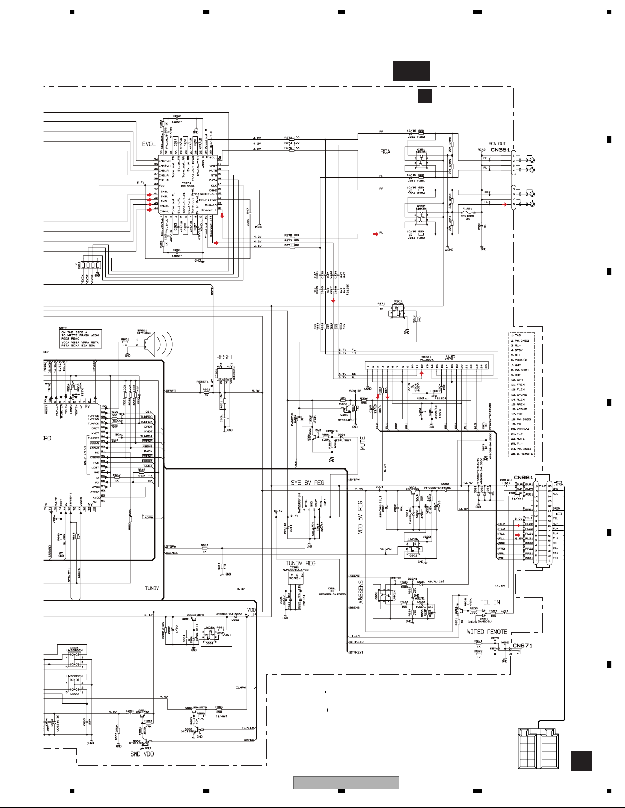
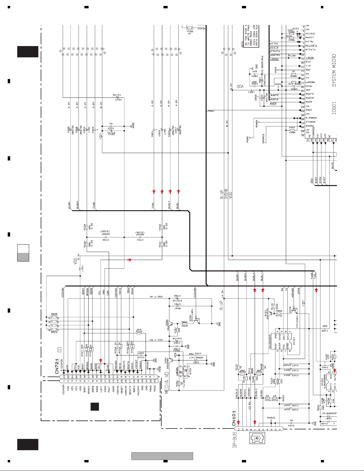
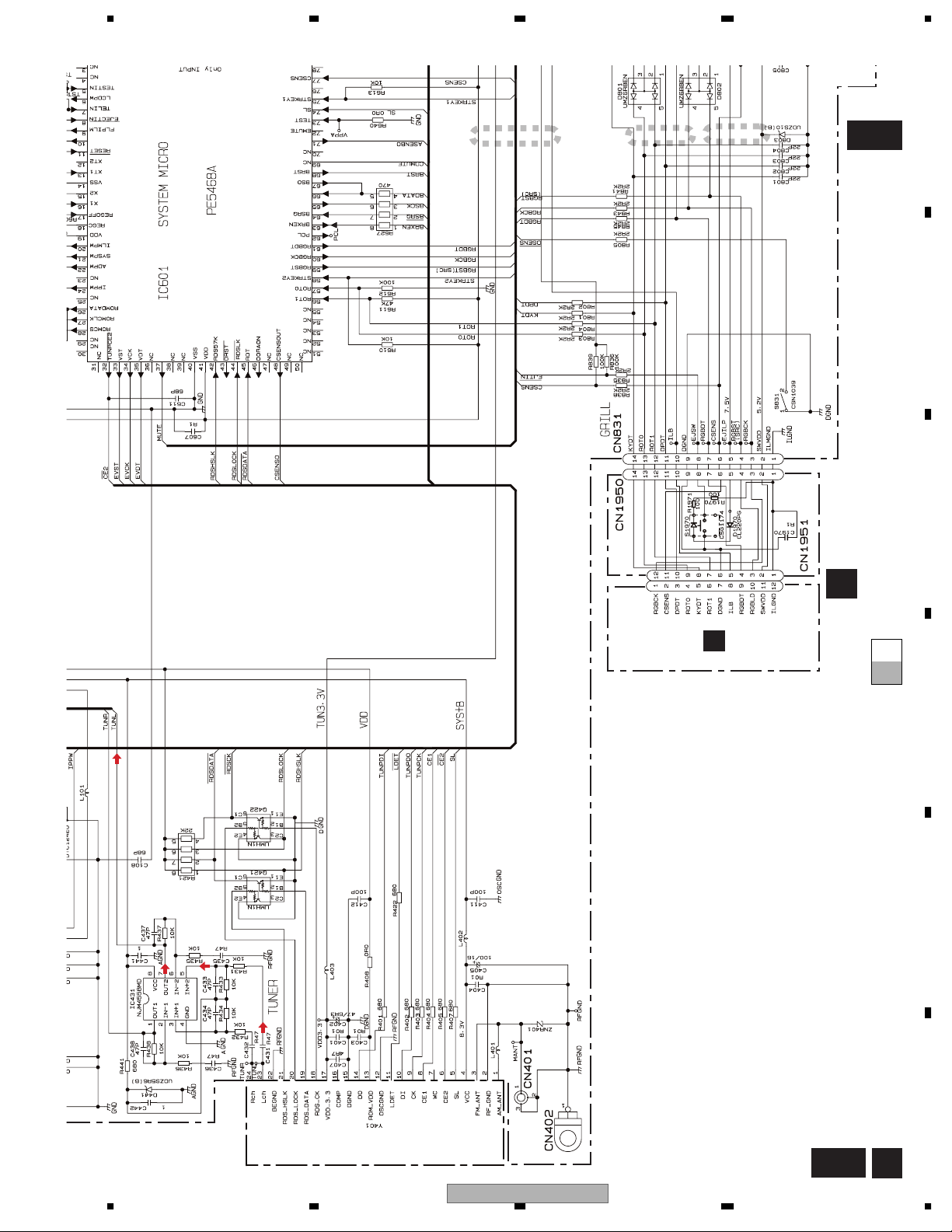
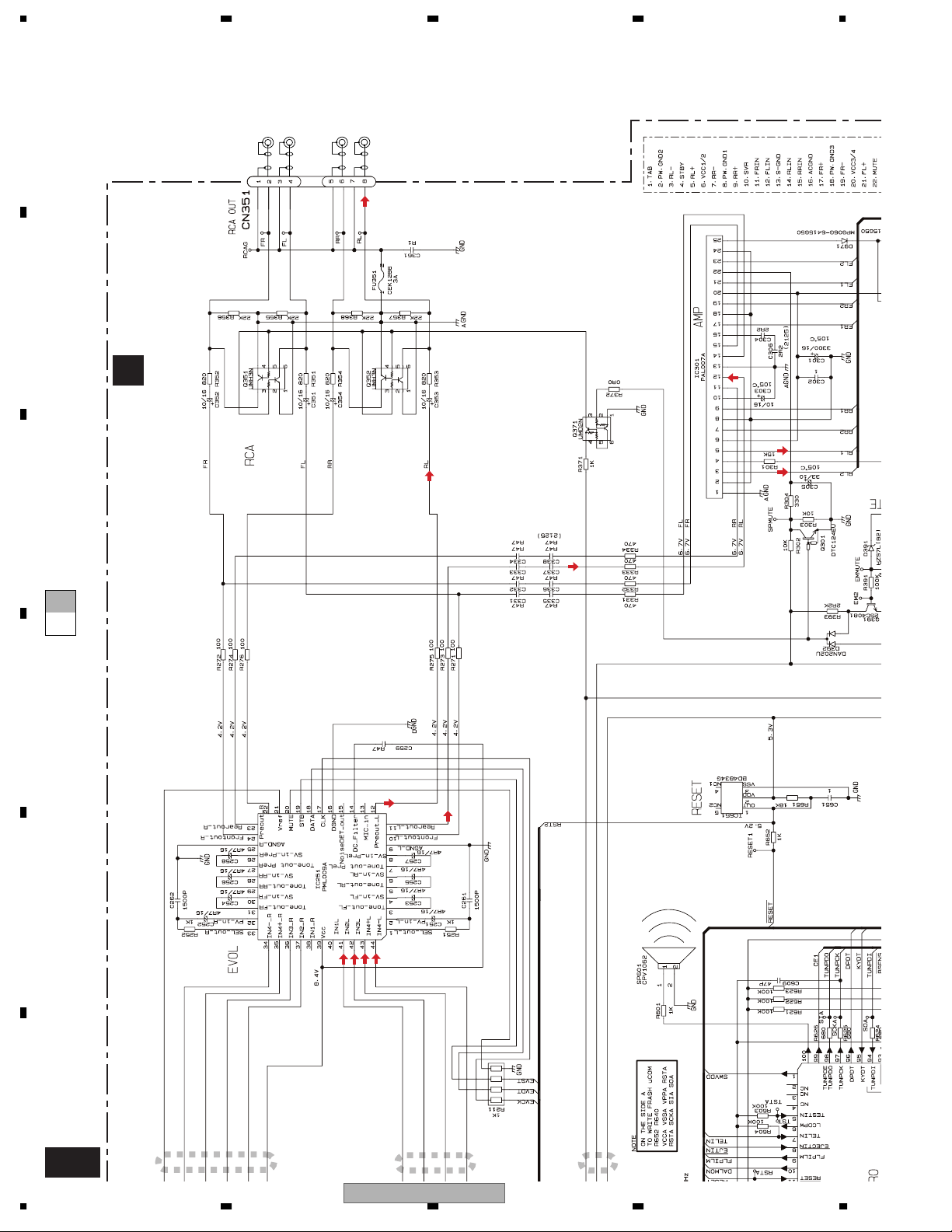
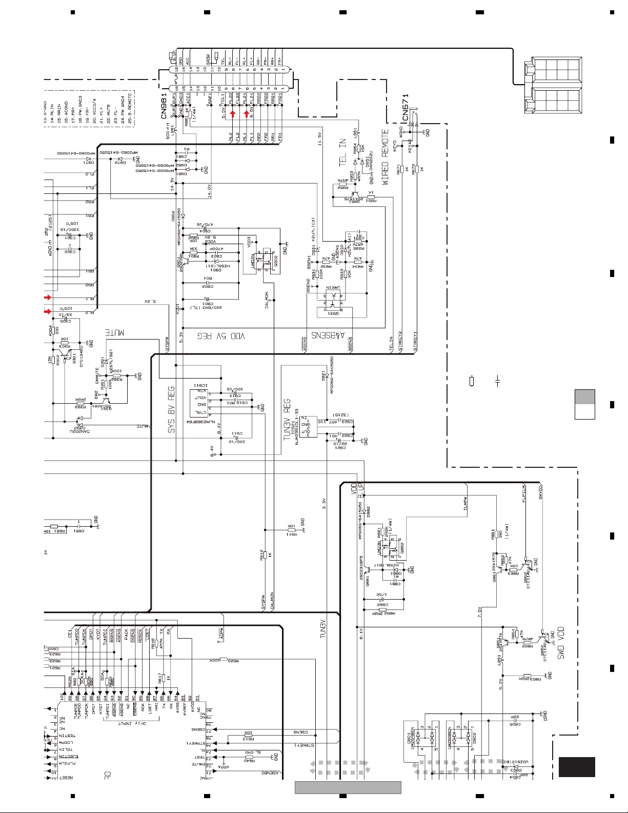
3.2 OVERALL CONNECTION DIAGRAM(GUIDE PAGE)
Note: When ordering service parts, be sure to refer to " EXPLODED VIEWS AND PARTS LIST" or
"ELECTRICAL PARTS LIST".
A
C
CN901
A-a
B
CD-DA, MP3 : 0.2dB
FM(30%
AM(30%
CD-DA, MP
IP-BU
C
1432
811109
576
IP-BUS : 2.2dB
swvdd
dalmon
mute
BEEP
D
E
F
A D
14
TSCK/BSCK
FM/AM TUNER UNIT
FM(30%) : -26dB
AM(30%) : -26dB
CSA30-201N
A-a A-b
Large size
SCH diagram
TSI/BSI
EJECT
CN1
ASENSBO
NC
NC
B
A-a
A-b
Guide page
A-b
Detailed page
PANEL UNIT
D
A-a
DEH-P6700MP/XM/EW
1234
DSENS
5678
FM(30%) : -27dB
AM(30%) : -27dB
IP-BUS : 2.2dB
CD-DA, MP3 : 0.2dB
FM(30%) : -3.9dB
AM(30%) : -1.9dB
IP-BUS : 10.3dB
CD-DA, MP3 : 10.3dB
A-b
TUNER AMP UNIT
A
A
FRONT
R CH
FRONT
L CH
REAR
R CH
REAR
L CH
>
FM(30%) : -4.66dB
AM(30%) : -2.66dB
IP-BUS : 9.54dB
CD-DA, MP3 : 9.54dB
B
C
dalmon
ASENSBO
swvdd
BEEP
D
>
CEK1208
10A
NC
NC
FM(30%) : 22.1dB
AM(30%) : 24.1dB
IP-BUS : 36.3dB
CD-DA, MP3 : 36.3dB
E
NOTE :
Symbol indicates a resistor.
No differentiation is made between chip resistors and
discrete resistors.
Symbol indicates a capacitor.
No differentiation is made between chip capacitors and
discrete capacitors.
The > mark found on some component parts indicates
the importance of the safety factor of the part.
Therefore, when replacing, be sure to use parts of
identical designation.
DEH-P6700MP/XM/EW
56
7
Decimal points for resistor
and capacitor fixed values
are expressed as :
←
2.2 2R2
←
0.022 R022
BACK
UP
B.
REM
ACC
GND
RR
RR
+
FR
FR
+
FL
FL
+
RL
RL
+
-
A
8
F
15
A
M
M
B
A-b
1234
I
A
F
CD-D
1
2
3
dalmon
mute
C
A-b
A-a
A-a
D
E
F
A-a
16
C
CD-DA, MP3 : 0.2dB
CN901
1432
576
811109
DEH-P6700MP/XM/EW
1234
IP-BUS : 2.2dB
NC
5678
NC
dalmon
mute
ASENSBO
TSI/BSI
TSCK/BSCK
4
5
EJECT
6
DSENS
A-b
A
B
C
PANEL UNIT
CSA30-201N
CN1
B
D
A-b
A-a
A-a
D
E
AM(30%) : -26dB
FM/AM TUNER UNIT
FM(30%) : -26dB
DEH-P6700MP/XM/EW
56
F
A-a
7
8
D
17
1234
A
REAR
FRONT
R CH
FRONT
L CH
R CH
REAR
L CH
IP-BUS : 9.54dB
FM(30%) : -4.66dB
AM(30%) : -2.66dB
CD-DA, MP3 : 9.54dB
>
B
TUNER AMP UNIT
A
C
A-b
A-a
IP-BUS : 10.3dB
FM(30%) : -3.9dB
D
AM(30%) : -1.9dB
CD-DA, MP3 : 10.3dB
E
F
A-b
18
BEEP
swvdd
IP-BUS : 2.2dB
AM(30%) : -27dB
FM(30%) : -27dB
CD-DA, MP3 : 0.2dB
1
2
3
dalmon
DEH-P6700MP/XM/EW
1234
5678
+
+
+
+
RL
FL
FR
>
10A
CEK1208
IP-BUS : 36.3dB
FM(30%) : 22.1dB
AM(30%) : 24.1dB
CD-DA, MP3 : 36.3dB
RR
-
RR
←
←
Decimal points for resistor
and capacitor fixed values
are expressed as :
2.2 2R2
0.022 R022
FR
BACK
-
-
-
RL
FL
B.
REM
ACC
UP
GND
A
B
C
The > mark found on some component parts indicates
the importance of the safety factor of the part.
Therefore, when replacing, be sure to use parts of
Symbol indicates a resistor.
No differentiation is made between chip resistors and
discrete resistors.
Symbol indicates a capacitor.
No differentiation is made between chip capacitors and
discrete capacitors.
identical designation.
NOTE :
A-b
A-a
D
E
BEEP
swvdd
dalmon
NC
NC
ASENSBO
4
DEH-P6700MP/XM/EW
56
F
5
7
6
8
A-b
19
1234
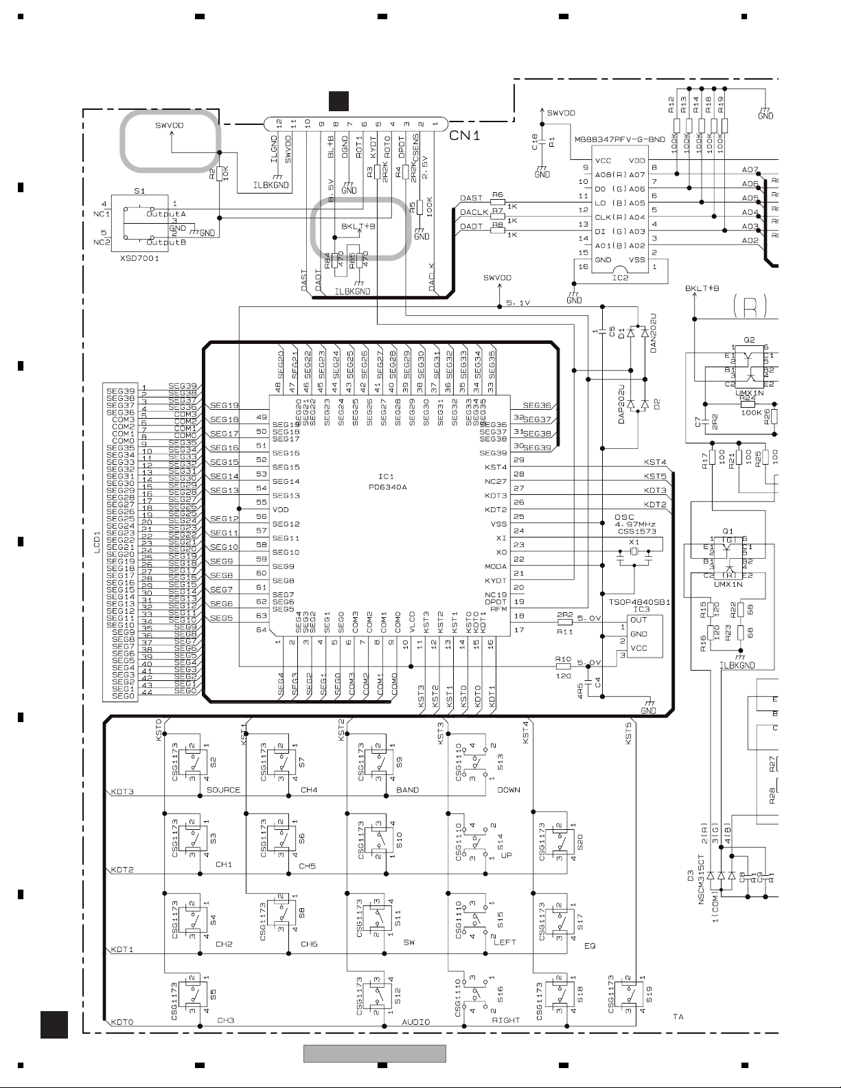
3.3 KEYBOARD UNIT
A
VOLUME
B
C
D
CN1951
RGB CONTROLLER
LCD DRIVER/
KEY CONTROLLER
CAW1865
D
REM. CON.
E
FUNCTION
ILLUMINATION
F
DISPLAY
B
20
1234
DEH-P6700MP/XM/EW
5678
KEYBOARD UNIT
B
A
B
C
: The power supply is shown with the marked box.
D
E
F
56
DEH-P6700MP/XM/EW
B B
7
8
21
1234
Y
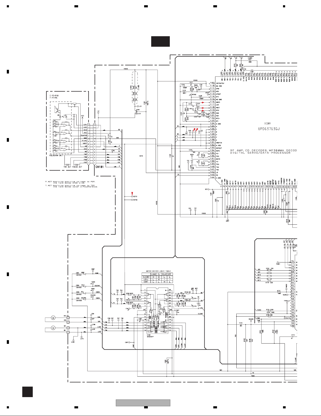
3.4 CD MECHANISM MODULE(GUIDE PAGE)
A
PICKUP UNIT(P10)(SERVICE)
B
C-a
F
T
C
S
%
F
T
F
T
T
F
F
T
F
F
T
T
#
@
C
D
3
2
1
E
M1 CXC4440
SPINDLE MOTOR
M2 CXB8933
LOADING
/CARRIAGE
MOTOR
S
S
C
C
T
9
F
0
F
F
T
T
CD DRIVER
$
S
7
C
8
4
5
S
C
S
C
T
F
C
22
1234
DEH-P6700MP/XM/EW
5678
A
C-b
SWITCHES:
CD CORE UNIT(S10.1)
ras
!
S901:HOME SWITCH..........ON-OFF
S903:DSCSNS SWITCH......ON-OFF
S904:12EJ SWITCH.............ON-OFF
S905:8EJ SWITCH...............ON-OFF
The underlined indicates the switch position.
SIGNAL LINE
F
FOCUS SERVO LINE
T
TRACKING SERVO LINE
C
CARRIAGE SERVO LINE
S
SPINDLE SERVO LINE
CD CORE UNIT(S10.1)
C
B
TYPE_A/D
MICRO COMPUTER
SRAMLEVEL2
SRAMLEVEL1
SRAMLEVEL0
3V REGULATOR
3.3V REGULATOR
C
D
A
CN721
6
E
^
&
DEH-P6700MP/XM/EW
56
F
C
7
8
23
A
C-b
1234
1
2
B
C
C-b
A-a
C-a
F
T
C
S
#
@
%
T
T
F
F
D
E
F
C-a
24
T
T
F
F
T
TFF
PICKUP UNIT(P10)(SERVICE)
DEH-P6700MP/XM/EW
1234
 Loading...