

PIONEER DEH-P3600, DEH- P3630M Service Manual
PIONEER CORPORATION 4-1, Meguro 1-chome, Meguro-ku, Tokyo 153-8654, Japan
PIONEER ELECTRONICS (USA) INC. P.O. Box 1760, Long Beach, CA 90801-1760, U.S.A.
PIONEER EUROPE NV Haven 1087, Keetberglaan 1, 9120 Melsele, Belgium
PIONEER ELECTRONICS ASIACENTRE PTE. LTD. 253 Alexandra Road, #04-01, Singapore 159936
PIONEER CORPORATION 2003
ORDER NO.
CRT3170
DEH-P3600MP/XM/EW
MULTI-CD CONTROL HIGH POWER CD/MP3/WMA PLAYER WITH RDS TUNER
DEH-P3600MP
DEH-P3600MPB
DEH-P3630MP
This service manual should be used together with the following manual(s):
Model No. Order No. Mech.Module Remarks
CX-3098 CRT3179 S10WMAcode2 CD Mech. Module:Circuit Description, Mech. Description, Disassembly
/XM/EW
/XM/EW
/XM/EW
For details, refer to "Important symbols for good services".
K-ZZW. NOV. 2003 printed in Japan
1234
SAFETY INFORMATION
This service manual is intended for qualified service technicians; it is not meant for the casual do-it-yourselfer.
Qualified technicians have the necessary test equipment and tools, and have been trained to properly and safely
A
repair complex products such as those covered by this manual.
Improperly performed repairs can adversely affect the safety and reliability of the product and may void the warranty.
If you are not qualified to perform the repair of this product properly and safely, you should not risk trying to do so
and refer the repair to a qualified service technician.
1. Safety Precautions for those who Service this Unit.
• When checking or adjusting the emitting power of the laser diode exercise caution in order to get safe, reliable
results.
Caution:
1. During repair or tests, minimum distance of 13cm from the focus lens must be kept.
B
2. During repair or tests, do not view laser beam for 10 seconds or longer.
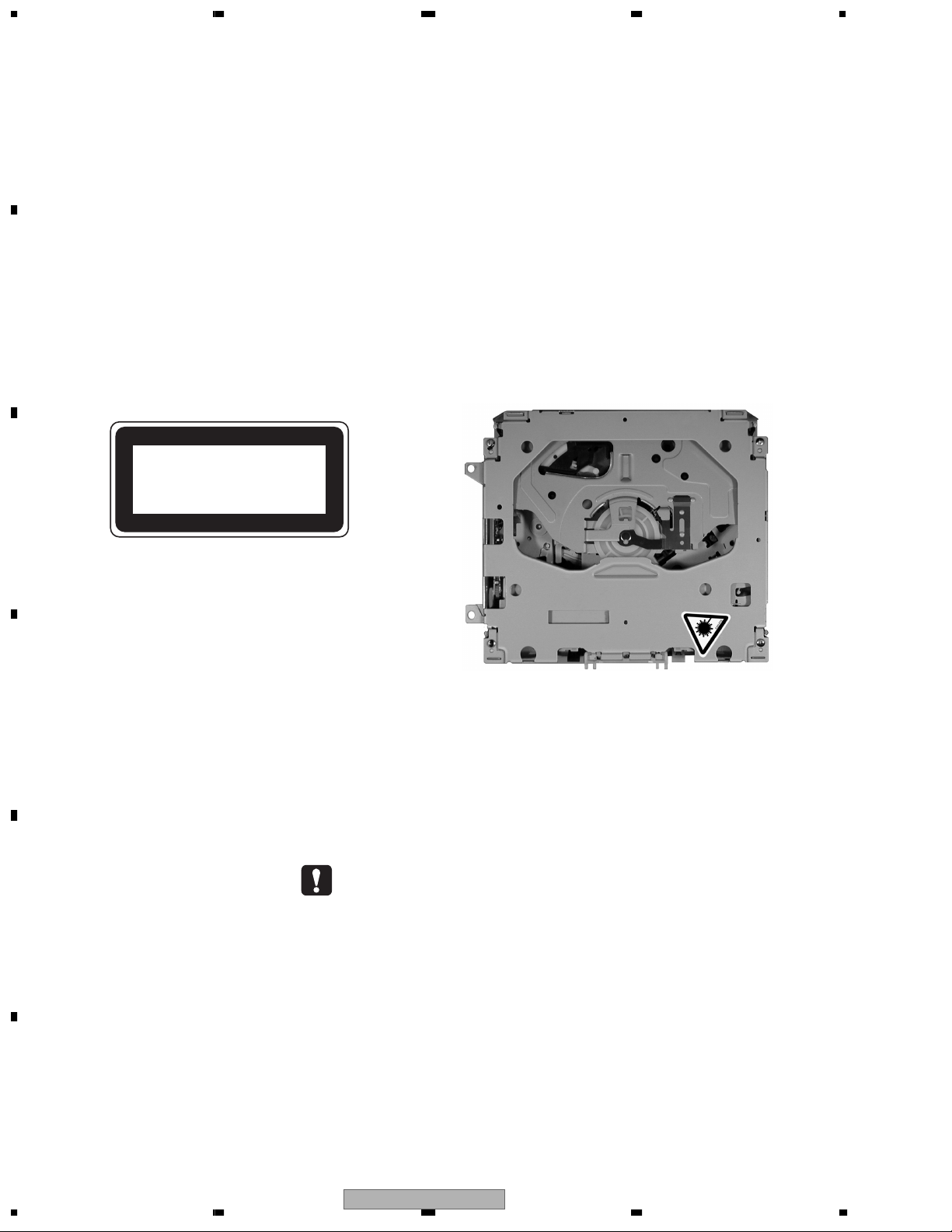
2. A “CLASS 1 LASER PRODUCT” label is affixed to the
bottom of the player.
3. The triangular label is attached to the mechanism
unit frame.
CLASS 1
LASER PRODUCT
C
4. Specifications of Laser Diode
D
Specifications of laser radiation fields to which human access is possible during service.
Wavelength = 800 nanometers
- CD Player Service Precautions
1. Before disassembling the unit, be sure to turn off the
E
F
power. Unplugging and plugging the connectors during power-on mode may damage the ICs inside the
unit.
2. To protect the pickup unit from electrostatic discharge during serviving, take an appropriate treatment(shorting-solder) by referring to "the DISASSEMBLY" on page 54.
2
1234
3. After replacing the pickup unit, be sure to check
the grating.(See p.51.)
DEH-P3600MP/XM/EW
5678
[ Important symbols for good services ]
In this manual, the symbols shown-below indicate that adjustments, settings or cleaning should be made securely.
When you find the procedures bearing any of the symbols, be sure to fulfill them:
1. Product safety
You should conform to the regulations governing the product (safety, radio and noise, and other regulations), and
should keep the safety during servicing by following the safety instructions described in this manual.
2. Adjustments
To keep the original performances of the product, optimum adjustments or specification confirmation is indispensable.
In accordance with the procedures or instructions described in this manual, adjustments should be performed.
3. Cleaning
For optical pickups, tape-deck heads, lenses and mirrors used in projection monitors, and other parts requiring cleaning,
proper cleaning should be performed to restore their performances.
4. Shipping mode and shipping screws
To protect the product from damages or failures that may be caused during transit, the shipping mode should be set or
the shipping screws should be installed before shipping out in accordance with this manual, if necessary.
A
B
5. Lubricants, glues, and replacement parts
Appropriately applying grease or glue can maintain the product performances. But improper lubrication or applying
glue may lead to failures or troubles in the product. By following the instructions in this manual, be sure to apply the
prescribed grease or glue to proper portions by the appropriate amount.For replacement parts or tools, the prescribed
ones should be used.
C
D
56
DEH-P3600MP/XM/EW
E
F
7
8
3

1234
CONTENTS
SAFETY INFORMATION.....................................................................................................................................2
A
B
C
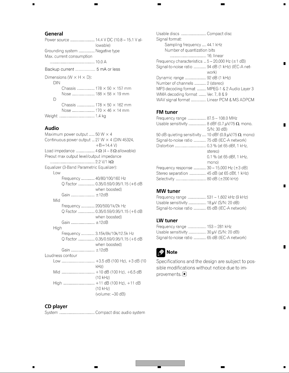
1. SPECIFICATIONS............................................................................................................................................ 5
2. EXPLODED VIEWS AND PARTS LIST............................................................................................................6
2.1 PACKING ................................................................................................................................................... 6
2.2 EXTERIOR................................................................................................................................................. 8
2.3 CD MECHANISM MODULE.....................................................................................................................12
3. BLOCK DIAGRAM AND SCHEMATIC DIAGRAM..........................................................................................14
3.1 BLOCK DIAGRAM................................................................................................................................... 14
3.2 OVERALL CONNECTION DIAGRAM(GUIDE PAGE).............................................................................. 16
3.3 KEYBOARD UNIT.................................................................................................................................... 22
3.4 CD MECHANISM MODULE(GUIDE PAGE)............................................................................................24
4. PCB CONNECTION DIAGRAM .....................................................................................................................34
4.1 TUNER AMP UNIT...................................................................................................................................34
4.2 PANEL UNIT ............................................................................................................................................ 38
4.3 KEYBOARD UNIT.................................................................................................................................... 39
4.4 CD CORE UNIT(S10WMA)......................................................................................................................40
5. ELECTRICAL PARTS LIST ............................................................................................................................42
6. ADJUSTMENT ............................................................................................................................................... 49
6.1 CD ADJUSTMENT................................................................................................................................... 49
6.2 CHECKING THE GRATING AFTER CHANGING THE PICKUP UNIT....................................................51
6.3 ERROR MODE ........................................................................................................................................ 53
7. GENERAL INFORMATION............................................................................................................................. 54
7.1 DIAGNOSIS............................................................................................................................................. 54
7.1.1 DISASSEMBLY..................................................................................................................................... 54
7.1.2 CONNECTOR FUNCTION DESCRIPTION.......................................................................................... 57
7.2 PARTS...................................................................................................................................................... 58
7.2.1 IC ..........................................................................................................................................................58
7.2.2 DISPLAY ............................................................................................................................................... 67
7.3 OPERATIONAL FLOW CHART...............................................................................................................69
7.4 CLEANING............................................................................................................................................... 70
8. OPERATIONS ................................................................................................................................................71
D
E
F
4
1234
DEH-P3600MP/XM/EW
5678
1. SPECIFICATIONS
A
B
C
D
E
56
DEH-P3600MP/XM/EW
F
7
8
5
N
1234
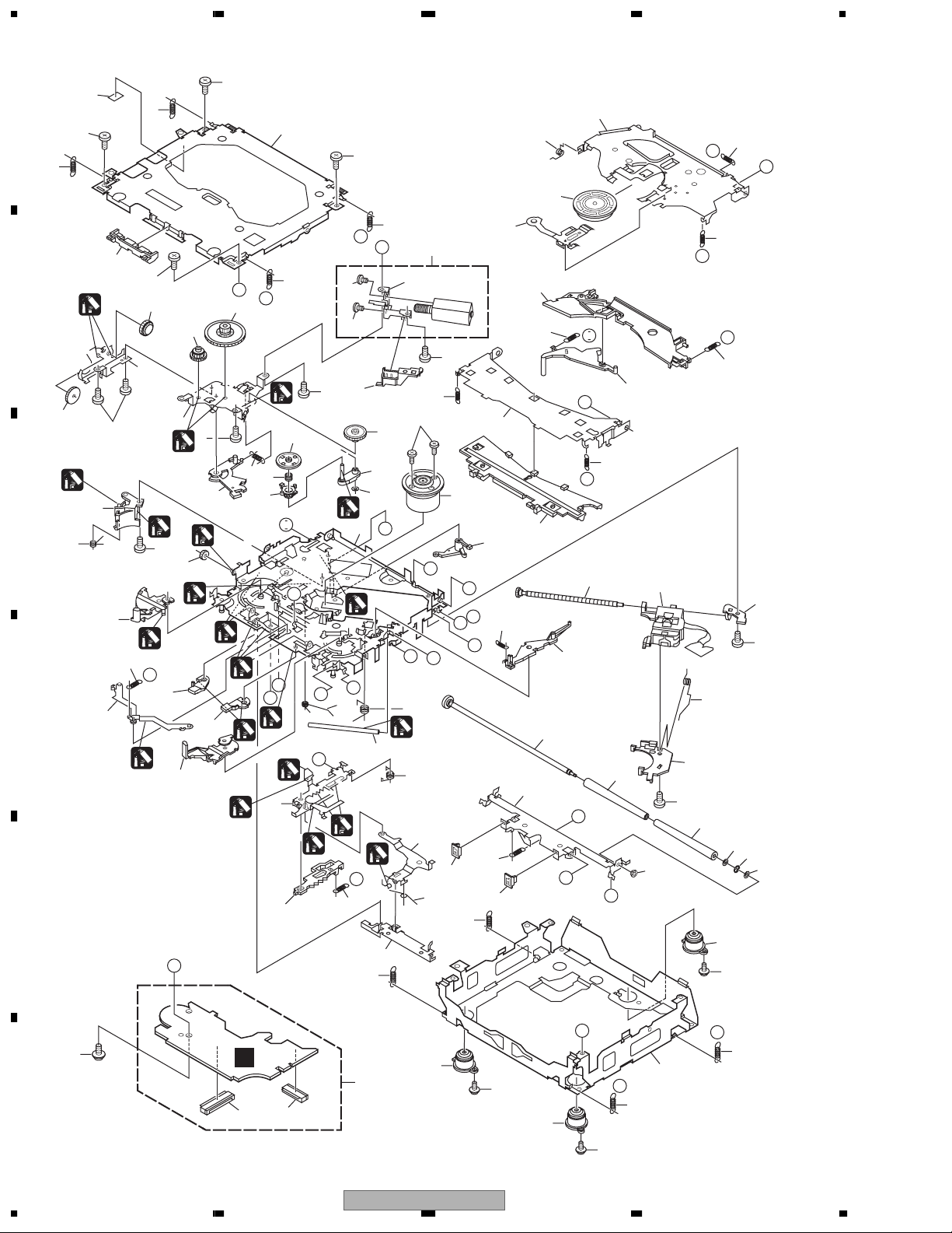
2. EXPLODED VIEWS AND PARTS LIST
OTES : • Parts marked by " * " are generally unavailable because they are not in our Master Spare Parts List.
A
• Screw adjacent to mark on the product are used for disassembly.
"
• For the applying amount of lobricants or glue, follow the instructions in this manual.
(In the case of no amount instructions,apply as you think it appropriate.)
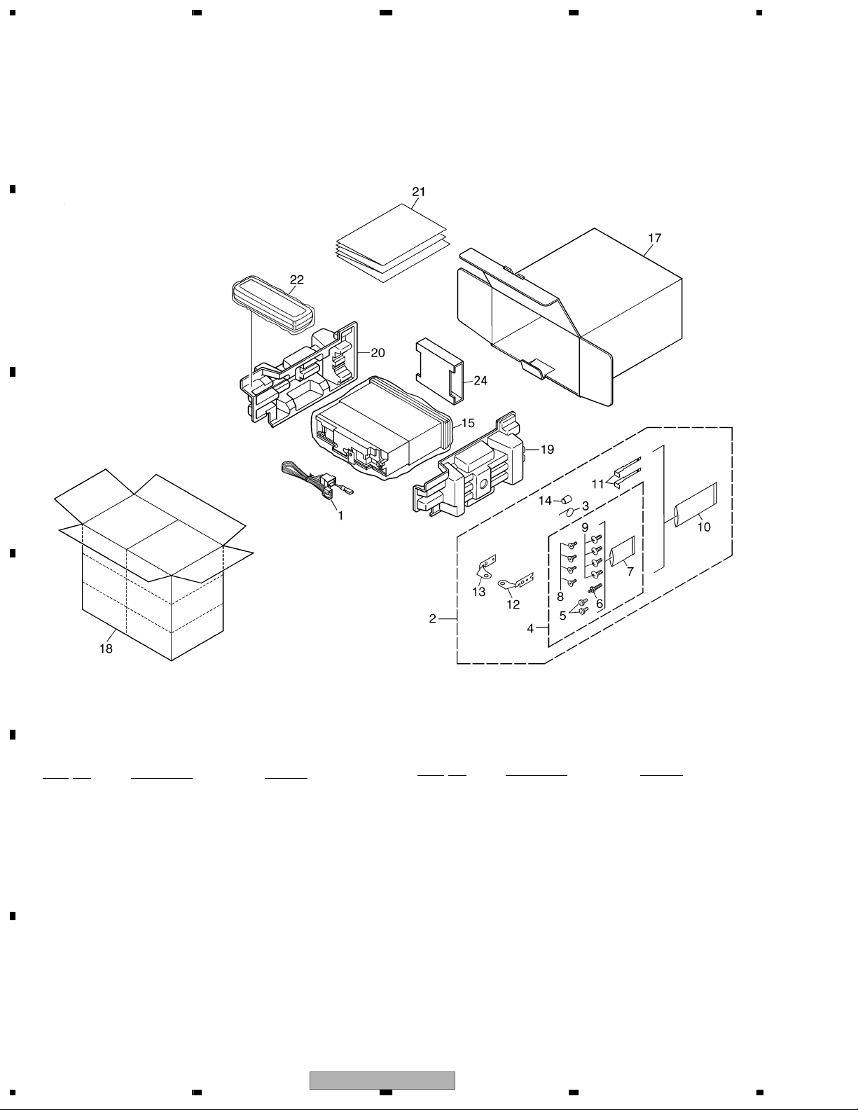
2.1 PACKING
B
C
D
(1) PACKING SECTION PARTS LIST
Mark No. Description Part No.
1 Cord Assy CDE7059
2 Accessory Assy CEA3376
3 Spring CBH1650
E
4 Screw Assy CEA3848
5 Fixing Screw BPZ20P060FZK
6 Screw CBA1650
* 7 Polyethylene Bag CEG-127
8 Screw CRZ50P090FTC
9 Screw TRZ50P080FTC
* 10 Polyethylene Bag CEG-158
11 Handle CNC5395
F
12 Holder CND1249
13 Holder CND1250
14 Bush CNV3930
15 Polyethylene Bag CEG-162
6
1234
Mark No. Description Part No.
16 •••••
17 Carton See Contrast table(2)
18 Contain Box See Contrast table(2)
19 Protector CHP2663
20 Protector CHP2664
21-1 Owner's Manual XRD7024
21-2 Owner's Manual XRD7025
21-3 Owner's Manual XRD7026
21-4 Installation Manual XRD7027
* 21-5 Warranty Card CRY1157
* 21-6 Passport CRY1013
22 Case Assy CXB3520
23 •••••
24 Inner Box XHW7001
DEH-P3600MP/XM/EW
- Owner's Manual, Installation Manual
Model
DEH-P3600MP/XM/EW
DEH-P3600MPB/XM/EW
DEH-P3630MP/XM/EW
Parts No.
XRD7024
XRD7025
XRD7026
XRD7027
Language
English, Spanish
German, French
Italian, Dutch
English, Spanish, German, French, Italian, Dutch
(2) CONTRAST TABLE
DEH-P3600MP/XM/EW, DEH-P3600MPB/XM/EW and DEH-P3630MP/XM/EW are constructed the same
except for the following:
Mark No. Symbol and Description
1718Carton
Contain Box
DEH-P3600MP/XM/EW
XHG7012
XHL7012
DEH-P3600MPB/XM/EW
XHG7014
XHL7014
Parts No.
DEH-P3630MP/XM/EW
XHG7015
XHL7015
5678
A
B
C
D
E
56
DEH-P3600MP/XM/EW
F
7
8
7
1234
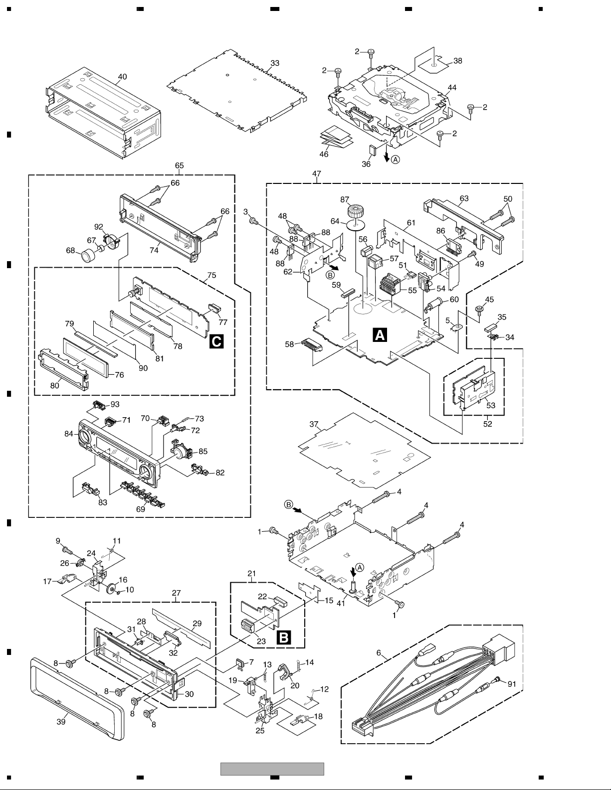
2.2 EXTERIOR
A
B
C
D
E
F
8
1234
DEH-P3600MP/XM/EW

5678
(1) EXTERIOR SECTION PARTS LIST
Mark No. Description Part No.
1 Screw BMZ30P040FZK
2 Screw BSZ26P060FTC
3 Screw BSZ30P060FTC
4 Screw BSZ30P200FTC
5 Terminal(CN402) VNF1084
6 Cord Assy CDE7059
7 Button(EJECT) CAC7752
8 Screw(M2x4.5) CBA1647
9 Screw(M2x4) CBA1649
10 Washer CBF1038
11 Spring CBH2650
12 Spring CBH2651
13 Spring CBH2652
14 Spring CBH2653
15 Holder CND1254
16 Gear CNV5997
17 Arm CNV7400
18 Arm CNV7401
19 Arm CNV7402
20 Arm CNV7403
21 Panel Unit CWM8758
22 Socket(CN1950) CKS3550
23 Connector(CN1951) CKS4806
24 Holder Unit CXB9501
25 Holder Unit CXB9502
26 Damper Unit CXB9503
27 Service Panel Unit See Contrast table(2)
28 Spring CBL1512
29 Cover CNM6854
30 Panel See Contrast table(2)
31 Pin CNV6486
32 Lighting Conductor CNV6487
33 Case CNB2870
34 Earth Plate CNC8915
35 Cushion CNM8890
36 Insulator CNM7682
37 Insulator CNM7935
38 Insulator CNM8174
39 Panel See Contrast table(2)
40 Holder Unit CXB6681
41 Chassis Unit See Contrast table(2)
42,43 •••••
44 CD Mechanism Module(S10CODE2)CXK5665
45 Screw ISS26P055FTC
46 Cable CDE7189
No. Description Part No.
Mark
52 FM/AM Tuner Unit CWE1645
53 Holder CND1054
54 Pin Jack(CN352) CKB1051
55 Plug(CN981) CKM1376
56 Connector(CN801) CKS4124
57 Connector(CN101) CKS3408
58 Plug(CN831) CKS3537
59 Connector(CN721) CKS3837
60 Antenna Jack(CN401) CKX1056
61 Holder CND1325
62 Holder CND1352
63 Heat Sink CNR1668
64 Insulator XNM7031
65 Detachable Assy See Contrast table(2)
66 Screw BPZ20P100FZK
67 Spring CBL1470
68 Knob XAA7003
69 Button(1-6) XAC7005
70 Button(LOUD) XAC7020
71 Button(PAUSE) XAC7019
72 Button(OPEN) See Contrast table(2)
73 Spring XBH7001
74 Cover See Contrast table(2)
75 Keyboard Unit See Contrast table(2)
76 LCD(LCD1901) See Contrast table(2)
77 Connector(CN1901) CKS4524
78 Sheet XNM7006
79 Connector XNV7006
80 Holder XNC7002
81 Lighting Conductor XNV7005
82 Button(BAND) XAC7021
83 Button(EQ) XAC7022
84 Sub Grille Assy See Contrast table(2)
85 Sub Button Assy(SELECT) XXA7228
86 IC(IC301) PAL007A
87 Choke Coil(L981) CTH1280
88 Transistor(Q752,901,911) 2SD2375
89 •••••
90 Sheet See Contrast table(2)
91 Cap CKX-003
* 92 Lighting Conductor XNV7012
93 Button(TA) See Contrast table(2)
A
B
C
D
E
47 Tuner Amp Unit XWM7022
48 Screw ASZ26P060FTC
49 Screw BPZ26P080FTC
50 Screw BSZ26P160FTC
51 Fuse(10A) CEK1208
56
DEH-P3600MP/XM/EW
F
7
8
9
1234
(2) CONTRAST TABLE
DEH-P3600MP/XM/EW, DEH-P3600MPB/XM/EW and DEH-P3630MP/XM/EW are constructed the same
except for the following:
A
Parts No.
Mark No. Symbol and Description
Service Panel Unit
27
Panel
30
Panel
39
Chassis Unit
41
Detachable Assy
65
DEH-P3600MP/XM/EW
CXX1691
CNS7245
XNS7070
XXA7186
XXA7129
DEH-P3600MPB/XM/EW
CXX1694
CNS7310
CNS6333
XXA7187
XXA7131
DEH-P3630MP/XM/EW
CXX1694
CNS7310
CNS6333
XXA7188
XXA7130
Button(OPEN)
72
Cover
74
Keyboard Unit
B
C
D
75
LCD(LCD1901)
76
Sub Grille Assy
84
Sheet
90
Button(TA)
93
XAC7012
XNS7013
XWM7028
XAW7003
XXA7144
Not used
XAC7027
XAC7046
XNS7058
XWM7030
XAW7001
XXA7146
XNM7007
XAC7028
XAC7046
XNS7058
XWM7029
XAW7003
XXA7145
Not used
XAC7028
E
F
10
1234
DEH-P3600MP/XM/EW

5678
A
B
C
D
E
56
DEH-P3600MP/XM/EW
F
7
8
11
1234
2.3 CD MECHANISM MODULE
A
13
5
13
42
5
81
34
5
15
22
E
F
93
13
A
44
B
5
B
1
54
C
52
53
13
D
86
86
82
83
4
37
71
4
29
51
1
73
50
72
10
1
I
76
B
55
4
36
4
1
18
2
24
47
7
C
64
2
1
61
2
M
1
23
87
75
E
63
57
62
58
1
G
L
1
N
R
1
1
2
1
40
56
D
O
16
P
1
33
1
P
19
J
12
3
20
39
1
69
30
2
21
M
D
79
2
1GEM1024
2GEM1045
3GEM1035
E
92
26
G
68
28
I
H
28
45
J
38
23
K
59
49
F
Q
A
27
H
77
90
48
8
67
17
78
25
70
60
80
N
L
K
43
46
6
60
11
89
10
14
74
R
31
41
85
C
91
F
D
3
65
1
2
85
66
35
O
31
Q
14
85
12
DEH-P3600MP/XM/EW
1234

5678
CD MECHANISM MODULE SECTION PARTS LIST
Mark No. Description Part No.
1 CD Core Unit(S10WMA) CWX2851
2 Connector(CN101) CKS4182
3 Connector(CN901) CKS4017
4 Screw BMZ20P035FTC
5 Screw BSZ20P040FTC
6 Screw(M2x4) CBA1362
7 Screw(M2x3) CBA1511
8 Screw(M2x3) CBA1527
9 •••••
10 Washer CBF1038
11 Washer CBF1060
12 Spring CBH2390
13 Spring CBH2606
14 Spring CBH2607
15 Spring CBH2608
16 Spring CBH2609
17 Spring CBH2610
18 Spring CBH2735
19 Spring CBH2612
20 Spring CBH2613
21 Spring CBH2614
22 Spring CBH2615
23 Spring CBH2616
24 Spring CBH2617
25 Spring CBH2620
26 Spring CBH2621
27 Spring CBH2641
28 Spring CBH2642
29 Spring CBH2643
30 Spring CBH2659
31 Spring CBH2688
32 •••••
33 Shaft CLA4441
34 Frame CNC9962
35 Frame CNC9963
36 Bracket CNC9966
37 Bracket CND1895
38 Arm CNC9968
39 Arm CND1909
40 Lever CND2032
41 Lever CNC9984
42 Sheet CNM8134
43 Collar CNV7798
44 Guide CNV7799
45 Arm CNV7800
No. Description Part No.
Mark
51 Gear CNV7208
52 Gear CNV7209
53 Gear CNV7210
54 Gear CNV7211
55 Gear CNV7212
56 Rack CNV7214
57 Arm CNV7215
58 Arm CNV7216
59 Guide CNV7217
60 Roller CNV7218
61 Gear CNV7219
62 Arm CNV7221
63 Arm CNV7220
64 Arm CNV7222
65 Damper CNV7313
66 Damper CNV7314
67 Arm CNV7341
68 Arm CNV7342
69 Guide CNV7360
70 Guide CNV7361
71 Holder CNV7437
72 Arm CNV7805
73 Gear CNV7595
74 Damper CNV7618
75 Motor Unit(M1) CXB6007
76 Chassis Unit CXC2318
77 Screw Unit CXB8729
78 Gear Unit CXC2397
79 Arm Unit CXC2316
80 Arm CND1896
81 Arm CND1894
82 Motor Unit(M2) CXB8933
83 Bracket CNC9985
84 •••••
85 Screw(M2x5) EBA1028
86 Screw JFZ20P020FTC
87 Screw JGZ17P022FTC
88 •••••
89 Washer YE20FTC
90 Pickup Unit(P10)(Service) CXX1641
91 Screw IMS26P030FTC
92 Spring CBL1635
93 Clamper CNV7197
A
B
C
D
E
46 Rack CNV7199
47 Holder CNV7201
48 Holder CNV7202
49 Arm CNV7203
50 Gear CNV7207
56
DEH-P3600MP/XM/EW
F
7
8
13
Q
Q
Q
8
S
K
O
A
S
D
1234
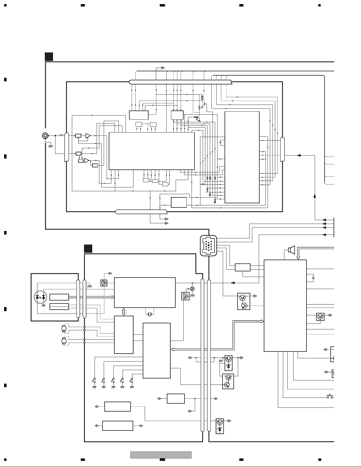
3. BLOCK DIAGRAM AND SCHEMATIC DIAGRAM
3.1 BLOCK DIAGRAM
A
TUNER AMP UNIT
A
VDD
FM/AM TUNER UNIT
B
ANTENNA
CN401
1
2
1
3
AM ANT
FM ANT
ATT
ATT
ANT adj
FMRF
FMRF
RF adj
7 6 13 5 10 9 8 11 14 18 19 20 21
WC
CE2
ROM_VDD
IC 3 EEPROM
5.0V
OSC
LPF
IC 1
3.3V
MIXER, IF AMP
T51
CF52
C
RFGND
OSCGND
DGND
212 1522 16 4 17
CD CORE UNIT(S10WMA)
D
PICKUP UNIT
D
E
(P10)(SERVICE)
LASER
DIODE
HOLOGRAM
UNIT
FOCUS ACT.
TRACKING ACT.
MONITOR
DIODE
SPINDLE
MOTOR
CARRIAGE
LOAD/
MOTOR
Q101
AC,BD
F,E
12EJ
SENSE
V3R3D
142
LD
143
PD
DIGITAL SERVO / DATA PROCESSOR
TD/FD
12
FOP
13
TOP
DRIVER
16
SOP
15
SOM
18
LCOP
17
LCOM
IC 301
BA5835FM
8EJ
SENSE
SENSE
3
IC 203
NJM2391DL1-33
CN101
LD-
15
15
MD
5
5
FOP
FO+
1
1
TO+
TOP
4
4
LD+
14
14
M
M
CLAMP
SENSE
V3R3D
+3.3V REGULATOR
5
F
V1R5
IC 501
S-L2980A15MC-C6A
AUDIOGNDNCVCC
IC 201
UPD63761GJ
RF-AMP,CD DECODER,
MP3 and WMA DECODER,
DISC
SD/MD
CD
LOEJ
CONT
HOME
53
22
9
47
32
31
30
97
1
VD2
1,3
X201
CD CONTROLLER
LOEJ
CONT
4
CLAMP
12EJ
8EJ
DSCSNS
HOME
V3R3D
3534
IC 701
PE5402A
3VDD
DI
SL
IC 5
←
5V 3.3V
CF51
IC 4
3.3V 2.5V
3.3V
VDD_3.3
TUN 3.3V
SYS 8V
31
LOUT
55
CDMUTE
BRST,BRXEN,BSRQ
BDATA,BSCK
49
VDCONT
+3.3V REGULATOR
3
IC 703
S-812C33AUA-C2N
CK
←
MUTE
Q603
CN901
L-OUT
Q601
VDCONT
LDET
VD2
DO
RDS_CK
RDS_HSLK
RDS_DATA
RDS_LOCK
Rch
IC 2
2.5V
DET, FM MPX,
RDS DECODER
BUS+L
BUS-L
CN101
7
11
5
1
8
IP-BUS DRIVER
BUS-
5
IC 101
6
HA12240FP
BUS+
CN721
10
14
Q101
Q102
BRST,BRXEN,BSRQ
BDATA,BSCK
VD
3
20
21
4
19
5
19
22
2
Q752
VD
Q751
5
VDD
1
Q754
VD
BU
8
IPPW
86
TX
1
RX
2
85
24
BU
71
24
Lch
23
BUZZER
100
PEE
TX
RX
IPPW
SYSTEM CONTROLLER
ASENBO
IC 601(2/2)
PE5406A
DPDT
KYDT
dsens
1
96
95
90
SYSPW
STRKEY2
STRKEY1
AVREF
FLPILM
ejectin
swvdd
ILMPW
20
mute
adpw
X1
X2
TUN L
BUS+L
BUS-L
CD L
EVST,EVCK,EVDT
37
16
X601
15
21
58
75
83
22
9
8
Q601
BU
VDD
DETACH SEN
RDS_D
RDS_H
RDS_C
RDS_L
3
5
6
4
V
S
CE1
2.5V
VD
2
VDD
1.5V REGULATOR
14
1234
DEH-P3600MP/XM/EW
P
t
5678
A
RESET
1
11
32
99
94
98
97
88
74
tunpce@
TUNPCE
TUNPDI
TUNPDO
TUNPCK
ldet
SL
reset
CE2
CE1
DO
DI
CK
SYSTEM CONTROLLER
IC 601(1/2)
PE5406A
Q401
TUN L
BUS+L
BUS-L
CD L
EVST,EVCK,EVDT
RDS_DATA
RDS_HSLK
RDS_CK
RDS_LOCK
ELECTRONIC VOLUME/
SOURCE SELECTOR
3
IN2-L
5
IN4+L
6
IN4-L
4
IN3-L
Q402
IC 131
PML003AM
45
RDT
42
RDS57K
89
rck
44
rdslk
10
FL
11
RL
BU
37
te
16
X1
X601
15
X2
21
W
58
Y2
75
Y1
Q601
83
EF
22
pw
9
LM
8
in
BU
VDD
Q961
CN831
BU
Q831
DGND
5
5
6
6
8
8
9
9
ILB
7
7
10
S1970
EJECT
B
4
5
2
IC 651
BD4834G
DALMON
bsens
asens
MUTE
Q502
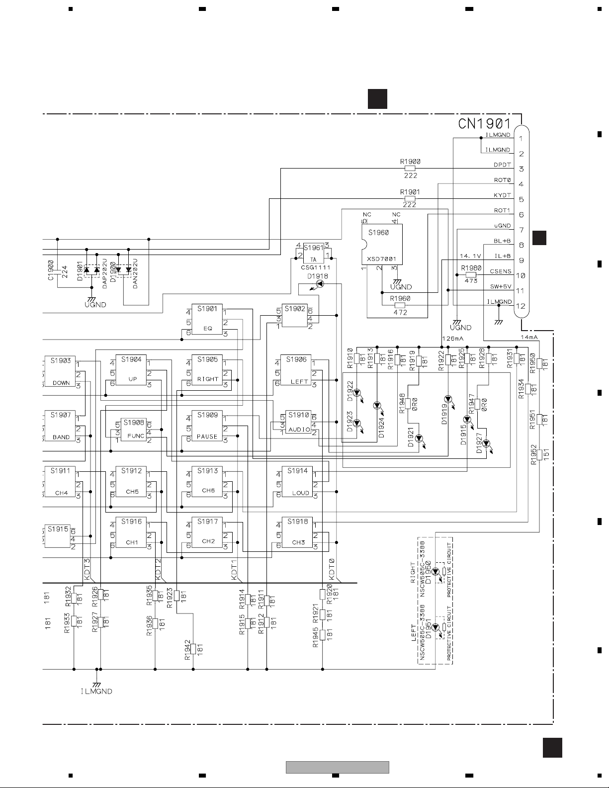
PANEL UNIT
CN1901
ILB
9
BL+B
810
VDD
VDD REGULATOR
VDD
10
93
92
Q901
BACKUP SENSE
Q931
Q902
BU
ACC
BU
ACC SENSE
BU
20
23
FL-
21
FL+
3
RL-
5
RL+
B.REMOTE
25
SYS 8V REGULATOR
Q911
Q912
Q913
SYSPW
IC 921
13
SYS 8V
MUTE
Q301
14
12
POWER AMP
IC 301
FLIN
PAL007A
RLIN
STBYMUTE
22 4
SYS 8V
TUNER 3.3V REGULATOR
TUN 3.3V
NJM2391DL1-33
KEYBOARD UNIT
C
CN352
2
FL
Q352
6
RL
Q351
B
CN981
FUSE
1
1
3
22
10
12
9
11
6
BU
CN801
3
KEYD
2
KEYAD
1
BACK UP
10A
3
ACC
C
D
10
12
9
11
6
BACK
GND
GND
FLFL+
RL-
RL+
B.REM
RR
RR
+
FR
REM
ACC
FR
+
-
B.
FL
FL
+
RL
RL
+
-
UP
E
VDD
DETACH SENSE
S831
Q971
Q962
SWDVDD
DPDT
KYDT
2
2
11
11
14
14
CN1951
CN1950
SWVDD
11
2
DPDT
3
10
KYDT
5
8
18
DPDT
20
KTDT
11
55
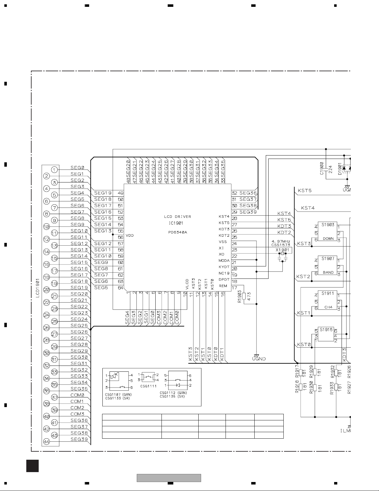
VDD
VLCD
LCD DRIVER/
KEY CONTROLLER
IC 1901
PD6340A
DEH-P3600MP/XM/EW
56
KEY DATA
7
KEY MATRIX
LCD
F
15
8
1234
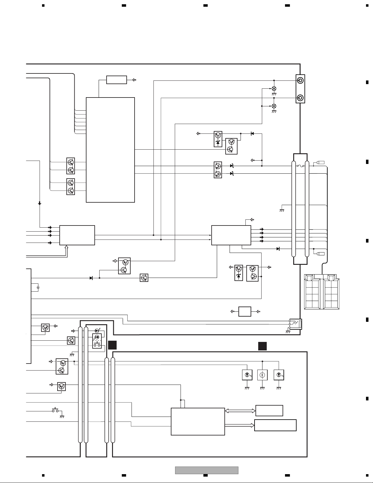
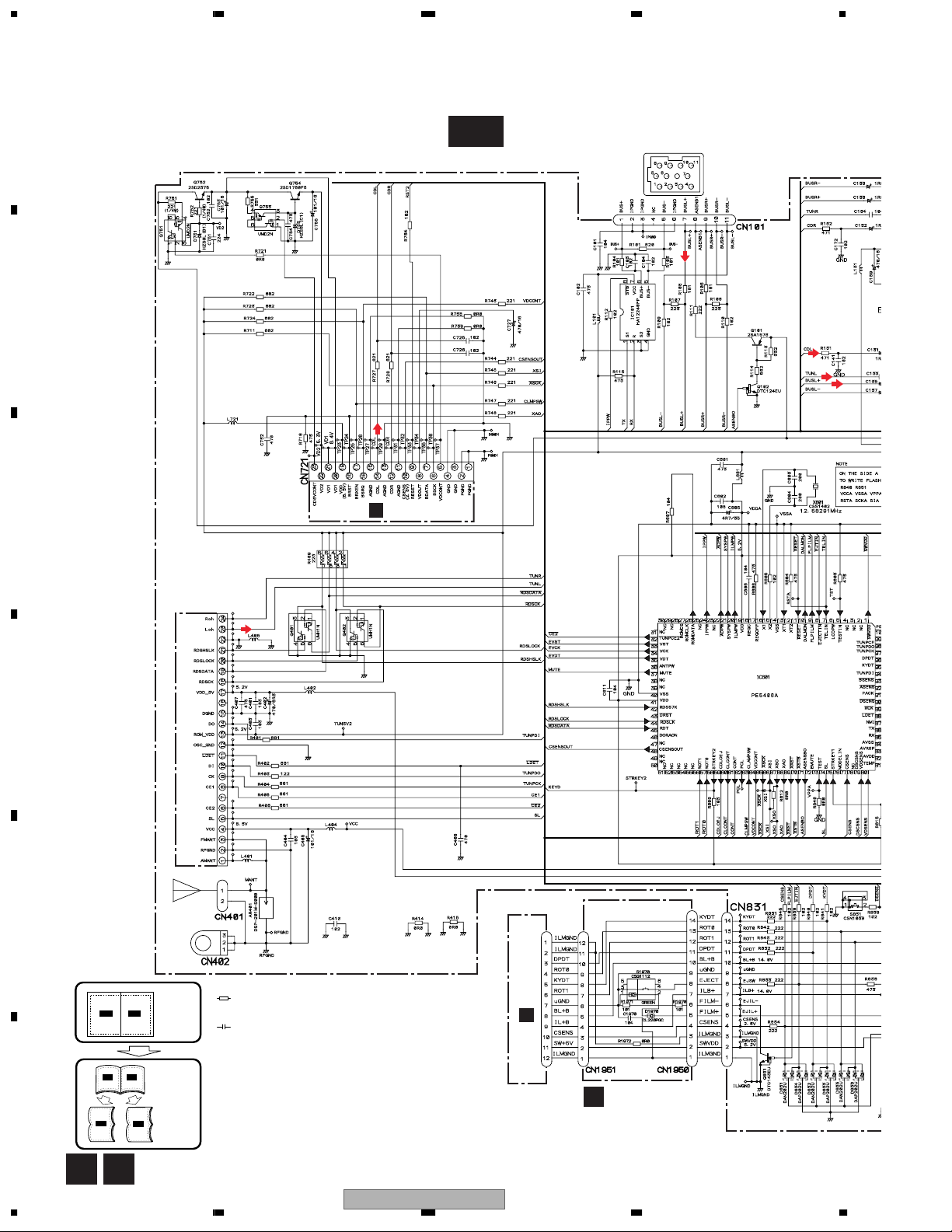
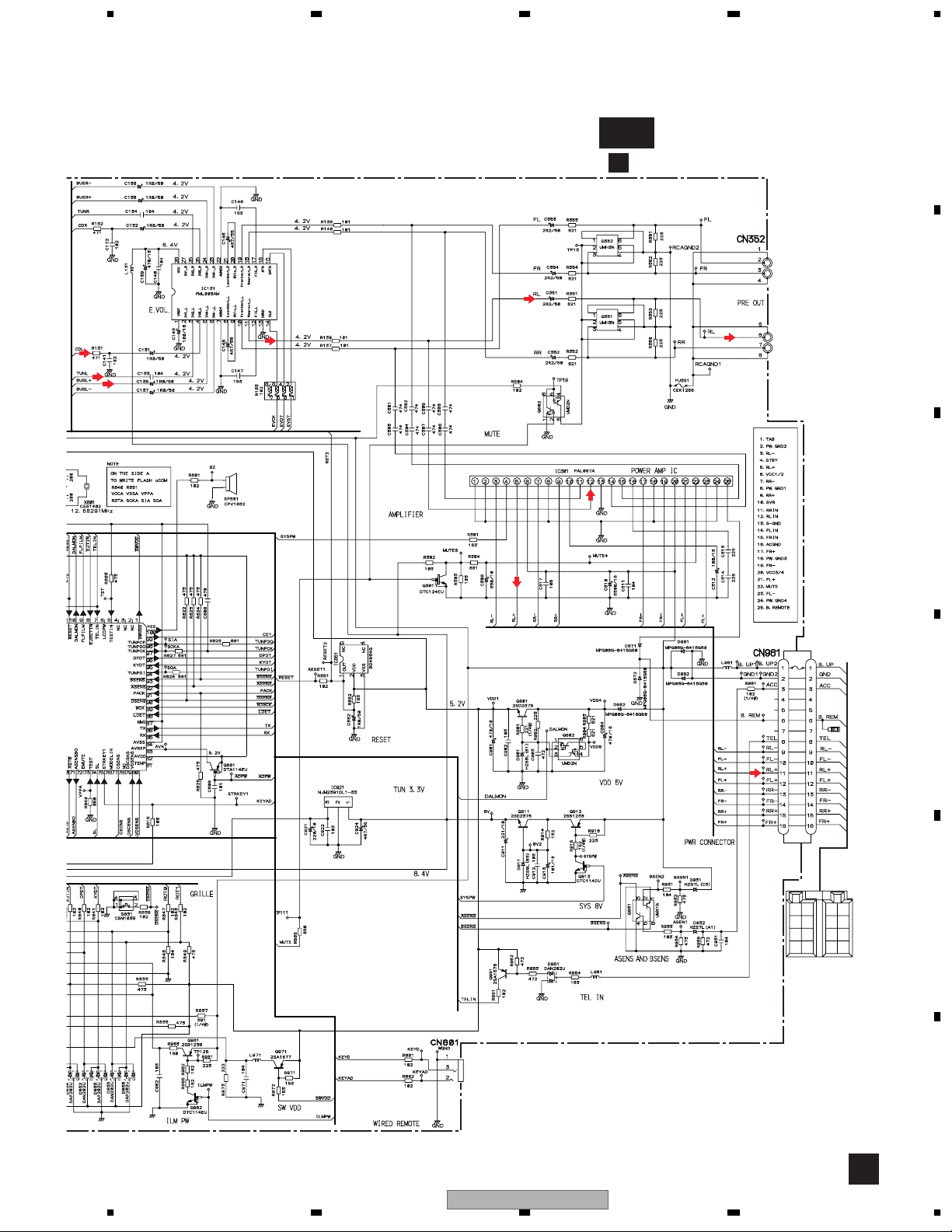
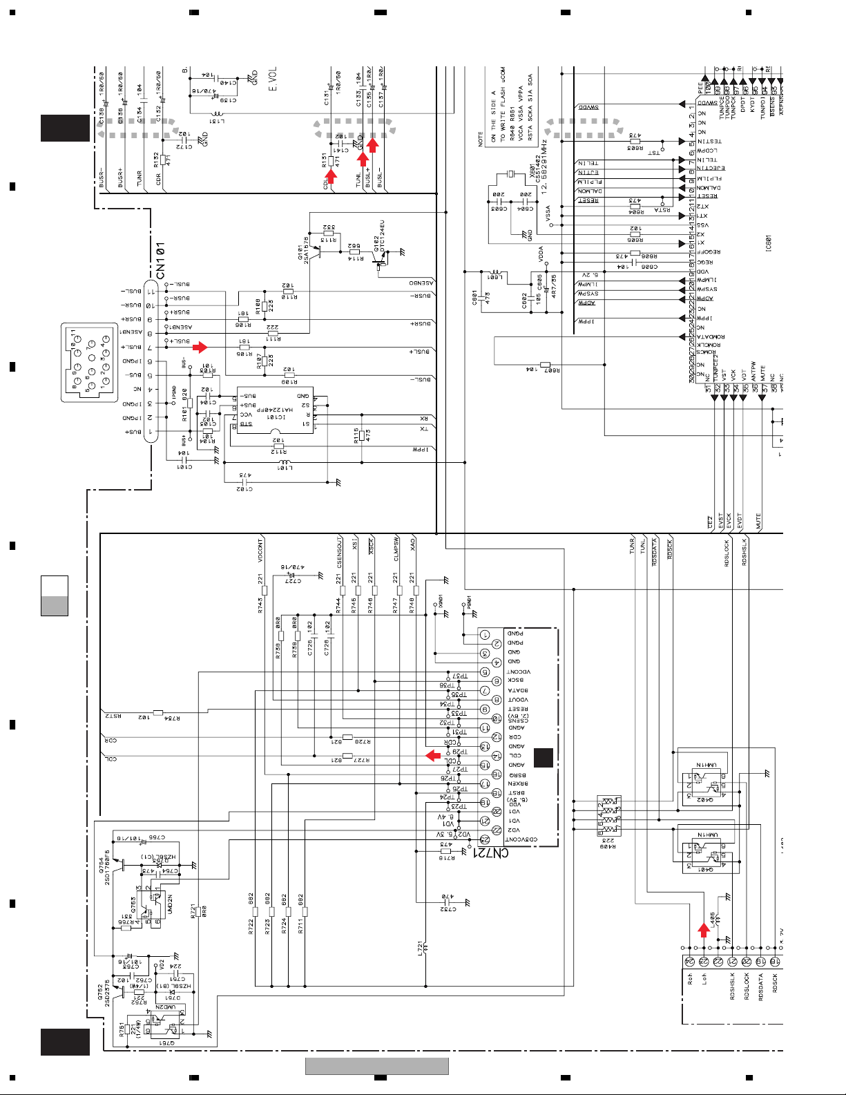
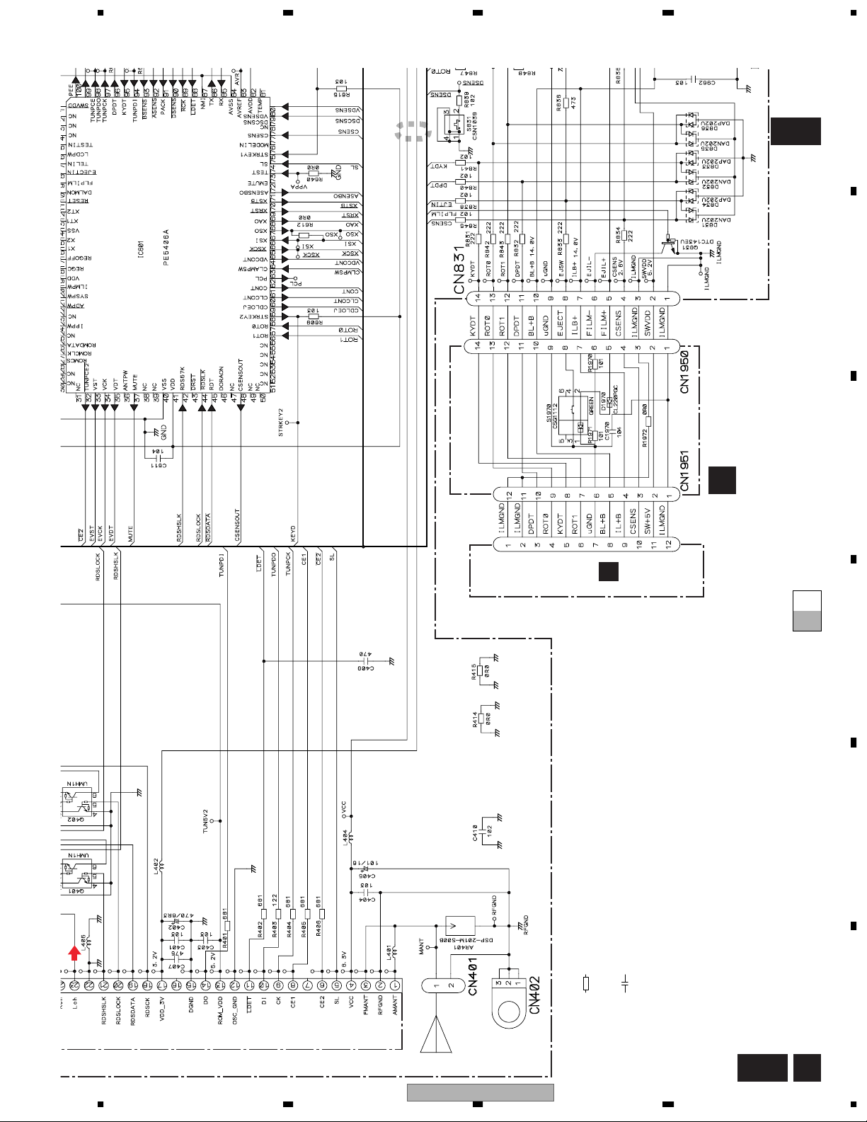
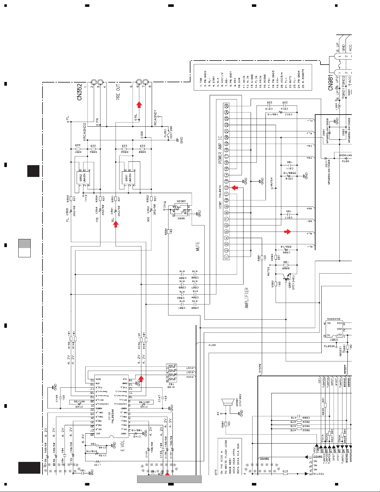
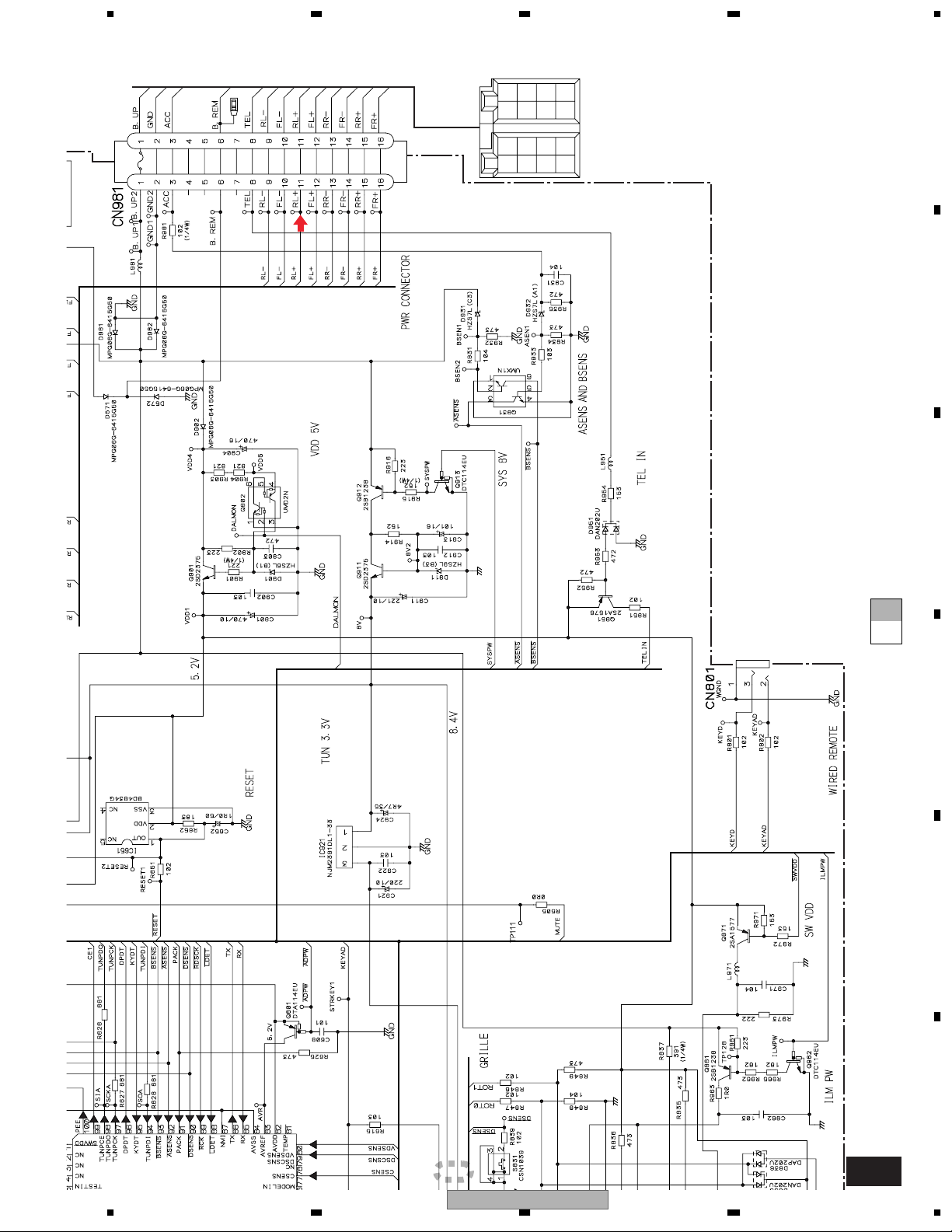
3.2 OVERALL CONNECTION DIAGRAM(GUIDE PAGE)
A
"ELECTRICAL PARTS LIST".
A-a
IP-BUS : 2.2dBs
B
CD : 0.0dBs
D
Note: When ordering service parts, be sure to refer to " EXPLODED VIEWS AND PARTS LIST" or
C
CN901
FM(100%) : -15.5dBs
AM(30%) : -26dBs
SYSTEM CONTROLLER
D
FM/AM TUNER UNIT
DETACH
SENSE
E
EJECT
NOTE :
Large size
A-b
A-b
SCH diagram
Guide page
Detailed page
A-a A-b
A-a
F
A-a
Symbol indicates a resistor.
No differentiation is made between chip resistors and
discrete resistors.
Symbol indicates a capacitor.
No differentiation is made between chip capacitors and
discrete capacitors.
For resistors and capacitors in the circuit diagrams, their resistance values or
capacitance values are expressed in codes:
Ex. *Resistors
Code Practical value
123 12k ohms
103 10k ohms
The > mark found on some component parts indicates
the importance of the safety factor of the part.
Therefore, when replacing, be sure to use parts of
identical designation.
*Capacitors
Code Practical value
103 0.01uF
101/10 100uF/10V
CN1901
C
B
PANEL UNIT
A B
16
1234
DEH-P3600MP/XM/EW
5678
A
A-b
A
TUNER AMP UNIT
FRONT
OUTPUT
FM : 7.6dBs
AM : -0.9dBs
CD : 10.1dBs
IP-BUS : 10.3dBs
3A
>
FM : 6.8dBs
AM : -1.7dBs
CD : 9.3dBs
IP-BUS : 9.5dBs
REAR
OUTPUT
B
LLER
DETACH
SENSE
600µH
CEK1208
FM : 33.6dBs
AM : 25.1dBs
CD : 36.1dBs
IP-BUS : 36.3dBs
C
10A
>
D
RR
RR
+
-
BACK
UP
ILL
GND
FR
FR
+
-
B.
FL
FL
REM
+
RL
RL
ACC
+
-
E
WIRED
REMOTE
CONTROL
DEH-P3600MP/XM/EW
56
F
A
7
8
17
1234
A
A-b
B
IP-BUS : 2.2dBs
21
3
SYSTEM CONTROLLER
C
A-b
A-a
A-a
D
CN901
D
E
CD : 0.0dBs
F
FM(100%) : -15.5dBs
AM(30%) : -26dBs
A-a
18
1234
DEH-P3600MP/XM/EW
5678
SYSTEM CONTROLLER
A
SENSE
DETACH
4
A-b
B
EJECT
CN1901
C
PANEL UNIT
B
A-b
A-a
A-a
*Capacitors
Code Practical value
103 0.01uF
101/10 100uF/10V
C
D
E
FM/AM TUNER UNIT
DEH-P3600MP/XM/EW
56
Symbol indicates a resistor.
No differentiation is made between chip resistors and
discrete resistors.
Symbol indicates a capacitor.
No differentiation is made between chip capacitors and
discrete capacitors.
For resistors and capacitors in the circuit diagrams, their resistance values or
capacitance values are expressed in codes:
Ex. *Resistors
Code Practical value
123 12k ohms
NOTE :
103 10k ohms
A-a
7
8
The > mark found on some component parts indicates
the importance of the safety factor of the part.
Therefore, when replacing, be sure to use parts of
identical designation.
F
B
19
1234
A
>
10A
FRONT
OUTPUT
FM : 6.8dBs
AM : -1.7dBs
B
REAR
CD : 9.3dBs
IP-BUS : 9.5dBs
OUTPUT
>
3A
CEK1208
600µH
TUNER AMP UNIT
A
C
A-b
A-a
D
FM : 7.6dBs
AM : -0.9dBs
CD : 10.1dBs
E
IP-BUS : 10.3dBs
F
A-b
20
21
DEH-P3600MP/XM/EW
1234
3
10A
CEK1208
5678
+
+
+
+
RR
-
RR
>
FM : 33.6dBs
AM : 25.1dBs
CD : 36.1dBs
IP-BUS : 36.3dBs
600µH
FR
FR
BACK
RL
FL
-
-
-
RL
FL
B.
REM
ACC
UP
ILL
GND
A
B
WIRED
REMOTE
CONTROL
C
A-b
A-a
D
E
SENSE
DETACH
4
DEH-P3600MP/XM/EW
56
F
A-b
7
8
21
1234
3.3 KEYBOARD UNIT
A
B
C
*B
*D
D
E
*B
*B
*C
SRC-OFF
DEH-P3600MP/XM/EW
DEH-P3600MPB/XM/EW
DEH-P3630MP/XM/EW
F
*A
CL-195PG-CD
CL-195SR-CD
CL-195SR-CD
*B
CSG1107
CSG1133
CSG1133
*C
CSG1112
CSG1135
CSG1135
*D
XAW7003
XAW7001
XAW7003
C
22
1234
DEH-P3600MP/XM/EW
5678
A
C
KEYBOARD UNIT
B
CN1951
VOLUME
B
*B
*B
*B
*C
SRC-OFF
*A
*B
*B
*C
*B
*B
*C
SCRL
*B
*C
C
*A
*A
*A
*A
*A
*A
*A
D
*B
*B
*B
*B
*B
*B
56
DEH-P3600MP/XM/EW
E
F
C
7
8
23
 Loading...