

Pioneer DEH-3900MP User Manual
MAN-DEH-3900MP-GB.fm Page 1 Monday, January 15, 2007 3:45 PM
CD RDS Receiver
Operation Manual
DEH-3900MP
Visit www.pioneer.co.uk (or www.pioneer.eu)
to register your product
ENGLISH
MAN-DEH-3900MP-GB.fm Page 2 Monday, January 15, 2007 3:45 PM
Contents
Thank you for buying this Pioneer product
Please read through these operating instructions so you will know how to operate your
model properly. After you have finished reading the instructions, keep this manual in a
safe place for future reference.
Installation ............................................ 2
DIN Front/Rear-mount ............... ................. 2
DIN Front-mount ..................................... .... 2
* Installation with the rubbe r bush ........... 2
* Removing the Unit ................................ 3
DIN Rear-mount .......................................... 3
Fastening the front pan el ............................ 4
Connecting the Units ........................... 5
Before You Start ................................... 6
About this unit ......................................... .... 6
About WMA ................................ ................. 6
About MP3 .............................................. .... 6
Visit our website .......................................... 6
Protecting your unit from theft ..................... 7
* Removing the front panel ..................... 7
* Attaching the front panel ....................... 7
Operating this unit ............................... 7
What’s What .... ........................................ .... 7
* Head unit .............................................. 7
* Optional remote control ........................ 8
* LCD display .......................................... 8
Basic Operations .... ................................. .... 9
* Turning the unit on and
selecting a source ... .............................. 9
* Adjusting the volume ............................ 9
* Turning the unit off ..................... ........... 9
Tuner ............................. .............................. 9
* Listening to the radio ........................ .... 9
* Storing and recalling b roadcast
frequencies ................... ........................ 9
* Tuning in strong signals ...................... 10
* Storing the strongest broadcast
frequencies ................... ...................... 10
RDS .............................. ............................ 10
* Introduction of RDS oper ation ............ 10
* Switching the RDS display ................. 10
* Receiving PTY alarm br oadcasts ....... 10
* Selecting alternative freq uencies ...... .. 10
* Receiving traffic announ cements ....... 11
* PTY list ............................................. .. 11
Built-in Player ............. ............................... 12
* Playing a disc ..................................... 12
* Repeating play .............................. ..... 12
* Playing tracks in random order ........... 12
* Scanning tracks or folder s ...... ............ 13
* Pausing disc playback ........................ 1 3
* Using compression and BMX ............. 13
* Searching every 10 tracks in the
current disc or folder .. ......................... 13
* Displaying text information on disc ..... 13
Audio Adjustments .................................... 14
* Using balance adjustment .................. 14
* Using the equalizer .... ......................... 14
* Adjusting equalizer curves ................. 14
* Adjusting loudness ............................. 14
* Adjusting source levels .................. ..... 14
Other Functions ........................................ 15
* Adjusting initial settings ...................... 15
* Setting the FM tuning st ep ................. 15
* Switching Auto PI Seek ...................... 15
* Switching the auxiliary s etting ............ 1 5
* Multi language display s etting ............ 1 5
* Saving the battery consu mption ......... 15
* Sound muting ..................................... 16
Additional Information ....................... 16
Error messages ............................ ............ 16
Handling guideline of di scs and player ..... 17
Dual Discs .................. ............................... 17
WMA, MP3 and WAV files ........................ 17
* Example of a hierarchy ....................... 18
* Compressed audio compati bility ........ 18
Russian character chart ............................ 1 8
Specifications ................... ......................... 19
Installation
Notes
• Check all connectio ns and systems before fin al installation.
• Do not use unauthori zed parts. The use of un authorized parts may cause malfunctions.
• Consult with your dealer if install ation requires drilling of holes or other modifications of the
vehicle.
• Do not install this unit wh ere:
– it may interfere with operati on of the vehicle.
– it may cause injury to a pas senger as a result of a sudden stop.
• The semiconductor la ser will be damaged if it overheats. Install this unit away from hot
places such as near the heater outlet.
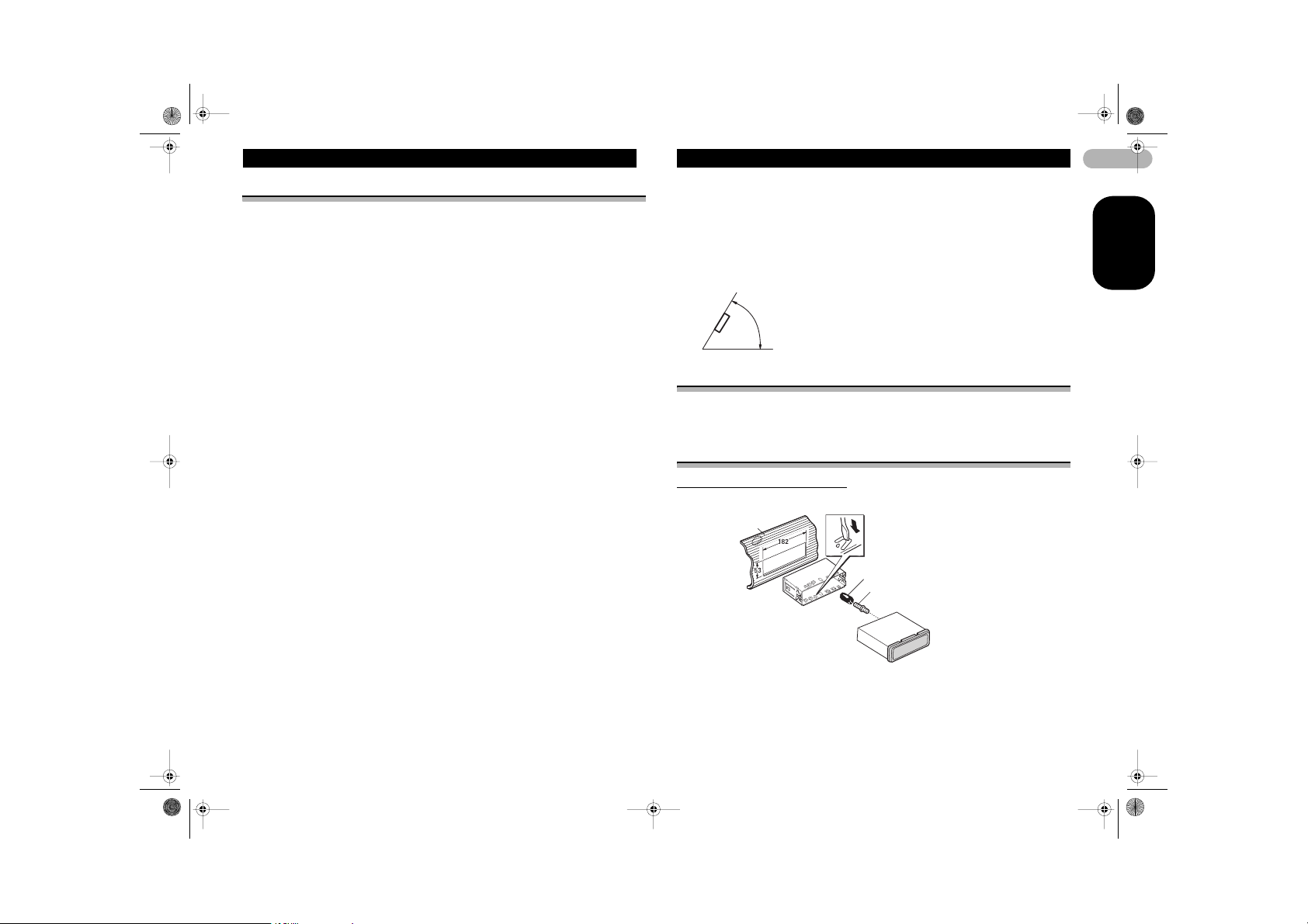
• Optimum performance i s obtained when the unit is installed at an angle of less than 60°.
60°
DIN Front/Rear-mount
This unit can be properly installed either from “Front” (conventional DIN Front-mount)
or “Rear” (DIN Rear-mount installation, utilizing threaded screw holes at the sides of
unit chassis). For details, refer to the following installation methods.
DIN Front-mount
Installation with the rubber bush
Dashboard
Mounting sleeve
Rubber bush
Screw
2
ENGLISH
MAN-DEH-3900MP-GB.fm Page 3 Monday, January 15, 2007 3:45 PM
Installation
1. Insert the mounting sleeve into the dashboard.
• When installing in a shallow space, use a supplied mounting sleeve. If there is
enough space behind the unit, use factory supplied mounting sleeve.
2. Secure the mounting sleeve by using a screwdriver to bend the metal tabs (90°)
into place.
3. Install the unit as illustrated.
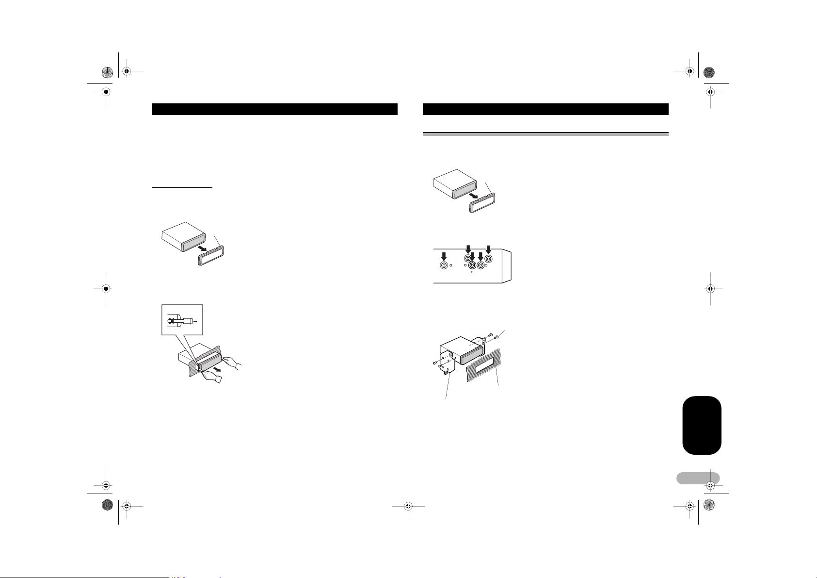
Removing the Unit
1. Extend top and botto m of the trim ring outwards to re move the trim ring. (When
reattaching the trim ring, point the side with a groove downwards and attach it.)
• It becomes easy to remove the trim ring if the front panel is released.
Trim ring
2. Insert the supplied extraction keys into both sides of the unit until they click into
place.
3. Pull the unit out of th e dashboard.
DIN Rear-mount
1. Extend top and bottom of the trim ring outwards to remove the trim ring. (When
reattaching the trim ring, point the side with a groove downwards and attach it.)
• It becomes easy to remove the trim ring if the front panel is released.
Trim ring
2. Determine the appropriate position where the holes on the bracket and the side
of the unit match.
3. Tighten two screws on each side.
• Use either truss screws (5 mm x 8 mm) or flush surface screws (5 mm x 9 mm),
depending on the shape of screw holes in the bracket.
Screw
Dashboard or Console
Factory radio mounting bracket
ENGLISH
3
MAN-DEH-3900MP-GB.fm Page 4 Monday, January 15, 2007 3:45 PM
Installation
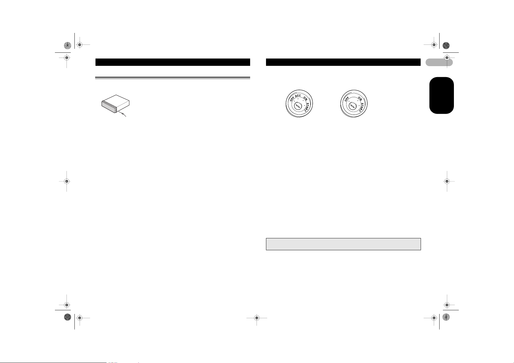
Fastening the front panel
If you do not plan to detach the front panel, the front panel can be fastened with
supplied scre w.
Screw
Connecting the Units
Notes
• When this unit is insta lled in a vehicle without A CC (accessory) position on the ignition
switch, red cable mu st be wired to the termina l that can detect the ope ration of the ignition
key. Otherwise, battery drain may result.
ACC position No ACC position
• Use this unit in other than the following conditi ons could result in fire or malfunction.
– Vehicles with a 12-volt battery and negative grounding.
– Speakers with 50 W (outpu t value) and 4 ohm to 8 ohm (impedance val ue).
• To prevent short-circuit, overheating or malfunction, be sure to follow the directions below.
– Disconnect the negative ter minal of the battery befo re installation.
– Secure the wiring with cable clamps or adhesive tape . To protect the wiring, wrap
adhesive tape around the m where they lie agains t metal parts.
– Place all cables away from moving parts, such as ge ar shift and seat rails.
– Place all cables away from hot places, such as ne ar the heater outlet.
– Do not pass the yellow cable thro ugh a hole into the engine compar tment to connect to a
battery.
– Cover any disconnected cab le connectors with ins ulating tape.
– Do not shorten any cables.
– Never cut the insulation of the po wer cable of this unit in order to share the power to other
equipment. Current capac ity of the cable is limit ed.
– Use a fuse of the rating pres cribed.
– Never wire the speaker negat ive cable directly to gr ound.
– Never band together mult iple speaker’s negati ve cables.
• Control signal is ou tput through blue/white cable when t his unit is powered on. Connect it to
an external power amp’s s ystem remote control or the v ehicle’s auto-antenna rel ay control
terminal (max. 300 m A, 12 V DC). If the vehicle i s equipped with a glas s antenna, connect
it to the antenna boo ster power supply termi nal.
• Never connect blue/wh ite cable to external po wer amp’s power terminal. Also, never
connect it to the power term inal of the auto antenna. Other wise, battery drain or malfunction
may result.
• Black cable is ground. Th is cable and other product’s ground cable (especia lly, high-current
products such as power amp) mus t be wired separately. Otherwise, fire or malfunction may
result if they are acc identally detached.
• Cord function may diff er according to the produc t, even if cord color is the same. When
connecting this syste m, be sure to check all ma nuals and connect co rds correctly.
4
ENGLISH
MAN-DEH-3900MP-GB.fm Page 5 Monday, January 15, 2007 3:45 PM
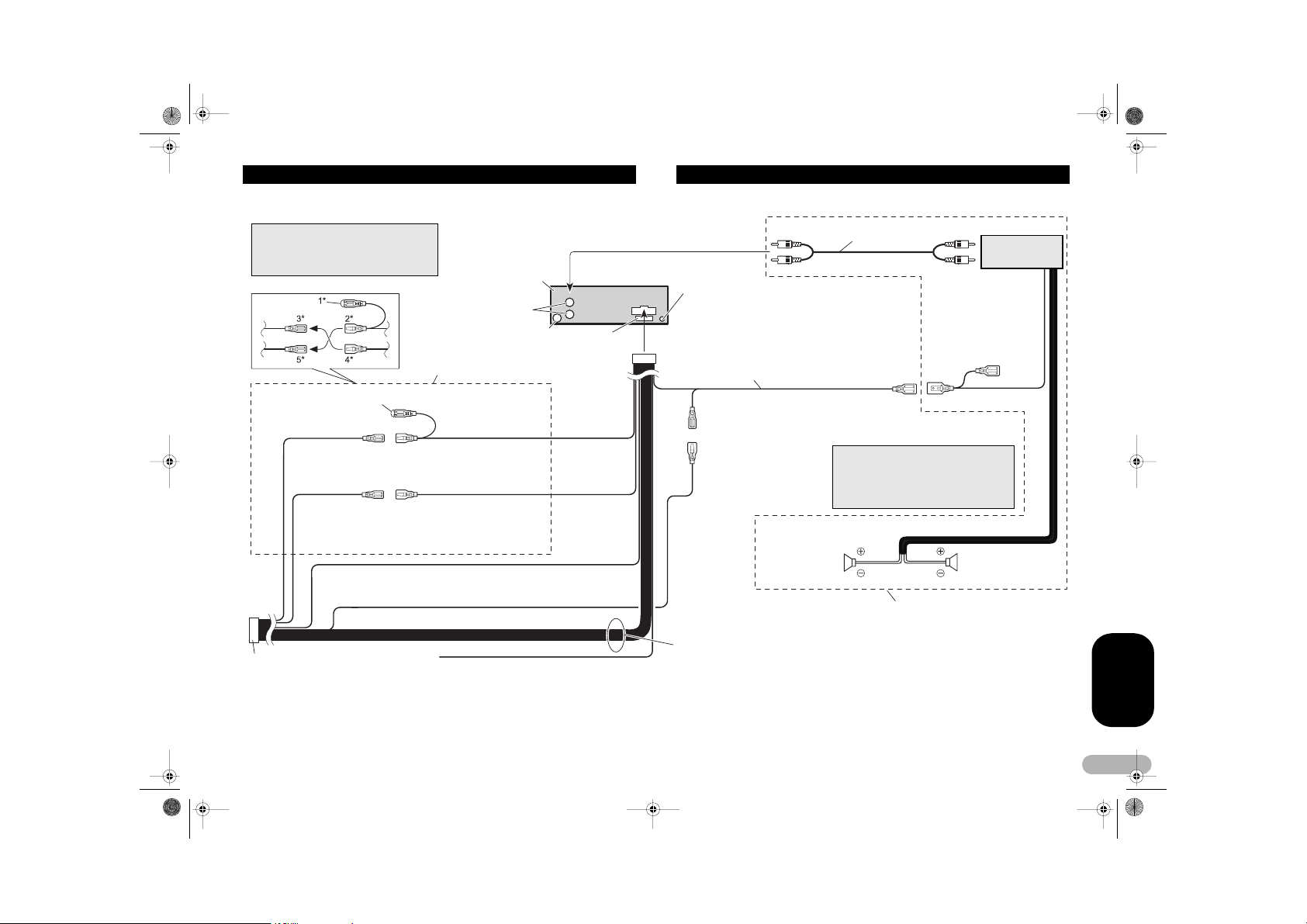
Connecting the Units
Note
Depending on the kind of vehicle, the
function of 3* and 5* may be di fferent. In this
case, be sure to connect 2* to 5* and 4* to 3*.
Cap (1*)
Do not remove cap if this
terminal is not in use.
Back-up (or accessory)
ISO connector
Note
In some vehicles, the ISO co nnector may
be divided into two. In thi s case, be sure
to connect to both conn ectors.
Yellow (3*)
Accessory (or back-
Yellow (2*)
Connect to the consta nt 12 V supply
terminal.
Red (4*)
Red (5*)
Connect to terminal co ntrolled by
ignition swich (12 V DC).
up)
Black (chassis grou nd)
Connect to a clean, paint- free metal location.
This product
Rear output
Antenna jack
Connect leads of the same
color to each other.
Yellow/bla ck
If you use an equipment wi th Mute
function, wire this lead to the Audio
Mute lead on that equ ipment. If not,
keep the Audio Mute l ead free of any
connections.
Fuse
(10 A)
Connect with RCA cables
(sold separately)
Wired remote input
Hard-wired remote control adaptor can
be connected (sold s eparately).
Blue/white
Connect to system control terminal of the
power amp (max. 300 mA 12 V DC).
Blue/white (7*)
Connect to auto-antenn a relay control
terminal (max. 300 mA 12 V DC).
Blue/white (6*)
Left Right
Rear Speaker Rear Speaker
Speaker leads
White: Front left +
White/black: Front left Gray: Front right +
Gray/black: Front right Green: Rear left +
Green/black: Rear left Violet: Rear right +
Violet/black: Rear right -
Power amp (sold
separately)
System remote contro l
The pin position of the I SO connector will
differ depends on the t ype of vehicle.
Connect 6* and 7* when P in 5 is an
antenna control type. In a nother type of
vehicle, never connect 6* and 7*.
Perform these connec tions when using
the optional amplifier.
ENGLISH
5
MAN-DEH-3900MP-GB.fm Page 6 Monday, January 15, 2007 3:45 PM
Before You Start
If you want to dispose this product, do not mix it with general household
waste. There is a separate collection system for used electronic
products in accordance with legislation that requires proper treatment,
recovery and recycling.
Private households in the 25 member states of the EU, in Switzerland and Norway
may return their used electronic products free of charge to designated collection
facilities or to a retailer (if you pur chase a similar new one) .
For countr ies not mentioned ab ove, please conta ct your local autho rities for the cor rect
method of disposal.
By doing so you will ensure that your disposed product undergoes the necessary
treatment, recovery and recycling and thus prevent potential negative effects on the
environment and human health.
About this unit
The tuner frequencies on this unit are allocated for use in Wes tern Europe , Asia, the
Middle East, Africa and Oceania. Use in other areas may result in poor rece ption. The
RDS (radio data system) function operates only in areas with FM stations broadcasting
RDS signals.
! CAUTION
• Do not allow this unit to come into contact with liquids. Electrical shock could result.
Also, this unit damage, smoke, and overheat could result from contact with liquids.
• “CLASS 1 LASER PRODUCT”
This product contains a laser diode of higher class than 1. To ensure continued
safety, do not remove any covers or attempt to gain access to the inside of the
product. Refer all servicing to qualified personnel.
• The Pioneer CarStereo-Pass is for use only in Germany.
• Keep this manual handy as a reference for operating procedures and precautions.
• Always keep th e volume low enough so that you can hear sounds from outside the
vehicle.
• Protect this unit from moisture.
• If the battery is disconnected or discharged, the preset memory will be erased and
must be reprogrammed.
• Should this product fail to operate properly, contact your dealer or nearest
authorized Pioneer Service Station.
About WMA
The Windows Media™ logo printed on the box indicates
that this unit can play back WMA data.
WMA is short for Windows Media Audio and refers to an
audio compression technology that is developed by
Microsoft Corporation. WMA data can be encoded by
using Windows Media Player version 7 or later.
Windows Media and the Windows logo are trademarks or registered trademarks of
Microsoft Co rporation in the United States and/or other countries.
Note
• This unit may not operate correctly depending on the a pplication used to encode WMA files.
About MP3
Supply of this product only conveys a license for private, non-commercial use and
does not convey a license nor imply any right to use this product in any commercial
(i.e. revenue-generating) real time broadcasting (terrestrial, satellite, cable and/or any
other media), broadcasting/streaming via internet, intranets and/or other networks or
in other electronic content distribution systems, such as pay-audio or audio-ondemand applications. An independent license for such use is required. For details,
please visit http://www.mp3licensing.com.
Visit our website
Visit us at the following site:
• Register your product. We will keep the details of your purchase on file to help you
refer to this information in the ev ent of an insurance claim such as loss or theft.
• We offer the latest informati on about Pioneer Corporation on our website.
6
ENGLISH
 Loading...