

Pioneer DEH-1701UB User manual

CD RDS RECEIVER
CD RDS ПРИЕМНИК
DEH-1701UB
English Русский
Owner’s Manual
Руководство пользователя

Table of Contents
About this manual:
• In the following instructions, a USB memory or USB audio player are referred to as
“USB device”.
Before You Start....................................................................................... 3
Getting Started........................................................................................ 3
Radio.......................................................................................................... 6
CD/USB/AUX............................................................................................. 6
Settings..................................................................................................... 7
FUNCTION settings ................................................................................. 8
AUDIO settings......................................................................................... 8
SYSTEM settings ...................................................................................... 9
ILLUMINATION settings.......................................................................... 9
Connections/Installation ..................................................................... 10
Additional Information ........................................................................ 12
2En
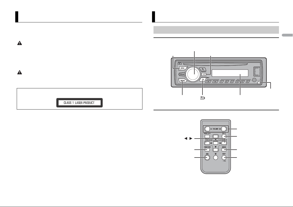
Before You Start
SRC (source)/OFF
Detach button
Display window
M.C. (multi-control) dial
BAND /DIMMER
Display button*
/
SRC (source)
VOLUME +/–
MUTE
DISP (display)
FUNCTION AUDIO
Thank you for purchasing this PIONEER product
To ensure proper use, please read through this manual before using this product. It is especially
important that you read and observe WARNI NGs and CAUTIONs in this manual. Please keep the
manual in a safe and accessible place for future reference.
WARNI NG
• Do not attempt to install or service this product by yourself. Installation or servicing of this
product by persons without training and experience in el ectronic equipment and automotive
accessories may be dangerous a nd could expose you t o the risk of elec tric shock, in jury or other
hazards.
• Do not attempt to operate the uni t while driving. Make sure to pull off the road and park your vehicle
in a safe location before attempting to use the controls on the device.
CAUTION
• Do not allow this unit to come into contact with moisture and/or liquids. Electrical shock could result.
Also, damage to this unit, smoke, and overheating could result from contact with liquids.
• Always keep the volume low enough to hear outside sounds.
CAUTION
This product is a class 1 laser product classified under the Safety of laser products, IEC 60825-1:2007.
Getting Started
Basic operation
English
DEH-1701UB
* This button is refer red to as DISP in the manual.
If you experience problems
Should this unit fail to work properly, please contact your dealer or nearest authorized PIONEER Service
Station.
Remote Control
3En
Frequently used operations
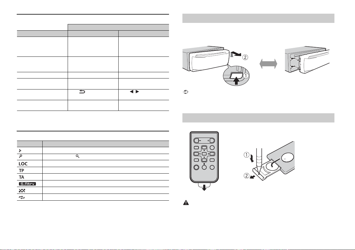
Detach Attach
How to replace the battery
Insert the CR2025 (3 V) battery with the plus (+) and
minus (–) poles orientated properly.
Operation
Purpose Head Unit Remote Control
Turn on the power* Press SRC/OFF to turn on
Adjust the volume Turn the M.C. dial. Press VOLUME + or –.
Select a source Press SRC/OFF repeatedly. Press SRC repeatedly.
Change the display
information
Return to th e previous
display/list
Return to the normal display
from the menu
* When this unit’s blue/wh ite lead is connected to the vehicl e’s auto-antenna relay control terminal,
the vehicle’s antenn a extends when this unit’s source is turned on. To retract the anten na, turn the
source off.
the power.
Press and hold SRC/OFF to
turn off the power.
Press DISP repeatedly. Press DISP repeatedly.
Press /DIMMER.Press / to select the
Press BAND.
Press SRC to turn on the
power.
Press and hold SRC to turn
off the power.
Press MUTE to mute the
unit. Press again to unmute.
next/previous folder.
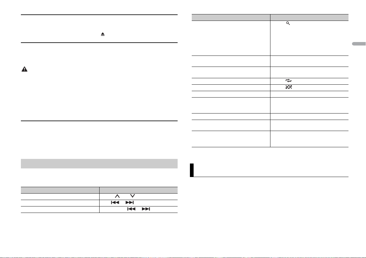
Display indication
Indication Description
Appears when a lower tier of the menu or folder exists.
Appears when the button is pressed.
Appears when the local seek tuning function is set (page 8).
Appears when a traffic program is received.
Appears when traffic announcements are received (page 8).
Appears when the sound retriever function is set (page 8).
Appears when random play is set.
Appears when repeat play is set.
Detaching the front panel
Detach the front panel to prevent theft. Remove any cables and devices attached to the
front panel and turn off the unit before detaching it.
Important
• Avoid subjecting the front panel to excessive shock.
–
• Keep the front panel out of direct sunlight and high temperatures.
• Always store the detached front panel in a protective case or bag.
Preparing the remote control
Remove the insulation sheet before use.
WARNING
• Keep the battery out of the reach of children. Should the battery be swallowed, consult a doctor
immediately.
• Do not expose the battery or remote control to excessive heat such as direct sunlight or fire.
4En
CAUTION
• There is a potential danger of explosion if the battery is incorrectly replaced. When replacing the
battery, replace it with the same type.
• Do not handle or store the battery with metallic tools or objects.
• If the battery leaks, remove the battery and wipe the remote control completely clean. Then install a
new batter y.
• When disposing of used batteries, compliance with governmental regulations or environmental
institution s’ rules that ap ply in your country/area must be followed that pertain to any s pecial
handling needed for disposal.
Important
• Do not store the remote control in high temperatures or direct sunlight.
• Do not let the remote control fall onto the floor, where it may become jammed under the brake or
accelerator pedal.
Setup menu
When you turn the ignition switch to ON after installation, [SET UP :YES] appears in the
display.
1 Press the M.C. dial.
The setup menu disappears after 30 seconds of no operation. If you prefer not to set
at this time, turn the M.C . dial to select [NO], then press to confirm.
2 Tur n the M.C. dial to select the options, then press to confirm.
To proceed to the next menu option, you need to confirm your selection.
Menu Item Description
LANGUAGE Select the language to display the text information from a
[ENG](English),
[РУС](Russian),
[TUR]( Turkish)
CLOCK SET Set the clock.
FM STEP Select the FM tuning step from 100 kHz or 50 kHz.
[100], [50]
compressed audio file.
3 [QUIT :YES] appears when all the settings have been made.
To return to the first item of the setup menu, turn the M.C. dial to select [QUIT :NO],
then press to confirm.
4 Press the M.C. dial to confirm the settings.
NOTES
• You can cancel the menu setting by pressing SRC/OFF.
• These settings can be made at any time from the SYSTEM settings (page9) and INITIAL settings
(page 5).
Canceling the demonstration display (DEMO OFF)
1 Press the M.C. dial to display the main menu.
2 Tur n the M.C. dial to select [SYSTEM], then press to confirm.
3 Tur n the M.C. dial to select [DEMO OFF], then press to confirm.
4 Tur n the M.C. dial to select [YES], then press to confirm.
INITIAL settings
1 Press and hold SRC/OFF until the unit turns off.
2 Press and hold SRC/OFF to display the main menu.
3 Tur n the M.C. dial to select [INITIAL], then press to confirm.
4 Tur n the M.C. dial to select an option, then press to confirm.
Menu Item Description
FM STEP Select the FM tuning step from 100 kHz or 50 kHz.
[100], [50]
SP-P/O MODE Select when there is a full-range speaker connected to the rear
[REAR/SUB.W]
[SUB.W/SUB.W] Select when there is a passive subwoofer connected directly to
[REAR/REAR] Select when there are full-range speakers connected to the rear
SYSTEM RESET Select [YES] to initialize the unit settings. The unit will be
[YES], [CANCEL]
speaker output leads and there is a subwoofer connected to the
RCA output.
the rear speaker output leads and there is a subwoofer
connected to the RCA output.
speaker output leads and RCA output. If there is a full-range
speaker connected to the rear speaker output leads, and the
RCA output is not used, you may select either [REAR/SUB.W] or
[REAR/REAR].
restarted automatically.
(Some of the settings may be retained even after resetting the
unit.)
English
5En
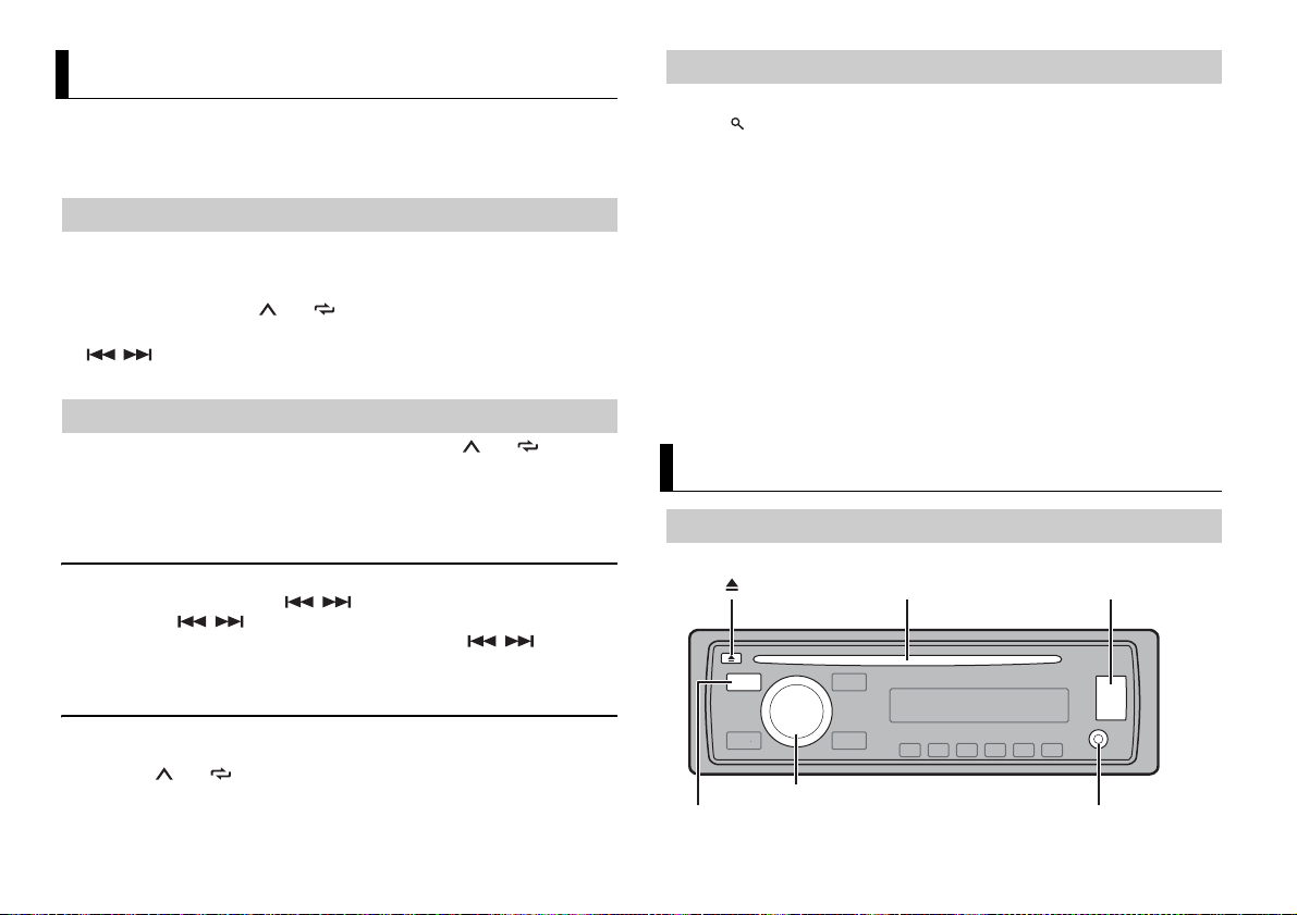
Radio
AUX input jack (3.5 mm stereo jack)
(eject)
Disc loading slot USB port
SRC (source)/OFF
M.C. (multi-control) dial
The tuner frequencies on this unit are allocated for use in Western Europe, Asia, the
Middle East, Africa and Oceania. Use in other areas may result in poor reception. The RDS
(radio data system) function only works in areas that broadcast RDS signals for FM
stations.
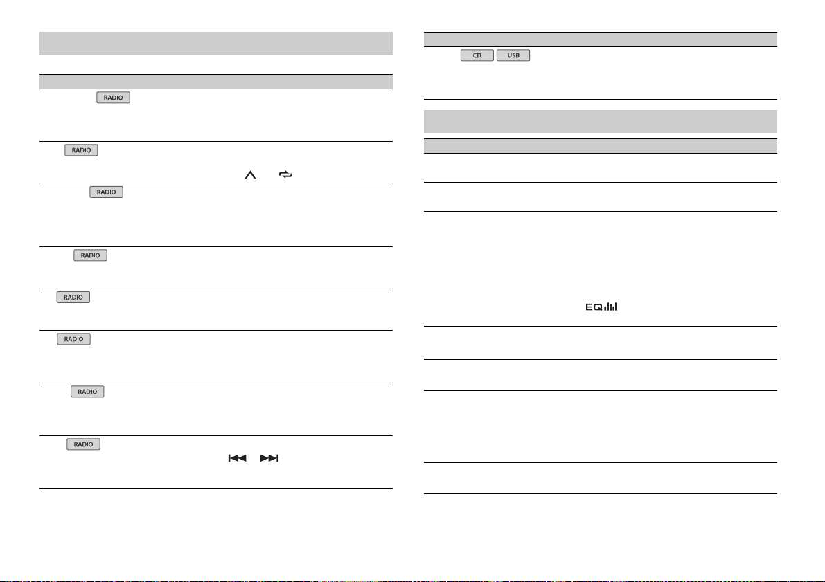
Receiving preset stations
1 Press SRC/OFF to select [RADIO].
2 Press BAND to select the band from [FM1], [FM2], [FM3], [MW] or [LW].
3 Press a number button (1/ to 6/).
TIP
The / buttons can be also used to select a preset station when [SEEK] is set to [PCH] in the
FUNCTION settings (p age 8).
Best stations memory (BSM)
The six strongest stations are stored on the number buttons (1/ to 6/).
1 After selecting the band, press the M.C. dial to display the main menu.
2 Turn the M.C. dial to select [FUNCTION], then press to confirm.
3 Turn the M.C. dial to select [BSM], then press to confirm.
To seek a station manually
1
After selecting the band, press / to select a station.
Press and hold / then release to seek an available station. Scanning stops
when the unit receives a station. To cancel seek tuning, press / .
NOTE
[SEEK] needs to be set to [MAN] in the FUNCTION settings (page 8).
Using PTY functions
The unit searches for a station by PTY (program type) information.
1 Press during FM reception.
2 Tur n th e M.C. dial to select a program type from [NEWS/INFO], [POPULAR],
[CLASSICS] or [OTHERS].
3 Press the M.C. dial.
The unit begins to search for a station. When it is found, its program service name is
displayed.
NOTES
• To cancel the search, press the M.C. dial.
• The program of some stations may differ from that indicated by the transmitted PTY.
• If no station is broadcasting the type of program you searched for, [NOT FOUND] is displayed for
about two seconds and then the tuner returns to the original station.
PTY list
For more details about PTY list, visit the following site:
http://www.pioneer.eu/eur/products/25/121/tech/CarAudio/PTY.html
CD/USB/AUX
Playing back
Disconnect headphones from the device before connecting it to the unit.
To store stations manually
1
While receiving the station you want to store, press and hold one of the number
buttons (1/ to 6/ ) until it stops flashing.
6En
CD
1
Insert a disc into the disc loading slot with the label side u p.
To eject a disc, stop playback first then press .
USB device
1 Open the USB port cover.
2 Plug in the USB device using an appropriate cable.
CAUTION
Use an optional Pioneer USB cable (CD-U50E) to connect the USB device as any device connected
directly to the unit will protrude out from the unit, which could be dangerous.
Before removing the device, stop playback.
MTP connection
A device installed with Android OS 4.0 or later can be connected to the unit via MTP, using the cable
supplied with the device. However, depending on the connected device and the numbers of the files in
the device, audio files/songs may not be able to be played back via MTP. Note that MTP connection is
not compat ible with WAV and FLAC file for mats.
AUX
1
Insert the stereo mini plug into the AUX input jack.
2 Press SRC /OFF to select [AUX] as the source.
NOTE
If [AUX] is set to [OFF] in the SYSTEM se ttings, [AUX] cannot be selected as a source (page 9).
Operations
You can make various adjustments in the FUNCTION settings (page 8).
Note that the following operations do not work for an AUX device. To operate an AUX
device, use the device itself.
Purpose Operation
Select a folder/album* Press 1/ or 2/.
Select a track/song (chapter) Press or .
Fast forward or reverse Press and hold or .
Purpose Operation
Search for a file from a list 1 Press to display the list.
View a list of the files in the selected folder/
category*
Play a song in the selected folder/category* Press and hold the M.C. dial when a folder/
Repeat play Press 6/.
Random play Press 5/.
Pause/resume playback Press 4/PAU SE.
Sound retriever Press 3/S.Rtrv.
Return to root folder (USB only)* Press and hold BAND.
Switch between compressed audio and CD-
DA (CD only)
Change drives in USB device
(Devices that support the USB mass storage
device class protocol only)
* Compressed audio files only
2 Turn t he M.C. dial to select the desired
file (folder) name or category, then press
to confirm.
3 Turn t he M.C. dial to select the desired
file, then press to confirm.
Playback starts.
Press the M.C. dial when a folder/category
is selected.
category is selected.
[1]: Effective for low compression rates
[2]: Effective for high compression rates
Press BAN D.
Press BAN D.
Settings
You can adjust various settings in the main menu.
1 Press the M.C. dial to display the main menu.
2 Tur n the M.C. dial to select one of the categories below, then press to confirm.
• FUNCTION settings (page 8)
• AU DIO settings (page 8)
• SYSTEM settings (page 9)
• ILLUMINATION settings (page 9)
3 Tur n the M.C. dial to select the options, then press to confirm.
English
7En
FUNCTION settings
USB
The menu items vary according to the source.
Menu Item Description
FM SETTING
[TALK], [STANDARD], [MUSIC] Match the sound quality level with the broadcast
BSM
REGIONAL
[ON], [OFF] Limit the reception to the specific regional
LOC AL
FM: [OFF], [LV1], [LV2], [LV3], [LV4]
MW/LW: [OFF], [LV1], [LV2]
TA
[ON], [OFF] Receive current traffic information if available.
AF
[ON], [OFF] Allow the unit to retune to a different frequency
NEWS
[ON], [OFF] Interrupt the currently selected source with
SEEK
[MAN], [PCH] Assign or buttons to seek the stations
signal conditions of the FM band signal.
(Available only when FM band is selected.)
Store the six strongest stations on the number
buttons (1/ to 6/ ) automatically.
programs when AF (alternative frequencies
search) is selected. (Available only when FM
band is selected.)
Restrict the tuning station according to the
signal strength.
(Available only when FM band is selected.)
providing the same station. (Available only when
FM band is selected.)
news programs. (Available only when FM band is
selected.)
one by one (manual tuning) or select a station
from the preset channels.
Menu Item Description
S.RTRV
[1] (effective for low compression
rates), [2] (effective for high
compression rates), [OFF]
Enhance compressed audio and restore rich
sound. (Not available when the FLAC file is
played back.)
AUDIO settings
Menu Item Description
FAD ER *1
Adjust the front and rear speaker balance.
BALANCE
Adjust the left and right speaker balance.
EQ SETTING
[SUPER BASS], [POWERFUL],
[NATURAL], [VOCAL], [CUSTOM1],
[CUSTOM2], [FLAT]
Select an equalizer band and
level for further customizing.
Equalizer band: [80HZ], [250HZ],
[800HZ], [2.5KHZ], [8KHZ]
Equalizer le vel: [+6] to [– 6]
LOU DNES S
[OFF], [LOW], [MID], [HI] Compensate for clear sound at low volume.
SUB.W*2
[NOR], [REV], [OFF] Select the subwoofer phase.
SUB.W CTRL*2*3
Cut-off frequency: [50HZ],
[63HZ], [80HZ], [100HZ], [125HZ],
[160HZ], [200HZ]
Output level: [–24] to [+6]
Slope level: [–12], [–24]
BASS BOOST
[0] to [+6] Select the bass boost level.
Select or customize the equalizer curve.
[CUSTOM1] can be set separately for each source.
However, each of the below combinations are set
to the same setting automatically.
[CUSTOM2] is a shared setting used for all
sources.
You can also switch the equalizer by pressing
repeatedly.
Only frequencies lower than those in the
selected range are output from the subwoofer.
8En
Menu Item Description
HPF SETTING
Cut- off fre quenc y: [OFF], [50HZ],
[63HZ], [80HZ], [100HZ], [125HZ],
[160HZ], [200HZ]
Slope level: [–12], [–24]
SLA
[+4] to [–4] Adjust the volume level for each source except
*1 Not availabl e when [SUB.W/SUB.W] is selected in [SP-P/O MODE] in the INITIAL settings (page 5).
*2 Not available when [R EAR/REAR] is selected in [SP-P/O MODE ] in the INITIAL settings (page 5).
*3 Not available when [OFF] is selected in [SUB.W].
Only frequencies higher than the high-pass filter
(HPF) cutoff are output from the speakers.
FM.
SYSTEM settings
You can also access to these menus when the unit is turned off.
Menu Item Description
LANGUAGE
[ENG](English), [РУС](Russian),
[TUR]( Turkish)
CLOCK SET
12H/24H
[12H], [24H] Select the time notation.
AUTO P I
[ON], [OFF] Search for a different station with the same
AUX
[ON], [OFF] Set to [ON] when using an auxiliary device
MUTE MODE
[MUTE], [20dB ATT], [10dB ATT] Mute or attenuate sound automatically when a
Select the language to display the text
information from a compressed audio file.
Set the clock (page 5).
programming, even if using a preset station.
connected to the unit.
signal from equipment with a mute function is
received.
Menu Item Description
PW SAVE*
[ON], [OFF] Reduce the battery power consumption.
* [PW SAVE] is canceled if the vehicle battery is disconnected and will need to be turned back on once
the battery is reconnected. When [PW SAVE] is off, depending on connection methods, the unit may
continue to draw power from the battery if your vehicle’s ignition does not have an ACC (accessory)
position.
Turning on the source is the only operation
allowed when this function is on.
ILLUMINATION settings
Menu Item Description
DIM SETTING
[SYNC CLOCK], [MANUAL] Change the display brightness.
BRIGHTNESS
[1] to [10] Change the display brightness.
The available setting ranges differ depending on
[DIM SETTING].
English
9En
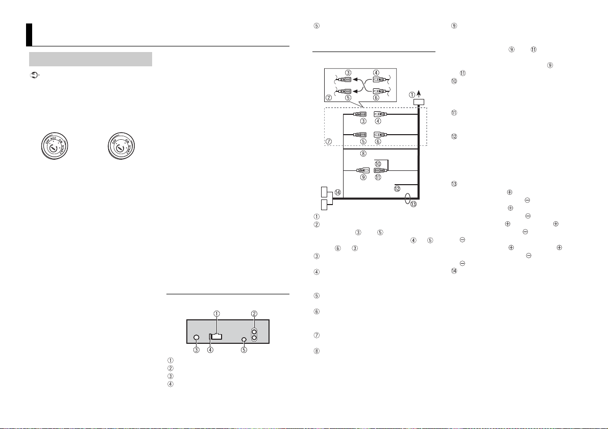
Connections/Installation
ACC position No ACC positio n
Connections
Important
• When installing this unit in a vehicle
without an ACC (accessory) position on
the ignition switch, failure to connect the
red cable to the terminal that detects
operation of the ignition key may result
in battery drain.
• Use of this unit in conditions other than
the following could result in fire or
malfunction.
– Vehicles with a 12-volt battery and
negative grounding.
– Speakers with 50 W (output value) and
4 Ω to 8 Ω (impedance value).
• To prevent a short-circuit, overheating or
malfunction, be sure to follow the
directions below.
– Disconnect the negative terminal of the
battery before installation.
– Secure the wiring with cable clamps or
adhesive tape. Wrap adhesive tape
around wiring that comes into contact
with metal parts to protect the wiring.
– Place all cables away from moving parts,
such as the shift lever and seat rails.
– Place all cables away from hot places,
such as near the heater outlet.
– Do not connect the yellow cable to the
battery by passing it through the hole
to the engine compartment.
– Cover any disconnected cable
connectors with insulating tape.
–Do not shorten any cables.
– Never cut the insulation of the power
cable of this unit in order to share the
power with other devices. The current
capacity of the cable is limited.
– Use a fuse of the rating prescribed.
– Never wire the negative speaker cable
directly to ground.
– Never band together negative cables of
multiple speakers.
• When this unit is on, control signals are
sent through the blue/white cable.
Connect this cable to the system remote
control of an external power amp or the
vehicle’s auto-antenna relay control
terminal (max. 300mA 12 V DC). If the
vehicle is equipped with a glass antenna,
connect it to the antenna booster power
supply terminal.
• Never connect the blue/white cable to
the power terminal of an external power
amp. Also, never connect it to the power
terminal of the auto antenna. Doing so
may result in battery drain or a
malfunc tion.
• The black cable is ground. Ground cables
for this unit and other equipment
(especially, high-current products such as
power amps) must be wired separately. If
they are not, an accidental detachment
may result in a fire or malfunction.
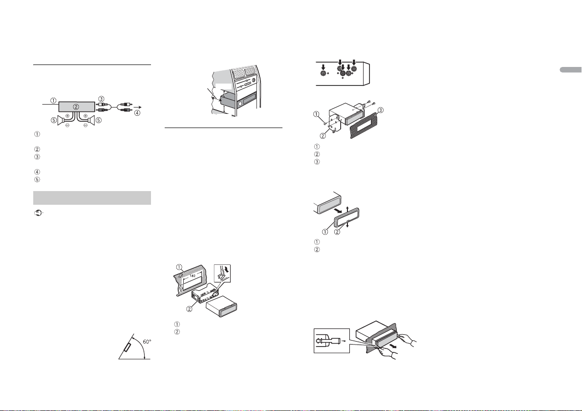
This unit
Power cord input
Rear output or subwoofer output
Antenna input
Fuse (10 A)
Wired remote input
Hard-wired remote control a dapter can
be connected (sold separately).
Power cord
To power cord input
Depending on the kind of vehicle, the
function of and may be different.
In this case, be sure to connect to
and to .
Yel l ow
Back-up (or accessory)
Yel l ow
Connect to the constant 12 V supply
terminal.
Red
Accessory (or back-up)
Red
Connect to terminal controlled by the
ignition switch (12 V DC).
Connect leads of the same color to each
other.
Black (chassis ground)
Blue/white
The pin position of the ISO connector
will differ depending on the type of
vehicle. Connect and when Pin 5
is an antenna control type. In another
type of vehicle, never connec t and
.
Blue/white
Connect to the system control terminal
of the power amp (max. 300 mA 12 V
DC).
Blue/white
Connect to the auto-antenna relay
control terminal (max. 300 mA 12 V DC).
Yel l ow /b la ck
If you use equipment with a Mute
function, wire this lead to the Audio
Mute lead on that equipment. If not,
keep the Audio Mute lead free of any
connections.
Speaker leads
White: Front left
White/black: Front left
Gray: Front right
Gray/black: Front right
Green: Rear left or subwoofer
Green/black: Rear left or subwoofer
Violet: Rear right or subwoofer
Violet/b lack: Rear r ight or subwoo fer
ISO connector
In some vehicles, the ISO connector
may be divided into two. In this case, be
sure to connect to both connectors.
NOTES
• Chan ge the initial menu of this unit. Refer
to [SP-P/O MODE] (page 5). The
subwoofer output of this unit is
monaural.
10En
• When using a subwoofer of 70 W (2 Ω), be
Leave ample
space
5 cm
5 cm
sure to connect the subwoofer to the
violet and violet/black leads of this unit.
Do not connect anything to the green
and green/black leads.
Power amp (sold separately)
Perform these connections when us ing the
optional amplifier.
• When installing, to ensure proper heat
dispersal when using this unit, make sure
you leave ample space behind the rear
panel and wrap any loose cables so they
are not blocking the vents.
DIN Rear-mount
1 Determine the appropriate position
where the holes on the bracket and
the side of the unit match.
2 Tighten two screws on each side.
English
System remote control
Connect to blue/white cable.
Power amp (sold separately)
Connect with RCA cables (sold
separately)
To rear output or subwoofer output
Rear speaker or subwoofer
Installation
Important
• Chec k all connections and systems before
final installation.
• Do not use unauthorized parts as this
may cause malfunctions.
• Consult your dealer if installation requires
drilling of holes or other modifications to
the vehicle.
• Do not install this unit where:
– it may interfere with operation of the
vehicle.
– it may cause injury to a passenger as a
result of a sudden stop.
• The sem iconductor laser will be damaged
if it overheats. Install this unit away from
hot places such as near the heater outlet.
• Optimum performance is
obtained when the unit is
installed at an angle of less
than 60°.
DIN front/rear mount
This unit can be properly installed using
either front-mount or rear-mount
installation.
Use commercially available parts when
installing.
DIN Front-mount
1 Insert the mounting sleeve into the
dashboard.
For installation in shallow spaces, use
the supplied mounting sleeve. If there is
enough space, use the mounting sleeve
that came with the vehicle.
2 Secure the mounting sleeve by using a
screwdriver to bend the metal tabs
(90°) into place.
Dashboard
Mounting sleeve
• Make sure that the unit is installed
securely in place. An unstable
installation may cause skipping or
other malfunctions.
Tapping screw (5 mm × 8 mm)
Mounting bracket
Dashboard or console
Removing the unit
1 Remove the trim ring.
Trim r ing
Notched tab
• Rele asing the front panel allows easier
access to the tr im ring.
• When reattaching the trim ring, point
the side with the notched tab down.
2 Insert the supplied extraction keys
into both sides of the unit until they
click into place.
3 Pull the unit out of the dashboard.
11En
 Loading...