

Page 1
DJ Controller
http://pioneerdj.com/support/
The Pioneer website shown above offers FAQs, information on software and various other types of information
and services to allow you to use your product in greater comfort.
Operating Instructions
Page 2

Contents
How to read this manual
! In this manual, names of screens and menus displayed on the
computer screen, as well as names of buttons and terminals on
the product, etc., are indicated within brackets. (e.g.: [RECORD]
panel, [Preferences] menu, [CUE] button, [VINYL] mode, [AUX IN]
terminals)
! Explanations of TRAKTOR PRO 2 functions are indicated
TRAKTOR PRO 2
Before start
Features ....................................................................................................... 3
System setup example ............................................................................... 3
What’s in the box ........................................................................................ 4
Using the LAPTOP DOCK .......................................................................... 4
Using with the feet removed ...................................................................... 4
Before you start
About the driver software (Windows) ....................................................... 5
About the TRAKTOR LE 2 software ........................................................... 7
Launching TRAKTOR 2 .............................................................................. 8
Performing product activation .................................................................. 8
Updating the TRAKTOR 2 software ......................................................... 10
Initial settings ............................................................................................ 10
Connections
Names of terminals .................................................................................. 12
Connecting the input/output terminals .................................................. 13
.
Part names and functions
Control panel ............................................................................................. 14
1 Browser ................................................................................................... 15
2 Deck ........................................................................................................ 15
3 Mixer ....................................................................................................... 17
4 Effect ....................................................................................................... 18
5 Loop recorder ......................................................................................... 18
Basic Operation
Starting the system ................................................................................... 19
Loading tracks and playing them ............................................................ 19
Outputting sound ..................................................................................... 19
Mixing ........................................................................................................ 19
Inputting the sound of an external device or microphone .................... 20
Quitting the system .................................................................................. 20
Advanced Operation
Using the CUE function ............................................................................ 21
Using the LOOP function ......................................................................... 21
Using the EFFECT function ...................................................................... 21
Switching the jog dials’ illumination mode ............................................ 21
List of MIDI Messages
1 Browser ................................................................................................... 22
2 Deck ........................................................................................................ 23
3 Mixer ....................................................................................................... 26
4 Effect ....................................................................................................... 27
5 Loop recorder ......................................................................................... 29
Additional information
Troubleshooting ........................................................................................ 30
Using as a controller for other DJ software ............................................ 31
About trademarks and registered trademarks ...................................... 31
Cautions on copyrights ............................................................................ 31
Specifications............................................................................................ 31
En
2
Page 3
Before start
Features
This unit, while using the same operation panel layout as Pioneer’s professional DJ equipment, has a rounded, amiable form. It is designed to
allow a wide range of users – from those at the start of their DJing experience to those who have already begun DJ performances in their home
and elsewhere – to enjoy DJ performances in a variety of situations.
PULSE CONTROL
Thanks to the use of the newly developed “Pure Platter” jog dials with
four white LEDs and channel faders with built-in LEDs, the illumination
changes in conjunction with DJ operations, effects, etc., adding brilliance to DJ performances.
! Mix Pulse: The offset of the tempo on the two decks is expressed by
the white illumination of the jog dials. The white illumination is lit
brightly when the tempos on the two decks are synchronized, and
the more the tempos are apart, the dimmer the white illumination.
! Beat Pulse: The illumination of the channel faders flashes according
to the decks’ audio levels.
! Launch Pulse: The deck’s illumination changes when a track is
loaded.
! FX Pulse: The jog dial’s illumination changes in response to effect
operations.
TRAKTOR PRO 2
Before start
LAPTOP DOCK
This unit uses a new “Laptop Dock” structure by which, when installed
at an angle, the keyboard section of a notebook computer slides under
the controller.
Not only can the controller be installed in small spaces, it can be set at
an angle with the feet still on and operated while seated in a chair, or the
feet can be removed and the controller operated while standing, allowing users to enjoy a wide range of DJ performance styles.
TRAKTOR LE 2
The “TRAKTOR LE 2” DJ software offering a full range of basic functions
for DJ performances is included.
Also, upgrading to TRAKTOR PRO 2 makes it possible not only to operate a multitude of functions but also to control various other DJ software
programs.
USB BUS POWER
This product supports USB bus power. It can be used simply by connecting it to a computer with a USB cable.
DESIGN
This unit is designed with a rounded body, making it suitable to a wide
variety of lifestyles and harmonizing with all types of interiors.
In addition, the basically black design not only harmonizes with interiors
HIGH SOUND QUALITY
This product inherits the sound quality technology developed over the
years for Pioneer DJ hardware to achieve the top level of sound quality
in its class.
but also gives it a professional look.
Furthermore, the buttons and controls on the operation panel have the
same layout as Pioneer’s professional DJ devices.
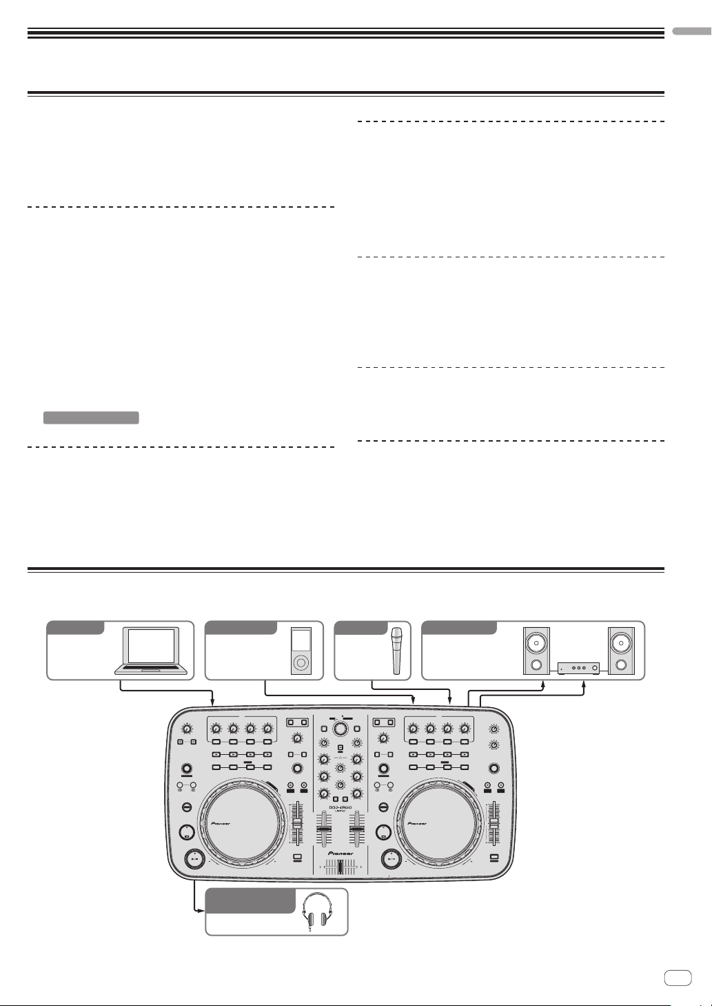
System setup example
A DJ system like the one on the diagram below can be created by combining this unit with a computer and peripherals.
DJ software
Computer
MINMAX
F2 F3
AUTO LOOP
MOVE GRID
IN OUT
SHIFT
CUE
F1
For audio input
Portable audio
device
FX1
CONTROL
MINMAX1MINMAX2MINMAX3MINMAX
123
ON
SAMPLER
DELETE
HOT CUE /
1234
REV
For audio input
Microphone
PUSH
BROWSE VIEW
TREE FLD OPEN
DECK
CA
LOAD
FILTER
GAIN
LPF HPF
1
SAMPLE VOL
VINYL KEYLOCK
S
E
A
R
C
H
PULSE
MODE
TEMPO
0
FWD
FUNCTION
MINMAX
FX
HI
REC
2
MIX
MINMAX
MID
CUE MASTE
VOL
MINMAX
LOW
TEMPO
CUE MASTE
PANGE
CUE
MINMAX
DJ CONTROLLER
10
9
8
7
6
5
4
3
2
1
0
SYNC
MASTER
MINMAX
MINMAX
MINMAX
MINMAX
DECK
BD
LOAD
FILTER
GAIN
LPF HPF
FX
HI
12
AUTO LOOP
MID
MOVE GRID
IN
LOW
SHIFT
10
9
8
7
6
5
4
CUE
3
2
1
0
For audio output
CONTROL
MINMAX1MINMAX2MINMAX3MINMAX
ON
1234
OUT
REV
Component, amplifier,
powered speaker, etc.
FX2
123
SAMPLER
DELETE
HOT CUE /
MASTER VOL
MINMAX
AUX / MIC VOL
MINMAX
SAMPLE VOL
VINYL KEYLOCK
S
E
A
R
C
H
PULSE
TEMPO
MODE
PANGE
TEMPO
0
SYNC
MASTER
FWD
For checking
the audio input/output
Headphones
En
3
Page 4
What’s in the box
! TRAKTOR LE 2 software CD-ROM
! Driver software/operating instructions CD-ROM
! USB cable
! Read Before Use (Important)
! Quick Start Guide
! Service Center Guide (for Japanese customers)
! Warranty card
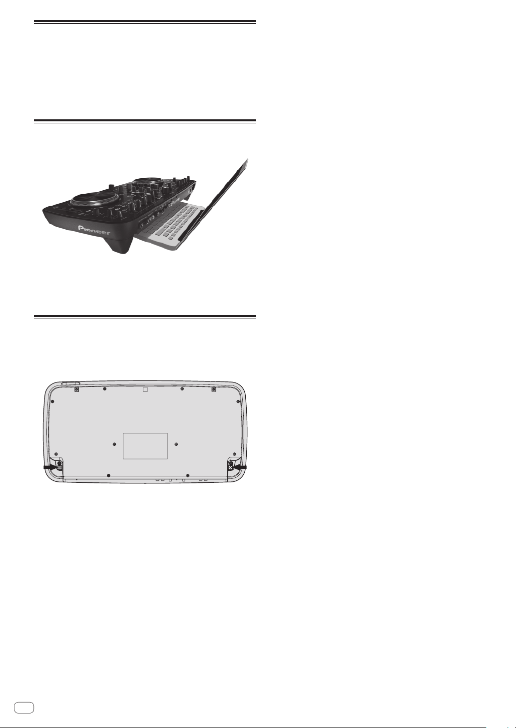
Using the LAPTOP DOCK
The computer’s keyboard section can be stowed under this unit.
! Depending on the size of your (notebook) computer, the keyboard
section may not fit in the LAPTOP DOCK.
! Install in such a way that the computer unit does not touch this unit.
! Install in such a way that the cables connected to the computer are
not stuck under this unit.
Using with the feet removed
This unit’s two feet can be removed.
Use a Phillips screwdriver to remove the screws from the
left and right feet.
! The screws you have removed will be needed when mounting
the feet. Be careful not to lose them. The feet cannot be properly
mounted using other screws.
En
4
Page 5

Before you start
Before you start
About the driver software (Windows)
This driver software is an exclusive ASIO driver for outputting audio
signals from the computer.
! There is no need to install the driver software when using Mac OS X.
Software end user license agreement
This Software End User License Agreement (“Agreement”) is between
you (both the individual installing the Program and any single legal
entity for which the individual is acting) (“You” or “Your”) and PIONEER
CORPORATION (“Pioneer”).
TAKING ANY STEP TO SET UP OR INSTALL THE PROGRAM MEANS
THAT YOU ACCEPT ALL OF THE TERMS OF THIS LICENSE AGREEMENT.
PERMISSION TO DOWNLOAD AND/OR USE THE PROGRAM IS
EXPRESSLY CONDITIONED ON YOUR FOLLOWING THESE TERMS.
WRITTEN OR ELECTRONIC APPROVAL IS NOT REQUIRED TO MAKE
THIS AGREEMENT VALID AND ENFORCEABLE. IF YOU DO NOT
AGREE TO ALL OF THE TERMS OF THIS AGREEMENT, YOU ARE NOT
AUTHORIZED TO USE THE PROGRAM AND MUST STOP INSTALLING IT
OR UNINSTALL IT, AS APPLICABLE.
1 DEFINITIONS
1 “Documentation” means written documentation, specifications
and help content made generally available by Pioneer to aid in
installing and using the Program.
2 “Program” means all or any part of Pioneer’s software licensed to
You by Pioneer under this Agreement.
2 PROGRAM LICENSE
1 Limited License. Subject to this Agreement’s restrictions,
Pioneer grants to You a limited, non-exclusive, non-transferable,
license (without the right to sublicense):
a To install a single copy of the Program in Your computer or
mobile device, to use the Program only for Your personal purpose complying with this Agreement and the Documentation
(“Authorized Use”);
b To use the Documentation in support of Your Authorized Use;
and
c To make one copy of the Program solely for backup pur-
poses, provided that all titles and trademark, copyright and
restricted rights notices are reproduced on the copy.
2 Restrictions. You will not copy or use the Program or
Documentation except as expressly permitted by this Agreement.
You will not transfer, sublicense, rent, lease or lend the Program,
or use it for third-party training, commercial time-sharing or
service bureau use. You will not Yourself or through any third
party modify, reverse engineer, disassemble or decompile the
Program, except to the extent expressly permitted by applicable
law, and then only after You have notified Pioneer in writing of
Your intended activities.
3 Ownership. Pioneer or its licensor retains all right, title and
interest in and to all patent, copyright, trademark, trade secret
and other intellectual property rights in the Program and
Documentation, and any derivative works thereof. You do not
acquire any other rights, express or implied, beyond the limited
license set forth in this Agreement.
4 No Support. Pioneer has no obligation to provide support,
maintenance, upgrades, modifications or new releases for the
Program or Documentation under this Agreement.
3 WARRANTY DISCLAIMER
THE PROGRAM AND DOCUMENTATION ARE PROVIDED “AS IS”
WITHOUT ANY REPRESENTATIONS OR WARRANTIES, AND YOU
AGREE TO USE THEM AT YOUR SOLE RISK. TO THE FULLEST EXTENT
PERMISSIBLE BY LAW, PIONEER EXPRESSLY DISCLAIMS ALL
WARRANTIES OF ANY KIND WITH RESPECT TO THE PROGRAM AND
DOCUMENTATION, WHETHER EXPRESS, IMPLIED, STATUTORY,
OR ARISING OUT OF COURSE OF PERFORMANCE, COURSE OF
DEALING OR USAGE OF TRADE, INCLUDING ANY WARRANTIES
OF MERCHANTABILITY, FITNESS FOR A PARTICULAR PURPOSE,
SATISFACTORY QUALITY, ACCURACY, TITLE OR NON-INFRINGEMENT.
4 DAMAGES AND REMEDIES FOR BREACH
You agree that any breach of this Agreement’s restrictions would cause
Pioneer irreparable harm for which money damages alone would be
inadequate. In addition to damages and any other remedies to which
Pioneer may be entitled, You agree that Pioneer may seek injunctive
relief to prevent the actual, threatened or continued breach of this
Agreement.
5 TERMINATION
Pioneer may terminate this Agreement at any time upon Your breach
of any provision. If this Agreement is terminated, You will stop using
the Program, permanently delete it from your computer or mobile
device where it resides, and destroy all copies of the Program and
Documentation in Your possession, confirming to Pioneer in writing
that You have done so. Sections 2.2, 2.3, 2.4, 3, 4, 5 and 6 will continue in
effect after this Agreement’s termination.
6 GENERAL TERMS
1 Limitation of Liability. In no event will Pioneer or its subsidiaries
be liable in connection with this Agreement or its subject matter,
under any theory of liability, for any indirect, incidental, special,
consequential or punitive damages, or damages for lost profits,
revenue, business, savings, data, use, or cost of substitute procurement, even if advised of the possibility of such damages or if
such damages are foreseeable. In no event will Pioneer’s liability
for all damages exceed the amounts actually paid by You to
Pioneer or its subsidiaries for the Program. The parties acknowledge that the liability limits and risk allocation in this Agreement
are reflected in the Program price and are essential elements of
the bargain between the parties, without which Pioneer would
not have provided the Program or entered into this Agreement.
2 The limitations or exclusions of warranties and liability contained
in this Agreement do not affect or prejudice Your statutory rights
as consumer and shall apply to You only to the extent such limitations or exclusions are permitted under the laws of the jurisdiction where You are located.
3 Severability and Waiver. If any provision of this Agreement is held
to be illegal, invalid or otherwise unenforceable, that provision
will be enforced to the extent possible or, if incapable of enforcement, deemed to be severed and deleted from this Agreement,
and the remainder will continue in full force and effect. The
waiver by either party of any default or breach of this Agreement
will not waive any other or subsequent default or breach.
4 No Assignment. You may not assign, sell, transfer, delegate or
otherwise dispose of this Agreement or any rights or obligations
under it, whether voluntarily or involuntarily, by operation of law
or otherwise, without Pioneer’s prior written consent. Any purported assignment, transfer or delegation by You will be null and
void. Subject to the foregoing, this Agreement will be binding
upon and will inure to the benefit of the parties and their respective successors and assigns.
5 Entire Agreement. This Agreement constitutes the entire agree-
ment between the parties and supersedes all prior or contemporaneous agreements or representations, whether written or
oral, concerning its subject matter. This Agreement may not be
modified or amended without Pioneer’s prior and express written
consent, and no other act, document, usage or custom will be
deemed to amend or modify this Agreement.
6 You agree that this Agreement shall be governed and construed
by and under the laws of Japan.
En
5
Page 6
Installing the driver software
! There is no need to install the driver software when using Mac OS X.
Operating environment
Supported operating systems
Windows® 7 Home Premium/Professional/
Ultimate
Windows Vista® Home Basic/
Home Premium/Business/Ultimate
Windows® XP Home Edition/Professional
(SP2 or later)
1 When using a 64-bit version of Windows, the driver software can only be used for
32-bit applications.
2 Windows 7 or greater is required to use in combination with TRAKTOR 2.
Before installing the driver software
! Read Software end user license agreement carefully.
! Turn off this unit’s power switch, then disconnect the USB cable
connecting this unit and the computer.
! If any other programs are running on the computer, quit them.
! To install or uninstall the driver software, you need to be authorized
by the administrator of your computer. Log on as the administrator of
your computer before proceeding with the installation.
! If you connect this unit to your computer without installing the driver
software first, an error may occur on your computer depending on
the system environment.
! If installation of the driver software is interrupted after it has started,
start the installation procedure over again from the beginning.
1 Turn on the computer’s power.
2 Insert the included driver software CD-ROM into the
computer’s CD drive.
3 Once the CD-ROM’s menu is displayed, double-click
[Pioneer_DDJ_Driver_XXXXX.exe].
4 Proceed with installation according to the instructions
on the screen.
If [Windows Security] appears on the screen while the installation is
in progress, click [Install this driver software anyway] and continue
with the installation.
! When installing on Windows XP
If [Hardware Installation] appears on the screen while the installa-
tion is in progress, click [Continue Anyway] and continue with the
installation.
! When the installation program is completed, a completion message
appears.
2
32-bit version
64-bit version
32-bit version
64-bit version
32-bit version
1
1
1
1
1
1
1
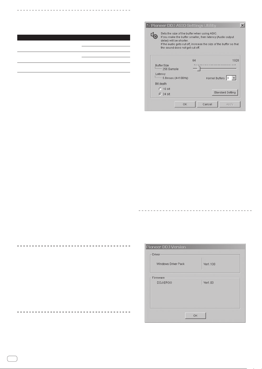
Click the Windows [Start] menu>[All Programs]>[Pioneer
]>[DDJ]>[Pioneer DDJ ASIO Settings Utility].
! If the buffer size is made large, drops in audio data (breaks in the
sound) occur less easily, but the time lag due to the delay in the
transfer of the audio data (latency) increases.
! If the kernel buffer number is made large, breaks in the sound occur
less easily, but the time lag due to latency increases.
! Operate referring to the procedure below to adjust the buffer size and
kernel buffer.
If there are no interruptions in the sound with the
default settings
1 Gradually decrease the buffer size, setting it to the minimum
value at which there are no interruptions in the sound.
2 Set the kernel buffer size to [2] and check whether there are inter-
ruptions in the sound.
— If there are interruptions in the sound, set the kernel buffer size to [3].
If there are interruptions in the sound with the default
settings
1 Set the kernel buffer size to [4], then set the buffer size to the
minimum value at which there are no interruptions in the sound.
Checking the version of the driver
software
Click the Windows [Start] menu>[All Programs]>[Pioneer]
>[DDJ]>[Pioneer DDJ Version Display Utility].
Connecting this unit and computer
1 Connect this unit to your computer via a USB cable.
For instructions on connections, see Connecting the input/output terminals on page 13.
2 Slide this unit’s [ON/OFF] switch to the [ON] position.
Turn on the power of this unit.
! The message [Installing device driver software] may appear when
this unit is first connected to the computer or when it is connected to
a different USB port on the computer. Wait a while until the message
[Your devices are ready for use] appears.
Adjusting the buffer size
This unit functions as an audio device conforming to the ASIO
standards.
! If an application using this unit as the default audio device (DJ
software, etc.) is running, quit that application before adjusting the
buffer size.
En
6
! You can check the firmware version of this unit on the screen.
! The firmware version is not displayed when this unit is not connected
to the computer or when this unit and computer are not properly
communicating.
Page 7
Checking the latest information on the
driver software
For the latest information on the driver software for exclusive use with
this unit, visit our website shown below.
http://pioneerdj.com/support/
About the TRAKTOR LE 2 software
TRAKTOR LE 2 is a DJ software application by Native Instruments. DJ
performances are possible by connecting the computer on which this
software is installed to this unit.
! For a comparison of the functions of the various versions of
TRAKTOR LE 2 and TRAKTOR 2, see the website below.
http://pioneerdj.com/support/
! The DDJ-ERGO-K supports TRAKTOR PRO 2 and TRAKTOR
SCRATCH PRO 2.
If you own TRAKTOR PRO 2 and TRAKTOR SCRATCH PRO 2, update
to the latest version of the software before using it.
Minimum operating environment
Supported operating
systems
Mac OS X 10.6.x
®
Windows
7
Home Premium/
Professional/
Ultimate
32-bit
version
Others
Hard disk Free space of 1 GB or greater
Optical drive Optical disc drive on which the CD-ROM can be read
USB port
Display resolution Resolution of 1 024 x 768 or greater
Internet connection
Recomended operating environment
Supported operating
systems
Mac OS X 10.7.x
®
Windows
7
Professional
! Full functionality is not guaranteed on all computers, even those meeting the
operating environment requirements described above.
! Even with the required memory indicated for the operating environment above,
lack of memory due to resident programs, the number of services, etc., could
prevent the software from offering optimal functionality and performance. In
such cases, free up sufficient memory. We recommend installing additional
memory for stable operation.
! Depending on the computer’s power-saving settings, etc., the CPU and hard
disk may not provide sufficient processing capabilities. For notebook computers in particular, make sure the computer is in the proper conditions to provide
constant high performance (for example by keeping the AC power connected)
when using TRAKTOR LE 2.
! Note that problems may arise with the functionality of TRAKTOR LE 2 depending
on other software running on your computer.
! A separate contract with and payment to a provider offering Internet services is
required.
64-bit
version
CPU and required memory
®
Intel
Core™ 2 Duo
2 GB or more of RAM
PC/AT-compatible computer with Intel
Core™ 2 Duo 2.0 GHz or greater or AMD
Athlon™ 64 x 2
2 GB or more of RAM
A USB 2.0 port is required to connect the computer
with this unit.
An Internet connection environment is required for
user registration with Native Instruments, to update the
TRAKTOR software, etc.
®
CPU and required memory
®
Intel
Core™ 2 Duo
4 GB or more of RAM
®
Intel
Core™ 2 or AMD Athlon™ X2
processor
4 GB or more of RAM
Installing the TRAKTOR LE 2 software
About the installation procedure (Windows)
1 Insert the included TRAKTOR LE 2 software CD-ROM
into the computer’s CD drive.
2 From the Windows [Start] menu, double-click the
[Computer (or My Computer)] > [Traktor 2] icon.
The contents of the CD-ROM are displayed.
3 Double-click [Traktor 2 Setup.exe].
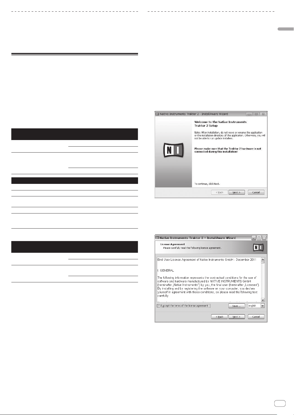
The TRAKTOR 2 installer is launched.
4 Once the TRAKTOR 2 installer is launched, click [Next].
— To return to the previous screen: Click [Back].
— To cancel installation: Click [Cancel].
5 Read the contents of the [License Agreement]
carefully, and if you agree, check [I accept the terms of
the license agreement], then click [Next].
If you do not agree to the terms of the [License Agreement], click
[Cancel] to cancel installation.
6 A screen for selecting the type of installation for
TRAKTOR 2 appears. Click [Next].
7 Choose where to install TRAKTOR 2, then click [Next].
To choose the normal place of installation, simply click [Next].
To install in a different location, click [Change...], choose the place of
installation, then click [Next].
8 Select the Native Instruments hardware driver, then
click [Next].
Check the check box for your hardware.
Before you start
En
7
Page 8
9 To install the Traktor Kontrol X1 or Traktor Kontrol S4
driver, check the check box, then click [Next].
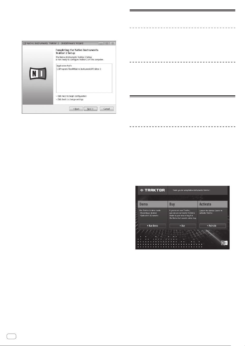
10 When the following screen appears, click [Next].
Installation begins.
The installation completed screen appears once installation is
completed.
11 Click [Finish].
This completes the installation procedure.
About the installation procedure (Mac OS X)
1 Insert the included TRAKTOR LE 2 software CD-ROM
into the computer’s CD drive.
The [Traktor 2] icon appears on the screen.
2 Double-click the [Traktor 2] icon.
The contents of the CD-ROM are displayed.
3 Double-click [Traktor 2 Installer.mpkg].
The TRAKTOR 2 installer is launched.
4 Once the TRAKTOR 2 installer is launched, click
[Continue].
5 Read the contents of the license agreement carefully,
then click [Continue].
6 If you agree to the contents of the usage agreement,
click [Agree].
If you do not agree to the contents of the usage agreement, click
[Disagree] to cancel installation.
7 Select the Native Instruments hardware driver, then
click [Continue].
Check the check box for your hardware.
8 Choose where to install TRAKTOR 2, then click
[Install].
To choose the normal place of installation, simply click [Install].
To install in a different location, click [Change Install Location...],
choose the place of installation, then click [Install].
Installation begins.
The installation completed screen appears once installation is
completed.
9 Click [Restart].
This completes the installation procedure.
Launching TRAKTOR 2
For Windows
From the Windows [Start] menu, open [All Programs] >
[Native Instruments] > [Traktor 2], then click the [Traktor
2] icon.
For Mac OS X
In Finder, open the [Application] folder, next open
[Native Instruments] > [Traktor 2], then double-click the
[Traktor] icon.
Performing product activation
To use TRAKTOR LE 2, first perform product activation (referred to simply as “activation” below) using Native Instruments SERVICE CENTER
(referred to simply as “SERVICE CENTER” below).
Launching the SERVICE CENTER
There are three ways to do this:
— Launching from the dialog displayed when TRAKTOR 2 is started up
— Launching from the TRAKTOR 2 [Help] menu
— Launching SERVICE CENTER directly
To launch from the dialog displayed when
TRAKTOR 2 is started up
1 Launch the TRAKTOR 2.
The screen below appears.
! Until activation is complete at the SERVICE CENTER, this dialog is
displayed each time TRAKTOR 2 is launched.
2 Select [Activate] and click.
— [Run Demo]: Launch TRAKTOR 2 in the demo mode.
— [Buy]: Purchase TRAKTOR 2 from the Native Instruments online
shop.
— [Activate]: SERVICE CENTER is launched.
To launch from the TRAKTOR 2 [Help] menu
From the TRAKTOR 2 [Help] menu, click [Launch Service
Center].
En
8
Page 9
To launch the SERVICE CENTER directly
For Windows
From the Windows [Start] menu, click the [Native Instruments] >
[Service Center] > [Service Center] icons.
For Mac OS X
In Finder, open the [Application] folder, then double-click the [Service
Center] > [Service Center] icons.
Activation procedure
— Online activation: When your computer is connected to the Internet
— Offline activation: When your computer is not connected to the
Internet
Online activation
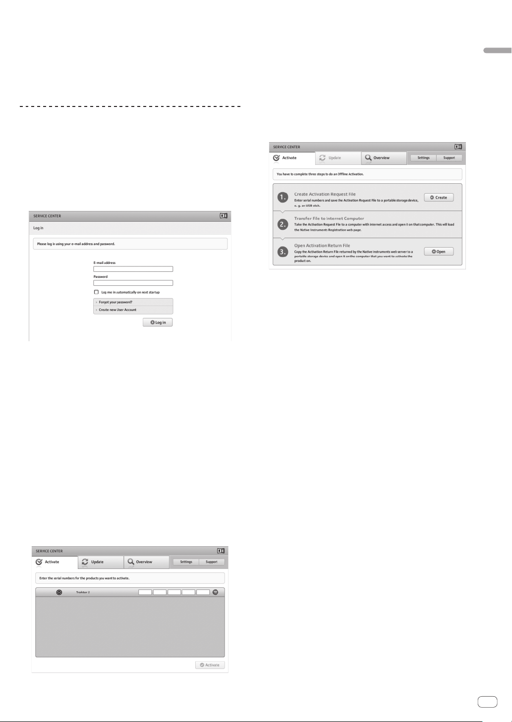
1 Launch the SERVICE CENTER.
The log-in screen is displayed.
2 Input your e-mail address and password, then click
[Log in].
! When logging in for the first time, you must create a new user
account.
When [Create new User Account] is clicked, the new user account
registration screen appears.
Input the required items (e-mail address, first and last names), select
your country/region, then click [Next].
When the registration information confirmation screen appears,
check the contents, then click [OK].
A password is sent to the e-mail address input on the form. Return to
the log-in screen and log in.
! The personal information input when registering a new user account
may be collected, processed and used based on the privacy policy on
the Native Instruments website.
PIONEER CORPORATION does not collect, process or use this per-
sonal information.
3 Input the serial number indicated on the package
of the TRAKTOR LE 2 software CD-ROM, then click
[Activate].
4 Once “Activated” is displayed, click [Exit].
Offline activation
To activate TRAKTOR LE 2 installed on a computer that is not connected
to the Internet, use SERVICE CENTER in the offline mode.
With this procedure, a second computer that can be connected to the
Internet is required.
1 Launch the SERVICE CENTER on the computer on
which TRAKTOR LE 2 is to be installed.
2 Click [Offline] at
[Continue without connecting to the internet].
3 Click [Create] at [Create Activation Request File].
4 Input the serial number indicated on the package of
the TRAKTOR LE 2 software CD-ROM, then click [Create].
A launch request file is created. Save this file on a USB device, etc.
5 Connect the USB device on which the launch request
file is saved to the computer that can be connected to
the Internet.
6 Double-click the launch request file on the computer
that can be connected to the Internet.
The web browser is launched.
7 Once the product activation screen appears, click
[Send].
8 Input your e-mail address and password, then click
[SUBMIT].
! When logging in for the first time, you must create a new user
account.
When [No - I do not have an NI account.] is checked and [SUBMIT]
is clicked, the new user account registration screen appears.
Input the required items (e-mail address, first and last names, street
address, city and postal code), select your country/region, then click
[NEXT].
When a survey screen appears, select answers to the various ques-
tions, then click [SUBMIT].
A password is sent to the e-mail address input on the form. Return to
the log-in screen and log in.
! The personal information input when registering a new user account
may be collected, processed and used based on the privacy policy on
the Native Instruments website.
PIONEER CORPORATION does not collect, process or use this per-
sonal information.
9 When the [Service Center Activation Page] appears,
click [NEXT].
10 Check that [Product] is [TRAKTOR LE 2] and [Status] is
[OK], then click [NEXT].
A launch return file is created. Save this file on a USB device, etc.
11 Launch the SERVICE CENTER on the computer on
which TRAKTOR LE 2 is to be installed.
12 Click [Offline] at
[Continue without connecting to the internet].
En
Before you start
9
Page 10
13 Click [Open] at [Open Activation Return File].
The launch return file is loaded.
14 Check in the SERVICE CENTER that product activation
has completed.
Updating the TRAKTOR 2 software
When the computer is connected to the Internet, TRAKTOR 2 software
can be updated by accessing the Native Instruments SERVICE CENTER
(referred to simply as “SERVICE CENTER” below).
1 Launch the SERVICE CENTER and log in.
For instructions on launching the SERVICE CENTER and logging in, see
Launching the SERVICE CENTER on page 8.
2 Click the [Update] tab.
Available updates are checked.
3 Check the check box.
Specify the update to be downloaded.
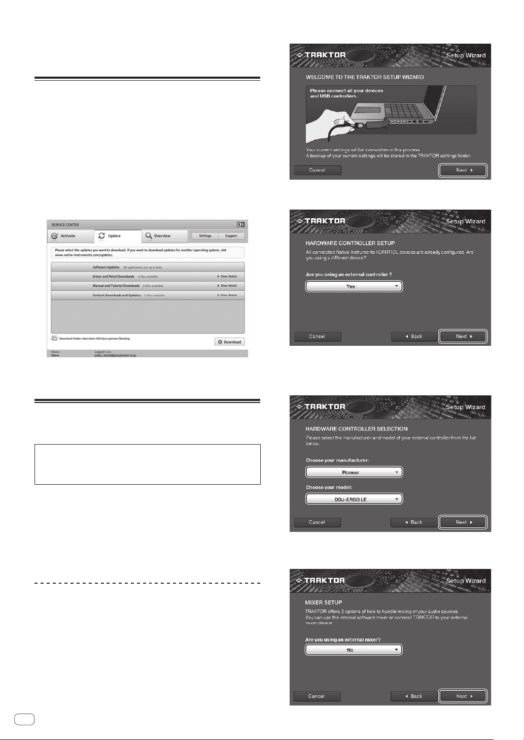
3 From the [Help] menu on the upper left of the screen,
open [Start Setup Wizard], then click [Next].
4 At the [Are you using an external controller?] item,
select [Yes], then click [Next].
4 Click [Download].
Updating begins.
Initial settings
The initial settings for TRAKTOR LE 2 can be made using the setup
wizard (Setup Wizard).
Cautions
! For Windows users, this unit’s driver software must be installed in
advance.
! All of TRAKTOR LE 2’s settings are reset to their defaults.
Before using, perform the following:
! Update this unit to the latest firmware version.
! For Windows users
Be sure to turn this unit’s power on before launching TRAKTOR LE 2.
If this unit’s power is turned on after launching TRAKTOR LE 2, the
DDJ-ASIO driver may not be recognized.
If the DDJ-ASIO driver is not recognized, close TRAKTOR LE 2 then
restart this unit.
Setting procedure
1 Connect this unit and the computer by USB cable,
then slide the [ON/OFF] switch to the [ON] side.
2 Once this unit starts up, launch TRAKTOR LE 2.
! Be sure to start up this unit before launching TRAKTOR LE 2.
5 Select [Pioneer] at the [Choose your manufacturer]
item and [DDJ-ERGO LE] at the [Choose your model]
item, then click [Next].
! When using TRAKTOR PRO 2, select [DDJ-ERGO].
6 At the [Are you using an external mixer?] item, select
[Yes] if using an external mixer, [No] if not, then click
[Next].
10
En
Page 11

7 Click [Finish] at the bottom right to complete the
setup wizard settings.
Cautions
The preferences are reset after the setup wizard settings are made.
When using the DDJ-ERGO-K, note that the audio settings below are
required at a minimum.
! Audio Setup
— Audio Device:
Pioneer DDJ ASIO (Windows 7)
PIONEER DDJ-ERGO (Mac OS X 10.6/10.7)
8 Open [File]>[Controller Manager...] if using windows,
[Traktor]>[Preferences]>[Controller Manager] if using
Mac OS X, then from [Device] under [Device Setup],
select [PIONEER DDJ-ERGO - Generic MIDI] and set
the device corresponding to this unit for [In-port] and
[Out-port].
Before you start
! Output Routing
— Mixing Mode:Internal
— Output Monitor:
L 3:DDJ-ERGO PHONES L
R 4:DDJ-ERGO PHONES R
— Output Master:
L 1:DDJ-ERGO MASTER L
R 2:DDJ-ERGO MASTER R
! Input Routing
The initial settings for TRAKTOR LE 2 are shown below.
To use external inputs with the initial settings, make the settings
below.
These settings are not required when not using external inputs.
— Input Aux:
L(Mono) 1:DDJ-ERGO AUX/MIC L
R 2:DDJ-ERGO AUX/MIC R
9 Close TRAKTOR 2, turn this unit’s power off then back
on, then relaunch TRAKTOR 2.
This completes all of the settings.
En
11
Page 12

Connections
8a
Be sure the power is off when connecting equipment and changing connections.
Be sure to use the USB cable included with this product.
Refer to the operating instructions for the component to be connected.
With this unit, the power is supplied by USB bus power. The unit can be used simply by connecting it to a computer using the USB cable.
! Connect this unit and the computer directly using the included USB cable.
! Connect the computer to which this unit is to be connected to an AC power supply.
! A USB hub cannot be used.
! In cases like the ones below, the power may be insufficient and this unit may not operate on USB bus power.
— When the computer’s USB power supply capacity is insufficient.
— When other USB devices are connected to the computer.
— When headphones with an impedance of less than 32 W are connected.
— When headphones are simultaneously connected to the stereo phone jack and the stereo mini-phone jack.
— When a monaural jack is connected to the [PHONES] terminal.
! If this unit cannot be operated on USB bus power, it may operate in the emergency mode (with limited functions).
The following limitations apply in the emergency mode:
— The volume of the headphones will be lower.
— The [DECK] button on the selected deck flashes.
Names of terminals
Rear panel
MASTER OUT1 (TRS)
RLRL
MASTER OUT2
VOL
AUX
MIC
41 72653
1 MASTER OUT 1 terminals
Connect powered speakers, etc., here.
This is a TRS phone jack, so both balanced and unbalanced outputs
are supported.
! The sound will be distorted if the level is raised too high when
using unbalanced outputs.
2 MASTER OUT 2 terminals
Connect to a power amplifier, etc.
3 MIC terminal
Connects a microphone here.
4 MIC VOL control
Adjusts the audio level input to the [MIC] terminal.
5 AUX/MIC selector switch
Switches the audio input between the external device and the
microphone.
— [AUX]: The external device connected to the [AUX] terminals is
selected.
— [MIC]: The microphone connected to the [MIC] terminal is
selected.
! The sound input to the [MIC] and [AUX] terminals is mixed to the
[MASTER OUT] sound.
AUX INMICVOL INPUT SELECT
RL
ON OFF USB
9
6 AUX IN VOL control
Adjusts the audio level input to the [AUX IN] terminals.
7 AUX IN terminals
Connect to the output terminal of an external device (sampler, portable audio device, etc.)
8 Kensington security slot
9 ON/OFF switch
Turns this unit’s power on and off.
a USB terminal
Connects to a computer.
! Connect this unit and the computer directly using the included
USB cable.
! A USB hub cannot be used.
12
En
Page 13

Front panel
Component, amplifier,
1
PHONES
1 PHONES terminals
Connect headphones here.
Both stereo phone plugs (Ø 6.3 mm) and stereo mini phone plugs (Ø
3.5 mm) can be used.
Connecting the input/output terminals
Rear panel
powered speaker, etc.
To audio input
terminals
MASTER OUT1 (TRS)
RLRL
R
MASTER OUT2
L
Microphone
Microphone
cable
To microphone
VOL
AUX
MIC
To audio output
L
R
AUX INMICVOL INPUT SELECT
RL
! Connect headphones with an impedance of 32 W or more.
Headphones with an impedance of less than 32 W are not
supported.
! Do not connect headphones simultaneously to the stereo phone
jack and the stereo mini-phone jack.
Portable
audio device
Computer
terminals
ON OFF USB
Connections
Front panel
Headphones cord
PHONES
To headphones
Headphones
En
13
Page 14

Part names and functions
5
3
43
The part functions and screen images given here are based on TRAKTOR PRO 2 functions.
Explanations of TRAKTOR PRO 2 functions are indicated
Also refer to the TRAKTOR 2 operating instructions. The TRAKTOR 2 operating instructions can be viewed from the TRAKTOR PRO 2 help menu.
2-deck displays are used for the included TRAKTOR LE 2.
Control panel
When TRAKTOR PRO 2 is launched for the first time, the display layout
is set to [Essential].
To display all of the parts described below, select [Mixer] with the layout
selector.
1 Browser (page 15)
2 Deck (page 15)
3 Mixer (page 17)
4 Effect (page 18)
5 Loop recorder (page 18)
TRAKTOR PRO 2
.
Layout selector
Layout selector
4
2
1
MINMAX
F2 F3
AUTO LOOP
MOVE GRID
IN OUT
SHIFT
CUE
F1
451
FX1
CONTROL
MINMAX1MINMAX2MINMAX3MINMAX
123
ON
SAMPLER
DELETE
HOT CUE /
1234
REV
4
2
PUSH
BROWSE VIEW
DECK
CA
FILTER
LPF HPF
1
SAMPLE VOL
VINYLKEYLOCK
S
E
A
R
C
H
PULSE
MODE
TEMPO
0
SYNC
MASTER
FWD
TREE FLD OPEN
LOAD
GAIN
FUNCTION
MIN MAX
FX
HI
2
TEMPO
PANGE
REC
MIX
MIN MAX
MID
CUEMASTE
VOL
MIN MAX
LOW
CUEMASTE
CUE
MIN MAX
DJ CONTROLLER
10
9
8
7
6
5
4
3
2
1
0
LOAD
GAIN
MIN MAX
MIN MAX
MID
MIN MAX
LOW
MIN MAX
DECK
BD
FILTER
LPF HPF
FX
HI
12
AUTO LOOP
MOVE GRID
IN
SHIFT
10
9
8
7
6
5
4
CUE
3
2
1
0
OUT
REV
FX2
CONTROL
MIN MAX1MIN MAX2MIN MAX3MIN MAX
123
ON
SAMPLER
DELETE
HOT CUE /
1234
MASTER VOL
MIN MAX
AUX / MIC VOL
MIN MAX
SAMPLE VOL
VINYL KEYLOCK
S
E
A
R
C
H
PULSE
TEMPO
MODE
PANGE
TEMPO
0
SYNC
MASTER
FWD
14
23 2
En
Page 15

1 Browser
BD
B
BROWSEVIEW
TREE FLD OPEN
LOAD
GAIN
12 2
PUSH
LOAD
GAIN
1 Rotary selector
! Turn:
The cursor moves in section A of the above diagram.
! Press:
The [BROWSE] area’s magnified display turns on and off.
! [SHIFT] + turn:
The cursor moves in section B of the above diagram.
2 Deck
7
F1
MIN MAX
F2 F3
CONTROL
MIN MAX1MIN MAX2MIN MAX3MIN MAX
ON
e
AUTO LOOP
6
5
4
3
2
1
MOVE GRID
IN OUT
SHIFT
CUE
REV
! The TRAKTOR 2 decks consist of the TRACK DECK and the REMIX
DECK.
! Initially, TRACK DECK is assigned to DECK A(B), REMIX DECK to
DECK C(D), but this can be changed as desired.
! With TRAKTOR LE 2, the REMIX DECK cannot be used.
! The REMIX DECK can be used if you upgrade to TRAKTOR PRO 2
(for a fee).
FX1
123
SAMPLER
DELETE
HOT CUE /
1234
S
E
A
R
C
H
FWD
DECK
CA
FILTER
LPF HPF
FX
1
2
SAMPLE VOL
KEYLOCK
VINYL
PULSE
TEMPO
MODE
PANGE
TEMPO
0
SYNC
MASTER
DECK
8
f
9
a
b
c
d
A
! [SHIFT] + press:
Folders in section B of the above diagram open and close.
2 LOAD button
Loads the track selected with the cursor in each of the decks.
TRACK DECK
1 f button
Uses this to play/pause tracks.
2 CUE button
! Press:
Sets a cue point or moves the cue point.
! [SHIFT] + press:
The playing position moves to the beginning of the track.
3 SHIFT button
When another button is pressed while pressing the [SHIFT] button, a
different function is called out.
4 IN button
! Press:
Sets the position at which loop playback starts (the loop in point).
! [SHIFT] + press:
TRAKTOR PRO 2
Moves the loop playback section one beat towards the beginning
of the track.
5 OUT button
! Press:
Sets the position at which loop playback ends (the loop out
point).
! [SHIFT] + press:
TRAKTOR PRO 2
Moves the loop playback section one beat towards the end of the
track.
Part names and functions
En
15
Page 16

6 AUTO LOOP (MOVE GRID) control
TRAKTOR PRO 2
! Turn:
Changes the width of the loop playback section.
! Press:
Turns loop playback on and off.
! [SHIFT] + turn:
Moves the beat grid position.
! [SHIFT] + press:
Switches loop playback on/off.
7 DECK buttons
Switch the deck to be operated.
8 HOT CUE/DELETE buttons
TRAKTOR PRO 2
! Press:
Set hot cue points and calls out hot cues.
! [SHIFT] + press:
Delete the hot cue set for that button.
9 KEYLOCK (TEMPO RANGE) button
! Press:
Turns the key lock function on and off.
! [SHIFT] + press:
The [TEMPO] slider’s range of variation switches each time this
is pressed.
a VINYL (PULSE MODE) button
! Press:
This switches the [VINYL] mode on/off.
! [SHIFT] + press:
Switches the jog dials’ illumination mode (Pulse Mode).
b TEMPO slider
Adjusts the playing speed.
c SYNC (MASTER) button
! Press:
Synchronizes to the master deck’s tempo.
! [SHIFT] + press:
Sets the master deck for synchronization.
d Jog dial
! Scratch
When the [VINYL] mode is turned on and the jog dial is turned
while pressing on its top, the track is played according to the
direction and speed at which the jog dial is turned.
! Pitch bend
The playing speed can be adjusted by turning the outer part of
the jog dial during playback.
The top of the jog dial has an embedded switch. Do not place objects
on the jog dial or subject it to strong forces. Also note that water or
other liquids getting into the set will lead to malfunction.
REMIX DECK
TRAKTOR PRO 2
The maximum number of sample slots that can be operated with this
unit is 4 per REMIX DECK.
1 f button
Plays all sample slots at once. When pressed during playback, stops
playback of all sample slots.
2 CUE button
Triggers all samples at once.
3 SHIFT button
When another button is pressed while pressing the [SHIFT] button, a
different function is called out.
4 IN button
Sets sample playback to the one-shot mode for all samples at once.
After the samples are played once, sample playback stops.
5 OUT button
Sets sample playback to the loop mode for all samples at once. The
samples are played in a loop.
6 AUTO LOOP (MOVE GRID) control
! Turn:
Halves or doubles the length of all the samples at once.
! Press:
Resets the loop size for all samples at once.
7 DECK buttons
Switches the deck to be operated.
8 HOT CUE/DELETE buttons
! Press:
When pressed during playback, playback starts from the
beginning.
! [SHIFT] + press:
Turn the sample slot individual control mode on and off.
Only slots whose indicators are flashing can be controlled.
9 KEYLOCK (TEMPO RANGE) button
Turns the key lock function on and off for all sample slots at once.
b TEMPO slider
Adjusts the playing speed of all samples at once.
c SYNC (MASTER) button
Synchronizes the phase of all samples at once.
d Jog dial
During playback, turn the jog dial while pressing down on its top.
! Scratch
When the [VINYL] mode is on, the source is played according to
the direction and speed at which the jog dial is turned.
! Pitch bend
When the [VINYL] mode is off, the playing speed can be
adjusted.
e SAMPLER button
! Press:
Starts/stops playback of the sample.
The sample is loaded from the TRACK DECK with the REMIX
DECK starting from empty.
When the sample is playing, playback returns to the beginning of
the sample and continues.
During loop playback, mutes and unmutes the sound.
! [SHIFT] + press:
When a sample is playing, playback returns to the beginning of
the sample and stops.
The sample is loaded from the list with the REMIX DECK starting
from empty. When pressed again, the sample is deleted from the
REMIX DECK.
f SAMPLE VOL control
! Turn:
Adjusts the audio level of all the sample slots.
! Press:
Resets the audio level of all the sample slots.
! [SHIFT] + turn:
Applies the filter to all the sample slots.
! [SHIFT] + press:
Resets the filter for all the sample slots.
En
16
Page 17

3 Mixer
GAIN
FUNCTION
MIN MAX
HI
MIN MAX
MID
MIN MAX
LOW
MIN MAX
CUE MASTE
CUE MASTE
DJ CONTROLLER
7 7
10
9
8
7
6
5
4
3
2
1
0
GAIN
3
4
MIN MAX
HI
REC
MIX
5
MIN MAX
MID
VOL
6
MIN MAX
LOW
CUE
MIN MAX
8
9
10
9
8
7
6
5
4
3
2
1
0
1
2
MASTER VOL
MIN MAX
AUX / MIC VOL
MIN MAX
a
1 MASTER VOL control
Adjusts the sound level output from the master.
2 AUX/MIC VOL control
Adjusts the audio output level of the [AUX IN] and [MIC] terminals.
3 GAIN controls
Adjust the sound level input to the various decks.
4 FUNCTION (REC) button
! Press:
Loads the track selected with the cursor into the preview player
and plays it.
! [SHIFT] + press:
TRAKTOR PRO 2
Clicks this to start/stop recording.
5 HEADPHONES MIX control
Adjusts the balance of the monitor volume between the sound of the
deck whose [CUE
] button is pressed and the master sound.
Part names and functions
6 HEADPHONES VOL control
Adjusts the audio level output from the [PHONES] terminal.
7 EQ (HI, MID, LOW) controls
These adjust the sound quality input to the various decks.
[HI] (treble range), [MID] (middle range), [LOW] (low range)
8 CUE (Headphones cue buttons)
Use this to monitor the sound of the respective decks over the
headphones.
9 Channel faders
Adjust the sound level output from the various decks.
a Crossfader
Switches the sound of the decks assigned to the left and right sides
of the crossfader for output.
Do not pull on the channel fader and crossfader knobs with excessive
force. The knobs have a structure by which they cannot be pulled off
easily. Pulling the knobs strongly may result in damaging the unit.
En
17
Page 18

4 Effect
TRAKTOR PRO 2
[4][8][16][32]
With TRAKTOR LE 2, [FX1-1] and [FX2-1] can be used, with [FX1-1] fixed
to deck A, [FX2-1] fixed to deck B. [FX1-2], [FX1-3], [FX2-2] and [FX2-3]
cannot be used.
1 3
CONTROL
MIN MAX1MIN MAX2MIN MAX3MIN MAX
ON
4
[Group] mode effect panel
! For TRAKTOR LE 2
Only one effect can be controlled.
! For TRAKTOR PRO 2
Three effects can be controlled simultaneously.
2
FX1
123
SAMPLER
DELETE
HOT CUE /
5
DECK
CA
FILTER
LPFHPF
FX
1
2
SAMPLE VOL
6
5 Effect parameter buttons
The associated functions differ according to the TRAKTOR 2 effect
panel mode.
— [Group] mode: Switches the various effects on/off.
— [Single] mode:
TRAKTOR PRO 2
When the effect control [1] button is pressed, all the effect set-
ting values return to the default setting values.
When effect control buttons [2] and [3] are pressed, the various
parameters switch between on and off. The types of parameters
differ according to the effect.
6 Effect assign buttons
Press the [1] or [2] button to assign TRAKTOR PRO 2 effect unit
[FX1] or [FX2] to the deck.
! With TRAKTOR LE 2, the effect assignments cannot be changed.
5 Loop recorder
TRAKTOR PRO 2
1
F1
MIN MAX
F2 F3
[Single] mode effect panel
TRAKTOR PRO 2
! TRAKTOR 2 effects include the [Group] mode and [Single] mode.
! With TRAKTOR LE 2, the [Single] mode cannot be selected.
! When you upgrade to TRAKTOR PRO 2 (for a fee), the effect panel
can be switched to the [Single] mode.
1 CONTROL dial
Changes the balance between the effect sound and original sound.
! [SHIFT] + turn:
TRAKTOR PRO 2
In the [Single] mode, switches the effect type.
2 Effect parameter controls
The associated functions differ according to the TRAKTOR 2 effect
panel mode.
— [Group] mode: Adjusts the parameters of the various effects.
— [Single] mode:
TRAKTOR PRO 2
Adjusts the various parameters of the selected effect.
! [SHIFT] + turn:
In the [Group] mode, switches the effect type.
3 FILTER control
! Turns clockwise to apply the high pass filter.
! Turns counterclockwise to apply the low pass filter.
4 FX ON button
TRAKTOR PRO 2
This button is for switching the effects exclusively for the [Single]
mode on and off.
! [SHIFT] + press:
Switches to the [Group] or [Single] mode for the effects.
2 3
! The loop recorder function cannot be used with TRAKTOR LE 2.
When you upgrade to TRAKTOR PRO 2 (for a fee), the loop recorder
function can be used.
1 F1 control
Adjusts the balance of the volume between the loop sound and main
sound.
2 F2 button
! Press:
Starts/stops loop recording.
When pressed during playback, overdubbing is possible.
! [SHIFT] + press:
Switches the recorded loop size.
3 F3 button
! Press:
Starts/stops playback of the recorded loop.
! [SHIFT] + press:
When pressed while the loop recorder is recording, the recording
is canceled and started over (UNDO). When pressed again at this
time, the loop recorder returns to the recording mode (REDO).
When pressed while the loop recorder is stopped, all of the con-
tents are deleted (DEL).
En
18
Page 19

Basic Operation
Starting the system
Starting this unit
1 Connect this unit to your computer via a USB cable.
MASTER OUT1 (TRS)
MASTER OUT2
RLRL
2 Boot up the connected computer.
3 Slide this unit’s [ON/OFF] switch to the [ON] position.
AUX INVOLINPUT SELECT
VOL
RL
MIC
AUX
Turn on the power of this unit.
! The message [Installing device driver software] may appear when
this unit is first connected to the computer or when it is connected to
a different USB port on the computer. Wait a while until the message
[Your devices are ready for use] appears.
4 Turn on the connected microphone and external
equipment.
Launching TRAKTOR LE 2
When this unit has just started, wait for the illumination to stop before
launching TRAKTOR LE 2.
For Windows
From the Windows [Start] menu, open [All Programs] >
[Native Instruments] > [Traktor 2], then click the [Traktor
2] icon.
For Mac OS X
AUX INMICVOL INPUT SELECT
VOL
RL
MIC
AUX
ON
OFFUSB
OFF USB
ON
3 Press the [LOAD] button to load the selected track
onto the deck.
4 Press the [f] button to play the track.
! When this button is pressed again during playback, playback
pauses.
Basic Operation
Outputting sound
! Set the volume of the power amplifiers connected to the [MASTER
OUT 1] and [MASTER OUT 2] terminals to an appropriate level. Note
that if the volume is set too high, the output sound could be very
loud.
1 Operate the [GAIN] control and the channel faders to
adjust the audio level output from the respective decks.
2 Operate the crossfader to switch the deck whose
sound is output from the speakers.
— Left edge: Sound is output from deck [A] or [C].
— Center: The sound of all the decks is mixed and output.
— Right edge: Sound is output from deck [B] or [D].
3 Turn the [MASTER VOL] control to adjust the audio
level of the speakers.
Monitoring sound with headphones
1 Connect headphones to the [PHONES] terminal.
2 Press the headphones [CUE] button for the deck you
want to monitor.
3 Turn the [HEADPHONES MIX] control.
— Turn counterclockwise: The sound of the deck for which the
headphones [CUE] button is pressed becomes relatively louder.
— Center position: The sound of the deck for which the headphones
[CUE] button is pressed and the [MASTER OUT 1, MASTER OUT
2] sound have the same volume.
— When turned clockwise: The volume of [MASTER OUT 1] and
[MASTER OUT 2] become relatively louder.
4 Turn the [HEADPHONES VOL] control.
The sound of the deck for which the headphones [CUE] button is pressed
is output from the headphones.
! When the headphones [CUE] button is pressed again, monitoring is
canceled.
In Finder, open the [Application] folder, next open
[Native Instruments] > [Traktor 2], then double-click the
[Traktor] icon.
Loading tracks and playing them
The following example describes the procedure for playing tracks with a
2-deck layout.
1 Turn the rotary selector while pressing the [SHIFT]
button to select a folder or item.
! When a folder or item with the [+] mark is selected and the rotary
selector is pressed while pressing the [SHIFT] button, that folder or
item is opened or closed.
2 Release the [SHIFT] button then turn the rotary
selector to select the track.
Mixing
1 Operate the [TEMPO] slider to match the playing
speed on one deck to the playing speed on the other
deck.
! Move towards the + (front) side: The playing speed increases.
! Move towards the – (back) side: The playing speed decreases.
2 If the beats of the two decks are off, use the jog dial’s
pitch bend function to correct for this offset.
The playing speed can be adjusted by turning the outer part of the jog
dial during playback.
— Spin clockwise: The playing speed increases.
— Spin counterclockwise: The playing speed decreases.
— Stop spinning: Playback at the normal speed resumes.
! When the [VINYL] mode is off, the playing speed can also be
adjusted by turning the jog dial while pressing on its top.
En
19
Page 20

! When the [SYNC (MASTER)] button is pressed, the playing speeds
and beats of the two decks are synchronized instantaneously.
3 Operate the channel faders or crossfader to mix the
sound of the two decks and switch between them.
Inputting the sound of an external device or microphone
The sound of the external device connected to the [AUX IN] terminals
or the sound of the microphone connected to the [MIC] terminal can be
mixed.
1 Connect the external device to the [AUX IN] or [MIC]
terminal.
2 Switch the [AUX, MIC] selector switch.
— [AUX]: Selects the external device connected to the [AUX IN]
terminals.
— [MIC]: Selects the microphone connected to the [MIC] terminal.
3 Make the TRAKTOR LE 2 software’s [Preferences] >
[Input Routing] setting.
Set [Input Aux] as shown below.
— [L(Mono)]:DDJ-ERGO AUX/MIC L
— [R]:DDJ-ERGO AUX/MIC R
4 Adjust the audio level input to the [AUX IN] or [MIC]
terminals.
— Turn the [MIC VOL] control on the main unit’s rear panel: The
[MIC] terminals’ input audio level is adjusted.
— Turn the [AUX IN VOL] control on the main unit’s rear panel: The
[AUX IN] terminals’ input audio level is adjusted.
Pioneer DJ player: Set near the center position.
Portable audio player or other device with low volume: Set clock-
wise of the center position.
5 Turn this unit’s [AUX/MIC VOL] control.
Turn this unit’s [AUX/MIC VOL] control to set the volume to a suitable
level.
Quitting the system
1 Quit TRAKTOR LE 2.
2 Slide this unit’s [ON/OFF] switch to the [OFF] position.
3 Disconnect the USB cable from your computer.
4 Turn off the connected microphone and external
equipment.
20
En
Page 21

Advanced Operation
Using the CUE function
1 In the pause mode, press the [CUE] button to set a cue
point at the position at which playback is paused.
2 When the [CUE] button is pressed during playback,
playback returns to the cue point that was set directly
before and pauses (Back Cue).
3 After returning to the cue point, keep pressing the
[CUE] button to continue playing (Cue Sampler).
Using the LOOP function
Manual looping
1 During playback, press the [IN] button to set the loop
in point.
2 Press the [OUT] button to set the loop out point and
start loop playback.
! When the [OUT] button is pressed during loop playback, loop play-
back is canceled.
Auto looping
— Pulse Mode Normal: The white illumination lights when the top of
the jog dial is pressed.
! The illumination mode setting is not cleared when this unit’s power
is turned off. When the power is next turned on, the unit starts in the
mode that was set before the power was turned off.
Advanced Operation
1 During playback, turn the [AUTO LOOP] control to set
the length for loop playback in number of beats.
2 Press the [AUTO LOOP] control to start loop playback.
! The length of the loop can be changed by turning the [AUTO LOOP]
control during loop playback.
! When the [AUTO LOOP] control is pressed during loop playback,
loop playback is canceled.
Using the EFFECT function
Separate audio effects can be applied to the respective decks.
1 Turn an effect parameter control while pressing the
[SHIFT] button to select the effect type.
2 Press an effect parameter button.
3 Turn the effect parameter controls to adjust the
parameters of the respective effects.
Switching the jog dials’ illumination mode
This unit is equipped with two types of illumination modes for the jog
dials.
Press the [VINYL (PULSE MODE)] button while pressing
the [SHIFT] button to switch the illumination mode.
— Pulse Mode Active: The offset of the beat grid is indicated by the
white illumination of the jog dials. The illumination is brightest
for the master deck and decks for which the beat grid matches.
The jog dials’ illumination also lights in association with the
operation of the [FILTER] control.
En
21
Page 22

List of MIDI Messages
With TRAKTOR 2, MIDI messages for assigning TRAKTOR 2 functions to to MIDI are expressed “Note1 + English scale2” or “CC3 + control number”.
On the table below, the MIDI messages output from this unit’s buttons and controls are indicated in the same way as in TRAKTOR 2.
1 “Note” is a MIDI term used when pressing or releasing notes on a piano or other keyboard.
2 The English scale indicates the tones using letters C, D, E, F, G, A and B and “#” indicating halftones.
3 “CC” is the abbreviation of “control change”. A control change is a type of MIDI signal used to transmit various types of control information, such as
timbre, volume, etc.
On this unit, values from 0 to 127 are output as CC mainly when controls and faders are operated. CC are also output when certain buttons are
operated.
! When operated while pressing the [SHIFT] button, the code for when the [SHIFT] button is on is set.
! MIDI messages cannot be assigned to the [SHIFT] button.
With this unit, the various sections are connected to the MIDI channels shown below.
MIDI channel
Deck A 1
Deck B 2
Deck C 3
Deck D 4
Effect A/C 5
Effect B/D 6
Browser, mixer, global section 7
Sample slot 1 8
Sample slot 2 9
Sample slot 3 10
Sample slot 4 11
We do not recommend using MIDI channels 12 and 13.
1 Browser
SW Name Deck type
Rotary selector (turn)
Rotary selector (press)
LOAD button (deck A)
LOAD button (deck B)
LOAD button (deck C)
LOAD button (deck D)
LOAD button
1 Only sent if slot is empty.
TRACK/SAMPLE
TRACK/SAMPLE
TRACK
TRACK
TRACK
TRACK
SAMPLE
MIDI message (this unit to computer)
When SHIFT button is off When SHIFT button is on
Ch CC/Note Number Ch CC/Note Number
07
07
07
07
07
07
08, 09, 10, 11
08, 09, 10, 11
08, 09, 10, 11
08, 09, 10, 11
CC
Note
Note
Note
Note
Note
Note
Note
Note
Note
64 07
F4 07
A#4 07
B4 07
C5 07
C#5 07
A#5 — — —
D6 — — —
F#6 — — —
A#6 — — —
CC
Note
Note
Note
Note
Note
Difference count value from when previously
100
F#4 OFF=0, ON=127
E6 OFF=0, ON=127
F6 OFF=0, ON=127
F#6 OFF=0, ON=127
G6 OFF=0, ON=127
operated
! Turn clockwise: 1 – (max) 30
! Turn counterclockwise: 127 – (min) 98
OFF=0, ON=127
Notes
1
22
En
Page 23

2 Deck
SW Name
f button
CUE button
IN button
OUT button
AUTO LOOP control (turn)
AUTO LOOP control (turned
clockwise)
AUTO LOOP control (turned
counterclockwise)
AUTO LOOP control (press)
DECK button
HOT CUE/DELETE 1 button
HOT CUE/DELETE 2 button
HOT CUE/DELETE 3 button
HOT CUE/DELETE 4 button
KEYLOCK (TEMPO RANGE)
button
VINYL (PULSE MODE) button
Deck
type
TRACK
SAMPLE
TRACK
SAMPLE
TRACK
SAMPLE
TRACK
SAMPLE
TRACK
SAMPLE
TRACK
SAMPLE
TRACK/
SAMPLE
TRACK
SAMPLE
TRACK
SAMPLE
TRACK
SAMPLE
TRACK
SAMPLE
TRACK
SAMPLE
TRACK
MIDI message (this unit to computer)
When SHIFT button is off When SHIFT button is on
Ch CC/Note Number Ch CC/Note Number
10, 11
Note
Note
Note
Note
Note
Note
Note
Note
Note
Note
Note
Note
Note
Note
Note
Note
Note
Note
Note
Note
Note
CC
Note
Note
Note
Note
Note
Note
Note
Note
Note
Note
Note
Note
Note
Note
Note
Note
Note
Note
Note
Note
Note
Note
Note
Note
Note
Note
Note
B1 01, 02, 03, 04
A#0 08, 09, 10, 11
B0 08, 09, 10, 11
C1 08, 09, 10, 11
C#1 08, 09, 10, 11
D9 — — — OFF=0, ON=127
C0 01, 02, 03, 04
A#4 08, 09, 10, 11
C5 08, 09, 10, 11
D5 08, 09, 10, 11
E5 08, 09, 10, 11
E0 01, 02, 03, 04
C4 08, 09, 10, 11
C#4 08, 09, 10, 11
D4 08, 09, 10, 11
D#4 08, 09, 10, 11
F0 01, 02, 03, 04
E7 08, 09, 10, 11
F7 08, 09, 10, 11
F#7 08, 09, 10, 11
G7 08, 09, 10, 11
19 01, 02, 03, 04 79 G5
C3 08, 09, 10, 11
C#3 08, 09, 10, 11
D3 08, 09, 10, 11
D#3 08, 09, 10, 11
E3 08, 09, 10, 11
F3 08, 09, 10, 11
F#3 08, 09, 10, 11
G3 08, 09, 10, 11
G#0 01, 02, 03, 04
G#3 08, 09, 10, 11
A3 08, 09, 10, 11
A#3 08, 09, 10, 11
B3 08, 09, 10, 11
F#8 — — — OFF=0, ON=127
A#2 01, 02, 03, 04
A#4 — — — OFF=0, ON=127
B2 01, 02, 03, 04
C5 — — — OFF=0, ON=127
C3 01, 02, 03, 04
D5 — — — OFF=0, ON=127
C#3 01, 02, 03, 04
E5 — — — OFF=0, ON=127
D1 01, 02, 03, 04
G#1 — — —
A1 — — —
A#1 — — —
B1 — — —
01, 02, 03, 04
08, 09, 10, 11
08, 09, 10, 11
08, 09, 10, 11
08, 09, 10, 11
08, 09, 10, 11
01, 02, 03, 04
08, 09, 10, 11
08, 09, 10, 11
08, 09, 10, 11
08, 09, 10, 11
01, 02, 03, 04
08, 09, 10, 11
08, 09, 10, 11
08, 09, 10, 11
08, 09, 10, 11
01, 02, 03, 04
08, 09, 10, 11
08, 09, 10, 11
08, 09, 10, 11
08, 09, 10, 11
01, 02, 03, 04
08, 09, 10, 11
08, 09, 10, 11
08, 09, 10, 11
08, 09, 10, 11
08, 09, 10, 11
08, 09, 10, 11
08, 09, 10, 11
08, 09, 10, 11
01, 02, 03, 04
08, 09, 10, 11
08, 09, 10, 11
08, 09, 10, 11
08, 09, 10, 11
01, 02, 03, 04
01, 02, 03, 04
08, 09, 10, 11
01, 02, 03, 04
08, 09, 10, 11
01, 02, 03, 04
08, 09, 10, 11
01, 02, 03, 04
08, 09, 10, 11
01, 02, 03, 04
08, 09,
08, 09, 10, 11
08, 09, 10, 11
08, 09, 10, 11
— — — — —
Note
Note
Note
Note
Note
Note
Note
Note
Note
Note
Note
Note
Note
Note
Note
Note
Note
Note
Note
Note
CC
CC
CC
CC
CC
CC
CC
CC
Note
Note
Note
Note
Note
Note
Note
Note
Note
Note
Note
Note
Note
B4 OFF=0, ON=127
G#0
A0
D1
D#1
C5 OFF=0, ON=127
E1
F1
F#1
G1
E5 OFF=0, ON=127
F#5
G5
G#5
A5
F5 OFF=0, ON=127
A#7
B7
C8
C#8
68
69
126
127
68
69
126
127
G#5 OFF=0, ON=127
C2
C#2
D2
D#2
B6 OFF=0, ON=127
C7 OFF=0, ON=127
C#7 OFF=0, ON=127
D7 OFF=0, ON=127
D#1
E1
F1
F#1
OFF=0, ON=127
OFF=0, ON=127
OFF=0, ON=127
OFF=0, ON=127
Difference count value from when previously operated
! Turn clockwise: 1 – (max) 30
! Turn counterclockwise: 127 – (min) 98
Difference count value from when previously operated
! Turn clockwise: 1 – (max) 30
Difference count value from when previously operated
! Turn counterclockwise: 127 – (min) 98
OFF=0, ON=127
OFF=0, ON=127
OFF=0, ON=127
Notes
2
3
2
List of MIDI Messages
2
2
2
2
2
4
2
En
23
Page 24

SW Name
TEMPO slider
SYNC (MASTER) button
Jog dial (when outer section
turned)
Jog dial (when top section
turned: [VINYL] mode on)
Jog dial (when top section
turned: [VINYL] mode off)
Jog dial (when top section
pressed: [VINYL] mode on)
Jog dial (when top section
pressed: [VINYL] mode off)
SAMPLER 1 button
SAMPLER 2 button
SAMPLER 3 button
SAMPLER 4 button
Deck
type
TRACK
TRACK
SAMPLE
TRACK
SAMPLE
TRACK
SAMPLE
TRACK
SAMPLE
TRACK
SAMPLE
TRACK
SAMPLE
TRACK
SAMPLE
TRACK
SAMPLE
TRACK
SAMPLE
TRACK
SAMPLE
MIDI message (this unit to computer)
When SHIFT button is off When SHIFT button is on
Ch CC/Note Number Ch CC/Note Number
01, 02, 03, 04
01, 02, 03, 04
08, 09, 10, 11
08, 09, 10, 11
08, 09, 10, 11
08, 09, 10, 11
01, 02, 03, 04
08, 09, 10, 11
08, 09, 10, 11
08, 09, 10, 11
08, 09, 10, 11
01, 02, 03, 04
08, 09, 10, 11
08, 09, 10, 11
08, 09, 10, 11
08, 09, 10, 11
01, 02, 03, 04
08, 09, 10, 11
08, 09, 10, 11
08, 09, 10, 11
08, 09, 10, 11
01, 02, 03, 04
08, 09, 10, 11
08, 09, 10, 11
08, 09, 10, 11
08, 09, 10, 11
01, 02, 03, 04
08, 09, 10, 11
08, 09, 10, 11
08, 09, 10, 11
08, 09, 10, 11
01, 02, 03, 04
08, 09, 10, 11
08, 09, 10, 11
08, 09, 10, 11
01, 02, 03, 04
08, 09, 10, 11
08, 09, 10, 11
08, 09, 10, 11
01, 02, 03, 04
08, 09, 10, 11
08, 09, 10, 11
08, 09, 10, 11
01, 02, 03, 04
08, 09, 10, 11
08, 09, 10, 11
08, 09, 10, 11
CC
CC
Note
Note
Note
Note
Note
CC
CC
CC
CC
CC
CC
CC
CC
CC
CC
CC
CC
CC
CC
CC
Note
Note
Note
Note
Note
Note
Note
Note
Note
Note
Note
Note
Note
Note
Note
Note
Note
Note
Note
Note
Note
Note
Note
Note
Note
Note
0
32
01, 02, 03, 04
E6 01, 02, 03, 04
D8 — — —
D#8 — — —
E8 — — —
F8 — — —
33 01, 02, 03, 04
0 — — —
1 — — —
2 — — —
3 — — —
34 01, 02, 03, 04
8 — — —
9 — — —
10 — — —
11 — — —
35 01, 02, 03, 04
12 — — —
13 — — —
14 — — —
15 — — —
F#3 01, 02, 03, 04
E1 — — —
F1 — — —
F#1 — — —
G1 — — —
G3 01, 02, 03, 04
E0 — — —
F#0 — — —
F0 — — —
G0 — — —
C4 01, 02, 03, 04
A#5 08, 09, 10, 11
C6 08, 09, 10, 11
E2 — — — OFF=0, ON=127
D4 01, 02, 03, 04
D6 08, 09, 10, 11
E6 08, 09, 10, 11
F2 — — — OFF=0, ON=127
E4 01, 02, 03, 04
F#6 08, 09, 10, 11
G#6 08, 09, 10, 11
F#2 — — — OFF=0, ON=127
F#4 01, 02, 03, 04
A#6 08, 09, 10, 11
C7 08, 09, 10, 11
G2 — — — OFF=0, ON=127
CC
CC
Note
CC
CC
CC
Note
Note
Note
Note
Note
Note
Note
Note
Note
Note
Note
Note
Note
Note
5
37
0–16383
0 at back, 16383 at front
G#6 OFF=0, ON=127
OFF=0, ON=127
Difference count value from when previ-
38
39
39
ously operated
! Turned clockwise: Count up from 64
! Turned counterclockwise: Count down
from 64
Difference count value from when previously operated
! Turned clockwise: Count up from 64
! Turned counterclockwise: Count down
from 64
Difference count value from when previously operated
! Turned clockwise: Count up from 64
! Turned counterclockwise: Count down
from 64
Difference count value from when previously operated
! Turned clockwise: Count up from 64
! Turned counterclockwise: Count down
from 64
Difference count value from when previously operated
! Turned clockwise: Count up from 64
! Turned counterclockwise: Count down
from 64
Difference count value from when previously operated
! Turned clockwise: Count up from 64
! Turned counterclockwise: Count down
from 64
G7 OFF=0, ON=127
OFF=0, ON=127
G7 OFF=0, ON=127
OFF=0, ON=127
C#4 OFF=0, ON=127
B5 OFF=0, ON=127
C#6 OFF=0, ON=127
D#4 OFF=0, ON=127
D#6 OFF=0, ON=127
F6 OFF=0, ON=127
F4 OFF=0, ON=127
G6 OFF=0, ON=127
A6 OFF=0, ON=127
G4 OFF=0, ON=127
B6 OFF=0, ON=127
C#7 OFF=0, ON=127
Notes
2
2
2
2
2
2
1
5
1
5
1
5
1
5
24
En
Page 25

SW Name
SAMPLE VOL control (turn)
SAMPLE VOL control (press)
1 Only sent if slot is empty.
2 Sent to selected slot (Individual Control Mode).
3 Sent when not in the Individual Control Mode.
4 When the [SHIFT] button is pressed, the four MIDI-IN messages are toggled and sent.
5 Only sent during playback in the one-shot mode.
Indicator name
f button
CUE button
IN button
OUT button
DECK button
HOT CUE/DELETE 1 button
HOT CUE/DELETE 2 button
HOT CUE/DELETE 3 button
HOT CUE/DELETE 4 button
KEYLOCK (TEMPO RANGE)
button
VINYL (PULSE MODE)
button
SYNC (MASTER) button
SAMPLER 1 button
SAMPLER 2 button
SAMPLER 3 button
SAMPLER 4 button
Deck
type
TRACK
SAMPLE
TRACK
SAMPLE
Deck
type
TRACK
TRACK
TRACK
TRACK
TRACK/
SAMPLE
TRACK
TRACK
TRACK
TRACK
TRACK
TRACK
TRACK
SAMPLE
TRACK
TRACK
TRACK
TRACK
When SHIFT button is off When SHIFT button is on
Ch CC/Note Number Ch CC/Note Number
01, 02, 03, 04
08, 09, 10, 11
08, 09, 10, 11
08, 09, 10, 11
08, 09, 10, 11
01, 02, 03, 04
08, 09, 10, 11
08, 09, 10, 11
08, 09, 10, 11
08, 09, 10, 11
When SHIFT button is off When SHIFT button is on
Ch CC/Note Number Ch CC/Note Number
01, 02, 03, 04
01, 02, 03, 04
01, 02, 03, 04
01, 02, 03, 04
01, 02, 03, 04
01, 02, 03, 04
01, 02, 03, 04
01, 02, 03, 04
01, 02, 03, 04
01, 02, 03, 04
— — — — —
01, 02, 03, 04
08, 09, 10, 11
01, 02, 03, 04
01, 02, 03, 04
01, 02, 03, 04
01, 02, 03, 04
MIDI message (this unit to computer)
CC
CC
CC
CC
CC
Note
Note
Note
Note
Note
68 01, 02, 03, 04
98 08, 09, 10, 11
99 08, 09, 10, 11
100 08, 09, 10, 11
101 08, 09, 10, 11
A4 01, 02, 03, 04
F#7 08, 09, 10, 11
G7 08, 09, 10, 11
G#7 08, 09, 10, 11
A7 08, 09, 10, 11
MIDI message (computer to this unit)
Note
Note
Note
Note
Note
Note
Note
Note
Note
Note
Note
Note
Note
Note
Note
Note
B1 01, 02, 03, 04
C0 01, 02, 03, 04
E0 01, 02, 03, 04
F0 01, 02, 03, 04
F#8 — — —
A#2 01, 02, 03, 04
B2 01, 02, 03, 04
C3 01, 02, 03, 04
C#3 01, 02, 03, 04
D1 01, 02, 03, 04
E6 01, 02, 03, 04
D8 — — — Red Off = 0, lit = 127
C4 01, 02, 03, 04
D4 01, 02, 03, 04
E4 01, 02, 03, 04
F#4 01, 02, 03, 04
CC
CC
CC
CC
CC
Note
Note
Note
Note
Note
Difference count value from when previ-
73
114
115
116
117
D5 OFF=0, ON=127
A#8
B8
C9
C#9
Note
Note
Note
Note
Note
Note
Note
Note
Note
Note
Note
Note
Note
Note
ously operated
! Turn clockwise: 1 – (max) 30
! Turn counterclockwise: 127 – (min) 98
Difference count value from when previously operated
! Turn clockwise: 1 – (max) 30
! Turn counterclockwise: 127 – (min) 98
OFF=0, ON=127
B4 Red Off = 0, lit = 127
C5 Red Off = 0, lit = 127
E5 Red Off = 0, lit = 127
F5 Red Off = 0, lit = 127
B6 Red Off = 0, lit = 127
C7 Red Off = 0, lit = 127
C#7 Red Off = 0, lit = 127
D7 Red Off = 0, lit = 127
D#1 Red Off = 0, lit = 127
G#6 Red Off = 0, lit = 127
C#4 Red Off = 0, lit = 127
D#4 Red Off = 0, lit = 127
F4 Red Off = 0, lit = 127
G4 Red Off = 0, lit = 127
2
2
Indicator
color
Decks
A/B – red,
decks C/D
– orange
Notes
List of MIDI Messages
Notes
Off = 0, lit = 127
En
25
Page 26

3 Mixer
SW Name
MASTER VOL control 07
AUX/MIC VOL control 07
Deck A 07
Deck B 07
GAIN control
Deck C 07
Deck D 07
FUNCTION (REC) button 07
HEADPHONES MIX control 07
HEADPHONES VOL control 07
Deck A 07
Deck B 07
EQ [HI] control
Deck C 07
Deck D 07
Deck A 07
Deck B 07
EQ [MID] control
Deck C 07
Deck D 07
Deck A 07
Deck B 07
EQ [LOW] control
Deck C 07
Deck D 07
Deck A 07
CUE
button)
(Headphones cue
Deck B 07
Deck C 07
Deck D 07
MIDI message (this unit to computer)
When SHIFT button is off When SHIFT button is on
Ch CC/Note Number Ch CC/Note Number
CC
CC
CC
CC
CC
CC
CC
CC
CC
CC
CC
CC
Note
CC
CC
CC
CC
CC
CC
CC
CC
CC
CC
CC
CC
CC
CC
CC
CC
CC
CC
CC
CC
CC
CC
CC
CC
CC
CC
CC
CC
Note
Note
Note
Note
0
32
20
52
3
35
4
36
5
37
6
38
F7 07
1
33
2
34
7
39
8
40
9
41
10
42
11
43
12
44
13
45
14
46
15
47
16
48
17
49
18
50
C6 — — — OFF=0, ON=127
C#6 — — — OFF=0, ON=127
D6 — — — OFF=0, ON=127
D#6 — — — OFF=0, ON=127
———
———
———
———
———
———
———
———
———
———
———
———
———
———
———
———
———
———
———
———
—
—
—
—
—
—
Note
—
—
—
—
—
—
—
—
—
—
—
—
—
—
—
—
—
—
—
—
—
—
—
—
—
—
F#7 OFF=0, ON=127
—
—
—
—
—
—
—
—
—
—
—
—
—
—
—
—
—
—
—
—
—
—
—
—
—
—
—
—
Notes
0–16383
When turned fully counterclockwise: 0 / When
turned fully clockwise: 16383
0–16383
When turned fully counterclockwise: 0 / When
turned fully clockwise: 16383
0–16383
When turned fully counterclockwise: 0 / When
turned fully clockwise: 16383
0–16383
When turned fully counterclockwise: 0 / When
turned fully clockwise: 16383
0–16383
When turned fully counterclockwise: 0 / When
turned fully clockwise: 16383
0–16383
When turned fully counterclockwise: 0 / When
turned fully clockwise: 16383
0–16383
When turned fully counterclockwise: 0 / When
turned fully clockwise: 16383
0–16383
When turned fully counterclockwise: 0 / When
turned fully clockwise: 16383
0–16383
When turned fully counterclockwise: 0 / When
turned fully clockwise: 16383
0–16383
When turned fully counterclockwise: 0 / When
turned fully clockwise: 16383
0–16383
When turned fully counterclockwise: 0 / When
turned fully clockwise: 16383
0–16383
When turned fully counterclockwise: 0 / When
turned fully clockwise: 16383
0–16383
When turned fully counterclockwise: 0 / When
turned fully clockwise: 16383
0–16383
When turned fully counterclockwise: 0 / When
turned fully clockwise: 16383
0–16383
When turned fully counterclockwise: 0 / When
turned fully clockwise: 16383
0–16383
When turned fully counterclockwise: 0 / When
turned fully clockwise: 16383
0–16383
When turned fully counterclockwise: 0 / When
turned fully clockwise: 16383
0–16383
When turned fully counterclockwise: 0 / When
turned fully clockwise: 16383
0–16383
When turned fully counterclockwise: 0 / When
turned fully clockwise: 16383
0–16383
When turned fully counterclockwise: 0 / When
turned fully clockwise: 16383
26
En
Page 27

SW Name
Deck A 07
Deck B 07
Channel fader
Deck C 07
Deck D 07
Crossfader 07
MIDI message (this unit to computer)
When SHIFT button is off When SHIFT button is on
Ch CC/Note Number Ch CC/Note Number
CC
CC
CC
CC
CC
CC
CC
CC
CC
CC
19
51
21
53
23
55
25
57
31
63
———
———
———
———
———
—
—
—
—
—
—
—
—
—
—
—
—
—
—
—
Notes
0–16383
When turned fully counterclockwise: 0 / When
turned fully clockwise: 16383
0–16383
When turned fully counterclockwise: 0 / When
turned fully clockwise: 16383
0–16383
When turned fully counterclockwise: 0 / When
turned fully clockwise: 16383
0–16383
When turned fully counterclockwise: 0 / When
turned fully clockwise: 16383
0–16383
0 at left side, 16383 at right side
Indicator name
FUNCTION (REC) button 07
Deck A 07
CUE
(Headphones cue button)
Deck B 07
Deck C 07
Deck D 07
4 Effect
SW Name
Group
CONTROL dial
Single
Group
Effect parameter control 1
Single
Group
Effect parameter control 2
Single
MIDI message (computer to this unit)
When SHIFT button is off When SHIFT button is on
Ch CC/Note Number Ch CC/Note Number
Note
Note
Note
Note
Note
F7 07
C6 — — — Red Off = 0, lit = 127
C#6 — — — Red Off = 0, lit = 127
D6 — — — Red Off = 0, lit = 127
D#6 — — — Red Off = 0, lit = 127
Note
F#7 Red Off = 0, lit = 127
MIDI message (this unit to computer)
When SHIFT button is off When SHIFT button is on
Ch CC/Note Number Ch CC/Note Number
CC
05
CC
CC
06
CC
CC
05
CC
CC
06
CC
CC
05
CC
CC
06
CC
CC
05
CC
CC
06
CC
CC
05
CC
CC
06
CC
CC
05
CC
CC
06
CC
0
32
0
32
8
40
8
40
2
34
2
34
10
42
10
42
4
36
4
36
12
44
12
44
CC
05
CC
CC
06
CC
CC
05
CC
CC
06
CC
CC
05
CC
CC
06
CC
CC
05
CC
CC
06
CC
CC
05
CC
CC
06
CC
CC
05
CC
CC
06
CC
16
48
16
48
24
56
24
56
18
50
18
50
26
58
26
58
20
52
20
52
28
60
28
60
Indicator
color
Notes
Notes
0–16383
When turned fully counterclockwise: 0 / When
turned fully clockwise: 16383
0–16383
When turned fully counterclockwise: 0 / When
turned fully clockwise: 16383
0–16383
When turned fully counterclockwise: 0 / When
turned fully clockwise: 16383
0–16383
When turned fully counterclockwise: 0 / When
turned fully clockwise: 16383
0–16383
When turned fully counterclockwise: 0 / When
turned fully clockwise: 16383
0–16383
When turned fully counterclockwise: 0 / When
turned fully clockwise: 16383
0–16383
When turned fully counterclockwise: 0 / When
turned fully clockwise: 16383
0–16383
When turned fully counterclockwise: 0 / When
turned fully clockwise: 16383
0–16383
When turned fully counterclockwise: 0 / When
turned fully clockwise: 16383
0–16383
When turned fully counterclockwise: 0 / When
turned fully clockwise: 16383
0–16383
When turned fully counterclockwise: 0 / When
turned fully clockwise: 16383
0–16383
When turned fully counterclockwise: 0 / When
turned fully clockwise: 16383
List of MIDI Messages
En
27
Page 28

SW Name
Effect parameter control 3
FILTER control
FX ON button
Effect parameter button 1
Effect parameter button 2
Effect parameter button 3
FX1 button
FX2 button
Group
Single
Deck A 07
Deck B 07
Deck C 07
Deck D 07
Group
Single
Group
Single
Group
Single
Group
Single
Deck A 07
Deck B 07
Deck C 07
Deck D 07
Deck A 07
Deck B 07
Deck C 07
Deck D 07
MIDI message (this unit to computer)
When SHIFT button is off When SHIFT button is on
Ch CC/Note Number Ch CC/Note Number
CC
05
CC
CC
06
CC
CC
05
CC
CC
06
CC
CC
CC
Note
CC
CC
Note
CC
CC
Note
CC
CC
Note
Note
05
Note
06
Note
05
Note
06
Note
05
Note
06
Note
05
Note
06
Note
05
Note
06
Note
05
Note
06
Note
05
Note
06
Note
05
Note
06
Note
Note
Note
Note
Note
Note
Note
Note
6
38
6
38
14
46
14
46
27
59
G#8 — — —
28
60
A8 — — —
29
61
A#8 — — —
30
62
B8 — — —
G4 05
G4 06
D5 05
D5 06
B4 05
B4 06
D#5 05
D#5 06
C5 05
C5 06
E5 05
E5 06
C#5 05
C#5 06
F5 05
F5 06
E5 — — — OFF=0, ON=127
F5 — — — OFF=0, ON=127
F#5 — — — OFF=0, ON=127
G5 — — — OFF=0, ON=127
G#5 — — — OFF=0, ON=127
A5 — — — OFF=0, ON=127
A#5 — — — OFF=0, ON=127
B5 — — — OFF=0, ON=127
05
06
05
06
———
———
———
———
CC
CC
CC
CC
CC
CC
CC
CC
—
—
—
—
Note
Note
Note
Note
Note
Note
Note
Note
Note
Note
Note
Note
Note
Note
Note
Note
22
54
22
54
30
62
30
62
—
—
—
—
—
—
—
—
E4 OFF=0, ON=127
E4 OFF=0, ON=127
F#7 OFF=0, ON=127
F#7 OFF=0, ON=127
D#7 OFF=0, ON=127
D#7 OFF=0, ON=127
G7 OFF=0, ON=127
G7 OFF=0, ON=127
E7 OFF=0, ON=127
E7 OFF=0, ON=127
G#7 OFF=0, ON=127
G#7 OFF=0, ON=127
F7 OFF=0, ON=127
F7 OFF=0, ON=127
A7 OFF=0, ON=127
A7 OFF=0, ON=127
Notes
0–16383
When turned fully counterclockwise: 0 / When
turned fully clockwise: 16383
0–16383
When turned fully counterclockwise: 0 / When
turned fully clockwise: 16383
0–16383
When turned fully counterclockwise: 0 / When
turned fully clockwise: 16383
0–16383
When turned fully counterclockwise: 0 / When
turned fully clockwise: 16383
0–16383
When turned fully counterclockwise: 0 / When
turned fully clockwise: 16383
Other than at center position: Note On sent
At center position: Note Off sent
0–16383
When turned fully counterclockwise: 0 / When
turned fully clockwise: 16383
Other than at center position: Note On sent
At center position: Note Off sent
0–16383
When turned fully counterclockwise: 0 / When
turned fully clockwise: 16383
Other than at center position: Note On sent
At center position: Note Off sent
0–16383
When turned fully counterclockwise: 0 / When
turned fully clockwise: 16383
Other than at center position: Note On sent
At center position: Note Off sent
28
En
Page 29

Indicator name
FX ON button
Effect parameter button 1
Effect parameter button 2
Effect parameter button 3
FX1 button
FX2 button
Group
Single
Group
Single
Group
Single
Group
Single
Deck A 07
Deck B 07
Deck C 07
Deck D 07
Deck A 07
Deck B 07
Deck C 07
Deck D 07
MIDI message (computer to this unit)
When SHIFT button is off When SHIFT button is on
Ch CC/Note Number Ch CC/Note Number
Note
05
Note
06
Note
05
Note
06
Note
05
Note
06
Note
05
Note
06
Note
05
Note
06
Note
05
Note
06
Note
05
Note
06
Note
05
Note
06
Note
Note
Note
Note
Note
Note
Note
Note
G4 05
G4 06
D5 05
D5 06
B4 05
B4 06
D#5 05
D#5 06
C5 05
C5 06
E5 05
E5 06
C#5 05
C#5 06
F5 05
F5 06
E5 — — — Red Off = 0, lit = 127
F5 — — — Red Off = 0, lit = 127
F#5 — — — Red Off = 0, lit = 127
G5 — — — Red Off = 0, lit = 127
G#5 — — — Red Off = 0, lit = 127
A5 — — — Red Off = 0, lit = 127
A#5 — — — Red Off = 0, lit = 127
B5 — — — Red Off = 0, lit = 127
Note
Note
Note
Note
Note
Note
Note
Note
Note
Note
Note
Note
Note
Note
Note
Note
E4 Red Off = 0, lit = 127
E4 Red Off = 0, lit = 127
F#7 Red Off = 0, lit = 127
F#7 Red Off = 0, lit = 127
D#7 Red Off = 0, lit = 127
D#7 Red Off = 0, lit = 127
G7 Red Off = 0, lit = 127
G7 Red Off = 0, lit = 127
E7 Red Off = 0, lit = 127
E7 Red Off = 0, lit = 127
G#7 Red Off = 0, lit = 127
G#7 Red Off = 0, lit = 127
F7 Red Off = 0, lit = 127
F7 Red Off = 0, lit = 127
A7 Red Off = 0, lit = 127
A7 Red Off = 0, lit = 127
Indicator
color
Notes
List of MIDI Messages
5 Loop recorder
SW Name
F1 control 07
F2 button 07
F3 button
1 Sent when the loop recorder is stopped.
2 Sent when the loop recorder is playing.
Indicator name
F2 button 07
F3 button 07
07
MIDI message (this unit to computer)
When SHIFT button is off When SHIFT button is on
Ch CC/Note Number Ch CC/Note Number
CC
CC
Note
Note
22
54
A7 07
B7 07
—
—
07
—
—
Note
Note
Note
—
—
A#7 OFF=0, ON=127
C8 OFF=0, ON=127
C#8 OFF=0, ON=127
MIDI message (computer to this unit)
When SHIFT button is off When SHIFT button is on
Ch CC/Note Number Ch CC/Note Number
Note
Note
A7 07
B7 07
Note
Note
A#7 Red Off = 0, lit = 127
C8 Red Off = 0, lit = 127
Notes
0–16383
When turned fully counterclockwise: 0 / When turned
fully clockwise: 16383
1
2
Indicator
color
Notes
En
29
Page 30

Additional information
Troubleshooting
! Incorrect operation is often mistaken for trouble or malfunction. If you think that there is something wrong with this component, check the points
below. Sometimes the trouble may lie in another component. Inspect the other components and electrical appliances being used. If the trouble
cannot be rectified after checking the items below, ask your nearest Pioneer authorized service center or your dealer to carry out repair work.
! This unit may not operate properly due to static electricity or other external influences. In this case, proper operation may be restored by turning the
power off, waiting 1 minute, then turning the power back on.
Problem Check Remedy
This unit is not recognized. Is the [ON/OFF] switch for power supply set to
Positions of controls and sliders on
this unit and TRAKTOR LE 2 differ.
Music files cannot be played. Are the music files damaged? Play music files that are not damaged.
Distorted sound. Is the [GAIN] control set to the proper position? Adjust the [GAIN] control while watching the level meter in TRAKTOR LE 2.
Sound being played is interrupted
when using DJ software.
Sound of an external device or microphone cannot be output.
Volume of headphones is low. Is [DECK] button [A], [B], [C] or [D] flashing? The unit is operating in the emergency mode (with limited functions). Check your
No sound is produced. Is the included USB cable properly connected? Connect the computer and this unit directly using the included USB cable. USB
[SYNC] function does not work
properly.
Sound is interrupted when the ASIO
driver is set.
Operation buttons do not work. Are you using TRAKTOR LE 2? With TRAKTOR LE
[ON]?
Is the included USB cable properly connected? Connect the included USB cable properly. (page 13)
Are you using a USB hub? USB hubs cannot be used. Connect the computer and this unit directly using
—
—
Was TRAKTOR LE 2 launched before this unit was
completed started up?
Is the ASIO driver installed? When using Windows, the ASIO driver must be installed. (page 6)
— When controls and sliders on this unit are moved, the controls and slides on
Is the audio level being input to the [AUX IN] and
[MIC] terminals set to a suitable level?
Are the [MASTER OUT 1] terminals set to unbalanced output with a monaural cable?
Is the computer connected to this unit connected
to an AC power supply?
Is the driver software’s buffer size appropriate? Set the driver software’s buffer size appropriately. (page 6)
Is the [AUX, MIC] selector switch set to the proper
position?
Is this unit’s volume set appropriately? Set the respective [AUX IN] and [MIC] terminals’ dedicated [VOL] controls
Is TRAKTOR 2 properly set?
Are terminals or plugs dirty? Wipe any dirt off terminals and plugs before connecting.
Is the driver software properly set? Set the driver software properly. (page 6)
Are the connected components and amplifiers
properly set?
Is this unit’s volume set appropriately? Set the channel faders, crossfader and master volume appropriately. (page 19)
Have the music files been properly analyzed? If the results of analysis of the music files are not correct, edit the beat grid
Has the ASIO driver been set with TRAKTOR LE
2 running?
2, some buttons cannot be operated.
(page 9)
Set the [ON/OFF] switch for power supply to [ON].
the included USB cable. (page 13)
When using Windows, press the TRAKTOR LE 2
and check that [Pioneer DDJ ASIO] is set at [Audio Setup]. (page 11)
When using Mac OS X, press the TRAKTOR LE 2
and check that [PIONEER DDJ-ERGO] is set at [Audio Setup]. (page 11)
Quit TRAKTOR LE 2 and turn off this unit’s power. Turn this unit’s power back on,
check that the startup illumination has completed, then launch TRAKTOR LE 2.
TRAKTOR LE 2 are synchronized.
Set the audio level input to the terminals to a suitable level for the connected
devices.
With an unbalanced output, the sound will be distorted unless the output is set
to a suitable level. Use the [MASTER VOL] control to set the output to a suitable
level.
When using a notebook computer on battery power, the power management
system may set the battery energy saving mode, decreasing the CPU’s clock
frequency. If this happens, noise may be generated and operation may become
slower.
Connect the computer to which this unit is to be connected to an AC power
supply.
Set the [AUX, MIC] selector switch to the proper position for the device whose
sound is to be output. (page 20)
appropriately. (page 20)
Press the TRAKTOR LE 2 [
[DDJ-ERGO AUX/MIC] is set at [Input Aux] on the [Input Routing] screen.
(page 11)
computer or headphones. (Page 12)
hubs cannot be used. (page 13)
Set the external input selection and volume on the components and amplifiers
properly.
manually.
Set the ASIO driver before launching TRAKTOR LE 2. (page 6)
The buttons can be used when you upgrade to TRAKTOR PRO 2 (for a fee).
] icon ([Preferences] button) and check that
icon ([Preferences] button)
icon ([Preferences] button)
30
En
Page 31

Using as a controller for other DJ software
This unit also outputs the operating data for the buttons and dials in MIDI format. If you connect a computer with a built-in MIDI-compatible DJ software via a USB cable, you can operate the DJ software on this unit. The sound of music files being played on the computer can also be output from the
DDJ-ERGO-K.
To use as a controller for other DJ software, first make the DJ software’s audio and MIDI related settings.
For details, see your DJ software’s operating instructions.
About trademarks and registered trademarks
! Pioneer is a registered trademark of PIONEER CORPORATION.
! Microsoft®, Windows Vista®, Windows® and Internet Explorer® are
either registered trademarks or trademarks of Microsoft Corporation
in the United States and/or other countries.
! Apple, Macintosh, Mac OS, Safari, iTunes, and Finder are trade-
marks of Apple Inc., registered in the U.S. and other countries.
! Intel, Intel Core, and Pentium are trademarks of Intel Corporation in
the U.S. and other countries.
! AMD Athlon is a trademark of Advanced Micro Devices, Inc.
! ASIO is a trademark of Steinberg Media Technologies GmbH.
! TRAKTOR is a registered trademark of Native Instruments.
The names of companies and products mentioned herein are the trademarks of their respective owners.
This product has been licensed for nonprofit use. This product has not
been licensed for commercial purposes (for profit-making use), such
as broadcasting (terrestrial, satellite, cable or other types of broadcasting), streaming on the Internet, Intranet (a corporate network) or other
types of networks or distributing of electronic information (online digital music distribution service). You need to acquire the corresponding
licenses for such uses. For details, see http://www.mp3licensing.com.
Cautions on copyrights
Recordings you have made are for your personal enjoyment and according to copyright laws may not be used without the consent of the copyright holder.
! Music recorded from CDs, etc., is protected by the copyright laws of
individual countries and by international treaties. It is the full responsibility of the person who has recorded the music to ensure that it is
used legally.
! When handling music downloaded from the Internet, etc., it is the
full responsibility of the person who has downloaded the music to
ensure that it is used in accordance with the contract concluded
with the download site.
Input impedance
AUX ................................................................................................. 24 kW
MIC .................................................................................................. 11 kW
Output impedance
MASTER OUT 1 .................................................................... 1 kW or less
MASTER OUT 2 .................................................................... 1 kW or less
PHONES ................................................................................ 10 W or less
Input / Output terminals
USB terminal
B type...........................................................................................1 set
MASTER OUT 1 output terminal
TRS phone jack (Ø 6.3 mm) .......................................................1 set
MASTER OUT 2 output terminal
RCA pin jacks..............................................................................1 set
PHONES output terminal
Stereo phone jack (Ø 6.3 mm) ................................................... 1 set
Stereo mini phone jack (Ø 3.5 mm) ........................................... 1 set
AUX input terminal
RCA pin jacks..............................................................................1 set
MIC input terminal
Phone jack (Ø 6.3 mm) ............................................................... 1 set
— For improvement purposes, specifications and design of this unit
and the included software are subject to change without notice.
! © 2012 PIONEER CORPORATION.
All rights reserved.
PIONEER CORPORATION
1-1, Shin-ogura, Saiwai-ku, Kawasaki-shi, Kanagawa 212-0031, Japan
<DRI1103-A>
Additional information
Specifications
General – Main Unit
Power supply ........................................................................................DC 5 V
Power consumption ........................................................................... 500 mA
Main unit weight .......................................................................2.9 kg (6.4 lb)
Max. dimensions .............. 554.8 mm (W) × 103.2 mm (H) × 279.8 mm (D)
(21.8 in. (W) × 4.1 in. (H) × 11 in. (D))
Tolerable operating temperature ......... +5 °C to +35 °C (+41 °F to +95 °F)
Tolerable operating humidity ...................... 5 % to 85 % (no condensation)
Audio Section
Rated output level
MASTER OUT 1 ......................................................................... 4.2 Vrms
MASTER OUT 2 ......................................................................... 2.1 Vrms
Total harmonic distortion
MASTER OUT 1 ...........................................................................0.006 %
MASTER OUT 2 ...........................................................................0.006 %
Frequency characteristic
MASTER OUT 1 .............................................................. 20 Hz to 20 kHz
MASTER OUT 2 .............................................................. 20 Hz to 20 kHz
S/N ratio (when playing on computer)
MASTER OUT 1 ................................................ 101 dB (at rated output)
MASTER OUT 2 ................................................ 101 dB (at rated output)
En
31
 Loading...