

Page 1
pioneerdj.com/support/
http://serato.com/
For FAQs and other support information for this product, visit the above websites.
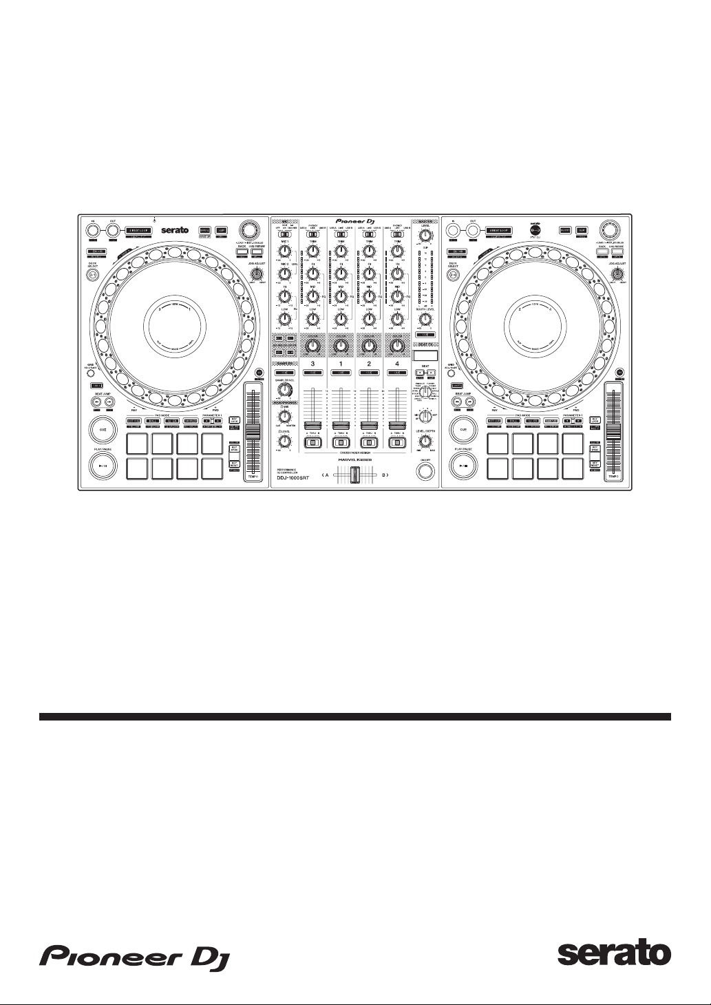
DJ Controller
DDJ-1000SRT
Operating Instructions
Page 2

How to read this manual
Thank you for choosing this Pioneer DJ product.
• Be sure to read this manual and the “Operating Instructions (Quick
Start Guide)” which are also included with this product. Both
documents include important information that you should understand
before using the unit. In particular, be sure to read the IMPORTANT
SAFETY INSTRUCTIONS.
• In this manual, the names of buttons, knobs and terminals that
appear on the product, and the names of buttons, menus, etc. in the
software on your PC/Mac are indicated within square brackets ([ ]).
(e.g. [Files], [CUE] button)
• Please note that the screens and specifications of the software, as
well as the external appearance and specifications of the hardware,
were still under development at the time this manual was created and
may differ from the final specifications.
• Please note that, depending on the operating system version, web
browser settings, etc., operation may differ from the ways shown in
this manual.
• Please note that the language on the screens of the software
described in this manual may differ from the language on your
screen.
This manual provides brief descriptions regarding the names of
parts on the unit and the connections between the unit and
peripherals.
For detailed instructions on using Serato DJ Pro software, see the
Serato DJ Pro software manual.
• You can download the Serato DJ Pro software manual from
Serato.com. For details on how to find the Serato DJ Pro
software manual, see: Downloading the Serato DJ Pro software
manual (page 6)
2
En
Page 3

Contents
How to read this manual............................................................... 2
Before you start......................................................................... 5
What’s in the box .......................................................................... 5
Acquiring the manual.................................................................... 6
Installing the software................................................................... 7
Part names and functions ......................................................15
Top panel.................................................................................... 15
Browser section .......................................................................... 16
Deck section ............................................................................... 18
Jog display section ..................................................................... 26
Mixer section............................................................................... 28
Rear panel .................................................................................. 33
Front panel.................................................................................. 36
Basic use.................................................................................. 37
Connection examples ................................................................. 38
Launching the system................................................................. 45
Quitting the system ..................................................................... 52
Advanced use.......................................................................... 53
Using 4 Beat Loop ...................................................................... 53
Using Manual Loop..................................................................... 54
Using the Performance Pads...................................................... 56
Using Pitch Play.......................................................................... 67
Using Slip.................................................................................... 69
Using Fader Start........................................................................ 74
Using effects ............................................................................... 76
Using BEAT FX........................................................................... 76
Types of BEAT FX ...................................................................... 79
En
3
Page 4

Contents
Using SOUND COLOR FX ......................................................... 89
Using a microphone.................................................................... 91
Using external inputs .................................................................. 92
Changing the settings.............................................................94
Launching Utilities mode............................................................. 94
Utilities modes ............................................................................ 95
Setting utility software............................................................... 108
Setting Crossfader Curve ......................................................... 111
Additional information.......................................................... 112
Troubleshooting........................................................................ 112
Liquid crystal display................................................................. 119
Signal flow ................................................................................ 120
Specifications............................................................................ 121
Using the unit as a controller for other DJ applications ............ 124
About trademarks and registered trademarks .......................... 131
Cautions on copyrights ............................................................. 132
4
En
Page 5

Before you start
What’s in the box
• AC adapter
• Power plug
• USB cable
• Warranty (for some regions)
• Operating Instructions (Quick Start Guide)
• Serato DJ Pro Expansion Pack Voucher
*1
Only one USB cable is supplied with the unit. If you want to use two,
use a cable that supports USB 2.0.
*2
Only products in Europe.
– For the North American region, the corresponding information is
provided on the last page of both the English and French versions
*1
*2
*3
of the “Operating Instructions (Quick Start Guide).”
*3
Please note that the Serato DJ Pro Expansion Pack Voucher can’t
be reissued. You’ll need to use the voucher code to activate the
expansion pack. Be sure to store it in a safe place.
5
En
Page 6

Before you start
Acquiring the manual
Downloading the Serato DJ Pro software manual
1 Visit the Serato website.
http://serato.com/
2Click [Serato DJ Pro] in the [Products] menu.
3Click [Download].
4Click [Manuals and downloads].
5 Click the Serato DJ Pro software manual in the language you need.
6
En
Page 7

Before you start
Installing the software
Before you install the software
The Serato DJ Pro software and driver software aren’t included with
the unit.
Access and download the software from the Pioneer DJ support page.
pioneerdj.com/support/
• You are responsible for preparing your PC/Mac, network devices,
and other elements needed to connect to the internet.
Downloading the driver software
1 Launch a web browser on your PC/Mac and visit the Pioneer DJ
website.
pioneerdj.com
• To select your language, click the flag icon in the top-right corner of the
screen.
2 Hover the cursor over [Support].
3Click [Software & firmware updates].
4Click [DDJ-1000SRT] under [DJ CONTROLLER].
5Click [Drivers].
6Click [Download link], then save the file.
7
En
Page 8
Before you start
About the Serato DJ Pro software
Serato DJ Pro is a DJ software application made by Serato Limited.
DJ performances are enabled by connecting the unit to your PC/Mac
with the software installed.
Minimum computer requirements
Supported operating systems CPU and memory required
Mac: macOS Mojave 10.14 /
macOS High Sierra 10.13 /
macOS Sierra 10.12
(latest update)
Windows: Windows® 10 /
Windows
(latest service pack)
• 32-bit operating systems not supported.
Others
USB port Your PC/Mac must have a USB 2.0 port to
Display resolution Resolution of 1280 × 720 or greater
®
8.1 / Windows® 7
connect with the unit.
Intel® processor Core™ i3, i5, i7
and i9
1.07 GHz or better
4 GB or more of RAM
Intel® processor Core™ i3, i5, i7
and i9
1.07 GHz or better
4 GB or more of RAM
Internet connection You’ll need an internet connection to
register your user account at Serato.com
and to download the software.
• For information on the latest system requirements, compatibility, and
supported operating systems of Serato DJ Pro, visit the website
below.
https://serato.com/dj/pro/downloads
En
8
Page 9

Before you start
• Be sure to use the latest version and latest service pack for your
operating system.
• Operation isn’t guaranteed on all PC/Mac models, even if the system
requirements are met.
• Depending on power-saving settings and other conditions of the PC/
Mac, the CPU and hard disk may not provide sufficient processing
capabilities. For laptops in particular, make sure the PC/Mac is in the
best condition to provide constant high-level performance when
using Serato DJ Pro (e.g. by keeping the AC power connected).
• To use the internet, you need a separate contract with an internet
service provider, which you may have to pay for.
Downloading the Serato DJ Pro software
1 Visit the Serato website.
http://serato.com/
2Click [Serato DJ Pro] under [Products].
The Serato DJ Pro download page is displayed.
• The download page is subject to change.
3Click [DOWNLOAD v*.*].
4 Create a Serato.com user account.
• If you’ve already registered an account, skip to step 6.
• If you haven’t finished registering your account, follow the steps below.
– Following the instructions on the screen, enter your email address and
create a password, then select the region where you live.
– If you check [Go backstage with Serato], you’ll receive newsletters with
the latest information on Serato Limited products.
– Once you’ve finished registering your user account, you’ll receive an
email. Check the contents of the email.
• Be careful not to forget the email address and password you used to register.
You’ll need them to update the software in future.
9
En
Page 10

Before you start
• The personal information you entered when registering your user account
may be collected, processed, and used based on the privacy policy on the
Serato website.
5 Click the link in the email you received from Serato.com.
This takes you to the Serato DJ Pro download page.
6 Log in.
Enter the email address and password you registered to log in to Serato.com.
7 Select [A laptop with a supported controller, mixer or interface]
on the download page, and click [DOWNLOAD SERATO DJ PRO]
to download the software.
Installation procedure (Mac)
Do not connect the unit to your Mac until installation is complete.
• Quit any other programs that are running on your Mac.
1 Unzip the downloaded driver software (DDJ1000SRTXXXdmg.zip).
2 Double-click [DDJ-1000SRT_M_X.X.X.dmg].
3 Double-click [DDJ-1000SRT_AudioDriver.pkg].
4 Follow the on-screen instructions to install.
5 Unzip the downloaded Serato DJ Pro software file.
6 Double-click the unzipped software file to launch the installer.
10
En
Page 11
Before you start
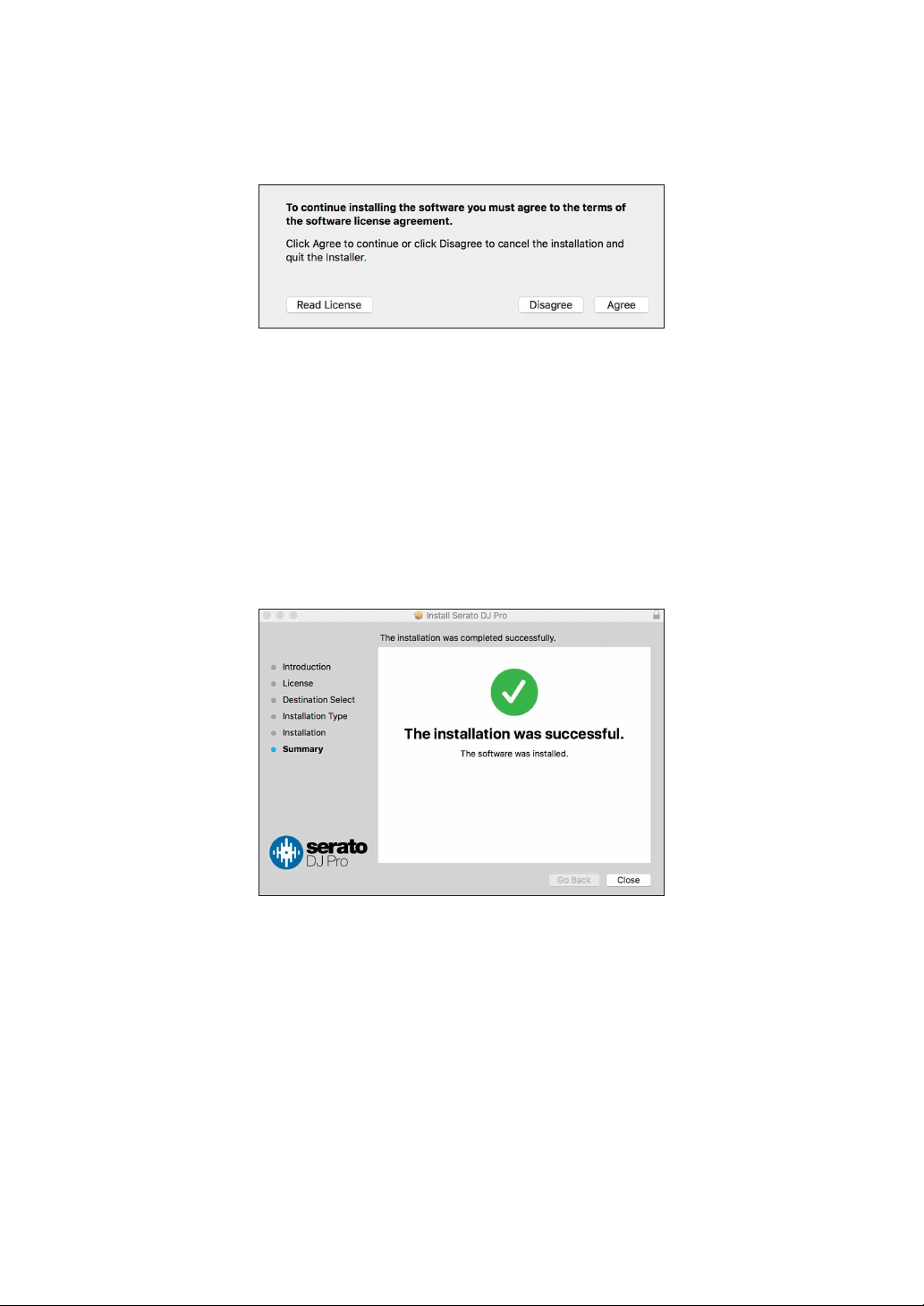
7 Read the terms of the license agreement carefully, and if you agree,
click [Agree].
• If you don’t agree to the contents of the license agreement, click [Disagree]
to cancel the installation.
8Click [Install].
9 Follow the on-screen instructions to install.
10 Click [Close] to quit the installer.
Installation procedure (Windows)
Do not connect the unit to your PC until installation is complete.
• Log in to the administrator account on your PC before starting
installation.
• Quit any other programs that are running.
1 Unzip the downloaded driver software
(DDJ1000SRTXXXXexe.zip).
En
11
Page 12
Before you start
2 Double-click [DDJ-1000SRT_X.XXX.exe].
3 Follow the on-screen instructions to install.
If [Windows Security] appears on the screen during installation, click [Install
this driver software anyway] and continue with the installation.
When the installation program is finished, a completion message appears.
After installing the driver software, install the Serato DJ Pro software.
4 Unzip the downloaded Serato DJ Pro software file.
5 Double-click the unzipped software file to launch the installer.
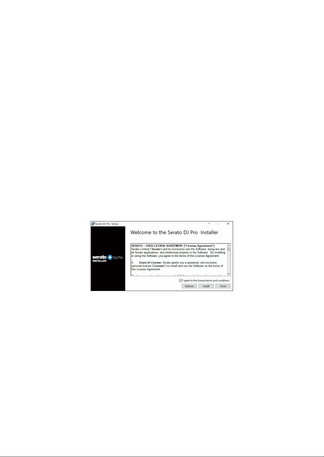
6 Read the terms of the license agreement carefully, and if you agree,
select [I agree to the license terms and conditions], then click
[Install].
• If you don’t agree to the contents of the license agreement, click [Close] to
cancel the installation.
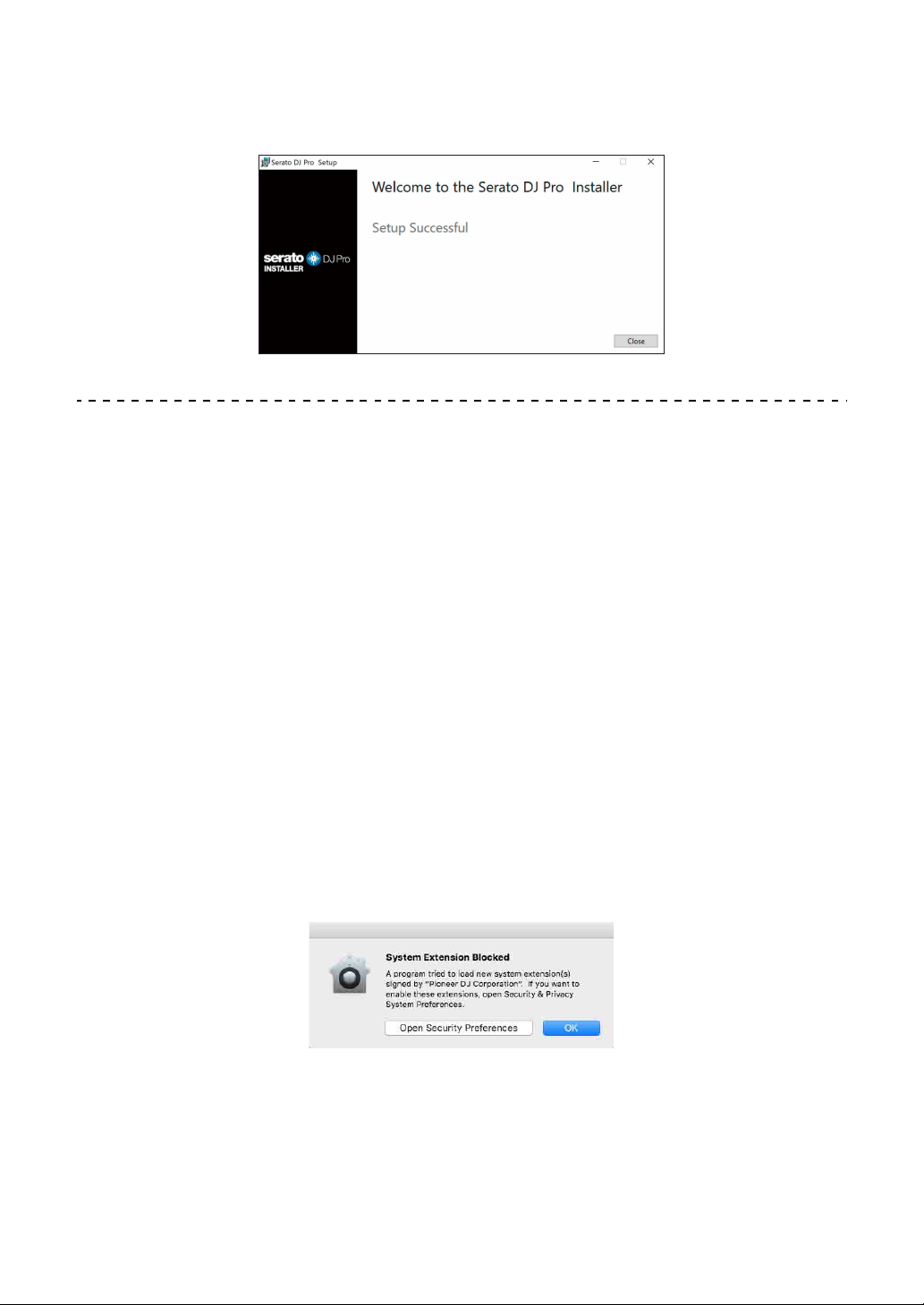
A message indicating successful installation appears when installation is
complete.
12
En
Page 13
Before you start
7Click [Close] to quit the Serato DJ Pro installer.
Installing the driver software on macOS Mojave 10.14 /
macOS High Sierra 10.13
A new security feature has been added to macOS Mojave 10.14 /
macOS High Sierra 10.13.
When installing Pioneer DJ driver software on these versions of
macOS, driver software authentication is required.
If you’re installing the driver software for the first time and you’re
using macOS Mojave 10.14 / macOS High Sierra 10.13, you need
to follow the steps below. If the driver software was installed on
macOS or OS X before you updated to macOS Mojave 10.14 /
macOS High Sierra 10.13, you don’t need to follow these steps.
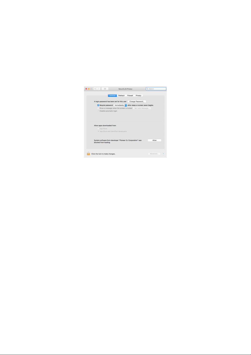
1 Install Pioneer DJ’s driver software in macOS Mojave 10.14 or
macOS High Sierra 10.13.
The following dialog box will appear during driver software installation.
2Click [Open Security Preferences].
The [Security & Privacy] dialog box is displayed.
En
13
Page 14
Before you start
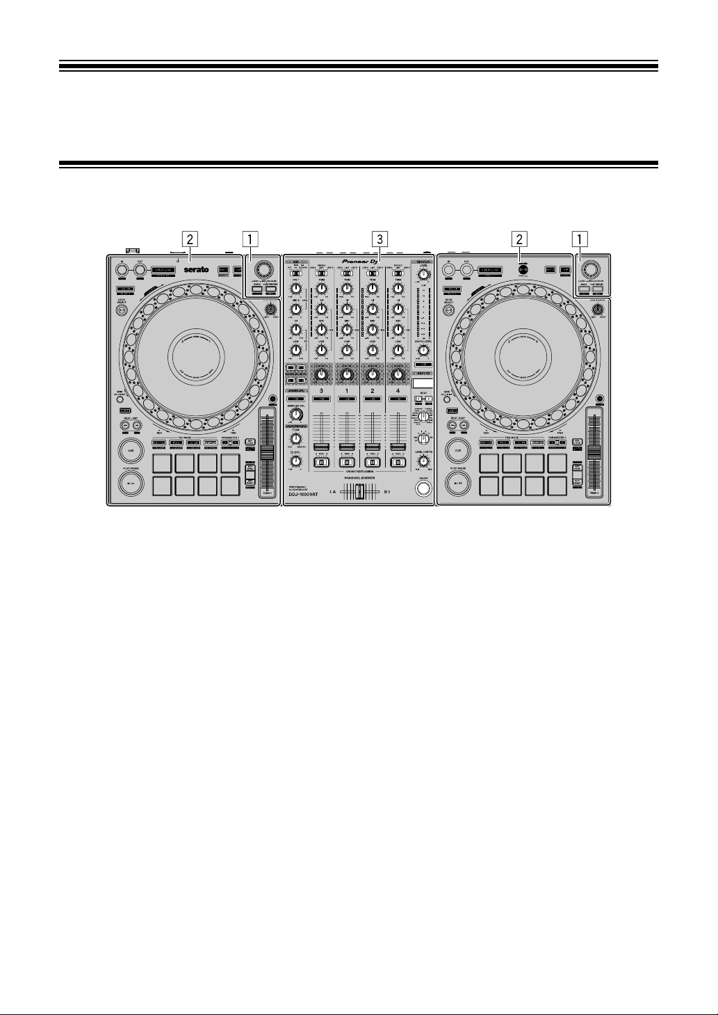
3 Check that [System software from developer “Pioneer DJ
Corporation” was blocked from loading.] appears at the bottom
of the screen.
This message will be displayed for 30 minutes after you start the installation of
the driver software.
If it is not displayed, reinstall the driver software.
4Click [Allow] at the bottom right of the screen.
5 When this unit is connected to a Mac, disconnect the USB cable
and then reconnect it again.
14
En
Page 15
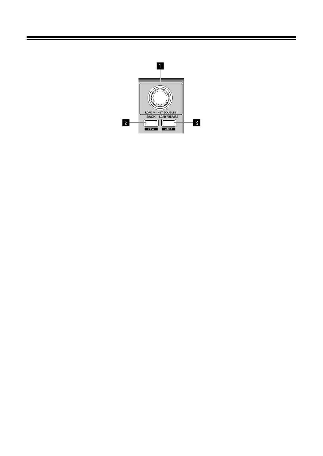
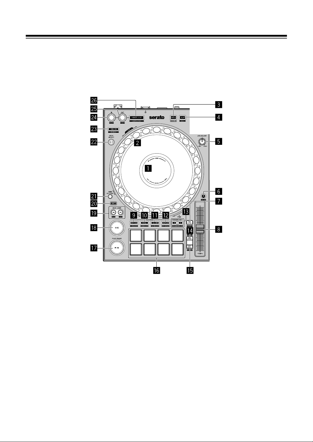
Part names and functions
Top panel
1 Browser section (page 16)
2 Deck section (page 18)
3 Mixer section (page 28)
15
En
Page 16
Part names and functions
Browser section
1 Rotary selector
Turn:
Moves the cursor up or down in the library or in the [crates] panel.
Press:
Loads the selected track onto a deck.
When the cursor is in the [crates] panel, the cursor is moved to the library.
Press twice:
Loads the track onto the deck being played from the deck not being played.
When the track is loaded, the playback position isn’t changed.
2 BACK button
Press:
Move the cursor between the library and [crates] panel each time you press
the button.
If there are sub-crates for the item currently selected in the [crates] panel,
those crates are expanded or collapsed.
When the cursor is in the [Files] panel, the cursor moves to a higher layer.
When the cursor is in the [Browse] panel, the cursor moves to the previous
category.
[SHIFT] + press:
Changes the screen layout of Serato DJ Pro.
En
16
Page 17

Part names and functions
3 LOAD PREPARE button
Press:
Loads a track onto the [Prepare] panel.
[SHIFT] + press:
Changes the panel of Serato DJ Pro.
No panel [Files] panel [Browse] panel [Prepare] panel
[History] panel No panel
17
En
Page 18
Part names and functions
Deck section
You can control four decks with the unit. There are knobs and buttons
on the left side to control decks 1 and 3, and on the right side to control
decks 2 and 4.
1 On Jog Display
Read more: Jog display section (page 26)
2 Jog wheel
Turn the top:
‘Scratches’ when VINYL mode is on.
Bends the pitch or ‘Pitch Bend’ (slows down or speeds up the track) when
VINYL mode is off.
Turn the outer section:
Bends the pitch or ‘Pitch Bend’ (slows down or speeds up the track).
En
18
Page 19

Part names and functions
[SHIFT] + turn the top:
The playback position skips in sync with the beat. (Skip mode)
• Skip mode can’t be used with tracks for which no beatgrid is set. For details
on setting beatgrids, see the Serato DJ Pro software manual.
• To use Skip mode, open the [SETUP] menu of Serato DJ Pro > [SYNC
PREFERENCES] and select [Smart Sync].
3 QUANTIZE button
Press:
Turns the Quantize function on/off.
Press (during Standby mode):
Cancels Standby mode.
• This action can only be used on the left deck.
4 SLIP button
Press:
Turns Slip mode on/off.
Read more: Using Slip (page 69)
[SHIFT] + press:
Turns VINYL mode on/off.
5 JOG ADJUST knob
Adjusts the load applied when the jog wheel is turned.
Turn the knob clockwise to increase the load, or turn the knob counter-
clockwise to decrease the load.
6 SYNC button
Press:
Automatically synchronizes the tempos (BPM) and beatgrids with a track on
one of the other decks.
[SHIFT] + press:
Cancels Sync mode.
19
En
Page 20

Part names and functions
7 KEY LOCK button
Press:
Turns the Key Lock function on/off.
When the Key Lock function is on, the key doesn’t change even when the
playing speed is changed using the [TEMPO] slider.
• The sound is digitally processed, so the sound quality decreases.
[SHIFT] + press:
Switches the range of the [TEMPO] slider each time the button is pressed
while holding the [SHIFT] button.
Switch between [±8%] [±16%] [±50%] [±8%].
Hold down for at least one second:
Sets the tempo (BPM) of the currently playing track back to its original tempo.
8 TEMPO slider
Adjusts the playing speed of the track.
9 HOT CUE mode button
Press:
Sets Hot Cue mode.
Read more: Using Hot Cues (page 56)
[SHIFT] + press:
Sets Cue Loop mode.
Read more: Using Cue Loop (page 63)
a ROLL mode button
Press:
Sets Roll mode.
[SHIFT] + press:
Sets Save Loop mode.
20
En
Page 21

Part names and functions
b SLICER mode button
Press:
Sets Slicer mode.
[SHIFT] + press:
Sets Slicer Loop mode.
• To cancel Slicer mode and Slicer Loop mode, press the [ROLL] mode
button, [SAMPLER] mode button or [HOT CUE] mode button.
c SAMPLER mode button
Press:
Sets Sampler mode.
Read more: Using the Sampler (page 62)
[SHIFT] + press:
Sets Pitch Play mode.
Read more: Using Pitch Play (page 67)
d PARAMETER, buttons
Sets the parameter for Loop Roll, Slicer, Sampler and other functions.
Read more: Using the Performance Pads (page 56)
e KEY SYNC button
Press:
Changes the key to match one of the other decks.
[SHIFT] + press:
Turns up the key.
21
En
Page 22

Part names and functions
f KEY RESET button
Press:
When this button is pressed during Key Sync, the key returns to its original key.
[KEY SYNC] and [KEY RESET] buttons are used for the Pitch ’n Time
function. To use this function, you’ll need to activate Pitch ’n Time. For more
details, read the Pitch ’n Time DJ Activation Manual under [Extra software
information] on the Pioneer DJ support page.
pioneerdj.com/support/
The key of the currently playing track of the selected deck returns to its original
key.
[SHIFT] + press:
Turns down the key.
g Performance Pads
You can use Performance Pads to trigger various features.
Read more: Using the Performance Pads (page 56)
h PLAY/PAUSE button
Press:
Plays/pauses a track.
[SHIFT] + press:
Returns to the temporary cue point and playback starts. (Stutter)
i CUE button
Press:
Sets, plays and calls up a temporary cue point.
• Press this button when the track is paused to set the temporary cue point.
• Press this button when the track is playing to return to the temporary cue
point and pause. (Back Cue)
• Press this button and hold it after the track returns to the temporary cue point
and playback will continue until you release the button. (Cue Sampler)
• When you press the [PLAY/PAUSE ] button during the Cue Sampler,
playback continues from that point.
En
22
Page 23

Part names and functions
[SHIFT] + press:
Loads the previous track from the track list. (Previous Track)
• The playback position returns to the beginning of the track.
j BEAT JUMP (1/2X), BEAT JUMP (2X) buttons
Press:
Changes the playback position by the set beat(s).
[SHIFT] + [BEAT JUMP (1/2X)]:
Halves the beat for changing the playback position.
[SHIFT] + [BEAT JUMP (2X)]:
Doubles the beat for changing the playback position.
k SHIFT button
Press another button while holding the [SHIFT] button to use a different feature
assigned to the button.
l GRID button
Turn the top of the jog wheel while holding down the [GRID] button to adjust
the interval of beatgrids.
Turn the outer section of the jog wheel while holding down the [GRID] button
to slide the beatgrid to the right or left.
m DECK SELECT button
Press:
Switches the deck to be used.
n CENSOR button
Press:
Hold down the button to play the track in the reverse direction. Normal
playback resumes when the button is released.
• Even during playback in the reverse direction, normal playback continues in
the background. When the button is released, playback resumes from the
point reached in the background.
23
En
Page 24

Part names and functions
[SHIFT] + press:
Plays the track in the reverse direction. When you press the [SHIFT] and
[CENSOR] buttons again, reverse playback is canceled, and then normal
playback resumes.
o LOOP IN button
Press:
Sets a Loop In Point.
Press this button during loop playback to finely adjust the loop in point using
the jog wheel.
[SHIFT] + press:
Halves the loop playback length.
p LOOP OUT button
Press:
Sets a Loop Out Point and starts loop playback.
Press this button during loop playback to finely adjust the Loop Out point using
the jog wheel.
[SHIFT] + press:
Doubles the loop playback length.
q 4 BEAT LOOP button
Press:
During normal playback, the auto beat loop of 4 beats is set, and then loop
playback starts.
During the loop playback, the loop playback is canceled.
24
En
Page 25

Part names and functions
[SHIFT] + press:
Switches the active or non-active status of the loop. (Loop Active)
• Even when the loop is set to active, loop playback doesn’t start if the
playback position isn’t in the loop.
• When the playback position reaches the active loop, the loop playback
starts.
• During the loop playback, the loop playback is canceled.
25
En
Page 26
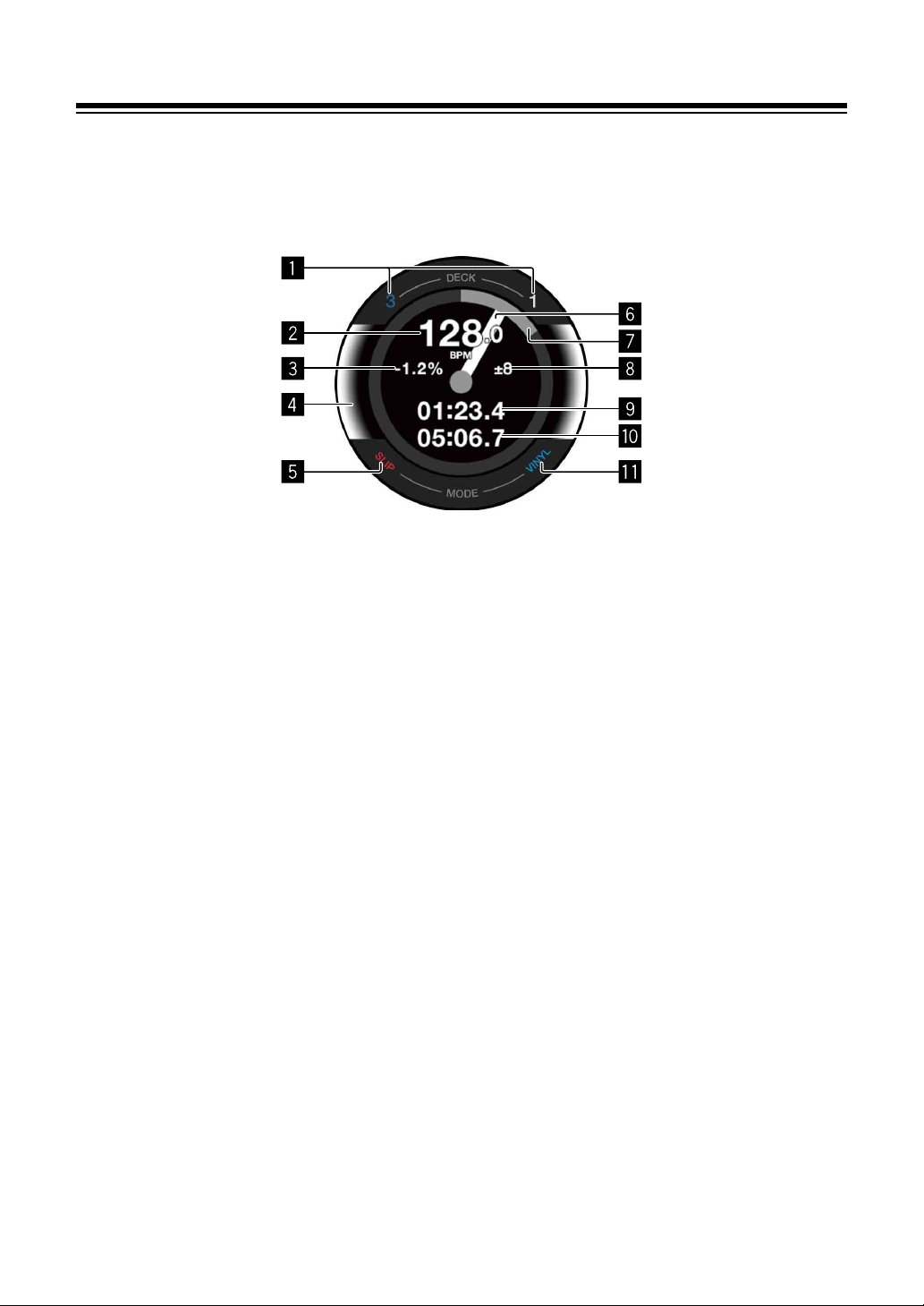
Part names and functions
Jog display section
When a track is loaded, the following information is displayed on the
jog display.
1 Deck number indicators
The number of the deck currently being used lights up.
2 BPM
Displays the current BPM.
3 Playing speed
The value changes according to the position of the [TEMPO] slider.
4 Selected deck
Indicates the selected deck by the background color.
• White: Deck 1 or 2 is selected.
• Blue: Deck 3 or 4 is selected.
5 SLIP indicator
Indicates the status of Slip mode.
• Lit up: Slip mode is on.
• Not lit: Slip mode is off.
26
En
Page 27

Part names and functions
6 Operation status
Shows the current playback position.
Rotates during playback, and stops when paused.
When the playback position reaches the set Hot Cue point, the operation status
color changes to match the Hot Cue color.
When the playback position gets closer to the Hot Cue point, the color display
area gets wider.
7 Playback position
Indicates the current playback position with the track length as one lap.
8 Playing speed adjustment range
Displays the range at which the playing speed can be adjusted.
9 Elapsed time
Displays the elapsed time.
a Remaining time
Displays the remaining time.
b VINYL indicator
Indicates the status of VINYL mode.
• Lit up: VINYL mode is on.
• Not lit: VINYL mode is off.
27
En
Page 28
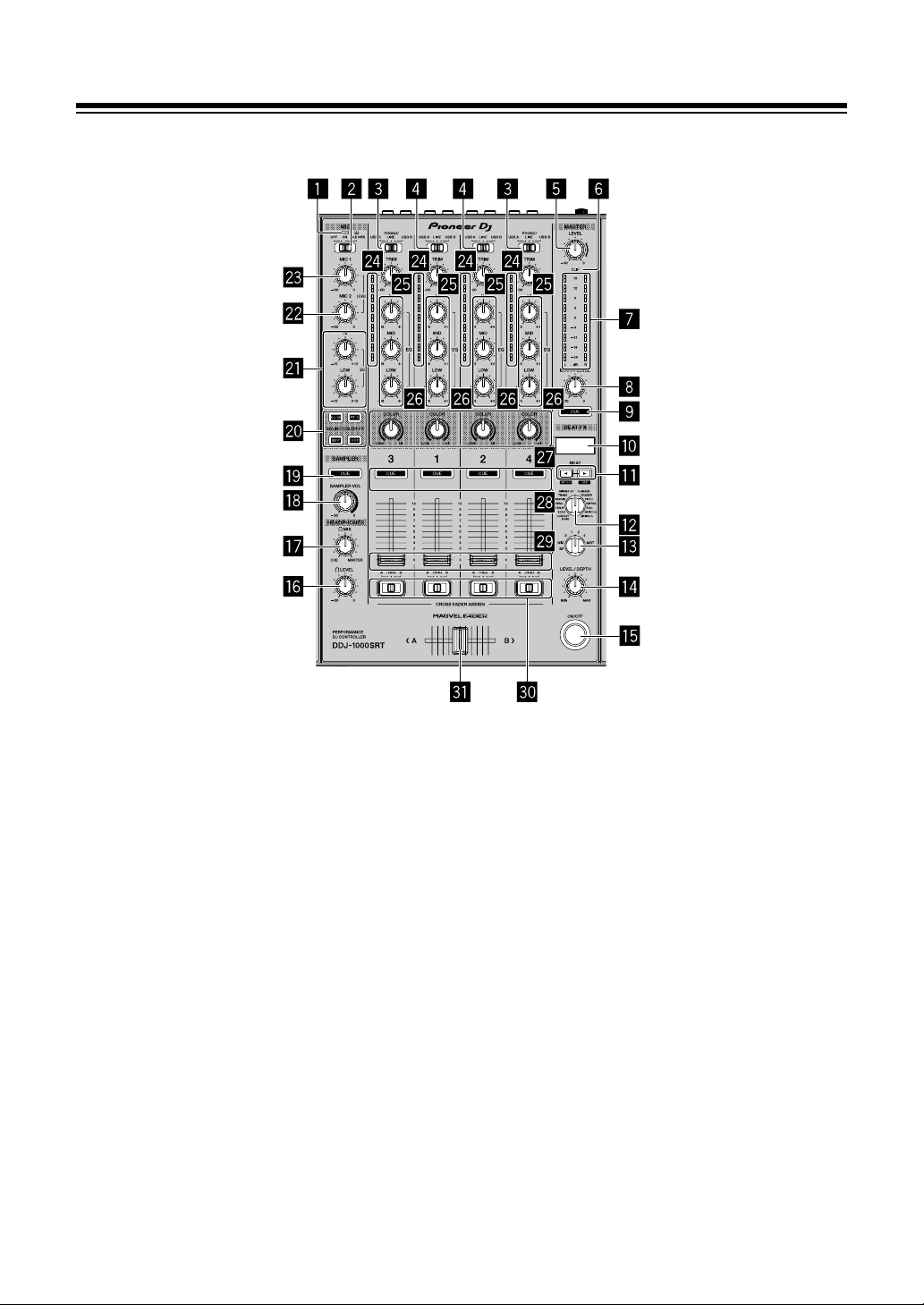
Mixer section
Part names and functions
1 MIC (microphone) indicator
Read more: Using a microphone (page 91)
2 MIC OFF, ON, TALK OVER switch
Turns the microphone on/off.
Read more: Using a microphone (page 91)
3 USB A, PHONO/LINE, USB B switches
Selects the input source of each channel from devices connected to the unit.
• [USB A]: Select to use a track loaded onto a deck.
• [PHONO/LINE]: Select to use a phono level (for MM cartridge) output device
such as a turntable connected to the [LINE/PHONO] input terminals.
Read more: Using external inputs (page 92)
• [USB B]: Select to use a track loaded onto a deck.
En
28
Page 29

Part names and functions
4 USB A, LINE, USB B switches
Selects the input source of each channel from the components connected to
the unit.
• [USB A]: Select to use a track loaded onto a deck.
•[LINE]: Select to use a line level output device (DJ player, etc.) connected to
the [LINE] input terminals.
Read more: Using external inputs (page 92)
• [USB B]: Select to use a track loaded onto a deck.
5 MASTER LEVEL knob
Adjusts the volume of the master output sound.
6 CLIP indicator
Flashes when the output level is too high.
• Slow flashing: Occurs just before the distortion of sound begins.
• Fast flashing: The sound is distorted.
7 Master level indicator
Indicates the volume of the master output sound.
8 BOOTH LEVEL knob
Adjusts the volume of the [BOOTH] output terminal sound.
9 MASTER CUE button
Plays the master sound through your headphones.
a BEAT FX display
Displays an effect name, BPM, effect parameter, etc.
b BEAT , buttons
Press:
Increases or decreases the effect timing.
[SHIFT] + [BEAT ]:
Sets to automatically enter BPM by measuring from the input sound signal.
En
29
Page 30

Part names and functions
[SHIFT] + [BEAT ]:
Sets to manually enter BPM.
c BEAT FX SELECT knob
Changes the effect type of Beat FX.
d BEAT FX CH SELECT knob
Changes the channel to which you want to add Beat FX.
e BEAT FX LEVEL/DEPTH knob
Adjusts the parameter of Beat FX.
f BEAT FX ON/OFF button
Press:
Turns Beat FX on/off.
g HEADPHONES LEVEL knob
Adjusts the volume of the headphones sound.
h HEADPHONES MIX knob
Adjusts the balance of monitor sound level between the master channel and
the channel for which the headphones [CUE] button is pressed.
i SAMPLER VOL knob
Adjusts the volume of the sampler sound.
j SAMPLER CUE button
Outputs the sampler sound from the headphones.
• Before using this button, set [Sampler Player Output Select] to [A] on
Serato DJ Pro.
k SOUND COLOR FX SELECT buttons
Turns Sound Color FX on/off.
Read more: Using SOUND COLOR FX (page 89)
l MIC EQ (HI, LOW) knobs
Adjusts the sound quality of [MIC 1] and [MIC 2] channels.
En
30
Page 31

Part names and functions
m MIC2 LEVEL knob
Adjusts the volume of the [MIC 2] channel sound.
n MIC1 LEVEL knob
Adjusts the volume of the [MIC 1] channel sound.
o Channel level indicators
Indicates the volume of the respective channel’s sound before passing through
the channel faders.
p TRIM knobs
Adjusts the volume of each channel’s sound.
q EQ (HI, MID, LOW) knobs
Boosts or reduces the relevant frequency for the selected channel.
r COLOR knobs
Changes the parameter of Sound Color FX for each channel.
s Headphones CUE buttons
Press:
Plays the sound of the relevant channel through your headphones.
[SHIFT] + press:
Hold the [SHIFT] button and tap the button to set the tempo of the respective
deck in time with your tapping. (Tap feature)
t Channel faders
Adjusts the volume of each channel’s sound.
u CROSSFADER ASSIGN switches
Assigns the channel output to the crossfader.
[A]: Assigns output to [A] (left) of the crossfader.
[B]: Assigns output to [B] (right) of the crossfader.
[THRU]: Select this when you don’t want to use the crossfader. (The signals
don’t pass through the crossfader.)
31
En
Page 32

Part names and functions
v Crossfader
The sound assigned with the crossfader assign switch is output.
Don’t forcibly pull out the channel fader and crossfader knobs. These
knobs are hard to pull out and may be broken if forcibly pulled out.
32
En
Page 33

Part names and functions
Rear panel
1 Kensington Security Slot
Connects a cable lock for security.
2 MASTER 1 output terminals
Connects a powered speaker, a power amplifier, etc.
• Compatible with XLR connector type balanced outputs.
Be sure to use these terminals as balanced outputs.
• Be careful not to accidentally insert the power cord plug of another unit
or device into any of these terminals.
• Do not connect devices capable of supplying phantom power to these
terminals.
3 MASTER 2 output terminals
Connects a powered speaker, a power amplifier, etc.
• Compatible with RCA pin-jack type unbalanced outputs.
4 BOOTH output terminals
Outputs for a booth monitor.
• Compatible with TRS connector type balanced outputs.
Be sure to use these as balanced outputs.
• Outputs the master channel sound from the [BOOTH] output terminals
regardless of the volume of the master channel sound.
The volume can be adjusted using the [BOOTH LEVEL] knob.
5 SIGNAL GND terminal
Connects the ground wire of a turntable to reduce noise that occurs when a
turntable is connected.
33
En
Page 34

Part names and functions
6 LINE/PHONO switch
Selects the input source for each channel from the devices connected to the
unit.
•[LINE]: Used when a line level output device (DJ player, etc.) is connected
to the [LINE/PHONO] input terminals.
• [PHONO]: Used when a phono level (for MM cartridges) output device
(turntable, etc.) is connected to the [LINE/PHONO] input terminals.
7 LINE/PHONO input terminals
Connects a phono level (for MM cartridges) output device (turntable, etc.) or a
line level output device (DJ player, etc.). You can switch the input source
depending on the connected device using the [LINE/PHONO] switch on the
rear panel of the unit.
• Set the [USB A, PHONO/LINE, USB B] switch on the top of the unit to
[PHONO/LINE] beforehand.
8 LINE input terminals
Connects a DJ player or other line level device.
• Set the [USB A, LINE, USB B] switch on the top of the unit to [LINE]
beforehand.
9 USB port (USB B)
Connects a PC/Mac.
• Connect this unit directly to your PC/Mac using the supplied USB cable or
one that supports USB 2.0.
• A USB hub can’t be used.
a USB port (USB A)
Connects a PC/Mac.
• Connect this unit directly to your PC/Mac using the supplied USB cable or
one that supports USB 2.0.
• A USB hub can’t be used.
b MIC2 input terminal
Connects a microphone.
• Only phone plugs (Ø 6.3 mm) can be used.
En
34
Page 35

Part names and functions
c MIC1 input terminal
Connects a microphone.
• Either an XLR connector or a phone plug (Ø 6.3 mm) can be used.
d switch
Turns the power on or standby the unit.
e DC IN terminal
Connects a power outlet using the supplied AC adapter (using the supplied
power cord).
• Connect the AC adapter after all connections are completed.
• Use the supplied AC adapter.
f Cord hook
Hook for the AC adapter power cord.
• If the AC adapter is disconnected during playback, the sound will be
interrupted.
35
En
Page 36

Part names and functions
Front panel
1 PHONES output terminals
Connects your headphones.
Stereo phone plugs (ø 6.3 mm) and stereo mini phone plugs (ø 3.5 mm) can
be used.
36
En
Page 37

Basic use
• Only connect the power cord to a power outlet after you’ve made all
other connections.
Turn off the unit and disconnect the power cord from the outlet before
connecting different devices or changing connections.
Refer to the operating instructions for any devices you want to
connect.
• Be sure to use the supplied power cord and AC adapter.
• Be sure to use the supplied USB cable or one that supports USB 2.0.
• Do not use a USB hub.
37
En
Page 38

Basic use
(1) (2) (3) (4)
(8) (9) (10) (11) (12) (13)
(7)
(6)
(5)
Connection examples
Connecting input terminals
Rear panel
(1) Turntable*
(4) Portable audio device, (5) AC adapter (supplied),
(6) Power cord (supplied), (7) To power outlet,
(8) Portable audio device, (9) Multi player, (10) Turntable*
(11) Multi player*
1
, (2) Multi player*2, (3) Multi player,
2
, (12) PC/Mac, (13) Microphone
1
,
*1
When connecting a turntable, set the [LINE/PHONO] switch beside
the terminals to [PHONO].
*2
When connecting a multi player, set the [LINE/PHONO] switch
beside the terminals to [LINE].
En
38
Page 39

Basic use
Cord hook
Hook the AC adapter’s power cord onto the cord hook.
Fasten the AC adapter’s power cord in place by hooking it onto the
cord hook. This prevents the power cord from being accidentally pulled
and the plug from being disconnected from the terminal.
• Do not bend the base of the AC adapter power cord when fastening
it. If used continuously under these conditions, the power cord may
be damaged, resulting in faulty contact.
• The sound will be interrupted if the AC adapter is disconnected
during playback.
39
En
Page 40

Basic use
(1)
(2) (3)
Connecting output terminals
Rear panel
(1) Devices, amplifier, powered speakers, etc.,
(2) Power amplifier, powered speakers, etc.,
(3) Power amplifier (for booth monitor), powered speakers, etc.
En
40
Page 41

Basic use
Front panel
(1) Headphones
(1)
1 Be sure to use the [MASTER 1] output terminals for a balanced
output.
If these terminals are connected to an unbalanced input (such as RCA) using
an XLR to RCA converter cable (or a converter adapter), etc., sound quality
may decrease or noise may occur.
To connect to an unbalanced input (such as RCA), use the [MASTER 2] output
terminals.
2 Be careful not to accidentally insert the power cord plug of another
unit or device into a [MASTER 1] output terminal.
Do not connect devices capable of supplying phantom power to the
[MASTER 1] output terminals.
3 Be sure to use the [BOOTH] output terminals for a balanced output.
If these terminals are connected to an unbalanced input (such as an RCA or
TS terminal) using a TRS to RCA converter cable (or a converter adapter), TS
cable, etc., sound quality may decrease or noise may occur.
41
En
Page 42

Basic use
Connecting
1 Connect headphones to one of the [PHONES] output terminals
.
2 Connect powered speakers, a power amplifier, devices, etc. to the
[MASTER 1] or [MASTER 2] output terminals.
• To output the sound from the [BOOTH] output terminals, connect speakers
or other devices to the [BOOTH] output terminals.
En
42
Page 43

3 Connect the unit to your PC/Mac via a USB cable.
4 Turn on your PC/Mac.
Basic use
5 Connect the AC adapter.
43
En
Page 44

Basic use
6 Press the [] switch on this unit’s rear panel to turn this unit on.
• For Windows users
The preparing device message may appear the first time you connect the
unit to your PC or when you connect it to a different USB port. Wait until the
ready-to-use message appears.
7 Turn on the devices connected to the output terminals (powered
speakers, power amplifier, etc.).
• When a microphone, DJ player or other external device is connected to input
terminals, turn on that device too.
44
En
Page 45

Basic use
Launching the system
Launching Serato DJ Pro
This manual mainly focuses on explaining the hardware functions of
the unit. For detailed instructions on using the Serato DJ Pro software,
see the Serato DJ Pro software manual.
For Mac
In Finder, open the [Applications] folder, then click the [Serato DJ
Pro] icon.
For Windows 10
From the [Start] menu, click [Serato] > [Serato DJ Pro] icon.
For Windows 8.1
From [Apps view], click the [Serato DJ Pro] icon.
For Windows 7
In the Windows [Start] menu, click [All Programs] > [Serato] >
[Serato DJ Pro].
45
En
Page 46

Basic use
The screen directly after the Serato DJ Pro software is launched
• The [BUY/ACTIVATE] icon may appear on the right side of the
screen when you launch Serato DJ Pro for the first time. However,
you don’t need a license to use the DDJ-1000SRT. You can buy
expansion packs such as DVS and use them as additional options.
The screen when tracks are loaded onto decks in the Serato DJ
Pro software
Click [Library] in the top-left corner of the screen, then select
[Vertical] or [Horizontal] from the pull-down menu to change the
Serato DJ Pro screen.
A Deck section
The track information (track name, artist name, BPM, etc.), the overall
waveform and other information of the loaded track are displayed.
B Waveform display
The waveform of the loaded track is displayed.
En
46
Page 47

Basic use
a
b
C Browser section
Tracks in the library, or crates containing multiple tracks, are displayed.
Importing music files (tracks)
• There are various ways to import tracks into Serato DJ Pro. For
details, see the Serato DJ Pro manual.
• If you’re already using Serato Limited’s DJ software (e.g. Scratch
Live, ITCH, Serato DJ Intro, or Serato DJ Lite) and you’ve already
created track libraries, you can use these libraries.
• If you’re using Serato DJ Lite and you’ve already created track
libraries, you may need to reanalyze tracks.
The typical way to import music files (tracks) is as follows.
1Click the [Files] key in the Serato DJ Pro screen to open the [Files]
panel.
The contents of your PC/Mac or the hard drive/device connected to the PC/
Mac are displayed in the [Files] panel.
2 Click the folder containing the tracks you want to add to your library.
3 Drag and drop the selected folder to the crates panel.
A crate is created and the tracks are added to your library.
a [Files] panel
b Crates panel
En
47
Page 48

Basic use
a
b
Loading a track onto a deck
The following explains how to load a track onto deck [1] as an example.
1 Rotary selector
2 BACK button
1 Press the [BACK] button on the unit, move the cursor to the crates
panel, then turn the rotary selector to select the crate, etc.
2 Press the rotary selector, move the cursor to the library, then turn
the rotary selector to select the track you want to load.
a Library
b Crates panel
3 Press the rotary selector.
The track loads onto deck 1.
En
48
Page 49

Basic use
Playing tracks
The following describes how to play the track on deck 1 (left) as an
example.
1 USB A, LINE, USB B switch
2 TRIM knob
3 EQ (HI, MID, LOW) knobs
4 COLOR knob
5 Headphones CUE button
6 Channel fader
7 HEADPHONES MIX knob
8 HEADPHONES LEVEL knob
9 CROSSFADER ASSIGN switch
49
En
Page 50

Basic use
a Crossfader
b MASTER LEVEL knob
c BOOTH LEVEL knob
d MASTER CUE button
1 Set the positions of the knobs, etc. as shown below.
• [USB A, LINE, USB B] switch: [USB A]
•[TRIM] knob: Turned fully counterclockwise
• [EQ (HI, MID, LOW)] knobs: Center
• [COLOR] knob: Center
• Channel fader: Bottom position
• [MASTER LEVEL] knob: Turned fully counterclockwise
• Crossfader: Center
• [CROSSFADER ASSIGN] switch: [THRU]
2 Press the [PLAY/PAUSE ] button to play the track.
3 Turn the [TRIM] knob.
Adjust the [TRIM] knob so the channel level indicator lights up orange at the
loudest part of the track.
4 Move the channel fader away from you.
50
En
Page 51

Basic use
5 Turn the [MASTER LEVEL] knob to adjust the volume level of the
speakers.
Adjust the sound level output from the [MASTER] output terminals to an
appropriate level.
• If you’re outputting sound from the speaker of your PC/Mac, adjust the
speaker volume on the PC/Mac instead of using the [MASTER LEVEL]
knob.
Monitoring with headphones
1 Set the positions of knobs, etc. as shown below.
• [HEADPHONES MIX] knob: Center
• [HEADPHONES LEVEL] knob: Turned fully counterclockwise
2 Press the headphones [CUE] button for channel 1.
3 Turn the [HEADPHONES LEVEL] knob.
Adjust the headphones volume to a level you’re happy with.
Note
This unit and the Serato DJ Pro software include a variety of features
enabling characteristic DJ performances. For details on the respective
features, read this manual and the Serato DJ Pro software manual.
• The Serato DJ Pro software manual can be downloaded from Serato.com. For
details, see: Downloading the Serato DJ Pro software manual (page 6).
51
En
Page 52

Basic use
Quitting the system
1 Quit Serato DJ Pro.
When you close the software, a question appears on your PC/Mac screen
asking for confirmation that you want to close it. Click [Yes] to close.
2 Press the [] switch on the unit’s rear panel to set the unit to
standby mode.
3 Disconnect the USB cable from your PC/Mac.
52
En
Page 53

Advanced use
Using 4 Beat Loop
During playback, press the [4 BEAT LOOP] button.
Loop playback starts with 4 beats from the point where you press the
button.
• When the Quantize function is turned on, you might notice a slight
delay as the loop synchronizes to the beat.
Canceling loop playback
Press the [4 BEAT LOOP] button again.
When the Loop Out point is reached, the rest of the track continues to
play without returning to the Loop In point.
53
En
Page 54

Advanced use
Using Manual Loop
You can choose the section you want to loop.
• When the Quantize function is turned on, you might notice a slight
delay as the loop synchronizes to the beat.
1 Press the [LOOP IN] button at the point you want to start looping
(the Loop In Point) during playback.
2 Press the [LOOP OUT] button at the point you want the loop to end
(the Loop Out Point).
The loop playback starts.
Cutting the loop
Press the [LOOP IN] button while holding the [SHIFT] button.
Each time you press the button, the loop cuts in half.
• The loop length can be cut in half even during 4 beat loop playback.
Extending the loop
Press the [LOOP OUT] button while holding the [SHIFT] button.
Each time you press the button, the loop doubles in length.
• The loop length can be doubled even during 4 beat loop playback.
Canceling a loop
Press the [4 BEAT LOOP] button.
The rest of the track continues to play without returning to the Loop In
point.
54
En
Page 55

Advanced use
Changing the Loop In point
Press the [LOOP IN] button, and turn the jog wheel.
The Loop In point is changed.
Changing the Loop Out point
Press the [LOOP OUT] button, and turn the jog wheel.
The Loop Out point is changed.
55
En
Page 56

Advanced use
Hot Cue 1Hot Cue 2Hot Cue 3Hot Cue
4
Hot Cue 5Hot Cue 6Hot Cue 7Hot Cue
8
Using the Performance Pads
You can switch the functions using the respective pad mode buttons
(the [HOT CUE] mode button, [ROLL] mode button, [SLICER] mode
button and [SAMPLER] mode button).
Using Hot Cues
You can start playback instantly from the position where a Hot Cue is
set.
• Up to 8 Hot Cue points can be set and saved for each track.
1 Press the [HOT CUE] mode button.
The unit enters Hot Cue mode.
2 If the track is playing or paused, press a Performance Pad to set the
Hot Cue point.
The Hot Cue points are set to Performance Pads as follows:
3 Press a Performance Pad you’ve set a Hot Cue for.
Playback starts from the Hot Cue point.
• You can clear Hot Cue points by pressing a Performance Pad while holding
the [SHIFT] button.
56
En
Page 57

Advanced use
4 beats 8 beats 16 beats2 beats
Using Roll
When you press a Performance Pad, a loop with the number of beats
assigned to the pad is set and the loop plays until you release the pad.
During loop roll playback, normal playback with the original rhythm
continues in the background. When a loop roll is canceled, playback
resumes from the position reached in the background.
1 Press the [ROLL] mode button.
The unit enters Roll mode.
2 Press the [PARAMETER] or [PARAMETER] button.
The loop roll beats assigned to Performance Pad 1 through 4 switch each time
you press a button.
For example, when you set a pad to “2 to 16 beats,” the pad’s setting is as
shown below.
The range of beats set for the loop roll is displayed on the PC/Mac screen.
3 Press and hold down one of the Performance Pads.
A loop roll with the number of beats in the settings assigned to that pad is
played.
Playback continues in the background during loop roll playback.
• While holding the [SHIFT] button, press the [LOOP IN] or [LOOP OUT]
button during loop roll to change the number of beats for the current playback
loop roll.
En
57
Page 58

Advanced use
2X jump
beat
Beat
Jump to
the left
Beat
Jump to
the right
1/2X
jump
beat
4 Release the Performance Pad.
The loop roll is canceled, and playback resumes from the position reached in
the background.
Using Beat Jump
Use Performance Pad 5 through 8 during Roll mode to jump the
playback position instantly without changing the original rhythm.
• Performance Pad 6 or 7:
The jump beat is halved or doubled.
The range of jump beats set is displayed on the PC/Mac screen.
• Performance Pad 5 or 8:
The playback position is jumped to the left or right with the jump beats
set.
58
En
Page 59

Advanced use
Using Slicer
The specified range is divided into 8 equal sections, and these 8 sliced
sections are assigned to the respective Performance Pads. While you
hold down a Performance Pad, the sound for the section assigned to
that pad is played in a loop.
While playing a loop of the pad’s sound, normal playback with the
original rhythm continues in the background. When you release the
Performance Pad and loop playback ends, playback resumes from the
position reached at that point.
• The Slicer function can't be used with tracks for which no beatgrid is
set. For details on setting beatgrids, read the Serato DJ Pro software
manual.
1 Press the [SLICER] mode button.
The unit enters Slicer mode.
• Press the [SLICER] mode button while holding the [SHIFT] button to enter
Slicer Loop mode.
Read more: About Slicer mode and Slicer Loop mode (page 61)
2 Press the [PARAMETER] or [PARAMETER] button while
holding the [SHIFT] button.
Set the domain for the Slicer function. The value set for the domain switches
each time you press one of the buttons while holding the [SHIFT] button.
The domain can be set to one of 6 settings: 2 beats, 4 beats, 8 beats, 16 beats,
32 beats or 64 beats.
59
En
Page 60

Advanced use
Section
1
DOMAIN
Sliced section 1 to 8
Section
5
Section
2
Section
6
Section
3
Section
7
Section
4
Section
8
The domain is divided equally into 8 sliced sections, which are assigned to
each pad as displayed below.
1234 56 7 8
3 Press the [PARAMETER] or [PARAMETER] button.
Set the quantization for the Slicer function. The value set for the quantization
switches each time you press one of the buttons.
The quantization can be set to one of 4 settings: 1/8, 1/4, 1/2 and 1.
With the quantization setting, you can change the length of the loop which is
played while holding the pad. For example, when the quantization is set to 1,
the entire section assigned to the pad is played in a loop, and when the
quantization is set to 1/2, only the first half of the section assigned to the pad
is played in a loop.
4 Press and hold down a Performance Pad.
While holding down the pad, playback continues in a loop.
• The length of the loop differs depending on the quantization setting.
When you release the pad, playback resumes from the position reached in the
background.
60
En
Page 61

Advanced use
12345678112
2
…
345678
About Slicer mode and Slicer Loop mode
Slicer mode
When the playback position advances to the end of the range that has
been sliced into 8 equal sections, the range shown on the display
switches to the next 8 sliced sections, and these sliced sections are
assigned to the respective pads, replacing the previously assigned
sections.
Slicer Loop mode
When the playback position advances to the end of the range that has
been sliced into 8 equal sections, the playback position returns to the
beginning of the range.
12345678
En
61
Page 62

Advanced use
Slot 1 Slot 2 Slot 3 Slot 4
Slot 5 Slot 6 Slot 7 Slot 8
Using the Sampler
You can use the Performance Pads to play tracks or sounds assigned
to the Sampler slots.
1 Open the [SAMPLER] panel.
2 Press the [SAMPLER] mode button.
The unit enters Sampler mode.
3 Press the [PARAMETER] or [PARAMETER] button.
Change the Sampler bank. The sampler has 4 banks, A, B, C and D, and each
bank has 8 slots.
4 Drag and drop tracks to load them onto the [SAMPLER] panel’s
slots.
The sampler settings and loaded tracks are saved.
5 Press a Performance Pad.
The track or sound assigned to the relevant slot is played.
• Playback method differs depending on the Serato DJ Pro’s Sampler mode.
For details, read the Serato DJ Pro software manual.
• When you press a Performance Pad while holding the [SHIFT] button, the
sound of the slot that is currently playing stops.
En
62
Page 63

Advanced use
Loop 1 Loop 2 Loop 3 Loop 4
Loop 5 Loop 6 Loop 7 Loop 8
Using Cue Loop
1 Press the [HOT CUE] mode button while holding the [SHIFT]
button.
The unit enters Cue Loop mode.
2 Press a Performance Pad during playback.
The Loop In point is set on the Hot Cue slot and loop playback starts.
• The loop length depends on the beat number setting of Auto Loop.
The Loop In point is assigned to Performance Pads as follows.
The length of the loop at this time is the number of beats set for auto looping.
The Loop In points a re assigned to the pads a s shown below.
• With the Cue Loop function, the Hot Cue point is used as the Loop In point.
If you press a Performance Pad at which a Hot Cue point is already set, a
loop starts from that Hot Cue point.
Cutting the loop
Press the [PARAMETER] button during loop playback.
Each time you press the button, the loop cuts in half.
• Press the [LOOP IN] button while holding the [SHIFT] button to
obtain the same effect.
Extending the loop
Press the [PARAMETER] button during loop playback.
Each time you press the button, the loop doubles in length.
• Press the [LOOP OUT] button while holding the [SHIFT] button to
obtain the same effect.
En
63
Page 64

Advanced use
Returning to the Loop In point
Press the same Performance Pad while holding the [SHIFT]
button.
The playback position returns to the set Loop In point and loop
playback continues.
Canceling a loop
Press the same Performance Pad again.
The rest of the track continues to play without returning to the Loop In
point.
64
En
Page 65

Advanced use
Slot 1 Slot 2 Slot 3 Slot 4
Slot 5 Slot 6 Slot 7 Slot 8
Using Saved Loops
You can save a loop in a loop slot of Serato DJ Pro and call up the
saved loop.
1 Press the [ROLL] mode button while holding the [SHIFT] button.
The unit enters Saved Loop mode.
2 Press a Performance Pad during loop playback.
The loop is assigned to the loop slot of Serato DJ Pro.
3 Press a Performance Pad while holding the [SHIFT] button.
The playback position returns to the set Loop In point and loop playback
continues.
Cutting the loop
Press the [PARAMETER] button during loop playback.
Each time you press the button, the loop cuts in half.
Extending the loop
Press the [PARAMETER] button during loop playback.
Each time you press the button, the loop doubles in length.
En
65
Page 66

Advanced use
Returning to the Loop In point
Press the same Performance Pad while holding the [SHIFT]
button.
The playback position returns to the set Loop In point and loop
playback continues.
Canceling a loop
Press the same Performance Pad again.
The rest of the track continues to play without returning to the Loop In
point.
66
En
Page 67

Advanced use
+4 +5 +6 +7
0+1+2+3
0+1+2+3
-4 -3 -2 -1
Using Pitch Play
To use this function, activation for the Pitch ’n Time function is required.
For details, see the Pitch 'n Time DJ Activation Manual in [Extra
software information] on the Pioneer DJ support page.
pioneerdj.com/support/
1 Press the [SAMPLER] mode button while holding the [SHIFT]
button.
The unit enters Pitch Play mode.
2 Press a Performance Pad while holding the [SHIFT] button to select
a set Hot Cue point.
3 Press the Performance Pad.
To select the pitch range to Up range, Middle range or Down range, press the
[PARAMETER] button or [PARAMETER] button.
With the pitch set on the pad you pressed, playback starts from the Hot Cue
point selected in step 2.
Up range
Middle range
En
67
Page 68

Down range
-3 -2 -1 0
-7 -6 -5 -4
Advanced use
En
68
Page 69

Advanced use
Using Slip
When Slip mode is on, normal playback is continued while maintaining
the original rhythm in the background during ‘Scratch’ play, loop
playback or Hot Cue playback. When ‘Scratch’ play, loop playback or
Hot Cue playback is canceled, normal playback resumes from the
position reached at that point. Various performances are possible
without breaking the rhythm.
• For the default setting, the [SLIP] button lights up when Slip mode is
on, and flashes while playback continues in the background.
Slip Hot Cue
1 Press the [HOT CUE] mode button.
The unit enters Hot Cue mode.
2 Press a Performance Pad to set a Hot Cue.
3 Press the [SLIP] button.
The unit enters Slip mode.
4 Press and hold down a Performance Pad during playback.
Playback starts from the position where the Hot Cue is set. Playback continues
while holding that pad.
Normal playback continues in the background during Hot Cue playback.
5 Release the Performance Pad.
Playback starts from the position reached in the background.
• To cancel Slip mode, press the [SLIP] button again.
69
En
Page 70

Advanced use
Slip Scratch Play
1 Make sure VINYL mode is on.
Check that the [VINYL] indicator on the jog display lights up.
2 For ‘Scratch’ play, operate the top of the jog wheel during playback.
Normal playback continues in the background during ‘Scratch’ play.
3 Release the top of the jog wheel.
Playback starts from the position reached in the background.
• To cancel Slip mode, press the [SLIP] button again.
To check if the VINYL mode is on or off
By default, VINYL mode is on, so you can ‘Scratch’. You can check the
current status with the lighting status of the [VINYL] indicator on the jog
display.
To turn VINYL mode on/off, press the [SLIP] button while holding the
[SHIFT] button.
70
En
Page 71

Advanced use
Slip Braking
1 Adjust the [BRAKING] - [Stop Time] setting in the [DJ Preference]
tab of the [SETUP] menu.
For the [BRAKING] setting, you can adjust the speed from the playback of the
track until it stops.
When using the Slip Braking, adjust the [Stop Time] knob of [BRAKING] to
around 9 o’clock to set it to stop slowly.
2 Press the [SLIP] button.
The unit enters Slip mode.
3 Press the [PLAY/PAUSE ] button during playback.
Playback stops slowly. Normal playback continues in the background while
slowly stopping.
4 Press the [PLAY/PAUSE ] button again.
Playback starts from the position reached in the background.
• To cancel Slip mode, press the [SLIP] button again.
71
En
Page 72

Advanced use
Slip Auto Loop
1 Press the [SLIP] button.
The unit enters Slip mode.
2 Press the [4 BEAT LOOP] button.
A loop with 4 beats is set at the position where you pressed the button, and
loop playback starts.
Normal playback continues in the background during loop playback.
3 Press the [4 BEAT LOOP] button again.
The loop is canceled and playback starts from the position reached in the
background.
• To cancel Slip mode, press the [SLIP] button again.
72
En
Page 73

Advanced use
Slip Manual Loop
Creating a loop in Slip mode
1 Press the [SLIP] button.
The unit enters Slip mode.
2 Press the [LOOP IN] button, then press the [LOOP OUT] button.
Loop playback starts.
Normal playback continues in the background during loop playback.
3 Press the [4 BEAT LOOP] button.
The loop is canceled and playback starts from the position reached in the
background.
• To cancel Slip mode, press the [SLIP] button again.
73
En
Page 74

Advanced use
Using Fader Start
Using Channel Fader Start
1 Set the cue point.
Pause the track at the position you want to start playback from, then press the
[CUE] button on that deck.
• You can also set the cue point by moving the channel fader from the top to
the bottom while holding the [SHIFT] button during a pause.
2 While holding the [SHIFT] button, move the channel fader from the
bottom to the top.
Playback starts from the cue point.
• If you move the channel fader back to the bottom while holding the [SHIFT]
button during playback, the track instantly jumps back to the cue point and
playback pauses. (Back Cue)
When no cue point is set, playback starts from the beginning of the track.
When you move the channel fader from the top to the bottom and hold the
[SHIFT] button while triggering a cue, playback of the track starts from the set
cue point.
74
En
Page 75

Advanced use
Using Crossfader Start
If you want to use Crossfader Start, set the [CROSSFADER ASSIGN]
switch to [A] or [B], the channel you want to move.
1 Set the cue point.
Pause the track at the position you want to start playback from, then press the
[CUE] button on that deck.
• You can also set the cue point by moving the crossfader to the left edge or
the right edge while holding the [SHIFT] button during a pause.
2 Move the crossfader to the left edge or right edge.
If you want to use Crossfader Start to trigger playback on channel 2, set the
crossfader to the left edge, and vice versa.
3 Hold the [SHIFT] button and move the crossfader towards the
opposite edge from where it’s set.
Playback of the track starts from the cue point.
• If you hold the [SHIFT] button during playback and move the crossfader back
to the edge where you started from, the playback position instantly jumps
back to the cue point and pauses. (Back Cue)
When no cue point is set, playback starts from the beginning of the track.
When moving the crossfader from the left edge to right edge (or vice versa) and
holding the [SHIFT] button while triggering a cue, playback of the track starts
from the set cue point.
75
En
Page 76

Advanced use
Using effects
The unit is equipped with two types of effects, BEAT FX and SOUND
COLOR FX.
Using BEAT FX
You can instantly set various effects that match the tempo (BPM =
Beats Per Minute) of the currently playing track.
BEAT FX display on the unit
1 Effect name
Displays the name of the selected effect.
2 AUTO / TAP
When the BPM measurement mode is auto mode, [AUTO] is displayed. When
it’s manual input mode, [TAP] is displayed.
3 BPM value
Displays the automatically detected BPM in auto mode.
If the BPM cannot be detected, the previously detected BPM value flashes.
Displays the manually input BPM in manual input mode.
4 Beat / parameter
Displays the selected number of beats.
Displays parameters depending on an effect when you press the [BEAT , ]
buttons.
76
En
Page 77

Advanced use
5 Selected channel
Displays the channel to which the effect is to be applied. Displays [SP]
(Sampler), [MIC], [CH 1], [CH 2], [CH 3], [CH 4], or [MST] (Master) according
to the selected channel.
1 Press the [BEAT ] button or [BEAT ] button while holding the
[SHIFT] button.
Select the BPM measurement mode.
– [AUTO]: Press the [BEAT ] button while holding the [SHIFT] button. The
BPM is automatically measured from the input audio signal.
– [TAP]: Press the [BEAT ] button while holding the [SHIFT] button. Enter
the BPM manually. For details, read: Inputting the BPM manually (page 78).
• The BPM measurement range for the [AUTO] setting is 70 to 180. BPM may
not be correctly measured for some tracks. If the BPM can’t be measured,
the BPM value on the display flashes. In such cases, use the [TAP] button
to input the BPM manually.
2 Rotate the [BEAT FX SELECT] knob.
Selects a type of effect.
• For details, see: Types of BEAT FX (page 79).
3 Rotate the [BEAT FX CH SELECT] knob.
Selects a channel to apply the effect to.
• Set [Sampler Player Output Select] to [A] on Serato DJ Pro.
– [SP]: Applies the effect to the sound of [SAMPLER].
– [MIC]: Applies the effect to the sound of the [MIC] channel.
– [1] to [4]:Applies the effect to the sound of the respective channel.
– [MST]: Applies the effect to the sound of the [MASTER] channel.
4 Press the [BEAT ] button or [BEAT ] button.
Increases or decreases the effect timing.
The effect time corresponding to the selected length is set automatically.
77
En
Page 78

Advanced use
5 Press the [BEAT FX ON/OFF] button.
The effect is applied to the sound.
You can adjust the effect’s parameter by turning the [BEAT FX LEVEL/
DEPTH] knob.
The [ON/OFF] button flashes when the effect is on.
• Press the [ON/OFF] button again to turn the effect off.
Inputting the BPM manually
While holding the [SHIFT] button, tap the [BEAT ] button more than
twice with your finger in time with the beat of the sound being played.
The average value of the interval that the button is tapped is displayed
in the BPM indicator of the jog display.
• To return to auto mode, press the [BEAT ] button while holding the
[SHIFT] button.
78
En
Page 79

Advanced use
Input sound turned off
Time
Fade-out
1 beat
Types of BEAT FX
LOW CUT ECHO
Low Cut Echo cuts out the low frequencies (bass) and only echoes the
higher frequencies according to the beat you set with the [BEAT , ]
buttons.
• When you move the channel fader to the bottom to cut the input
volume, echo sound remains (echo tail) and the sound is faded out.
•[BEAT , ] buttons
Sets the delay time between 1/16 and 16 beats with respect to 1 beat
of BPM time.
• [LEVEL/DEPTH] knob
Sets the balance between the original sound and the echo sound.
When you select an effect channel from [1] to [4] of the effect channel
selector switch, the effect sound can’t be monitored even if you press
the [CUE] button of the selected channel.
79
En
Page 80

Advanced use
Time
Fade-out
ECHO
Echoes according to the beat you set with the [BEAT , ] buttons.
• When you move the channel fader to the bottom to cut the input
volume, echo sound remains (echo tail) and the sound is faded out.
Input sound turned off
1 beat
•[BEAT , ] buttons
Sets the delay time between 1/16 and 16 beats with respect to 1 beat
of BPM time.
• [LEVEL/DEPTH] knob
Sets the balance between the original sound and the echo sound.
When you select an effect channel from [1] to [4] of the effect channel
selector switch, the effect sound can’t be monitored even if you press
the [CUE] button of the selected channel.
80
En
Page 81

Advanced use
MAX
MAX
LEVEL/DEPTH
MAX
1/4 beat
1/1 beat
Time
MULTI TAP DELAY
A delayed sound comes out up to 7 times in 1/8 beat intervals
according to the beat you set with the [BEAT , ] buttons.
• When you move the channel fader to the bottom to cut the input
volume, the delayed sound remains.
MIN
MIN
MIN
1/8 beat
•[BEAT , ] buttons
Sets the effect time between 1/16 and 16 beats with respect to 1 beat
of BPM time.
• [LEVEL/DEPTH] knob
Sets the volume of an odd-number delay from the [MIN] position to
the center position, and an even-number delay from the center
position to the [MAX] position.
When you select an effect channel from [1] to [4] of the effect channel
selector switch, the effect sound can’t be monitored even if you press
the [CUE] button of the selected channel.
81
En
Page 82

Advanced use
Time
Fade-out
SPIRAL
A reverberation effect is applied to the input sound.
The pitch changes at the same time if the delay time is changed.
• When you move the channel fader to the bottom to cut the input
volume, the effect sound remains.
Input sound turned off
1 beat
•[BEAT , ] buttons
Sets the delay time between 1/16 and 16 beats with respect to 1 beat
of BPM time.
• [LEVEL/DEPTH] knob
Sets feedback, and the balance between the original sound and the
effect sound.
When you select an effect channel from [1] to [4] of the effect channel
selector switch, the effect sound can’t be monitored even if you press
the [CUE] button of the selected channel.
82
En
Page 83

Advanced use
Level
Early reflected sound
Reverberations
Time
REVERB
A reverberation effect is applied to the input sound.
• When you move the channel fader to the bottom to cut the input
volume, the reverberation sound remains.
Direct sound
1%
100%
•[BEAT , ] buttons
Sets the extent of the reverberation effect between 1 and 100%.
• [LEVEL/DEPTH] knob
Sets the balance between the original sound and the echo sound.
When you select an effect channel from [1] to [4] of the effect channel
selector switch, the effect sound can’t be monitored even if you press
the [CUE] button of the selected channel.
83
En
Page 84

Advanced use
Cut Cut
1/1 beat
Time
TRANS
The sound is cut according to the beat you set with the [BEAT , ]
buttons.
•[BEAT , ] buttons
Sets the cut time between 1/16 and 16 beats with respect to 1 beat
of BPM time.
• [LEVEL/DEPTH] knob
Sets the balance and duty ratio between the original sound and effect
sound.
ENIGMA JET
According to the beat you set with the [BEAT , ] buttons, a Flanger
effect is produced, adding sound with a feeling of infinite rising or
descending.
•[BEAT , ] buttons
Sets the beat fraction between 1/16 and 64 beats or between -64 and
-1/16 beats, with respect to 1 beat of BPM time. The pitch ascends
for beat fractions between 1/16 and 64 beats. The pitch descends for
beat fractions between -64 and -1/16.
• [LEVEL/DEPTH] knob
The further clockwise the control is turned, the greater the effect is
stressed.
When turned all the way counterclockwise, only the original sound
comes out.
84
En
Page 85

Advanced use
Short delay
Cycle
Time
FLANGER
One cycle Flanger effect is produced according to the beat you set with
the [BEAT , ] buttons.
•[BEAT , ] buttons
Sets the effect time between 1/16 and 64 beats with respect to 1 beat
of BPM time.
• [LEVEL/DEPTH] knob
The further clockwise the control is turned, the greater the effect is
stressed.
When turned all the way counterclockwise, only the original sound is
output.
85
En
Page 86

Advanced use
Phase shift
Cycle
Time
PHASER
The Phaser effect changes according to the beat you set with the
[BEAT , ] buttons.
The phaser effect changes according to the set beat button.
•[BEAT , ] buttons
Sets the cycle for moving the Phaser effect with respect to 1 beat of
BPM between 1/16 and 64 beats.
• [LEVEL/DEPTH] knob
The further clockwise the control is turned, the greater the effect is
stressed.
When turned all the way counterclockwise, only the original sound is
output.
PITCH
Changes the pitch of the original sound.
•[BEAT , ] buttons
Sets the pitch of the effect sound between -50 and 100%.
• [LEVEL/DEPTH] knob
Sets the pitch of the effect sound.
When you turn the knob all the way counterclockwise, the setting
returns to the pitch of the original sound.
86
En
Page 87

Advanced use
1/2Repeated 1/1Repeated
Changed from 1/2 to 1/1Effect turned on
Original
Roll
Effect turned on
Repeated
Original
1/1 roll
SLIP ROLL
The sound being input at the point when you press the [ON/OFF]
button is recorded, and the recorded sound comes out repeatedly
according to the beat you set with the [BEAT , ] buttons.
When the effect time changes, the input sound is recorded again.
•[BEAT , ] buttons
Sets the effect time between 1/16 and 16 beats with respect to 1 beat
of BPM time.
• [LEVEL/DEPTH] knob
Sets the balance between the original sound and Roll sound.
ROLL
The sound being input at the point when you press the [ON/OFF]
button is recorded, and the recorded sound comes out repeatedly
according to the beat you set with the [BEAT , ] buttons.
87
En
Page 88

Advanced use
•[BEAT , ] buttons
Sets the effect time between 1/16 and 16 beats with respect to 1 beat
of BPM time.
• [LEVEL/DEPTH] knob
Sets the balance between the original sound and Roll sound.
MOBIUS (SAW)
According to the beat you set with the [BEAT , ] buttons, saw-tooth
wave is produced, adding sound with a feeling of infinite rising or
descending.
This sound is mixed with the input sound, and the resulting sound
comes out. Oscillation is possible even if sound isn’t input.
•[BEAT , ] buttons
Sets the beat fraction between 1/16 and 64 beats or between -64 and
-1/16 beats, with respect to 1 beat of BPM time. The pitch ascends
for beat fractions between 1/16 and 64 beats. The pitch descends for
beat fractions between -64 and -1/16.
• [LEVEL/DEPTH] knob
Adjusts the volume of the sawtooth wave sound to be mixed.
MOBIUS (TRI)
According to the beat you set with the [BEAT , ] buttons, triangular
wave is produced, adding sound with a feeling of infinite rising or
descending.
This sound is mixed with the input sound, and the resulting sound
comes out. Oscillation is possible even if sound isn’t input.
•[BEAT , ] buttons:
Sets the beat fraction between 1/16 and 64 beats or between -64 and
-1/16 beats, with respect to 1 beat of BPM time. The pitch ascends
for beat fractions between 1/16 and 64 beats. The pitch descends for
beat fractions between -64 and -1/16.
En
88
Page 89

Advanced use
• [LEVEL/DEPTH] knob:
Adjusts the volume of the triangular wave sound to be mixed.
Using SOUND COLOR FX
These effects change in association with the [COLOR] knobs for each
channel.
1 Press one of [SOUND COLOR FX SELECT] buttons.
Select an effect type.
The pressed button flashes.
• If you already selected one button and then pressed another, the newly
pressed button is selected.
• The same effect is set for all channels.
2 Turn a [COLOR] knob.
The effect is applied to the channel for which the knob is turned.
Canceling SOUND COLOR FX
Press the flashing [SOUND COLOR FX SELECT] button.
The effect is canceled.
89
En
Page 90

Advanced use
Types of SOUND COLOR FX
The unit has 4 types of SOUND COLOR FX.
DUB ECHO
Outputs delayed sounds repeatedly and gradually attenuate it, giving
an echo effect. The effect sound can’t be monitored even if you press
the [CUE] button of the selected channel.
[COLOR] knob:
• Turn counterclockwise: Applies the echo effect to the mid-range only.
• Turn clockwise: Applies the echo effect to the high-range only.
PITCH
Changes the sound pitch.
[COLOR] knob:
• Turn counterclockwise: The pitch descends.
• Turn clockwise: The pitch rises.
NOISE
White noise generated inside the unit is mixed in to the sound of the
channel via the filter and output.
[COLOR] knob:
• Turn counterclockwise: Gradually decreases the cut-off frequency of
the filter through which the white noise passes.
• Turn clockwise: Gradually increases the cut-off frequency of the filter
through which the white noise passes. Turn the [TRIM] knob of each
channel to adjust the volume when using [NOISE].
FILTER
Outputs sound that has passed through a filter.
[COLOR] knob:
• Turn counterclockwise: Gradually decreases the low-pass filter’s cut-
off frequency.
En
90
Page 91

Advanced use
• Turn clockwise: Gradually increases the high-pass filter’s cut-off
frequency.
Using a microphone
1 Connect a microphone to the [MIC1] input terminal or [MIC2] input
terminal.
2 Set the [OFF, ON, TALK OVER] switch to [ON] or [TALK OVER].
– [ON]: The indicator lights up.
– [TALK OVER]: The indicator flashes.
• When you set the switch to [TALK OVER], the sound of channels other than
the [MIC1] channel and [MIC2] channel is attenuated by -18 dB (default)
when a sound of -10 dB or greater is input to the microphone.
• The level of attenuation applied when you set the switch to [TALK OVER]
can be changed in Utilities mode. For details on how to change this setting,
read: MIC TALKOVER level setting (page 99).
• Talkover mode can be switched between Normal mode and Advanced mode.
For details on how to change this setting, read: MIC TALKOVER mode
setting (page 99).
3 Turn the [MIC1 LEVEL] knob or [MIC2 LEVEL] knob.
Adjust the volume of the sound output from the [MIC1] channel or [MIC2]
channel.
• The sound comes out at a loud volume if the knob is turned all the way to the
right.
4 Input audio to the microphone.
Adjusting the sound quality
Turn the [EQ (HI, LOW)] knobs.
– [HI]: –12 dB to +12 dB (10 kHz)
– [LOW]: –12 dB to +12 dB (100 Hz)
91
En
Page 92

Advanced use
Using external inputs
The unit has four sets of external inputs to connect CD players,
turntables, etc. The ‘4-CHANNEL MIXER’ of the unit can be used to
mix input sound without passing through your PC/Mac. The following
mixer features can be used even when not connected to a PC/Mac.
Note
• For details on the respective items, read: Connecting (page 42) and Part names
and functions (page 15).
Mixing the sound of a DJ player, etc.
1 Connect a DJ player or other line level output device to the [LINE]
input terminal or the [LINE/PHONO] input terminal.
2 Set the [LINE/PHONO] switch on the rear panel of the unit to
[LINE].
3 Set the [USB A, LINE, USB B] switch or [USB A, PHONO/LINE,
USB B] switch on the top panel of the unit to [LINE] or [PHONO/
LINE].
4 Turn the [TRIM] knob and move the channel fader to adjust the
volume of the sound output from each channel.
92
En
Page 93

Advanced use
Mixing the sound of turntables, etc.
1 Connect turntables or other phono level (for MM cartridges) output
devices to the [LINE/PHONO] input terminals of [CH3] or [CH4].
•[CH1] and [CH2] are input terminals for [LINE] only.
• Connect the ground wire of the turntable to the [SIGNAL GND] terminal of
the unit.
2 Set the [LINE/PHONO] switch on the rear panel of the unit to
[PHONO].
3Set the [USB A, PHONO/LINE, USB B] switch on the top panel of
the unit to [PHONO/LINE].
4 Turn the [TRIM] knob and move the channel fader to adjust the
volume of the sound output from each channel.
93
En
Page 94

Changing the settings
Launching Utilities mode
If Utilities mode is launched while the unit is connected to your PC/Mac
using the USB cable, the set status may not be displayed properly.
1 Disconnect the USB cable from your PC/Mac.
2 Press the [] switch on the rear panel of the unit to turn the unit to
Standby mode.
3 Hold both the [SHIFT] and [PLAY/PAUSE ] buttons on the left
deck and press the [] switch.
Utilities mode launches.
4 Press the [BEAT , ] buttons.
Select the setting item.
5 Press the [MASTER CUE] button.
The screen is changed to select the setting value of the selected setting item.
6 Press the [BEAT , ] buttons.
Select the setting value.
7 Press the [MASTER CUE] button.
The setting value is determined.
The screen is changed to the previous screen.
8 Press the [] switch to turn the unit to standby.
Settings are saved and Utilities mode ends.
94
En
Page 95

Changing the settings
Utilities modes
The following settings can be changed:
• MIDI controller mode setting (page 96)
• Demo/Screen Saver setting (page 97)
• Auto Standby setting (page 98)
• MIC TALKOVER mode setting (page 99)
• MIC TALKOVER level setting (page 99)
• MIC LOW CUT FILTER setting (page 100)
• Microphone output setting for the Booth monitor (page 100)
• Microphone sound limiter setting to be added to the Master output
(page 101)
• Microphone sound limiter setting to be added to the Booth output
(page 101)
• Master Attenuator Level setting (page 101)
• Mono/stereo setting for the Master output (page 102)
• Booth Attenuator Level setting (page 102)
• Mono/stereo setting for the Booth output (page 102)
• Peak Limiter setting for the Master output (page 103)
• REC OUT setting (page 103)
• Channel Fader Start setting (page 104)
• Crossfader Start setting (page 104)
• Crossfader Cut Lag setting (page 105)
• Slip mode flashing setting (page 105)
• [SLIP] button lit/flash operation setting (page 106)
• Jog ring brightness setting (page 106)
• Jog display brightness setting (page 106)
• BEAT FX display brightness setting (page 107)
• Factory resetting (page 107)
95
En
Page 96

Changing the settings
MIDI controller mode setting
The unit changes operation according to whether Serato DJ Pro is
running.
Setting item: [MIDI MODE]
•[AUTO]
When Serato DJ Pro is running, the unit can be used as a controller
suitable for the Serato DJ Pro features.
When Serato DJ Pro isn’t running, the unit can be used as a general
MIDI controller.
• [GENERAL]
Even though Serato DJ Pro is running, the unit is used as a general
MIDI controller.
Default setting is [AUTO].
96
En
Page 97

Changing the settings
Demo/Screen Saver setting
Set the Screen Saver and the time for when to start Demo mode.
To cancel Demo mode or Screen Saver, operate any knob or button on
the unit.
Setting item: [DEMO / S.SAVER]
• [DISABLE]
Demo mode and the Screen Saver feature don’t start.
•[DEMO 1min]
Demo mode starts when there is no operation on the unit for 1
minute.
•[DEMO 5min]
Demo mode starts when there is no operation on the unit for 5
minutes.
•[DEMO 10min]
Demo mode starts when there is no operation on the unit for 10
minutes.
• [S.SAVER]
The Screen Saver starts when there is no operation on the unit for 30
minutes.
Default setting is [DEMO 10min].
97
En
Page 98

Changing the settings
Auto Standby setting
Change the Auto Standby setting.
When this setting is enabled, the unit enters Standby mode
automatically after 4 hours if the following conditions are met.
– None of the unit’s buttons or knobs are operated.
– No audio signal of –24 dB or greater is input to an input terminal of
the unit.
Press the [QUANTIZE] button on the left deck to cancel Standby
mode.
Setting item: [AUTO STANDBY]
•[ON]
The Auto Standby feature is enabled.
•[OFF]
The Auto Standby feature is disabled.
Default setting is [ON].
98
En
Page 99

Changing the settings
dB
Frequency
dB
Frequency
MIC TALKOVER mode setting
Switch Talkover mode.
Setting item: [TALKOVER MODE]
• [ADVANCED]
Sound from channels other than the microphone channel comes out
with only the mid-range attenuated according to the talkover level
setting.
• [NORMAL]
Sound from channels other than the microphone channel comes out
with the sound attenuated according to the talkover level setting.
Default setting is [ADVANCED].
MIC TALKOVER level setting
Set the Talkover feature’s sound attenuation level.
Setting item: [TALKOVER LEVEL]
Setting values: [–6 dB] / [–12 dB] / [–18 dB] / [–24 dB]
Default setting is [–18 dB].
En
99
Page 100

Changing the settings
MIC LOW CUT FILTER setting
Set whether to apply a filter to microphone sound to cut out sound
lower than the human voice.
Backgound noise from the speaker, etc. input to the microphone can
be reduced by the low cut filter.
Setting item: [MIC LOW CUT]
•[ON]:
MIC LOW CUT FILTER is enabled.
•[OFF]:
MIC LOW CUT FILTER is disabled.
Default setting is [ON].
Microphone output setting for the Booth monitor
Change whether or not the microphone sound comes out from the
booth channel.
Setting item: [MIC TO BOOTH]
•[ON]
The microphone sound comes out to the booth channel.
•[OFF]
The microphone sound doesn’t come out to the booth channel.
Default setting is [ON].
100
En
 Loading...