

PIONEER CORPORATION 4-1, Meguro 1-chome, Meguro-ku, Tokyo 153-8654, Japan
PIONEER ELECTRONICS (USA) INC. P.O. Box 1760, Long Beach, CA 90801-1760, U.S.A.
PIONEER EUROPE NV Haven 1087, Keetberglaan 1, 9120 Melsele, Belgium
PIONEER ELECTRONICS ASIACENTRE PTE. LTD. 253 Alexandra Road, #04-01, Singapore 159936
PIONEER CORPORATION
2008
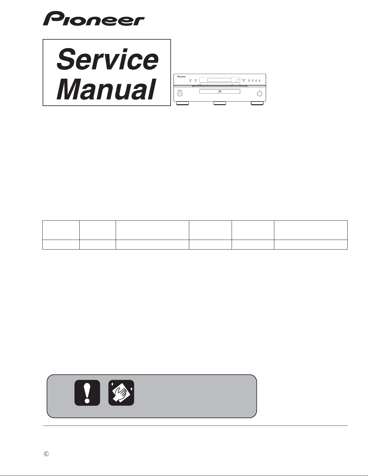
BDP-09FD
For details, refer to "Important Check Points for good servicing".
Blu-ray Disc PLAYER
BDP-09FD
THIS MANUAL IS APPLICABLE TO THE FOLLOWING MODEL(S) AND TYPE(S).
ORDER NO.
RRV3865
Model Type Power Requirement
BDP-09FD KU/CA AC 120 V 1 A
DVD
Region No.
BD
Region No.
Remarks
T-ZZY-001 DEC.
2008 Printed in Japan
1
ANY MEASUREMENTS NOT WITHIN THE
LIMITS OUTLINED ABOVE ARE INDICATIVE
OF A POTENTIAL SHOCK HAZARD AND
MUST BE CORRECTED BEFORE RETURNING THE APPLIANCE TO THE CUSTOMER.
2. PRODUCT SAFETY NOTICE
Many electrical and mechanical parts in the appliance
have special safety related characteristics. These are
often not evident from visual inspection nor the
protection afforded by them necessarily can be obtained
by using replacement components rated for voltage,
wattage, etc. Replacement parts which have these
special safety characteristics are identified in this
Service Manual.
Electrical components having such features are
identified by marking with a
on the schematics and
on the parts list in this Service Manual.
The use of a substitute replacement component which
does not have the same safety characteristics as the
PIONEER recommended replacement one, shown in the
parts list in this Service Manual, may create shock, fire,
or other hazards.
Product Safety is continuously under review and new
instructions are issued from time to time. For the latest
information, always consult the current PIONEER
Service Manual. A subscription to, or additional copies
of, PIONEER Service Manual may be obtained at a
nominal charge from PIONEER.
(FOR USA MODEL ONLY)
1. SAFETY PRECAUTIONS
The following check should be performed for the
continued protection of the customer and service
technician.
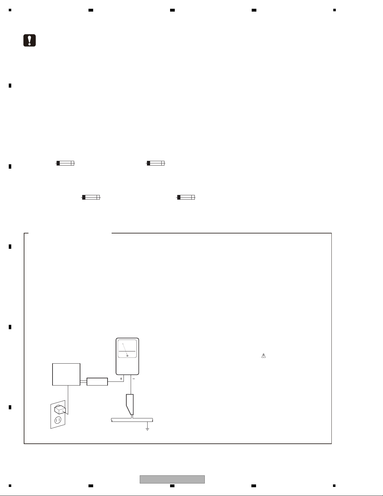
LEAKAGE CURRENT CHECK
Measure leakage current to a known earth ground
(water pipe, conduit, etc.) by connecting a leakage
current tester such as Simpson Model 229-2 or
equivalent between the earth ground and all exposed
metal parts of the appliance (input/output terminals,
screwheads, metal overlays, control shaft, etc.). Plug
the AC line cord of the appliance directly into a 120V
AC 60 Hz outlet and turn the AC power switch on. Any
current measured must not exceed 0.5 mA.
Device
under
test
Leakage
current
tester
Earth
ground
Reading should
not be above
0.5 mA
Also test with
plug reversed
(Using AC adapter
plug as required)
Test all
exposed metal
surfaces
AC Leakage Test
This service manual is intended for qualified service technicians; it is not meant for the casual
do-it-yourselfer. Qualified technicians have the necessary test equipment and tools, and have been
trained to properly and safely repair complex products such as those covered by this manual.
Improperly performed repairs can adversely affect the safety and reliability of the product and may
void the warranty. If you are not qualified to perform the repair of this product properly and safely,
you should not risk trying to do so and refer the repair to a qualified service technician.
WARNING
This product contains certain electrical parts contain chemicals which are known to the State of California to cause cancer,
birth defects or other reproductive harm.
Health & Safety Code Section 25249.6 - Proposition 65
NOTICE
(FOR CANADIAN MODEL ONLY )
Fuse symbols (fast operating fuse) and/or (slow operating fuse) on PCB indicate that replacement parts must
be of identical designation.
REMARQUE
(POUR MODÈLE CANADIEN SEULEMENT)
Les symboles de fusible (fusible de type rapide) et/ou (fusible de type lent) sur CCI indiquent que les pièces
de remplacement doivent avoir la même désignation.
2 3 4
SAFETY INFORMATION
A
B
C
D
E
F
2
1
2 3 4
BDP-09FD
5
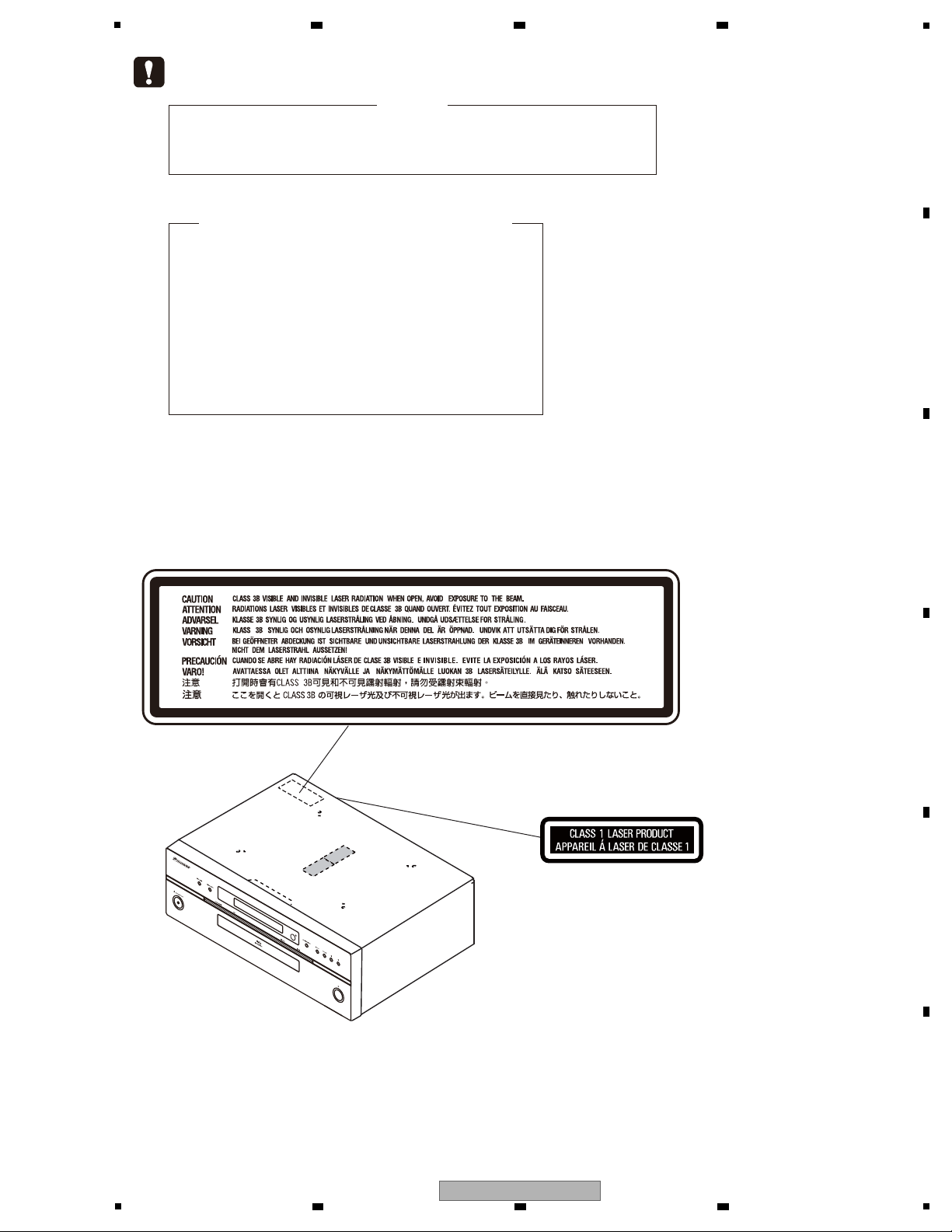
LABEL CHECK
(Printed on the Rear Panel)
The following caution label appears on your unit.
Location: inside of the unit
WARNING !
THE LASER COMPONENT IS CAPABLE OF EMITTING RADIATION EXCEEDING THE LIMIT
FOR CLASS 1.
A SPECIALLY INSTRUCTED PERSON SHOULD DO SERVICING OPERATION OF THE
APPARATUS.
Laser Pickup specifications and Laser characteristics
For BD Wave length : 405 nm
Operating output : 0.95 mW CW, Class 1M
Maximum output : Class 2 (under fault condition)
For DVD Wave length : 660 nm
Operating output : 1.06 mW CW, Class 1M
Maximum output : Class 2M (under fault condition)
For CD Wave length : 785 nm
Operating output : 1.34 mW CW, Class 1M
Maximum output : Class 1M (under fault condition)
VRW2262 - A
6 7 8
A
B
C
D
E
F
BDP-09FD
5
6 7 8
3
1
[Important Check Points for Good Servicing]
In this manual, procedures that must be performed during repairs are marked with the below symbol.
Please be sure to confirm and follow these procedures.
1. Product safety
Please conform to product regulations (such as safety and radiation regulations), and maintain a safe servicing environment by
following the safety instructions described in this manual.
1 Use specified parts for repair.
Use genuine parts. Be sure to use important parts for safety.
2 Do not perform modifications without proper instructions.
Please follow the specified safety methods when modification(addition/change of parts) is required due to interferences such as
radio/TV interference and foreign noise.
3 Make sure the soldering of repaired locations is properly performed.
When you solder while repairing, please be sure that there are no cold solder and other debris.
Soldering should be finished with the proper quantity. (Refer to the example)
4 Make sure the screws are tightly fastened.
Please be sure that all screws are fastened, and that there are no loose screws.
5 Make sure each connectors are correctly inserted.
Please be sure that all connectors are inserted, and that there are no imperfect insertion.
6 Make sure the wiring cables are set to their original state.
Please replace the wiring and cables to the original state after repairs.
In addition, be sure that there are no pinched wires, etc.
7 Make sure screws and soldering scraps do not remain inside the product.
Please check that neither solder debris nor screws remain inside the product.
8 There should be no semi-broken wires, scratches, melting, etc. on the coating of the power cord.
Damaged power cords may lead to fire accidents, so please be sure that there are no damages.
If you find a damaged power cord, please exchange it with a suitable one.
9 There should be no spark traces or similar marks on the power plug.
When spark traces or similar marks are found on the power supply plug, please check the connection and advise on secure
connections and suitable usage. Please exchange the power cord if necessary.
a Safe environment should be secured during servicing.
When you perform repairs, please pay attention to static electricity, furniture, household articles, etc. in order to prevent injuries.
Please pay attention to your surroundings and repair safely.
2. Adjustments
To keep the original performance of the products, optimum adjustments and confirmation of characteristics within specification.
Adjustments should be performed in accordance with the procedures/instructions described in this manual.
4. Cleaning
For parts that require cleaning, such as optical pickups, tape deck heads, lenses and mirrors used in projection monitors, proper
cleaning should be performed to restore their performances.
3. Lubricants, Glues, and Replacement parts
Use grease and adhesives that are equal to the specified substance.
Make sure the proper amount is applied.
5. Shipping mode and Shipping screws
To protect products from damages or failures during transit, the shipping mode should be set or the shipping screws should be
installed before shipment. Please be sure to follow this method especially if it is specified in this manual.
A
2 3 4
B
C
D
E
F
4
1
BDP-09FD
2 3 4

5
6 7 8
CONTENTS
SAFETY INFORMATION.......................................................................................................................................................... 2
1. SERVICE PRECAUTIONS....................................................................................................................................................7
1.1 NOTES ON SOLDERING............................................................................................................................................... 7
1.2 NOTE ON DISASSEMBLING/REASSEMBLING............................................................................................................ 7
1.3 NOTE ON REPLACING IC9011 .....................................................................................................................................7
1.4 NOTE ON REPLACING THE TRAY PANEL BASE AND TRAY ALUMINUM .................................................................7
2. SPECIFICATIONS.................................................................................................................................................................8
2.1 ACCESSORIES..............................................................................................................................................................8
2.2 SPECIFICATIONS .......................................................................................................................................................... 9
2.3 DISC/CONTENT FORMAT ........................................................................................................................................... 10
2.4 PANEL FACILITIES.......................................................................................................................................................14
3. BASIC ITEMS FOR SERVICE ............................................................................................................................................17
3.1 CHECK POINTS AFTER SERVICING ......................................................................................................................... 17
3.2 PCB LOCATIONS .........................................................................................................................................................18
3.3 JIGS LIST .....................................................................................................................................................................19
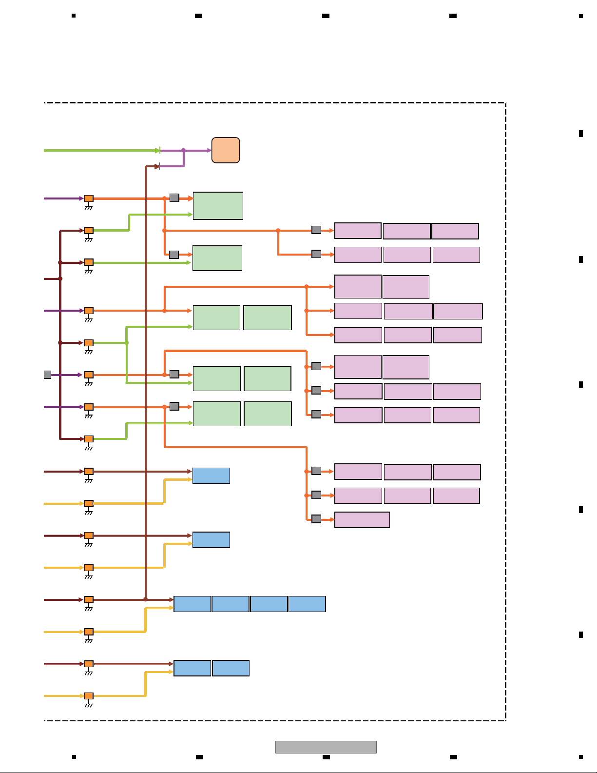
4. BLOCK DIAGRAM .............................................................................................................................................................. 20
4.1 OVERALL WIRING DIAGRAM ..................................................................................................................................... 20
4.2 BLOCK DIAGRAM........................................................................................................................................................ 22
4.3 POWER BLOCK DIAGRAM ......................................................................................................................................... 24
4.4 CLOCK BLOCK DIAGRAM........................................................................................................................................... 28
4.5 RESET BLOCK DIAGRAM........................................................................................................................................... 29
4.6 VIDEO BLOCK DIAGRAM............................................................................................................................................30
5. DIAGNOSIS ........................................................................................................................................................................31
5.1 POWER ON SEQUENCE.............................................................................................................................................31
5.2 TROUBLE SHOOTING.................................................................................................................................................32
5.3 RESET ON SEQUENCE .............................................................................................................................................. 33
6. SERVICE MODE................................................................................................................................................................. 34
6.1 OSD.............................................................................................................................................................................. 34
7. DISASSEMBLY ...................................................................................................................................................................44
8. EACH SETTING AND ADJUSTMENT................................................................................................................................58
8.1 NECESSARY ADJUSTMENT POINTS ........................................................................................................................58
8.2 FIRMWARE UPDATE ...................................................................................................................................................58
8.3 MODEL SETTING ........................................................................................................................................................59
8.4 CPRM ID NUMBER AND DATA SETTING ...................................................................................................................61
9. EXPLODED VIEWS AND PARTS LIST............................................................................................................................... 64
9.1 PACKING SECTION ..................................................................................................................................................... 64
9.2 EXTERIOR SECTION .................................................................................................................................................. 66
9.3 BOTTOM SECTION......................................................................................................................................................68
9.4 FRONT PANEL SECTION ............................................................................................................................................ 70
10. SCHEMATIC DIAGRAM....................................................................................................................................................72
10.1 SERVICE MAIN ASSY (1/13)(GUIDE PAGE).............................................................................................................72
10.2 SERVICE MAIN ASSY (2/13)(GUIDE PAGE).............................................................................................................78
10.3 SERVICE MAIN ASSY (3/13) ..................................................................................................................................... 84
10.4 SERVICE MAIN ASSY (4/13) ..................................................................................................................................... 86
10.5 SERVICE MAIN ASSY (5/13) ..................................................................................................................................... 88
10.6 SERVICE MAIN ASSY (6/13) ..................................................................................................................................... 90
10.7 SERVICE MAIN ASSY (7/13)(GUIDE PAGE)..........................................................................................
10.8 SERVICE MAIN ASSY (8/13) ..................................................................................................................................... 98
10.9 SERVICE MAIN ASSY (9/13) ................................................................................................................................... 100
10.10 SERVICE MAIN ASSY (10/13) ...............................................................................................................................102
10.11 SERVICE MAIN ASSY (11/13) ...............................................................................................................................104
10.12 SERVICE MAIN ASSY (12/13) ...............................................................................................................................106
10.13 SERVICE MAIN ASSY (13/13) ...............................................................................................................................108
10.14 SPATA ASSY...........................................................................................................................................................110
10.15 AUPW ASSY...........................................................................................................................................................112
10.16 AUJB ASSY (1/5)....................................................................................................................................................114
10.17 AUJB ASSY (2/5)....................................................................................................................................................116
10.18 AUJB ASSY (3/5)....................................................................................................................................................118
10.19 AUJB ASSY (4/5)....................................................................................................................................................120
10.20 AUJB ASSY (5/5)....................................................................................................................................................122
10.21 VOUT ASSY ........................................................................................................................................................... 124
10.22 FLKY ASSY ............................................................................................................................................................ 126
10.23 PSWB AND ACSW ASSY ......................................................................................................................................128
10.24 SYPS ASSY............................................................................................................................................................130
10.25 WAVEFORMS......................................................................................................................................................... 132
BDP-09FD
5
6 7 8
...................92
A
B
C
D
E
F
5

1
2 3 4
11. PCB CONNECTION DIAGRAM ......................................................................................................................................134
11.1 SERVICE MAIN ASSY..............................................................................................................................................134
11.2 SPATA ASSY .............................................................................................................................................................138
11.3 VOUT ASSY..............................................................................................................................................................139
A
11.4 AUPW ASSY.............................................................................................................................................................140
11.5 AUJB ASSY ..............................................................................................................................................................142
11.6 FLKY ASSY ..............................................................................................................................................................146
11.7 PSWB ASSY.............................................................................................................................................................148
11.8 ACSW ASSY.............................................................................................................................................................150
11.9 SYPS ASSY..............................................................................................................................................................152
12. PCB PARTS LIST ............................................................................................................................................................154
B
C
D
E
F
6
1
2 3 4
BDP-09FD
5
• For environmental protection, lead-free solder is used on the printed circuit boards mounted in this unit.
Be sure to use lead-free solder and a soldering iron that can meet specifications for use with lead-free solders for repairs
accompanied by reworking of soldering.
• Compared with conventional eutectic solders, lead-free solders have higher melting points, by approximately 40 ºC.
Therefore, for lead-free soldering, the tip temperature of a soldering iron must be set to around 373 ºC in general, although
the temperature depends on the heat capacity of the PC board on which reworking is required and the weight of the tip of
the soldering iron.
Do NOT use a soldering iron whose tip temperature cannot be controlled.
Compared with eutectic solders, lead-free solders have higher bond strengths but slower wetting times and higher melting
temperatures (hard to melt/easy to harden).
The following lead-free solders are available as service parts:
• Parts numbers of lead-free solder:
GYP1006 1.0 in dia.
GYP1007 0.6 in dia.
GYP1008 0.3 in dia.
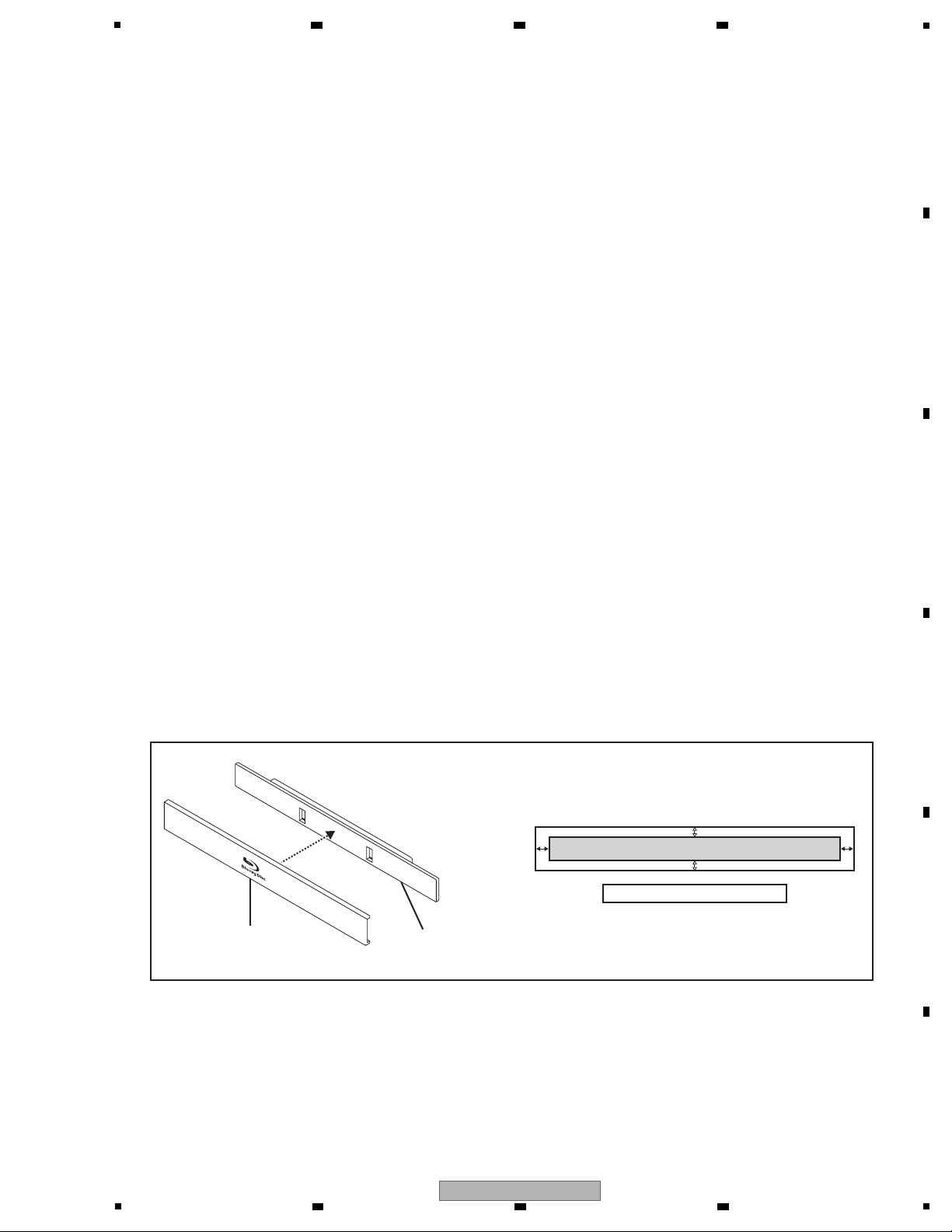
• For improvement of audio quality, many special screws and acetate tapes are used in this unit. Be careful when
disassembling/reassembling this unit, and be sure to restore the unit to its original state.
• As IC9011 (ROM) on the SERVICE MAIN Assy is fixed to the board with a special adhesive, it is not provided as a
service part. If replacement of IC9011 (ROM) is required, replace the entire SERVICE MAIN Assy.
• As the tray aluminum (VAH1467) and the tray panel base (VNK6455) are strongly adhered with double-back tape,
replace both parts when either needs to be replaced.
For attachment, adhere the tray aluminum (VAH1467) so that it is placed at the center of the tray panel base (VNK6455).
Tray aluminum
(VAH1467)
Tray panel base
(VNK6455)
Adhere the sheet at the center.
6 7 8
1. SERVICE PRECAUTIONS
1.1 NOTES ON SOLDERING
1.2 NOTE ON DISASSEMBLING/REASSEMBLING
A
B
1.3 NOTE ON REPLACING IC9011
1.4 NOTE ON REPLACING THE TRAY PANEL BASE AND TRAY ALUMINUM
C
D
E
5
6 7 8
BDP-09FD
F
7
1
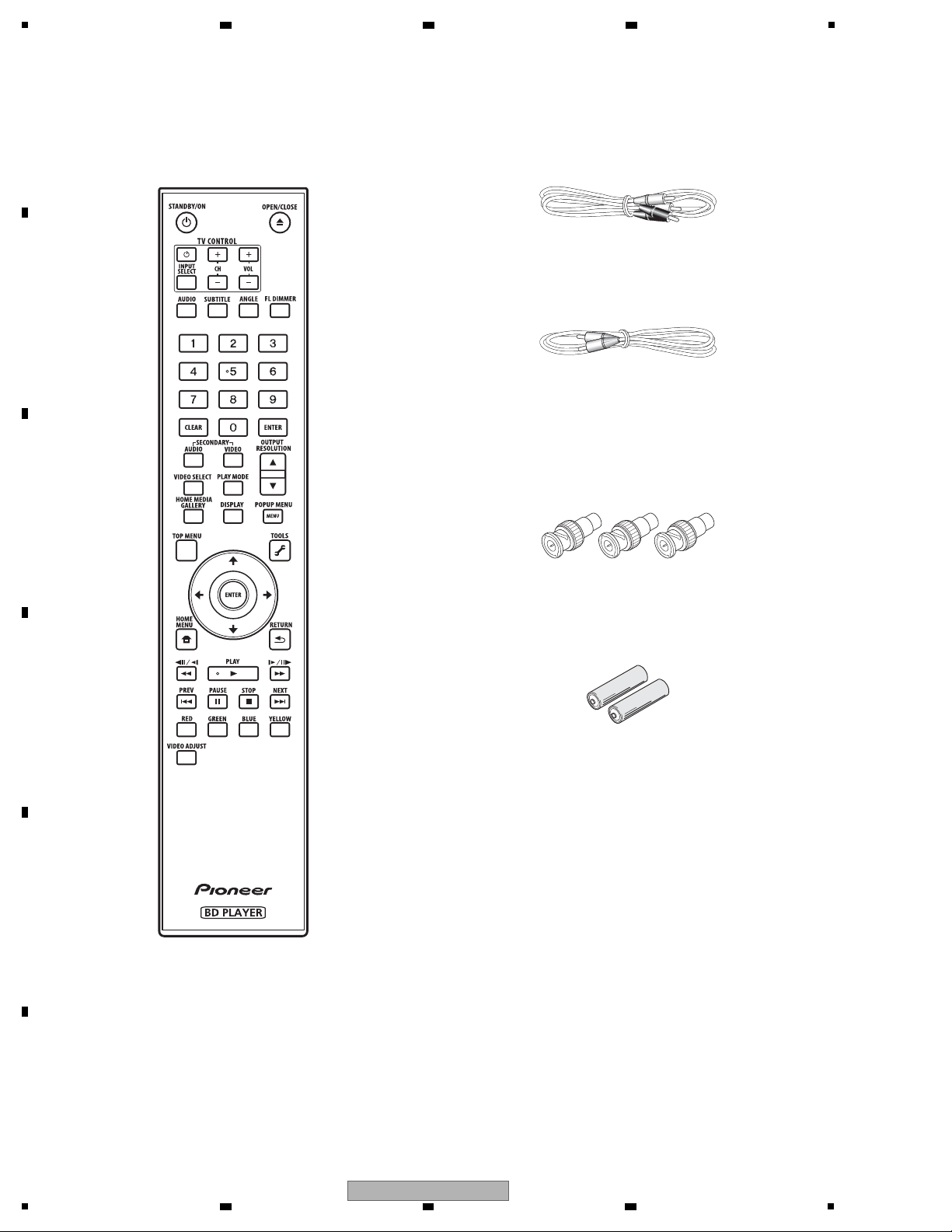
Remote control x 1
(VXX3316)
Operating instructions
(VRB1508)
BNC-RCA adapter x 3
(AKX1052)
Use this to connect an RCA pin type
cable to the COMPONENT VIDEO
terminal.
Audio cable (white/red) x 1
(VDE1064) L=1.5 m
Video cable (yellow) x 1
(VDE1065) L=1.5 m
AA/R6 dry cell batteries x 2
LAN cable x 1
(VDE1098)
Power cord x 1
(ADG7061)
Warranty card
2. SPECIFICATIONS
2.1 ACCESSORIES
A
2 3 4
B
C
D
E
F
8
1
2 3 4
BDP-09FD

5
Model BDP-09FD
Type Blu-ray Disc PLAYER
Rated voltage AC 120 V
Rated frequency 60 Hz
Power consumption 58 W
Power consumption (standby) 0.3 W
Weight 14.3 kg (31 lb 9 oz)
External dimensions (inc luding projecting parts) 420 mm (W) x 143 mm (H) x 365 mm (D)
(16
9
/16 in. (W) x 5 11/16 in. (H) x 14 6/16 in. (D))
Tolerable operating temperature +5 °C to +35 °C (+41 °F to +95 °F)
Tolerable operating humidity 5 % to 85 % (no condensation)
Output terminals
HDMI 2 sets, 19-pin: 5 V, 250 mA (Total value for the HDMI OUT
(MAIN) and HDMI OUT (SUB) terminals)
Video outputs Video 1 set, RCA jack: 1.0 Vp-p (75 Ω)
S-Video 1 set, S-Video jack:
Y (luminance): 1.0 Vp-p (75 Ω)
C (color): 0.286 Vp-p (75 Ω)
Component video 1 set, BNC jacks:
Y: 1.0 Vp-p (75 Ω)
P
B, PR: 0.7 Vp-p (75 Ω)
Audio outputs 7.1-channel (multi-channel: front left/
right, surround left/right, center,
surround back left/right, subwoofer)
1 set, Number of channels: 8, RCA jacks
Audio output level 200 mVrms (1 kHz, –20 dB)
Frequency response 4 Hz to 88 kHz (192 kHz sampling)
S/N ratio 115 dB
Dynamic range 103 dB
Total harmonic distortion 0.0015 %
Wow & flutter Below measurable limits (±0.001 % W. PEAK)
Digital audio outputs Optical 1 set, Optical digital jack
Coaxial 1 set, RCA jack
LAN 1 set, Ethernet jack (100BASE-TX)
Control Input 1 set, Minijack (3.5 ø)
Note
• The specifications and design of this product are subject to change without notice.
• This product includes FontAvenue
®
fonts licensed by NEC Corporation.
FontAvenue is a registered trademark of NEC Corporation.
6 7 8
2.2 SPECIFICATIONS
A
B
C
D
E
BDP-09FD
5
6 7 8
F
9
1
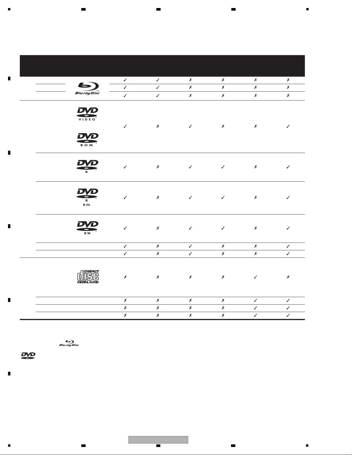
[1] Playable discs
Discs with the logo marks below indicated on the disc label, package or jacket can be played.
“Blu-ray Disc” and are trademarks.
is a trademark of DVD Format/Logo Licensing Corporation.
Disc type
Logo Application format
BDMV
1
1. Including the AVCHD format.
BDAV DVD-Video DVD VR
CD-DA
DTS-CD
DATA-DISC
2
2. Discs on which video, image or audio files are recorded
BD
BD-ROM
BD-R
BD-RE
DVD
DVD-ROM
DVD-R
DVD-R DL
(Dual Layer)
DVD-RW
DVD+R
DVD+RW
CD
CD-DA
(Audio CD)
CD-R
CD-RW
CD-ROM
2 3 4
2.3 DISC/CONTENT FORMAT
A
B
C
D
E
F
10
1
BDP-09FD
2 3 4
5
Discs that cannot be played
• Non-finalized (Non-closed) BD-R discs in the BDMV format
•HD DVDs
•DVD Audio discs
•DVD-RAM discs
•
Non-finalized DVD-R/-RW/+R/+RW discs in the DVD-Video
format and AVCHD format
• Non-finalized Dual Layer DVD-R discs in the DVD VR format
• Non-finalized CD-R/-RW discs
• SACDs
• Video CDs
•SVCDs
This player conforms to NTSC standards. Discs for which “NTSC” is
indicated on the disc label, package or jacket can be played.
Note
•
Some discs cannot be played, even if one of the logo marks on
the previous page is indicated.
• To play 8 cm discs, set the disc in the 8 cm disc depression in
the center of the disc tray. No adapter is necessary. 8 cm BDROMs cannot be played.
About audio formats
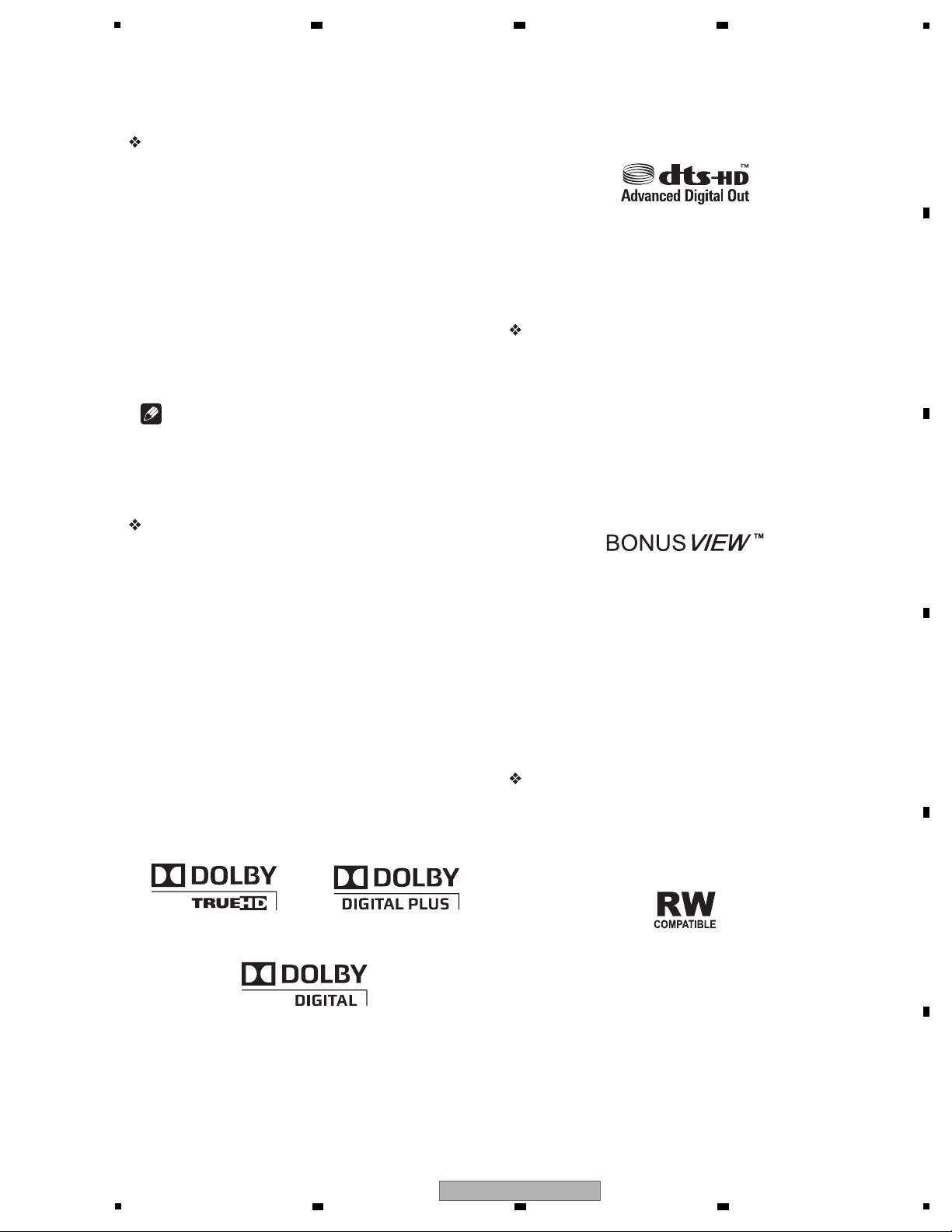
The following audio formats are supported on this player:
• Dolby TrueHD
• Dolby Digital Plus
• Dolby Digital
• DTS-HD Master Audio
• DTS-HD High Resolution Audio
• DTS Digital Surround
•MPEG
• MPEG-2 AAC
• Linear PCM
To enjoy the surround sound of Dolby TrueHD, Dolby Digital Plus,
DTS-HD Master Audio and DTS-HD High Resolution Audio, it is
recommended to connect the player to an AV receiver or amplifier
compatible with these audio formats using an HDMI cable. After
loading a BD containing sound in one of these audio formats, select
the audio format on the menu screen.
Manufactured under license from Dolby Laboratories. Dolby and the
double-D symbol are trademarks of Dolby Laboratories.
Manufactured under license under U.S. Patent #: 5,451,942;
5,956,674; 5,974,380; 5,978,762; 6,487,535 & other U.S. and worldwide
patents issued & pending. DTS is a registered trademark and the DTS
logos, Symbol, DTS-HD and DTS-HD Advanced Digital Out are
trademarks of DTS, Inc. © 1996-2007 DTS, Inc. All Rights Reserved.
Playing BDs
• BDs (BDMV) compatible with the formats below can be played.
– Blu-ray Disc Read-Only (ROM) Format Version 2
– Blu-ray Disc Recordable (R) Format Version 2 (finalize (close)
them before playing them on this player)
– Blu-ray Disc Rewritable (RE) Format Version 3
This player supports BD-ROM Profile 1 Version 1.1.
BONUSVIEW Functions such as playback of secondary video
(Picture-in-Picture) and secondary audio can be used. For
details on secondary video and secondary audio playback, refer
to the disc’s instructions.
“BONUSVIEW” is trademark of Blu-ray Disc Association.
When a BD-ROM is played, additional data may be stored in the
player’s memory area (local storage). If the message indicating
low memory (local storage) appears, erase the BDMV data.
• BDs (BDAV) compatible with the formats below can be played.
– Blu-ray Disc Recordable (R) Format Version 1
– Blu-ray Disc Rewritable (RE) Format Version 2
• Dual Layer BDs can be played.
• Video, image and audio files recorded on BDs cannot be played.
• 8 cm BD-ROMs cannot be played.
Playing DVDs
•DVD-Video can be played.
•
DVD-R/-RW/+R/+RW discs recorded in the DVD-Video format
can be played (finalize them before playing them on this player).
•
DVD-R/-RW discs recorded in the VR format (Video Recording
format) can be played.
This label indicates playback compatibility with DVD-RW discs
recorded in VR format (Video Recording format). However, for discs
recorded with a record-only-once encrypted program, playback can
only be achieved using a CPRM compatible device.
6 7 8
A
B
C
D
E
5
BDP-09FD
6 7 8
F
11
1
•DVDs recorded in the AVCHD format can be played (finalize
them before playing them on this player).
“AVCHD” and the “AVCHD” logo are trademarks of Panasonic
Corporation and Sony Corporation.
• Video, image and audio files recorded on DVD-R/-RW/+R/+RW
discs can be played. See Playable files below.
• Dual Layer DVDs can be played. However, non-finalized Dual
Layer DVD-R discs recorded in the VR format cannot be played
(finalize them before playing them on this player).
• HD DVD, DVD Audio and DVD-RAM discs cannot be played.
About region numbers
Blu-ray Disc Player and BD-ROM or DVD-Video discs are assigned
region numbers according to the region in which they are sold.
This player’s region numbers are:
• BD-ROM: A
•DVD-Video: 1
Discs not including these numbers cannot be played. Discs
playable on this player are as shown below.
• BDs: A (including A) and ALL
•DVDs: 1 (including 1) and ALL
Playing CDs
• Audio CDs (CD-DAs and DTS-CDs) can be played.
• Video, image and audio files recorded on CDs can be played.
See Playable files below.
• CD-R/-RW discs that are not finalized cannot be played.
• SACD, Video CD and Super VCD discs cannot be played.
• Regarding copy protected CDs: This player is designed to
conform to the specifications of the Audio CD format. This
player does not support the playback or function of discs that do
not conform to these specifications.
DualDisc playback
A DualDisc is a new two-sided disc, one side of which contains DVD
content — video, audio, etc. — while the other side contains nonDVD content such as digital audio material.
The DVD side of a DualDisc can be played on this player (excluding
any DVD-Audio content).
The non-DVD, audio side of the disc is not compatible with this
player.
It is possible that when loading or ejecting a DualDisc, the opposite
side to that being played will be scratched. Scratched discs may not
be playable.
For more detailed information on the DualDisc specification, please
refer to the disc manufacturer or disc retailer.
Playing discs created on computers or BD/
DVD recorders
• It may not be possible to play discs recorded using a computer
due to the application settings or computer’s environment
settings. Record discs in a format playable on this player. For
details, contact the dealer.
• It may not be possible to play discs recorded using a computer
or a BD/DVD recorder, if burn quality is not good due to
characteristics of the disc, scratches, dirt on the disc, dirt on the
recorder’s lens, etc.
[2] Playable files
Video, image and audio files recorded on DVDs and CDs can be
played.
Caution
•In DVD, only the one recorded by the ISO 9660 file system can be
played.
• Some files may not be playable.
•
For some files, it may not be possible to use certain functions
during playback.
•
It may not be possible to play some files, even if they have the
extension of a file playable on this player.
• Files protected by DRM (Digital Rights Management) cannot be
played (not including DivX VOD files).
Supported video file formats
•DivX
DivX is a media technology created by DivX, Inc. DivX media files
contain not only video but also advanced media features like
subtitles and alternate audiotracks, etc.
Conform to the size under 720 x 480 pixels.
DivX files encoded with GMC/Qpel option cannot be played.
Only audio signals with MP3 or Dolby Digital (AC3) format are
output.
Note that files other than the ones containing DivX video cannot
be played, even if they have the extension “.avi”.
®
Official DivX Certified product.
®®
Plays all versions of DivX video (including DivX 6) with standard
®
playback of DivX media files.
DivX, DivX Certified, and associated logos are trademarks of DivX,
Inc. and are used under license.
A
2 3 4
B
C
D
E
F
12
BDP-09FD
1
2 3 4

5
Note
• DivX VOD files are protected by DRM. They can only be played
on registered devices.
–
You may be requested by the file distributor to input the DivX
VOD registration code for authorization of the player in order
to play DivX VOD files. This player’s DivX VOD registration
code can be checked at Initial Setup Playback DivX
VOD Registration Code.
–
DivX VOD files for which the player’s DivX VOD registration
code is not authorized cannot be played (Authorization
Error is displayed).
– The number of views is restricted for some DivX VOD files.
When such files are played on this player, the remaining
number of views is displayed. Files for which the remaining
number of views has reached 0 cannot be played (Rental
Expired is displayed). Files for which the number of views is
not restricted can be played as many times as you like (the
remaining number of views is not displayed).
Supported image file formats
• JPEG
File format: JFIF Ver1.02/Exif Ver.2.2
Resolution: Up to 4096 x 4096 pixels
Only baseline JPEG files are supported.
Supported audio file formats
• Windows Media™ Audio 9 (WMA9)
Bit rate: Up to 192 kbps
Sampling frequencies: 22.05 kHz, 32 kHz, 44.1 kHz and 48 kHz
Windows Media is either a registered trademark or trademark of
Microsoft Corporation in the United States and/or other countries.
This product includes technology owned by Microsoft Corporation
and cannot be used or distributed without a license from
Microsoft Licensing, Inc.
• MPEG-1 Audio Layer 3 (MP3)
Bit rate: Up to 320 kbps
Sampling frequencies: 8 kHz, 11.025 kHz, 12 kHz, 16 kHz,
22.05 kHz, 24 kHz, 32 kHz, 44.1 kHz and 48 kHz
Playable file extensions
• Video files
.divx and .avi
• Image files
.jpg and .jpeg
• Audio files
.wma and .mp3
6 7 8
A
B
C
D
E
F
BDP-09FD
5
6 7 8
13
1
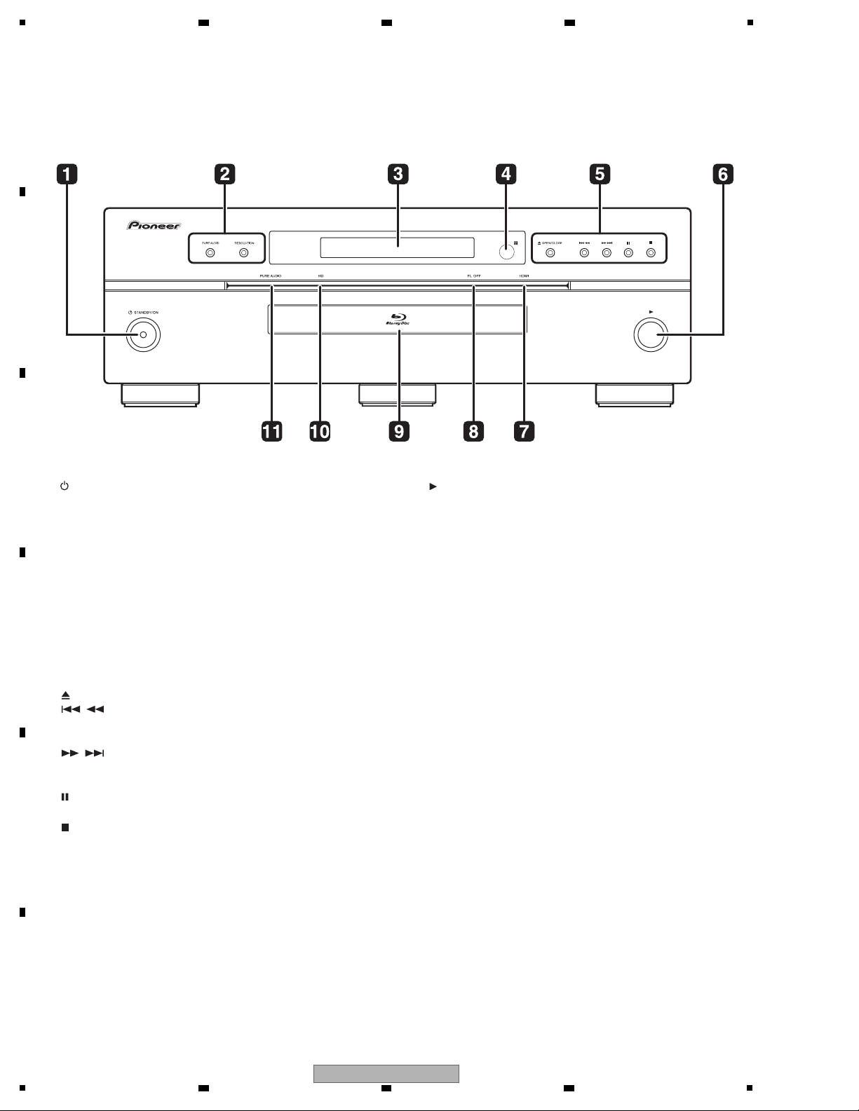
[1] Front Panel
1 STANDBY/ON
Press to turn the power on and off.
2 PURE AUDIO – High quality audio signals with any extraneous
noise eliminated are output.
RESOLUTION – Press to switch the output video resolution from
HDMI OUT or COMPONENT VIDEO output terminals.
3 Front panel display
4 Remote control sensor
Point the remote control to this, then operate it within approximately
23 feet.
The player may have trouble capturing remote control signals if
there is a fluorescent light nearby. If this happens, move the player
away from the fluorescent light.
5 OPEN/CLOSE – Press to open and close the disc tray.
/ – Press to skip to the beginning of the previous title/
chapter/track/file. Press and hold to start reverse scanning.
/ – Press to skip to the beginning of the next title/
chapter/track/file. Press and hold to start forward scanning.
– Press during playback to pause. Press again to restart
playback.
– Press to stop playback.
6
Press to start playback.
7 HDMI indicator
This lights when an HDMI-compatible device is connected to an
HDMI OUT (MAIN) or HDMI OUT (SUB) terminal.
8 FL OFF indicator
This lights when Off is selected with FL DIMMER.
9 Disc tray
10 HD indicator
This lights when an HDMI cable is connected and video signals are
being output with a resolution of 1080/24p, 1080/60i, 1080/60p or
720/60p. It also lights when a component video cable is connected
and video signals are being output with a resolution of 1080/60i or
720/60p.
11 PURE AUDIO indicator
This lights when PURE AUDIO is set to Mode 1 or Mode 2.
2.4 PANEL FACILITIES
A
B
2 3 4
C
D
E
F
14
1
2 3 4
BDP-09FD
5
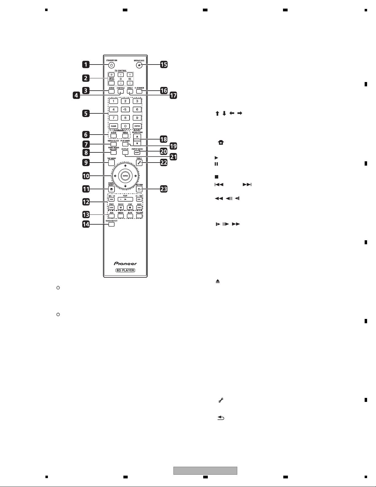
[2] Remote Control
1 STANDBY/ON
Press to turn the power on and off.
2 TV CONTROL
Your TV can be controlled using the player’s remote control.
– Press to turn the TV’s power on and off.
INPUT SELECT – Press to switch the TV’s input.
CH +/– – Press to select the TV channel.
VOL +/– – Press to adjust the volume.
3 AUDIO
Press to switch the audio streams/channels.
4 SUBTITLE
Press to switch the subtitles.
5 Number buttons – Use these to select and play the title/
chapter/track you want to view or listen to and to select items
from menus.
CLEAR – Press to clear the numeric number, etc.
ENTER – Press to execute the selected item or enter a setting
that has been changed, etc.
6 SECONDARY AUDIO – When playing a BD-ROM on which
secondary audio is recorded, press to switch to the secondary
audio.
SECONDARY VIDEO – When playing a BD-ROM on which
secondary video (Picture-in-Picture) is recorded, press to switch
to the secondary video.
7 VIDEO SELECT
Press to switch the video output signal to be viewed between the one
output from the HDMI OUT (MAIN) terminal, the HDMI OUT (SUB)
terminal and an analog output terminal (COMPONENT VIDEO, S-
VIDEO or VIDEO output terminals).
8 HOME MEDIA GALLERY
Press to display/hide the Home Media Gallery screen.
9TOP MENU
Press to display the top menu of the BD-ROM or DVD-Video.
10 / / / – Use to select items, change settings and move
the cursor.
ENTER – Press to execute the selected item or enter a setting
that has been changed, etc.
11 HOME MENU
Press to display/hide the Home Menu.
12 PLAY – Press to start playback.
PAUSE – Press to pause playback. Press again to restart
playback.
STOP – Press to stop playback.
PREV/ NEXT – Press to skip to the beginning of the
previous/next title/chapter/track/file.
// – Press during playback to start reverse scanning.
While playback is paused, press for step reverse playback. Press
and hold while playback is paused for reverse slow motion
playback.
// – Press during playback to start forward scanning.
While playback is paused, press for step forward playback.
Press and hold while playback is paused for forward slow
motion playback.
13 RED/GREEN/BLUE/YELLOW
Use these to navigate BD-ROM menus.
14 VIDEO ADJUST
Press to display/hide the Video Adjust menu.
15 OPEN/CLOSE
Press to open and close the disc tray.
16 FL DIMMER
Press to switch the brightness of the front panel display.
The FL OFF indicator lights when Off is selected.
17 ANGLE
Press to switch the BD-ROM or DVD-Video camera angles.
18 OUTPUT RESOLUTION
Use these to switch the output video resolution from the HDMI OUT
or COMPONENT VIDEO output terminals.
19 PLAY MODE
Press to display/hide the Play Mode screen.
20 POP UP MENU/MENU
Press to display the BD-ROM or DVD-Video menus.
21 DISPLAY
Press to display disc information.
22 TOOLS
Press to display/hide the TOOLS menu.
23 RETURN
Press to return to the previous screen.
5
6 7 8
BDP-09FD
6 7 8
A
B
C
D
E
F
15
1
[3] Front Panel Display
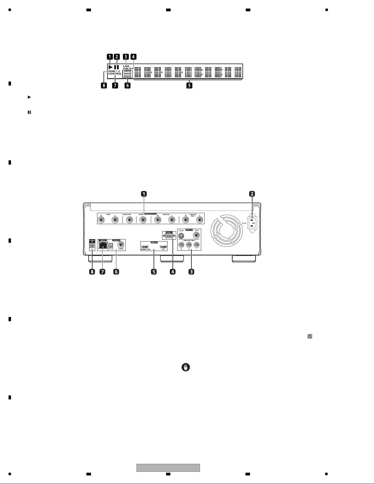
1
Lights during playback.
2
Lights when playback is paused.
3LAN
Lights when there is an active local area network (LAN) connection.
4PQLS
Lights when the PQLS function is activated.
5 Character display
Displays the title/chapter/track number, elapsed time, etc.
6 24HZ/50HZ/60HZ
The frequency of the video frame or field being output lights.
7CONTROL
Lights when the KURO LINK function is activated.
8 HDMI 1 2
HDMI 1 lights when VIDEO SELECT is pressed and the HDMI OUT
(MAIN) terminal is selected. HDMI 2 lights when the HDMI OUT
(SUB) terminal is selected.
[4] Rear Panel
1 AUDIO OUT (7.1 ch) terminals
Connect with the multi-channel (7.1- or 5.1-channel) audio input
terminals on an AV receiver or amplifier, etc..
To connect to the 2-channel audio input terminals on a TV, etc.,
connect to FRONT (L/R).
2 AC IN
Connect the power cord here.
3 VIDEO OUT terminals
VIDEO – Connect with the video input terminal on a TV, AV
receiver or amplifier, etc..
S-VIDEO – Connect with the S-Video input terminal on a TV, AV
receiver or amplifier, etc..
COMPONENT VIDEO (BNC jacks) – Connect with the
component video input terminals on a TV, AV receiver or
amplifier, etc..
4 RS-232C terminal
This terminal is not used.
5 HDMI OUT terminals
MAIN (KURO LINK) – Connect with an HDMI-compatible TV, AV
receiver or amplifier, etc..
SUB – Connect with an HDMI-compatible TV, projector, etc..
This terminal outputs linear PCM 2-channel audio signals.
Do not connect an AV receiver or amplifier to this terminal.
Also note that the KURO LINK function will not work for
devices connected to this terminal.
6 DIGITAL OUT (COAXIAL/OPTICAL) terminals
Connect with the digital audio input terminal on an AV receiver or
amplifier, etc..
7 LAN (100) terminal
Ethernet port for 100BASE-TX (100 Mbps) network connection.
8 CONTROL IN terminal
Use to control this player from the remote sensor of another Pioneer
component with a CONTROL OUT terminal and bearing the
mark. Connect the CONTROL OUT terminal of the other component
to CONTROL IN on this player using a mini-plug cord (commercially
available).
Caution
• Be sure to connect cables for outputting the audio and video
signals.
• When connected via System Control, point the remote control
toward the connected component (such as an AV receiver or
amplifier). The remote will not work correctly when pointed at
this player.
• You cannot use System Control with components that do not
have a System Control terminal or with components
manufactured by companies other than Pioneer.
A
2 3 4
B
C
D
E
F
16
1
2 3 4
BDP-09FD

5
Items to be checked after repair (BD players)
To ensure the quality of the product after repair, check the recommended items shown below:
See the table below for the items to be checked regarding video and audio:
* (ex.) SC-LX81, SC-LX71.
Item to be checked regarding video Item to be checked regarding audio
Block noise Distortion
Horizontal noise Noise
Dot noise Volume too low
Disturbed image (video jumpiness) Volume too high
Too dark Volume fluctuating
Too bright Sound interrupted
Mottled color
Color disappearance
No. Procedures Item to be checked
1 Check the version of the firmware in Service mode.
The version must be the latest.
If the version is not the latest, update the firmware.
2
Check if all the symptoms pointed out by the customer have been
addressed. If a symptom pointed out by the customer is
attributable to a particular disc, that disc must be played back.
The symptoms in question must not be reproduced.
Video, audio, and operations must be normal.
3
Measure playback error rates at the innermost and outermost
tracks, by playing back the following discs:
BD-ROM test disc (GGV1308)
DVD test disc (GGV1025)
If the symptoms are related to the PQLS (Precision Quartz Lock
System), check PQLS operations.
(For checking PQLS operations, connection with an amplifier*
that supports the PQLS is required.)
The error rates must be 1.0e-3 or less.
This procedure can determine if the drive is degraded.
For checking PQLS operations, connect the player with the
customer’s amplifier then check that “PQLS” is lit in the display
window on the unit. (See [3] Front Panel Display in
“2.4 PANEL FACILITIES.”)
4 Check playback of a CD disc (track search). Audio and operations, such as a search, must be normal.
5
Check playback of a DVD disc (menu operations, title/chapter
search).
Video, audio, and operations, such as a search, must be normal.
6
Check playback of a BD disc (menu operations, title/chapter
search).
Video, audio, and operations, such as a search, must be normal.
7 Check the cabinet.
Check for any scratches or dirt that have been made or attached
on the cabinet after receiving the product for repair.
Before shipping out the product, be sure to clean the following positions by using the prescribed cleaning tools:
Position to be cleaned Cleaning tools
Pickup lenses Cleaning liquid : GEM1004
Cleaning paper : GED-008
Position to be cleaned Cleaning tools
Fans Cleaning paper : GED-008
Cleaning
6 7 8
3. BASIC ITEMS FOR SERVICE
3.1 CHECK POINTS AFTER SERVICING
A
B
C
D
E
F
BDP-09FD
5
6 7 8
17
1
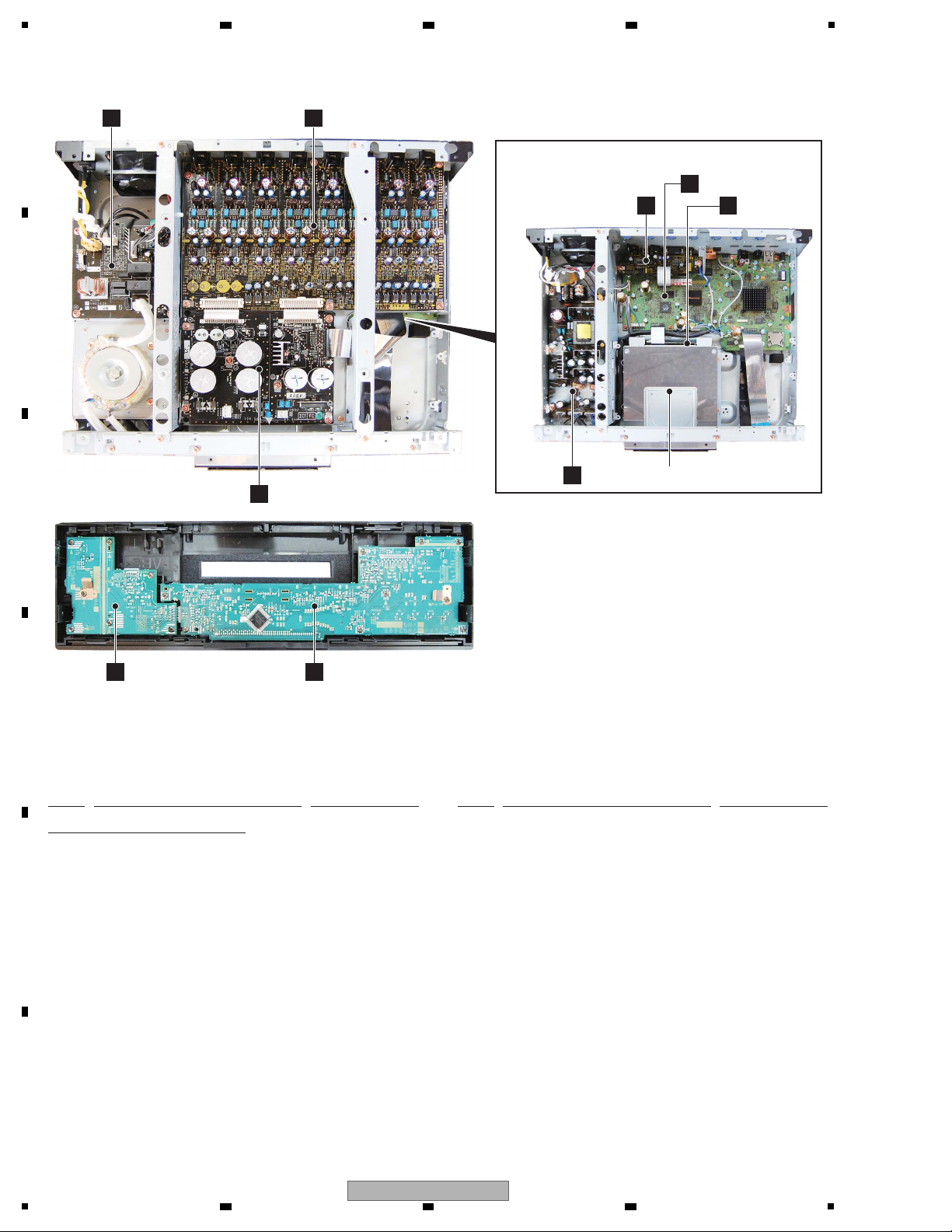
NSP 1..FLKB ASSY VWM2482
2..FLKY ASSY VWG2626
2..PSWB ASSY VWG2627
NSP 1..AVJB ASSY VWM2483
2..AUJB ASSY VWG2630
2..VOUT ASSY VWV2381
NSP 1..AUPB ASSY VWM2484
2..AUPW ASSY VWG2628
2..ACSW ASSY VWG2629
1..SERVICE MAIN ASSY VXX3348
NSP 2..MAIN ASSY VWV2382
2..SPATA ASSY VWV2387
> 1..SYPS ASSY VWR1422
1..BD/DVD/CD DRIVE
VXX3343
(BDR-L04H-XA/XV/5)
G
PSWB Assy
F
FLKY Assy
C
AUPW Assy
I
SYPS Assy BD/DVD/CD DRIVE
H
ACSW Assy
D
AUJB Assy
E
VOUT Assy
B
S PATA Assy
A
SERVICE MAIN Assy
NOTES: - Parts marked by “NSP” are generally unavailable because they are not in our Master Spare Parts List.
-
The > mark found on some component parts indicates the importance of the safety factor of the part.
Therefore, when replacing, be sure to use parts of identical designation.
Mark No. Description Part No. Mark No. Description Part No.
LIST OF ASSEMBLIES
3.2 PCB LOCATIONS
A
2 3 4
B
C
D
E
F
18
BDP-09FD
1
2 3 4

5
Service Remote Control Unit
GGF1067
DVD Test Disc (DVD-Video)
BD-ROM Test Disc
GGV1334
Adjustment, diagnosis
Name Jig No. Remarks
Check of DVD-Video
Check of BD-ROM
ID Data Disc for Blu-ray player
GGV1025
GGV1308
Diagnosis (ID data setting)
Jigs List
Disc Ejection Rod
GGF1529 Emergency Disc Ejection
3.3 JIGS LIST
6 7 8
A
B
C
D
E
5
6 7 8
BDP-09FD
F
19
1
HVOL_DET
GND
V+5E
XAMUTE
GND
XDACRST
GND
GND
ML1
ML2
MC
MD
GND
MCLK
GND
LRCK
GND
BCK
GND
ADATA3
GND
ADATA2
GND
ADATA1
GND
ADATA0
GND
GND
LED_FL_OFF
V+3R3D
GND
GND
FANCTL_SW1
LED_PON
IR
KEY1
GND
V+5E
KEY0
GND
LED_A_MODE
FLSTRB
GND
FLCLK
LED_HD
LED_HDMI
GND
GND
LED_BLUE
GND
GND
FANCTL_SW2
V+3R3SE
GND
FLDATA
GND
GND
GND
GND
V+5E
GND
XAMUTE
GND
XDACRST
GND
GND
ML1
ML2
MC
MD
GND
MCLK
GND
LRCK
GND
BCK
GND
ADATA3
GND
ADATA2
GND
ADATA1
GND
ADATA0
GND
GNDS
UREG-17V
UREG-17V
UREG-17V
GNDA
GNDA
GNDA
UREG17V
UREG17V
UREG17V
GNDA
GNDA
GNDA
UREG17V_DAC
UREG17V_DAC
UREG17V_DAC
GNDA
GNDA
GNDA
GNDD
GNDD
UREG+5V
UREG+5V
UREG+5V
UREG+5V
GNDD
GNDD
AUDIO_CT
AUDIO_1
AUDIO_2
DIGTAL1
DIGTAL2
GND
LED_PON
KEY0
V+12
GND_LED
GND_LED
GND_FL
V-23
GND_FL
FLDC+
FLDC-
GND
V+5E
GND
V+3R3E
GND
232C_CTS
232C_RTS
232C_Tx
232C_Rx
GND
V+5AD_V
V_MUTE
LETTER
SQUEESE
GND
A_VYOUT_DAC
GND
A_VCOUT_DAC
GND
A_VVOUT_DAC
CN4201
VKN1413-
1
2
3
4
5
6
7
8
9
CN1301
VKN2048-
1
2345678
9
101112131415161718192021222324252627282930
CN1001
CKS-556
1
2
3
CN1301
CKS-555
1
2
CN2000
VKN1610-
123456789
1011121314151617181920
CN6001
VKN1610-
123456789
1011121314151617181920
CN8901
VKN1618-
1
2
3
4
5
6
7
8
9
10
11
12
13
14
15
16
17
18
19
20
21
22
23
24
25
26
27
28
CN1402
VKN1618-
1
2
3
4
5
6
7
8
9
10
11
12
13
14
15
16
17
18
19
20
21
22
23
24
25
26
27
28
CN1401
VKN2008- (B TO B)
1
2
3
4
5
6
7
8
9
10
11
12
14
15
16
17
18
19
20
21
22
23
24
25
26
27
13
CN901
VKN2011- (B TO B)
1
2
3
4
5
6
7
8
9
10
11
12
14
15
16
17
18
19
20
21
22
23
24
25
26
27
13
CN1002
VKN2008- (B TO B)
123456789
101112141516171819202122232425
26
27
13
CN1001
VKN2011- (B TO B)
1
234
56789
1011121415161718192021222324252627
13
CN101
VKN1290-
123
45678
9
101112131415161718192021222324252627282930
CN102
AKM1359- (B TO B)
1
2
3
4
5
6
7
8
9
10
11
CN301
AKP1299- (B TO B)
1
2
3
4
5
6
7
8
9
10
11
VKN1322-A
CN4402
123456789
10
1112131415161718192021222324252627
28
29
30
SBRFR
7.1ch
Optical
AUDIO OUT
JA4351
DIGITAL
SR IN
SH_ICE (NO USE)
GND
GND
V+3R3D
AUDCK
AUDATA0
M32TMS
M32TDI
M32TDO
M32TCK
GND
V+5E
TXD_PCON
RXD_PCON
GND
DBGP2
DBGP1
DBGP0
XDBG_RST
Sub- com Debug
RKN1004
VDA2193-
V+3R3D
NC
M32TRST_N
GND
AUDATA1
GND
AUDATA2
GND
AUDATA3
GND
AUDSYNC
GND
SH_TCK
SH_TMS
GND
SH_TRST_N
MPMD
SH_TDI
SH_TDO
ASEBRKAL_N
RESET_N
JA101
SD CARD
DKP3748-A
JA3701
VDA2194-
SUB TRANS
FL LFE C SR SL SBL
JA201 JA301 JA401 JA501 JA601 JA701 JA801
LAN
RS-232C
VDA2204-
AKB7102
JA2100
JA2101
AKP1239
JA2300
AKP1213
S-VIDEO COMPOSITE
VKN2087
JA4501
JA8002
VKS1002
VWX1234-A
AKB7102 x8
(NO USE)
FLUORESCENT TUBE
Remote receiver
VTT1173-
D
AUJB ASSY
( 1/5- 5/5)
(VWG2630)
C
AUPW ASSY
(VWG2628)
F
FLKY ASSY
(VWG2626)
E
VOUT ASSY
(VWV2381)
D D
!
2 3 4
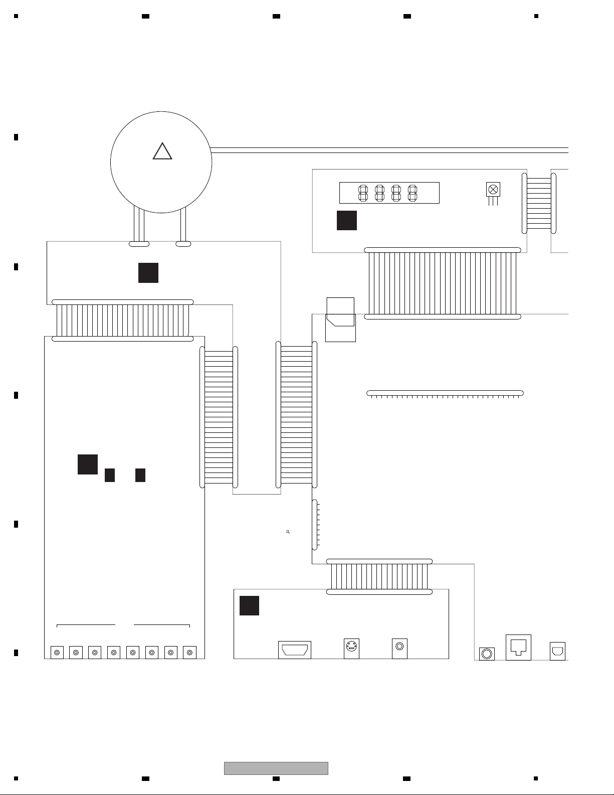
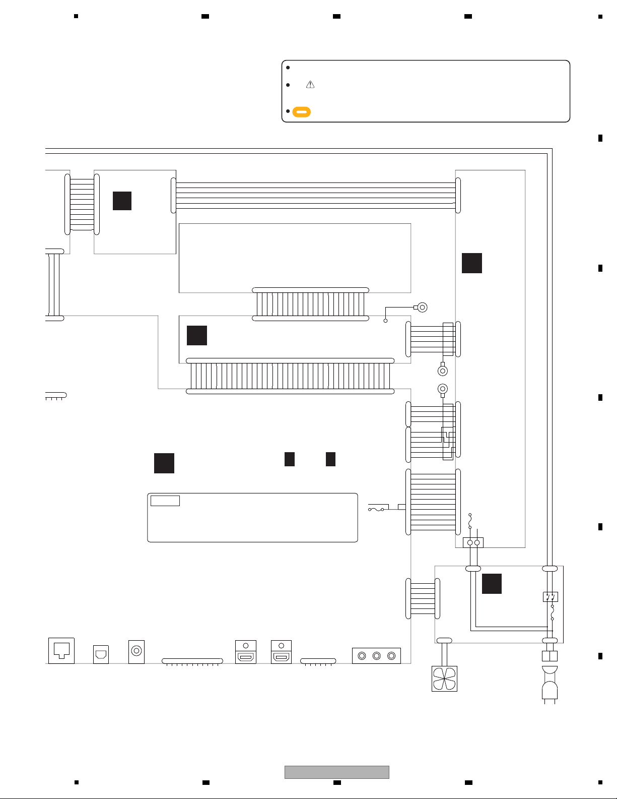
4. BLOCK DIAGRAM
4.1 OVERALL WIRING DIAGRAM
A
B
C
D
E
F
20
1
BDP-09FD
2 3 4
5
RESET#
GND
DD7
DD8
DD6
DD9
DD5
DD10
DD4
DD11
DD3
DD12
DD2
DD13
DD1
DD14
DD0
DD15
GND
KEYPIN
DMARQ
GND
DIOW#
GND
DIOR#
GND
IORDY
CSEL
DMACK#
GND
INTRQ
RESERVED
DA1
PDIAG#
DA0
DA2
CS0#
CS1#
DASP#
GND
SW+5V_W
GND
GND
SW+12V_W
V+1R8SW
P_ON
V+1R8SW
V+5SW
V+5SW
GND
V+5R8EV
GND
FL_OFF
V-8SW
GND_FAN
V+12SW
GND
LED_PON
LED_A_MODE
GND
GND
GND
GND
GND
LED_PON
KEY0
V+12
GND_LED
GND_LED
GND_FL
V-23
GND_FL
FLDC+
FLDC-
GND
RY_ON
V+12SW
GND_FAN
V+3E
FAN_V2
FAN_V1
FLDC+
FLDC-
GND_FL
V-23
GND_LED
V+12
FAN_DRIVE
GND
GND
TX+
TX-
GND
RX-
RX+
GND
+3.3V
GND
GND
GND
+3.3V
+5.0V
+5.0V
+3.3V
+5.0V
+12.0V
GND
RESERVED
GND
+12.0V
+12.0V
GND
SW+5V_W
V+2R5SW_A
V+2R5SW_B2
GND
GND
V+2R5SW_B2
GND
CN1501
VKN2050-
123456789
1011121314
15
16171819202122232425262728293031323334
35
36
373839
40
CN1601
RKN1052-
123
4
56789
10
11
1
234
CN404
VKN1818-
123456789
10111213141516171819202122232425262728293031323334
35
3637383940
CN4301
AKM1278-
1
2
3
4
5
6
7
CN404
KM200NA7
1
2
3
4
5
6
7
CN506
KM200NA2
1
2
KM200NA6L
CN302
1
2
3
4
5
6
123
CN102
AKM1359- (B TO B)
1
2
3
4
5
6
7
8
9
10
11
CN301
AKP1299- (B TO B)
1
2
3
4
5
6
7
8
9
10
11
CN7001
AKM1283-
1
2
3
4
5
6
7
8
9
10
11
12
CN202
1
2
3
4
5
6
7
8
9
10
11
12
CN201
1
2
3
4
5
6
7
8
9
10
CN204
1
2
3
4
5
6
CN401
VKN2090- (B TO B)
123456789
1011121415
16
171819
202122
13
123456789
1011121415161718192021
22
13
CN403
AKM1292-
1
2
3
4
5
6
CN203
1
2
3
4
5
6
RKN1047-A
CN9011
1
2
345
6
123
B2P3-VH
CN403
1
2
CN7003
AKM1277-
1
2
3
4
5
6
CN7004
AKM1275-
1
2
3
4
RKP1751-A
CN401
1
2
RKP1834-A
CN402
1
2
BD/DVD/CD DRIVE
AC POWER CORD
CN101
Optical Co-Axial
JA8001
DIGITAL AUDIO OUT
JA6001
JA5001
YCb/PbCr/Pr
COMPONEN T
HDMI main
GND
SH_UART1TXD
M32_UARTTXD
NC
V+3E
SCIFRXD
SCIFTXD
SH-DEBUG
V+3R3D
SATA CONNECTOR
FAN MOTOR 1
VXX3343- (For service parts number)
VKP2464-
VKN2092
AKB7102
VXM1122
AC INLET ASSY
VDA2201-
VDA2193-
SH_UART1RXD
SH_UART1CTS
SH_UART1RTS
M32_UARTRXD
V+3R3D
NC
M32TRST_N
VKN2091
PF06PP-D22
NL
LAN
HDMI sub
VKN2092
JA5501
VKP2456-
VKP2466-
PF07PP-D15
VKN2087
JA4501
JA8002
VKS1002
JTAG
GND
TDI1M
TDO1M
TCK1M
TMS1M
V+3R3PRO
ADX7723-
P7007
FU101
LN
L N
N L
VKP2465-
(KURO LINK)
JP1
VDA2205-
BDR-L04H-XA/XV/5 (Not service)
iver
ADG7061-
A
A A
SERVICE MAIN ASSY ( 1/13 - 13/13)
(VXX3348)
B
SPATA ASSY
(VWV2387)
I
SYPS ASSY
(VWR1422)
When ordering service parts, be sure to refer to "EXPLODED VIEWS and PARTS
LIST" or "PCB PARTS LIST".
The mark found on some component parts indicates the importance of the safety
factor of the part. Therefore, when replacing, be sure to use parts of identical
designation.
: The power supply is shown with the marked box.
1..SERVICE MAIN ASSY VXX3348
NSP 2..MAIN ASSY VWV2382
2..SPATA ASSY VWV2387
NOTE
ACSW ASSY
(VWG2629)
H
PSWB ASSY
(VWG2627)
G
(VXX3343)
6 7 8
A
B
C
D
E
F
BDP-09FD
5
6 7 8
21
1
C
N
1
5
0
1
PATA
IC2101
DDR2 - 0
EDE1108AC
SE- 6E- E
1Gb
IC2201
DDR2 - 0
EDE1108AC
SE- 6E- E
1Gb
IC2301
DDR2 - 0
EDE1108AC
SE- 6E- E
1Gb
IC2401
DDR2 - 0
EDE1108AC
SE- 6E- E
1Gb
IC3501
NOR FLASH
VYW2415-
1Gbits
IC3101
DDR2 - 1
EDE51 16AJ
BG- 6 E-E
512Mb
IC3202
DDR2 - 1
EDE51 16AJ
BG-6E-E
512Mb
40P
FFC
C
N
4
4
0
2
I2C
Voltage Regulator
Circuit
30P
FFC
12P
6P
10P
I2S/
Audio
Out
32b667MHz
SH Bus
CN7003
CN7001
CN1301
JTAG
forICE
VMCLK
27MHz
AMCLK1
36MHz
AMCLK2
33MHz
AMCLKf orAudio
33/36MHz
IC3801
Clock
Generator
CDCE906
11P
Bto
IC101
FL Driver
PDC182A
X4001
VSS1216-
IC4001
Sub u-com
PDC185A8
IC
Vide
ADV
(ADV73
09F
Fa
Thermo
Senser
AKM1283-
AKM1277-
VKN1322-
D
VKN2048-
32b 667MHz
6P
CN4301
CN404
CN401
C
N
4
0
2
7P
AKM127
RKP1751-
RKP1834-
X3801
VSS1226
27MHz
CN7004
AKM1275-
6P
4P
12MHz
P_ON/
FL_OFF
V101
FL
VAW1094-
C
N
3
0
2
CN301
KM200NA6L
AKP1299-
CN102
AKM1359-
Voltage
Regulator Circuit
C
N
1
0
1
VKN1290-
Serial
C
N
4
0
4
PATA
C
N
4
0
3
CN401
Voltage
Regulator
Circuit
IC401
88SA8040
SATA
VKN1818-
AKM1292-
Power Line
RC Signal
Audio Signal
Video Signal
Control & Other
VKN2090-
VKN2050-
BD Drive
BDR-L04H-XA/XV
IC1001
MAIN LSI
R8A34019BG-RF4Z-K
(SKY)
A
SERVICE MAIN ASSY
H
ACSW A
I
SYPS ASSY
G
PSWB
ASSY
F
FLKY
ASSY
B
SPATA
ASSY
BDP-09FD
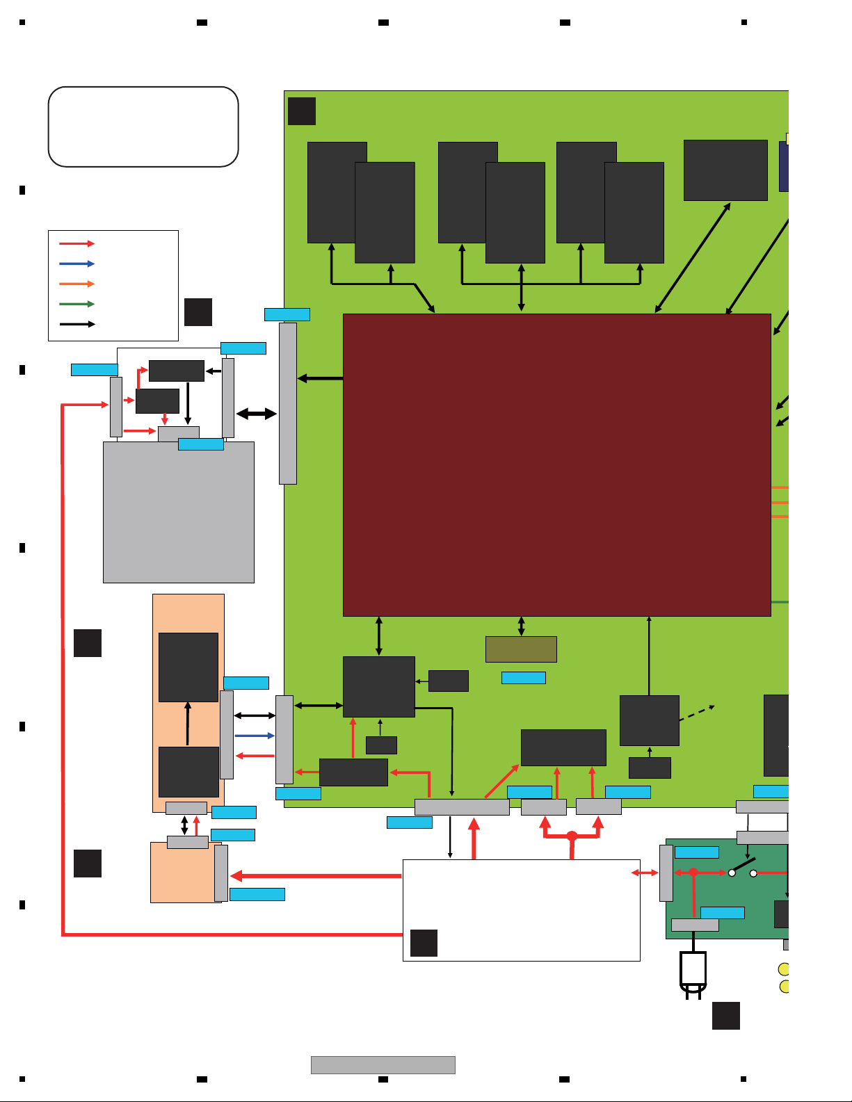
BLOCK DIAGRAM
4.2 BLOCK DIAGRAM
A
2 3 4
B
C
D
E
F
22
BDP-09FD
1
2 3 4
5
JA80
Lsb
JA30
LFE
JA201
L
JA50
Rs
JA10
R
IC602
audio DAC
WM8740
IC502
audio DAC
WM8740
IC702
audio DAC
WM8740
IC802
audio DAC
WM8740
IC202
audio DAC
WM8740
IC102
audio DAC
WM8740
IC302
audio DAC
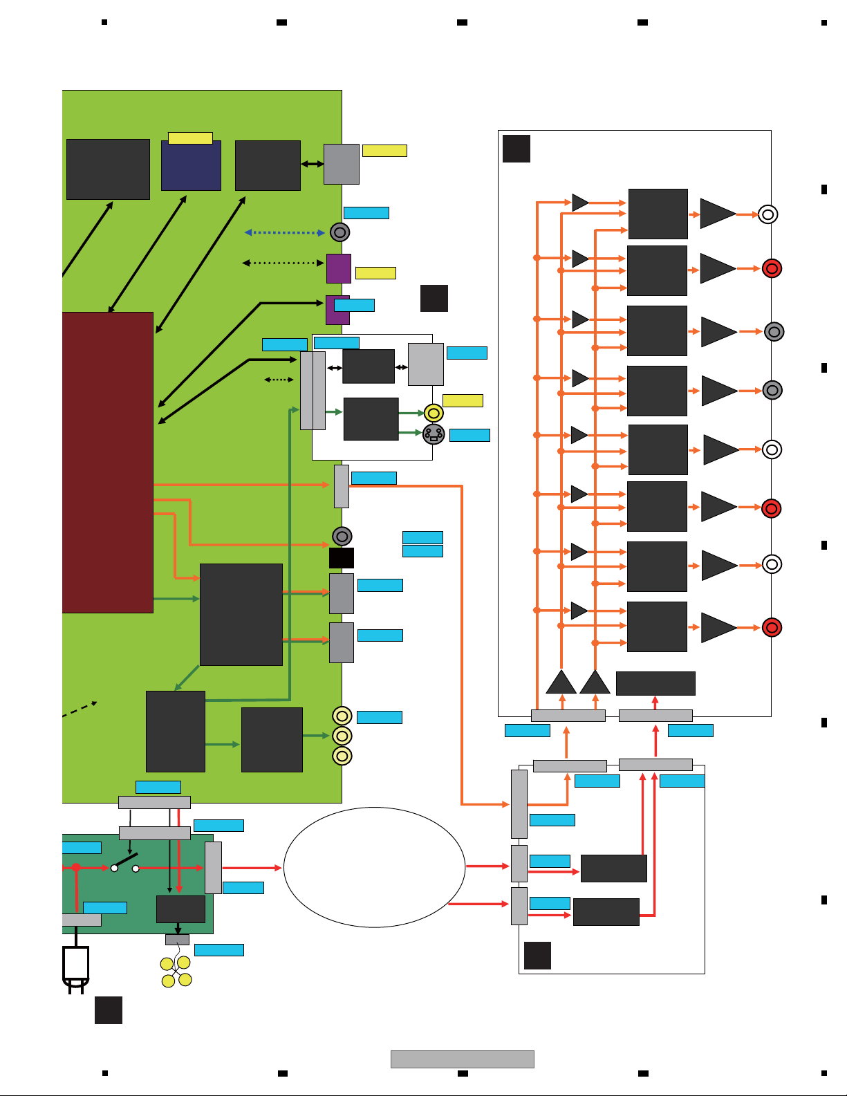
WM8740
IC402
audio DAC
WM8740
JA70
Rsb
JA60
Ls
JA4
C
IC3501
NOR FLASH
VYW2415-
1Gbits
JA8001
JA8002
SPDIF Out put
HDMI
Block
JA5001
HDMI MAI N
JA6001
Componen
t
Video
CN8901
S/ PDIF
I2S
I2S/ SPDIF
Audio
Out
JA3701
SD card
connector
SH Bus
IC6302
HD VideoAmp
ADA4412-3
AMCLKf orAudio
33/36MHz
RC
JA4501
LAN Terminal
IC4501
LAN PHY
RTL8201CP
JA5501
HDMISUB
CN506
Sub u- com
Tx/ Rx
C
N
4
0
3
SKY
Tx/ Rx
IC6301
Video ENC
ADV7344
(ADV7340 for BDP-
09FD only)
CVBS/ Y/ C
Y/ Cb / Cr
SKY
Tx/ Rx
CN1601
for
Debug
JA4351
SR
JA2300
RS232C
JA2100
CVBS
IC2302
RS232C Driver
HIN202EIBNZ
IC2100
VideoAmp
LA73054
C
N
2
0
0
0
C
N
6
0
0
1
JA2101
S- Video
HDMI
Block
Fan Control
Circuit
AKB7102
VKN20 91-
VKS1002
VKN 20 92-
VKN 2092-
DKP3748-
RKN1052
RKN1004-
AKB7102
VKN2087-
AKP1213
AKP1239
RKN1047
CN4301
CN404
CN401
7P
C
N
1
4
0
2
CN1401
CN1002
CN901
VKN1618-
VKN2008 - VKN2008-
CKS- 556
KM200NA7
AKM1278-
B2P3-VH
KM200NA2
RKP1751-
CKS- 555
CN1001
CN1301
3P
2P
2P
28PFFC
27P
CN1001
27P
Diode Rectifier
&
Smoothing Circuit
Diode Rectifier
&
Smoothing Circuit
VKN2011 -
VKN2011-
IC201
OPA2134
IC101
OPA2134
IC401
OPA2134
IC301
OPA2134
IC601
OPA2134
IC501
OPA2134
IC801
OPA2134
IC701
OPA2134
Voltage Regulator
Circuit
IC902
MMCLK
MCLK7
MCLK8
MCLK5
MCLK6
MCLK3
MCLK4
MCLK1
MCLK2
IC901
MC/MD/
ML1/ML2
LRCLK/
BCK/
ADATA0/
ADATA1/
ADATA2/
ADATA3
IC104
IC105
IC106
IC204
IC205
IC206
IC404
IC405
IC406
IC304
IC305
IC306
IC604
IC605
IC606
IC504
IC505
IC506
IC804
IC805
IC806
IC704
IC705
IC706
VKN1618-
VKN1610-
VKN1610-
CN9011
VTT1173-
SUB TRANS
D
AUJB ASSY
C
AUPW ASSY
H
ACSW ASSY
E
VOUT
ASSY
6 7 8
A
B
C
D
E
F
BDP-09FD
5
6 7 8
23
1
SW+1.8V
SW+2.5V
1
2
2
5
6
V+1R5SW
V+2R5SW_A
V+5SW
CN7004
IC7101
LP38853S
IC1001
SKY
V+1R1D
V+1R1S
V+1R1PLL
V+1R1VS
V+2R5SW_A
IC7201
S-1170B18UC-UTD
V+3R3D
V+1R8D
V+1R8S
IC4202
standby
Reset IC
IC7301
S-1172B33UC-OTS
V+3R3D
V+3R3S
V+3R3PLL
V+3R3VS
IC2601
LP2996M
IC3301
LP2996M
IC2151
S-1170B18UC-OTD
V+1R8ch0-1
IC2101
K4T51083QC
DDR2
IC2201
K4T51083QC
DDR2
DDR_PSW
IC2351
S-1170B18UC-OTD
V+1R8ch0-2
IC2301
K4T51083QC
DDR2
IC2401
K4T51083QC
DDR2
DDR_PSW
IC3151
S-1170B18UC-OTD
V+1R8ch1-1
IC3101
K4T51163QC
DDR2
IC3201
K4T51163QC
DDR2
DDR_PSW
V+3R3FM
IC3551
TC7SH08FUS1
IC6301
ADV7344BSTZ
VideoEncoder
IC7311
S-1170B33UC-OTS
V+3R3VA
IC3501
S29GL512N10TFI020
Flash
V+3R3CG
IC3801
CDCE906PWR
Clock Gen.
IC3831
standby
IC3841
standby
IC8001
ICS571MLF
0 Delay Buffa
IC8011
TC7WH74FU
V+3R3SPDIF
IC7331
S-1170B18UC-OTD
V+3R3VD
V+1R8VD
IC7771
PQ035ZN1HZPH
IC7711
S-1170B33UC-OTS
V+1R2H
V+2R5F
IC4203
standby
Reset IC
4
JA3701
to SD Card
IC1621
standby
CN7001
7
8
3
CN201
SW+1.8V
SW+2.5V
4
5
CN202
SW+5V
IC4201
BU4809F
Reset IC
IC9002
IC9504
Marvell
88DE2710
VideoFormat
Conv.
IC5009
MN864707KT
HDMI
IC9011
XCF16PV0G48C
PROM
IC5006
ICS571MLF
0 Delay Buffa
IC4501
LAN
RTL8201CP
IC7731
S-1170B25UC-OTK
IC7651
S-1155B12-U5T1
IC7621
S-1170B33UC-OTS
200mA
IC9301
EDE5116AJBG-
6E-E-K
DDR2
IC9302
EDE5116AJBG-
6E-E-K
DDR2
IC7751
S-1172B18-E6T1
IC9505
HY5DU561622F
TP-D43
DDR1
IC9506
HY5DU561622F
TP-D43
DDR1
IC7851
S-1172B12-E6T1
IC7801
S-1170B33UC-OTS
IC7831
S-1172B26-E6T1
IC7901
S-1170B33UC-OTS
Q501
Chop.
IC
DDR_PSW
V+3D
V+3R3MV
V+3R3MV
V+2R5_MV
V+2R5MVDDR_1, _2
V+2R5_MV
V+1R2_MV
V+1R2MV_1
V+3R3HD1
V+1R2HD
V+3R3HD1_D
V+1R2HD1_D
V+3R3FP
V+1R8PR1
V+1R8FP
V+3R3FP1
V+3R3PR1
Q301
IC350(1/2)
V+3R3LAN
IC6304
TC74VHC157FTS1
IC9008
BU4228G
V+3R3FP1
X9001
BU4228G
IC9303
NJM10904V
V+2R5FP1
JA8002
VKS1002
CN1301
1
2
V+3R3D
SH_JTAG
5
R1441
R1442
L1431
DTL1106
-
L1401
DTL1106
-
R1401
R1402
L2101
DTL1106
-
DTL1106
-
DTL1106
-
L2301
L2601,L3301
L3102
DTL1106
-
L9009
CTF1394-
L9501
VTL1171-
R9501 0
R9502 0
V+2R5MVDDR
L6303
IC8101
TC7WZU74FU
L8001
L8002
L8003
L8120
D7832
D7852
2
1
V+2R5SW_B2
CN7003
I
SYPS ASSY
A
SERVICE MAIN ASSY
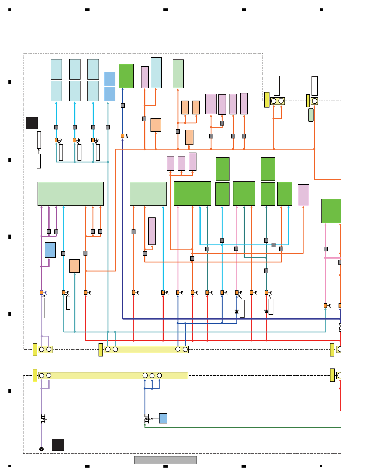
4.3 POWER BLOCK DIAGRAM
A
2 3 4
B
C
D
E
F
24
1
BDP-09FD
2 3 4
SW+5V
EV+6V
SW+12V
SW-23V
8
4
11
V+5SW
V+5R8E
V+12SW
Chop.
IC
3
4
JA3701
to SD Card
14
CN4401
CN7001
IC7001
S-1170B33UC-OTS
V+3R3E
IC4001
LC87F5932A
SUB microcomputer
IC4351
TC7SH08FUS1
V+3SE
IC4002
BU45282G
CN1601
11
SH Debug
CN4201
1
IC7601
S-1132B50-U5-TRB
IC7501
S-L2980A50MC-C7J
V+5E
26
14
CN101
V+3R3SW
V+3R3D
26
5
1
V+5E
LED×7
8
CN102
CN301
LED×1
V+12
V-23V
IC1
RPM7140-H4
IC7421
S-1170B50UC-OUJ
V+5SW
V+5AD_V
Video Buffer
Circuit ×3
V1
VAW1094-
FL
V+5E
5
8
4
11
CN202
P101
P201
Q201
SW-23V
SW+12V
5
1
CN203
SW+12V(W)
SW+5V(W)
EV+6V
SW+5V
Drive
1
5
SW+12V(W)
SW+5V(W)
CN401
CN8901
IC5009
MN864707KT
HDMI
5
1
SW-8V
IC5509
MN864707KT
HDMI
JA5501
HDMI
ICS571MLF
0 Delay Buffa
JA5001
HDMI
IC7332
NJM79M05DL1
IC2
LC876D16A
FL Driver
IC7651
S-1155B12-U5T1
IC7621
S-1170B33UC-OTS
200mA
6
1.5mA
IC2100
LA73054
Video Driver
5
RY402
ASR7013-
RELAY
21mA
5
IC6001
ADA4412-3
Video Drver
SW+12V
for Video
RY401
ASR7013-
RELAY
21mA
V-5AD_V
FAN
Circuit
Rear Side
40 ~ 100mA
Video Buffer
Circuit ×3
11
10
Q602
Q702
4
3
CN204
FLDC+
FLDC-
V-8SW
V+5HDE
V+3R3HD1
V+1R2HD
V+3R3HD1_D
V+3R3HD1_A
V+1R2HD1_D
IC2302
RS-232C
HIN202EIBNZ
2
19
V+5E
4
3
V+3R3SE
29
Tact Switch
V+3E
29
FLDC+
FLDC-
8 4
4
11
10
11 10
CN302
IC350(2/2)
Q401
P601
IC801
CN404
CN4301
3 3
FAN
Circuit
inside
V+12
V+3E
V+12SW
CN2000
V+5AD_V
CN6001
4
V+3R3E
17
IC2300
TC7SH32FUS1
IC2301
standby
V+3E
V-23V
V+5E
Sub Debug
V+12SW
IC5001
TC7MBL6353SFK
V+3R3FP1
V+5E
V-8SW
5
6
to AUPW
L4411
L4407
L4421
1.5A
0.63A
0.63A
V+1R2HD2_D
V+3R3HD2_D
V+3R3HD2_A
6
6
CN403
IC401
88SA8040
SPATA
20
14
8
+3.3V
+1.8V
+12.0V
+5.0V
IC403
PQ070XZ02ZP
IC402
S-1132B18
IC404
BU4228FVE
L4303
L4305
V+5SW_2
IC7611
S-1170B33UC-OTS
V+3R3HD2
P7007
R702 1
R651 0.22
R851 1
to FLKB
from SYPS
10
9
15
16
21
22
+3.3V
+5.0V
+12.0V
F
FLKY ASSY
E
VOUT ASSY
B
SPATA ASSY
ACSW ASSY
H
PSWB ASSY
G
5
6 7 8
A
B
C
D
E
BDP-09FD
F
25
6 7 8
5
1
CN1002
CN1001
2
V+5E
CN901
AUDIO_1
AUDIO_2
TOROIDALCORE-
TRANS
DIGITAL_1
8
V+
14
V+3.
V+
V-9
V-9
14
GND
IC1001
S-1170B33UC-O
IC1002
S-1170B33UC-O
IC1004
S-1170B33UC-O
IC1003
S-1170B33UC-O
IC1015
NJM78M05DL1
IC1016
NJM78M05DL1
IC1013
NJM78M05DL1
IC1014
NJM78M05DL1
IC1004
NJM78M12D
IC1005
NJM78M12DL
IC1006
NJM78M12DL
IC1007
NJM78M12DL
IC1008
NJM79M12DL
IC1009
NJM79M12DL1
IC1010
NJM79M12DL
IC1011
NJM79M12DL
CN1001
CN1301
1
2
2
1
15
16
15
16
14
3
2
4
8
13
22
23
24
25
9
10
9
10
2
3
4
unreg17V_DAC
unreg17V
unreg-17V
unreg+5V
CN1402
26
2
CN1401
V+5E
Q1302
22
23
24
25
from MAIN
V+5E
DIGITAL_2
unreg-17V
unreg17V
unreg17V_DAC
ureg5V
L1003
D1301
D1101
D1201
D1102
D1202
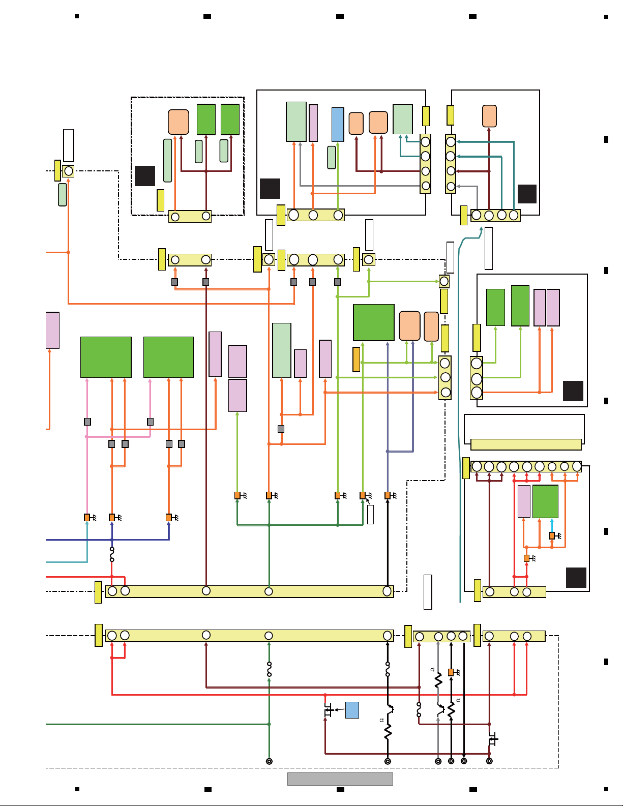
C
AUPW ASSY
D
AUJB ASSY
2 3 4
A
B
C
D
E
F
26
BDP-09FD
1
2 3 4
5
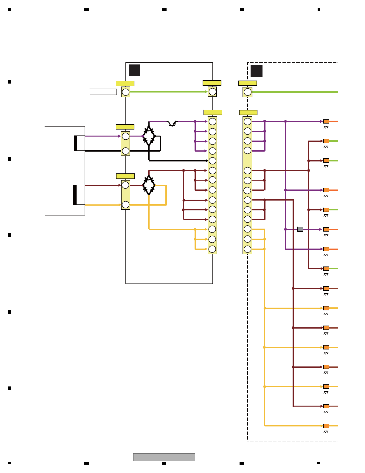
MUTE
Circuit
IC102
WM8740SEDS
DAC
V+3.3D_1
IC202
WM8740SEDS
DAC
IC302
WM8740SEDS
DAC
IC402
WM8740SEDS
DAC
V+3.3D_4
IC502
WM8740SEDS
DAC
IC602
WM8740SEDS
DAC
V+5A
V+5A
V+5A
V+5A
IC101
OPA2134PA
V+9A
V+9A
V+3.3D_2
IC702
WM8740SEDS
DAC
IC802
WM8740SEDS
DAC
V+3.3D_3
V-9A
V-9A
V-9A
V-9A
V+9A
V+9A
IC104
TC7SH32FUS1
IC105
TC7SH32FUS1
IC106
TC7SH32FUS1
IC204
TC7SH32FUS1
IC205
TC7SH32FUS1
IC206
TC7SH32FUS1
IC303
ICS571MLF
0 Delay Buffa
IC403
ICS571MLF
0 Delay Buffa
IC304
TC7SH32FUS1
IC305
TC7SH32FUS1
IC306
TC7SH32FUS1
IC404
TC7SH32FUS1
IC405
TC7SH32FUS1
IC406
TC7SH32FUS1
IC503
ICS571MLF
0 Delay Buffa
IC603
ICS571MLF
0 Delay Buffa
IC504
TC7SH32FUS1
IC505
TC7SH32FUS1
IC506
TC7SH32FUS1
IC604
TC7SH32FUS1
IC605
TC7SH32FUS1
IC606
TC7SH32FUS1
IC704
TC7SH32FUS1
IC705
TC7SH32FUS1
IC706
TC7SH32FUS1
IC804
TC7SH32FUS1
IC805
TC7SH32FUS1
IC806
TC7SH32FUS1
IC201
OPA2134PA
IC301
OPA2134PA
IC401
OPA2134PA
IC501
OPA2134PA
IC601
OPA2134PA
IC701
OPA2134PA
IC801
OPA2134PA
V+MUTE
IC1001
S-1170B33UC-OTS
IC1002
S-1170B33UC-OTS
IC1004
S-1170B33UC-OTS
IC1003
S-1170B33UC-OTS
IC1015
NJM78M05DL1A
IC1016
NJM78M05DL1A
IC1013
NJM78M05DL1A
IC1014
NJM78M05DL1A
IC1004
NJM78M12DL1A
IC1005
NJM78M12DL1A
IC1006
NJM78M12DL1A
IC1007
NJM78M12DL1A
IC1008
NJM79M12DL1A
IC1009
NJM79M12DL1A
IC1010
NJM79M12DL1A
IC1011
NJM79M12DL1A
IC902
TC74VHC04FTS1
L802
L702
L905
L703
L803
L102
L103
L203
L202
L502
L602
L501
L601
L503
L603
6 7 8
A
B
C
D
5
BDP-09FD
6 7 8
E
F
27
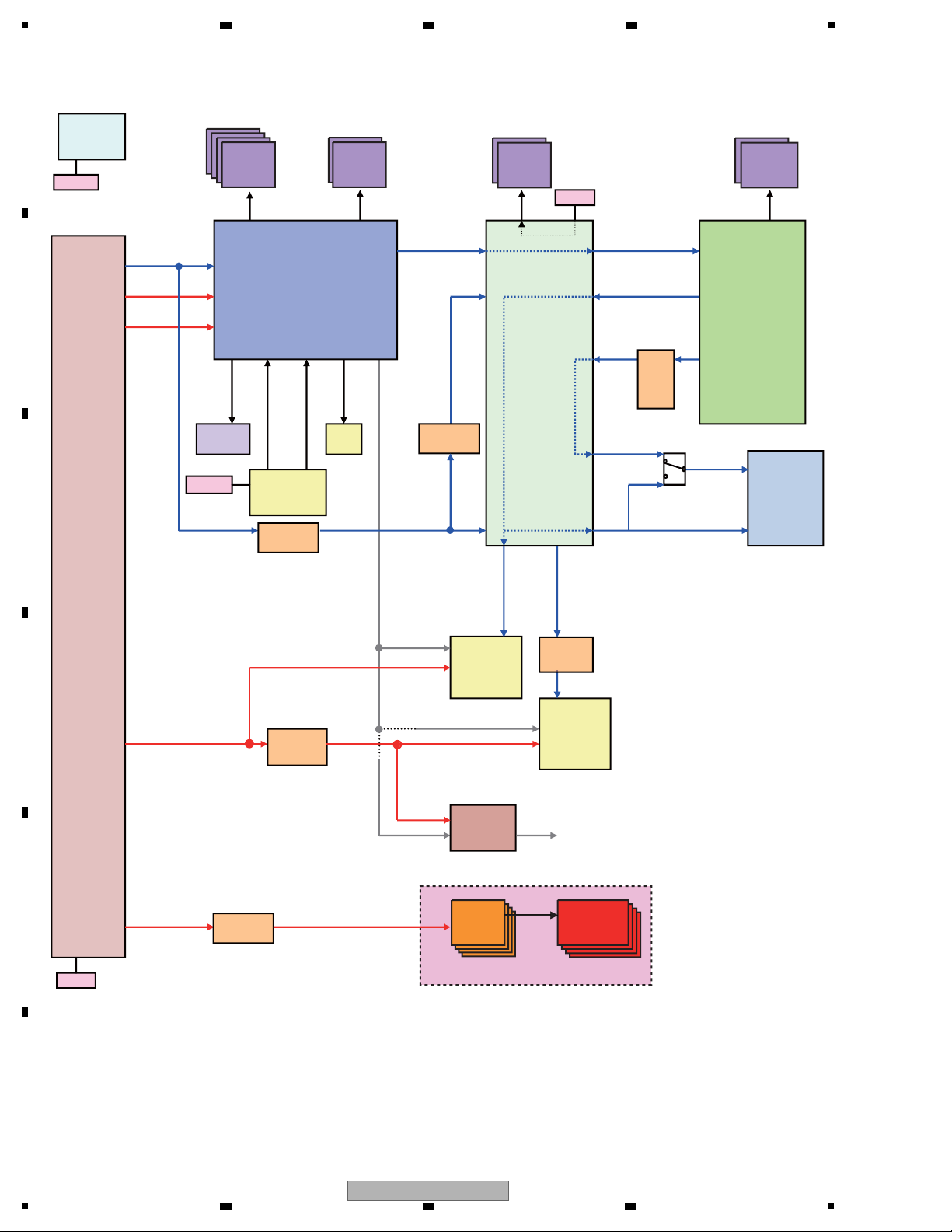
1
AL24
PXPCLK
AF14
OM_CLK
11
VMCLK_SKY
AE31 27/74MHz C17 27/74MHz
C5
27MHz
15
AMCLK2
AF33 AM17
VMCLK
AE13
A13
IMP_CLK
33MHz
27MHz 27/74/148MHz
D18
16
AMCLK1
AG33
36MHz
V4
C13
A12
V31
AJ24
AD13
IMA_CLK2
SDCLK
24.75
MHz
ETX_CLK
25MHz
ERX_CLK
25MHz
AT1DMACK
33MHz
SPDIF
27MHz
B15
HD
N24 27MHz
SDPXCLK
30
SD
B14
F23
PXCLK_ADV7340
AB24 AB25 27/74MHz
63
At 148 MHz, both clock signal and
data are muted.
20
33/36MHz
COAX/OPT
19
33/36MHz 33/36MHz
27MHz
IC9002
IC9504
88DE2710-K
Marvell
IC6301
ADV7344
/ADV7340
HDMI Tx
(MAIN)
IC8101
TC7WH04FU
Ceramic
IC4001
Subcom
IC1001
R8A34019BG
SKY
IC3801
CDCE
906PWR
Crystal
IC8001
ICS571
HDMI Tx
(Sub)
IC5006
ICS571
SD Card
ATA
IC4501
RTL9201
LAN
IC9004
TC7PA04FU
Crystal
HDMI_CLK1
HDMI_CLK2
27/74/148MHz
27/74/148MHz
IC9004
TC7PA
04FU
X3801
VSS1226
X4001
VSS1216
X4501
VSS1215
16
7
X9001
VSS1225
IC8031
TC7SZ32FU
IC3802
TC7SZ32FU
DDR2
1G x4
DDR
256M x2
DDR2
512M
x2
DDR2
512M
x2
IC3101
IC3202
IC2101
IC2201
IC2301
IC2401
IC9301
IC9302
IC9505
IC9506
AudioDAC
x8
ICS571
x8
Audio PCB
Crystal
4.4 CLOCK BLOCK DIAGRAM
A
2 3 4
B
C
D
E
F
28
BDP-09FD
1
2 3 4
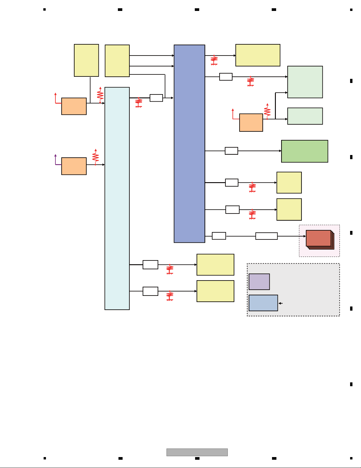
5
A low section of 200 µs or
longer is required.
Power-on reset built in
Software reset is available.
Audio PCB
I
C9002
IC9504
88DE2710-K
ADV7340
HDMI Tx
(MAIN)
AudioDACAudioDAC
x8x8
IC4001
PDC165A8
SubCON
IC1001
R8A34019BG
SKY
HDMI
Tx
(Sub)
SD Card
CN1501
ATA
CONNECTOR
LAN
IC4501
RTL8201CP
22Ω
CN1301
ICE
CONNECTOR
IC4002
BD45282G
CN4201
Subcom
DeBug
CONNECTOR
IC9011
PROM
Resetting not required
IC4201
BU4809F
IC9008
BU4228G
100 Ω
22 Ω
22Ω
CTF1306
220 Ω
RESET3#
MRVL_XRST
HDMI1_XRST
HDMI2_XRST
ADAC_XRST
AT1RESET
42
1
AB15
A12
IC9002_XRST
C16
D3
C17
A1
A3
AL33
W29
AG30
AD33
M32TRST_N
SH_TRST_N
RESET_SKY#
14
12
53
50
6
CFM
SW+3.3V
22Ω
RESET_N
SKY core voltage detection
SW+1.1V
EV+3.3V
SCON_
XRESET
AL16
47 Ω
IC3501
FLASH ROM
100 Ω
RESET2#
14
14
AudioDAC
x8
4.5 RESET BLOCK DIAGRAM
6 7 8
A
B
C
D
E
F
BDP-09FD
5
6 7 8
29
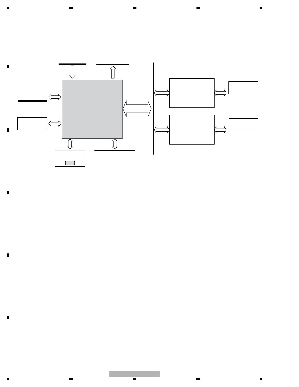
1
From IC1001
to IC6301
(for AnalogVideo)
from,to IC9301,IC9302
NSP
IC9002
Video Processor
IC9011
PE9018A8-K
from,to IC9504
IC5009
MN864707KT
HDMI
Transmitter
IC5509
MN864707KT
HDMI
Transmitter
JA5001
VKN2092-A
JA5501
VKN2092-A
HDMI Connector
MAIN
HDMI Connector
SUB
CN9011
VKN2092-A
Digital video signals from IC1001 are processed at IC9002 and IC9504 then output to IC5009, IC5509, and IC6301. If only either an
HDMI or analog video signal is output, check the reset and clock signals from around the relevant IC:
No HDMI MAIN video output available: Relevant IC: IC5009
No HDMI SUB video output available: Relevant IC: IC5509
No analog video output available: Relevant IC: IC6301
If no video signal is output, check the reset and clock signals from around IC9002 and IC9504.
4.6 VIDEO BLOCK DIAGRAM
A
2 3 4
B
C
D
E
F
30
1
2 3 4
BDP-09FD
 Loading...