

Page 1
ENGLISH
Français
English
Français
English
Français
Deutsch
English
Français
Deutsch
English
Français
Deutsch
Italiano
English
Français
Deutsch
Italiano
Nederlands
Español
English
Français
Deutsch
Italiano
English
BCS-SB616
XV-BD515FSW
S-BD616SB
S-BD707SW
BCS-FS515
XV-BD515FSW
S-BD515FS
FRANÇAIS
DEUTSCH ITALIANO ESPAÑOL
NEDERLANDS
P/NO: MFL67205103
Page 2
Getting Started2
Safety Information
1
Getting Started
CAUTION: TO REDUCE THE RISK OF ELECTRIC
SHOCK DO NOT REMOVE COVER (OR BACK) NO
USER-SERVICEABLE PARTS INSIDE REFER SERVICING
TO QUALIFIED SERVICE PERSONNEL.
enclosure that may be of sucient magnitude to
constitute a risk of electric shock to persons.
instructions in the literature accompanying the
product.
WARNING: TO PREVENT FIRE OR ELECTRIC SHOCK
HAZARD, DO NOT EXPOSE THIS PRODUCT TO RAIN
OR MOISTURE.
VENTILATION CAUTION: When installing this
unit, make sure to leave space around the unit for
ventilation to improve heat radiation (at least 10 cm
at top, 10 cm at rear, and 10 cm at each side).
WARNING: Slots and openings in the cabinet are
provided for ventilation to ensure reliable operation
of the product, and to protect it from overheating.
To prevent re hazard, the openings should
never be blocked or covered with items (such as
newspapers, table-cloths, curtains) or by operating
the equipment on thick carpet or a bed.
Operating Environment: Operating environment
temperature and humidity: +5 °C to +35 °C (+41
°F to +95 °F); less than 85 %RH (cooling vents not
blocked)
Do not install this unit in a poorly ventilated area,
or in locations exposed to high humidity or direct
sunlight (or strong articial light)
CAUTION
RISK OF ELECTRIC SHOCK
DO NOT OPEN
This lightning ash with arrowhead
symbol within an equilateral triangle
is intended to alert the user to the
presence of uninsulated dangerous
voltage within the product’s
The exclamation point within an
equilateral triangle is intended
to alert the user to the presence
of important operating and
maintenance (servicing)
CAUTION: This product is a class 1 laser product
classied under the Safety of laser products,
IEC60825-1:2007. To ensure proper use of this
product, please read this owner’s manual carefully
and retain it for future reference. Shall the unit
require maintenance, contact an authorized service
center.
Use of controls, adjustments or the performance of
procedures other than those specied herein may
result in hazardous radiation exposure.
To prevent direct exposure to laser beam, do not try
to open the enclosure. Visible laser radiation when
open. DO NOT STARE INTO BEAM.
CAUTION concerning the Power Cord
Most appliances recommend they be placed upon
a dedicated circuit;
That is, a single outlet circuit which powers only
that appliance and has no additional outlets or
branch circuits. Check the specication page of this
owner’s manual to be certain. Do not overload wall
outlets. Overloaded wall outlets, loose or damaged
wall outlets, extension cords, frayed power cords, or
damaged or cracked wire insulation are dangerous.
Any of these conditions could result in electric
shock or re. Periodically examine the cord of your
appliance, and if its appearance indicates damage
or deterioration, unplug it, discontinue use of the
appliance, and have the cord replaced with an
exact replacement part by an authorized service
center. Protect the power cord from physical or
mechanical abuse, such as being twisted, kinked,
pinched, closed in a door, or walked upon. Pay
particular attention to plugs, wall outlets, and
the point where the cord exits the appliance. To
disconnect power from the mains, pull out the
mains cord plug. When installing the product,
ensure that the plug is easily accessible.
Page 3

Getting Started 3
This device is equipped with a portable battery or
accumulator.
Safety way to remove the battery or the
battery from the equipment: Remove the
old battery or battery pack, follow the steps
in reverse order than the assembly. To prevent
contamination of the environment and bring on
possible threat to human and animal health, the
old battery or the battery put it in the appropriate
container at designated collection points. Do
not dispose of batteries or battery together with
other waste. It is recommended that you use
local, free reimbursement systems batteries and
accumulators. The battery shall not be exposed to
excessive heat such as sunshine, re or the like.
CAUTION:
yDo not use or store batteries in direct sunlight or
other excessively hot place, such as inside a car
or near a heater. This can cause batteries to leak,
overheat, explode or catch re. It can also reduce
the life or performance of batteries.
yWhen disposing of used batteries, please comply
with governmental regulations or environmental
public instruction's rules that apply in your
country or area.
CAUTION: The apparatus shall not be exposed to
water (dripping or splashing) and no objects lled
with liquids, such as vases, shall be placed on the
apparatus.
Information for users on collection and disposal
of old equipment and used batteries
Pb
Symbol examples
for batteries
These symbols on the products, packaging, and/
or accompanying documents mean that used
electrical and electronic products and batteries
should not be mixed with general household
waste.
For proper treatment, recovery and recycling of
old products and used batteries, please take them
to applicable collection points in accordance with
your national legislation.
By disposing of these products and batteries
correctly, you will help to save valuable resources
and prevent any potential negative eects on
human health and the environment which could
otherwise arise from inappropriate waste handling.
For more information about collection and
recycling of old products and batteries, please
contact your local municipality, your waste disposal
service or the point of sale where you purchased
the items.
These symbols are only valid in the European
Union.
For countries outside the European Union:
If you wish to discard these items, please contact
your local authorities or dealer and ask for the
correct method of disposal.
1
Getting Started
Page 4

Getting Started4
For Wireless product European Union Notice
PIONEER hereby declares that
this/these product(s) is/are in
1
requirements and other relevant provisions of
Getting Started
Directive 1999/5/EC, 2004/108/EC, 2006/95/EC
and 2009/125/EC.
Indoor Use Only
RF Radiation Exposure Statement
This equipment should be installed and operated
with minimum distance 20 cm between the
radiator and your body.
WARNING: To prevent a re hazard, do not place
any naked ame sources (such as a lighted candle)
on the equipment.
WARNING: Before plugging in for the rst time, read
the following section carefully.
The voltage of the available power supply
diers according to country or region. Be sure
that the power supply voltage of the area
where this unit will be used meets the required
voltage (e.g., 230 V or 120 V) written on the rear
panel.
CAUTION: The 1 STANDBY/ON switch on this
unit will not completely shut o all power from
the AC outlet. Since the power cord serves as
the main disconnect device for the unit, you will
need to unplug it from the AC outlet to shut
down all power. Therefore, make sure the unit
has been installed so that the power cord can be
easily unplugged from the AC outlet in case of
an accident. To avoid re hazard, the power cord
should also be unplugged from the AC outlet when
left unused for a long period of time (for example,
when on vacation).
CAUTION: This product is for general household
purposes. Any failure due to use for other than
household purposes (such as long-term use for
business purposes in a restaurant or use in a car or
ship) and which requires repair will be charged for
even during the warranty period.
compliance with the essential
Notes on Copyrights
yBecause AACS (Advanced Access Content
System) is approved as content protection
system for Blu-ray Disc format, similar to use of
CSS (Content Scramble System) for DVD format,
certain restrictions are imposed on playback,
analog signal output, etc., of AACS protected
contents. The operation of this product and
restrictions on this product may vary depending
on your time of purchase as those restrictions
may be adopted and/or changed by AACS after
the production of this product.
yFurthermore, BD-ROM Mark and BD+ are
additionally used as content protection systems
for Blu-ray Disc format, which imposes certain
restrictions including playback restrictions for
BD-ROM Mark and/or BD+ protected contents.
To obtain additional information on AACS, BDROM Mark, BD+, or this product, please contact
an authorized Customer Service Center.
yMany BD-ROM/DVD discs are encoded with
copy protection. Because of this, you should only
connect your player directly to your TV, not to a
VCR. Connecting to a VCR results in a distorted
picture from copy-protected discs.
yThis item incorporates copy protection
technology that is protected by U.S. patents
and other intellectual property rights of
Rovi Corporation. Reverse engineering and
disassembly are prohibited.
yUnder the U.S. Copyright laws and Copyright
laws of other countries, unauthorized recording,
use, display, distribution, or revision of television
programs, videotapes, BD-ROM discs, DVDs, CDs
and other materials may subject you to civil and/
or criminal liability.
Page 5

Important Notice for TV colour
system
The colour system of this player diers according to
currently playing discs.
For example, when the player plays the disc
recorded in the NTSC colour system, the image is
output as an NTSC signal.
Only the multi system colour TV can receive all
signals output from the player.
yIf you have a PAL colour system TV, you will see
just distorted images when using discs or video
contents recorded in NTSC.
yThe multi system colour TV changes the colour
system automatically according to input signals.
In case that the colour system is not changed
automatically, turn it o and then on to see
normal images on screen.
yEven if the disc recorded in NTSC colour system
are well displayed on your TV, these may not be
recorded correctly on your recorder.
Getting Started 5
1
Getting Started
Page 6

Table of Contents6
Table of Contents
1 Getting Started
2 Safety Information
8 Introduction
8 – Playable Discs and symbols used in
this manual
9 – About the “7” Symbol Display
10 – Supplied Accessories
10 – Accessories of speaker box
(S-BD616SB)
10 – Accessories of speaker box
(S-BD707SW)
10 – Accessories of speaker box
(S-BD515FS)
11 – File compatibility
12 – AVCHD (Advanced Video Codec High
Definition)
12 – About DLNA
13 – Certain System Requirements
13 – Regional Code
13 – Compatibility Notes
14 Remote control
15 Front panel
15 Rear panel
26 – ARC (Audio Return Channel) function
27 – Component Video Connection
27 – Video Connection
28 – Resolution Setting
28 Antenna connection
29 Connections with external device
29 – AUX Connection
29 – PORTABLE IN connection
30 – OPTICAL IN connection
30 – HDMI IN 1/2 connection
31 Connecting to your Home Network
31 – Wired network connection
32 – Wired Network Setup
33 – Wireless Network Connection
33 – Wireless Network Setup
36 USB device connection
36 – Playback content in the USB device
3 System Setting
37 Settings
37 – Adjust the Setup Settings
37 – [DISPLAY] Menu
39 – [LANGUAGE] Menu
39 – [AUDIO] Menu
40 – [LOCK] Menu
41 – [NETWORK] Menu
42 – [OTHERS] Menu
43 Sound Effect
2 Connecting
16 Assemble the speakers
16 – Speaker Setup for BCS-SB616
18 – Wall mounting the speaker for
BCS-SB616
19 – Additional notes on speaker
placement for BCS-SB616
19 – Positioning the system for
BCS-SB616
20 – Speaker Setup for BCS-FS515
23 – Wall mounting the speakers for
BCS-FS515
24 – Additional notes on speaker
placement for BCS-FS515
24 – Positioning the system for BCS-FS515
25 Connecting to Your TV
25 – HDMI Connection
4 Operating
44 General Playback
44 – Using [HOME] menu
44 – Playing a Disc
44 – Playing a file on a disc/USB device
45 – Playing Blu-ray 3D disc
45 – Enjoying BD-Live™
46 – Playing a file on a network server
47 – Basic operations for video and audio
content
47 – Basic operations for photo content
47 – Using the disc menu
48 – Resume playback
49 Advanced Playback
49 – Repeat Playback
49 – Repeating a specific portion
Page 7

Table of Contents 7
49 – Enlarge the playback image
50 – Marker Search
50 – Using the search menu
51 – Selecting a subtitle file
51 – Last Scene Memory
52 – Options while viewing a photo
52 – Listening to music while slide show
53 On-Screen display
53 – Displaying content information on-
screen
54 – Playing from selected time
54 – Hearing a different audio
54 – Selecting a subtitle language
54 – Watching from a different angle
55 – Changing the TV Aspect Ratio
55 – Changing subtitle code page
55 – Changing the Picture Mode
56 Audio CD Recording
57 Playing the iPod
57 – Enjoying iPod on the screen
58 – Enjoying the iPod IN mode
59 Radio Operations
59 – Presetting the Radio Stations
59 – Deleting a saved station
59 – Deleting all the saved stations
59 – Improving poor FM reception
59 – See information about a radio station
60 Using the Online
5 Troubleshooting
61 Troubleshooting
61 – General
62 – Network
63 – Picture
63 – Sound
63 – Updates
69 Video Output Resolution
70 Specifications
72 Maintenance
72 – Handling the Unit
72 – Notes on Discs
73 Important Information Relating to
Network Services
73 Software License Notice
1
2
3
4
5
6
6 Appendix
64 Controlling a TV with the Supplied
Remote Control
64 – Setting up the remote to control your
TV
65 Area Code List
66 Language code List
67 Trademarks and Licenses
Page 8

Getting Started8
Introduction
1
Playable Discs and symbols used in this manual
Getting Started
Media/Term Logo Symbol Description
yDiscs such as movies that can be purchased or
rented.
y“Blu-ray 3D” discs
yBD-R/RE discs that are recorded in BDAV format.
yBD-R/RE discs that contain Movie, Music or
Photo les.
yISO 9660+JOLIET, UDF and UDF Bridge format
yDiscs such as movies that can be purchased or
rented.
yVideo mode and nalized only
ySupports the dual layer disc also
Finalized AVCHD format
yDVD±R/RW discs that contain Movie, Music or
Photo les.
yISO 9660+JOLIET, UDF and UDF Bridge format
Blu-ray
DVD-ROM
DVD-R
DVD-RW
DVD+R
DVD+RW
(8 cm /
12 cm)
e
y
u
i
r
o
y
u
i
DVD-RW
(VR)
(8 cm /
12 cm)
Audio CD
(8 cm /
12 cm)
CD-R/RW
(8 cm /
12 cm)
Note –
Caution –
r
t
y
u
i
,
>
VR mode and nalized only
Audio CD
yCD-R/RW discs that contain Movie, Music or
Photo les.
yISO 9660+JOLIET, UDF and UDF Bridge format
Indicates special notes and operating features.
Indicates cautions for preventing possible
damages from abuse.
Page 9

Note
,
yDepending on the conditions of the
recording equipment or the CD-R/RW (or
DVD±R/RW) disc itself, some CD-R/RW (or
DVD±R/RW) discs cannot be played on the
unit.
yDepending on the recording software & the
nalization, some recorded discs (CD-R/RW,
DVD±R/RW, BD-R/RE) may not be playable.
yBD-R/RE, DVD±R/RW and CD-R/RW discs
recorded using a personal computer or a
DVD or CD Recorder may not play if the
disc is damaged or dirty, or if there is dirt or
condensation on the player’s lens.
yIf you record a disc using a personal
computer, even if it is recorded in a
compatible format, there are cases in which
it may not play because of the settings of
the application software used to create the
disc. (Check with the software publisher for
more detailed information.)
yThis player requires discs and recordings to
meet certain technical standards in order to
achieve optimal playback quality.
yPre-recorded DVDs are automatically set to
these standards. There are many dierent
types of recordable disc formats (including
CD-R containing MP3 or WMA les) and
these require certain pre-existing conditions
to ensure compatible playback.
yCustomers should note that permission
is required in order to download MP3 /
WMA les and music from the Internet.
Our company has no right to grant such
permission. Permission should always be
sought from the copyright owner.
yYou have to set the disc format option
to [Mastered] in order to make the
discs compatible with the players when
formatting rewritable discs. When setting
the option to Live File System, you cannot
use it on the player. (Mastered/Live File
System : Disc format system for Windows
Vista® and Windows 7®)
yBDXL cannot be supported.
Getting Started 9
About the “7” Symbol Display
“7” may appear on your TV display during
operation and indicates that the function explained
in this owner’s manual is not available on that
specic media.
1
Getting Started
Page 10
Getting Started10
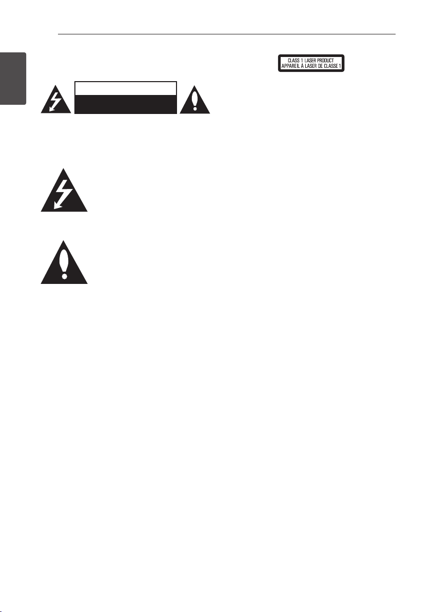
Supplied Accessories
1
Getting Started
Video cable (1) Remote control (1)
Battery (1)
iPod cradle (1)
Accessories of speaker box
(S-BD616SB)
FM antenna (1)
Accessories of speaker box
(S-BD707SW)
Speaker cable (1) Large non-skid pads
(1)
Accessories of speaker box
(S-BD515FS)
Colour-coded Speaker
cables (3)
Large non-skid pads (1)
Small non-skid pads
(1)
Small screws (8)
Colour-coded Speaker
cables (1)
Speaker stand bases (2) Small non-skid pads
Screws (2)
(1)
Large screws (4) Speaker stand bases
(2)
Large poles (2) Small poles (2)
Page 11

File compatibility
Movie files
File
Location
Disc,
USB
DLNA, PC
Music files
File
Extension
“.avi”, “.divx”,
“.mpg”, “.mpeg”,
“.mkv”, “.mp4”,
“.asf”, “.wmv”,
“.m4v” (DRM
free)
“.avi”, “.divx”,
“.mpg”, “.mpeg”,
“.mkv”, “.mp4”,
“.asf”, “.wmv”
(DRM free)
Codec Format Audio Format Subtitle
DIVX3.xx, DIVX4.xx,
DIVX5.xx, DIVX6.xx
(Standard playback
only), XVID, MPEG1 SS,
H.264/MPEG-4 AVC,
MPEG2 PS, MPEG2 TS,
VC-1 SM (WMV3)
DIVX3.xx, DIVX4.xx,
DIVX5.xx, DIVX6.xx,
XVID, MPEG1 SS,
H.264/MPEG-4 AVC,
MPEG2 PS, MPEG2 TS,
VC-1 SM (WMV3)
Dolby Digital,
DTS, MP3,
WMA, AAC,
AC3
Dolby Digital,
DTS, MP3,
WMA, AAC,
AC3
SubRip (.srt / .txt), SAMI (.smi),
SubStation Alpha (.ssa/.txt),
MicroDVD (.sub/.txt), VobSub
(.sub), SubViewer 1.0 (.sub),
SubViewer 2.0 (.sub/.txt), TMPlayer
(.txt), DVD Subtitle System (.txt)
SubRip (.srt / .txt), SAMI (.smi),
SubStation Alpha (.ssa/.txt),
MicroDVD (.sub/.txt), SubViewer
1.0 (.sub), SubViewer 2.0 (.sub/.
txt), TMPlayer (.txt), DVD Subtitle
System (.txt)
Getting Started 11
1
Getting Started
File
Location
Disc,
USB,
DLNA, PC
Photo files
File
Location
Disc,
USB,
DLNA, PC
File
Extension
“mp3”, “.wma”,
“.wav”, “.m4a”
(DRM free)
File
Extension
“.jpg”, “.jpeg”,
“.png”
Sampling Frequency Bitrate Note
within 32 - 48 kHz (WMA),
within 16 - 48 kHz (MP3)
Recommanded
Size
Less than 4,000 x 3,000 x 24 bit/pixel
Less than 3,000 x 3,000 x 32 bit/pixel
within 20 - 320 kbps
(WMA), within
32 - 320 kbps (MP3)
Progressive and lossless
compression photo image les
are not supported.
Some wav les are
not supported on this
player.
Note
Page 12

Getting Started
Getting Started12
Note
,
yThe le name is limited to 180 characters.
yMaximum les/folder: Less than 2 000
1
(total number of les and folders)
yDepending on the size and number of the
les, it may take several minutes to read the
contents on the media.
yFile compatibility may dier depending on
the server.
yThe le requirements on page 11 are not
always compatible. There may have some
restrictions by le features and media
server’s ability.
yPlaying a movie subtitle les are not
supported on this player.
yThe les from removable media such as USB
drive, DVD-drive etc. on your media server
may not be shared properly.
yThis unit cannot support the ID3 Tag
embedded MP3 le.
yThe total playback time of audio le
indicated on the screen may not correct for
VBR les.
yHD movie les contained on the CD or USB
1.0/1.1 may not played properly. Blu-ray
Disc, DVD or USB 2.0 are recommended to
play back HD movie les.
yThis player supports H.264/MPEG-4 AVC
prole Main, High at Level 4.1. For a le
with higher level, the warning message will
appear on the screen.
yThis player does not support les that are
recorded with GMC
*1 GMC – Global Motion Compensation
*2 Qpel – Quarter pixel
1
or Qpel
*
2
.
*
AVCHD (Advanced Video
Codec High Definition)
yThis player can playback AVCHD format discs.
These discs are normally recorded and used in
camcorders.
yThe AVCHD format is a high denition digital
video camera format.
yThe MPEG-4 AVC/H.264 format is capable of
compressing images at higher eciency than
that of the conventional image compressing
format.
yThis player can playback AVCHD discs using
“x.v.Colour” format.
ySome AVCHD format discs may not play
depending on the recording condition.
yAVCHD format discs need to be nalized.
y“x.v.Colour” oers a wider colour range than
normal DVD camcorder discs.
About DLNA
This Player is a DLNA Certied digital media player
that can display and play movie, photo and music
content from your DLNA-compatible digital media
server (PC and Consumer Electronics).
The Digital Living Network Alliance (DLNA) is a
cross-industry organization of consumer electronics,
computing industry and mobile device companies.
Digital Living provides consumers with easy sharing
of digital media through your home network.
The DLNA certication logo makes it easy
to nd products that comply with the DLNA
Interoperability Guidelines. This unit complies with
DLNA Interoperability Guidelines v1.5.
When a PC running DLNA server software or
other DLNA compatible device is connected to
this player, some setting changes of software or
other devices may be required. Please refer to the
operating instructions for the software or device for
more information.
Page 13

Getting Started 13
Certain System Requirements
For high denition video playback:
yHigh denition display that has COMPONENT or
HDMI input jacks.
yBD-ROM disc with high denition content.
yHDMI or HDCP capable DVI input on your display
device is required for some content (as specied
by disc authors).
For playing les on your PC’s share folder via your
home network, the PC requires below.
yWindows® XP (Service Pack 2 or higher),
Windows Vista® (no Service Pack required)
Windows 7® (no Service Pack required)
y1.2 GHz Intel® Pentium® III or AMD
Sempron™ 2200+ processors
yNetwork environment: 100 Mb Ethernet, WLAN
(IEEE 802.11a/b/g/n)
yMore than 1 folder on your PC has to be shared.
Visit support link of your operating system for
more information on le share settings.
Regional Code
This unit has a regional code printed on the rear of
the unit. This unit can play only BD-ROM or DVD
discs labeled same as the rear of the unit or “ALL”.
Compatibility Notes
yBecause BD-ROM is a new format, certain disc,
digital connection and other compatibility issues
are possible. If you experience compatibility
problems, please contact an authorized
Customer Service Center.
yThis unit allows you to enjoy functions such
as picture-in-picture, secondary audio and
Virtual packages, etc., with BD-ROM supporting
BONUSVIEW (BD-ROM version 2 Prole 1 version
1.1/ Final Standard Prole). Secondary video and
audio can be played from a disc compatible with
the picture-in-picture function. For the playback
method, refer to the instructions in the disc.
yViewing high-denition content and up-
converting standard DVD content may require a
HDMI-capable input or HDCP-capable DVI input
on your display device.
ySome BD-ROM and DVD discs may restrict the
use of some operation commands or features.
yDolby TrueHD, Dolby Digital Plus and DTS-HD are
supported with maximum 5.1 channels if you
use HDMI connection for the audio output of the
unit.
yYou can use a USB device to store some disc
related information, including downloaded online content. The disc you are using will control
how long this information is retained.
1
Getting Started
Page 14
Getting Started14
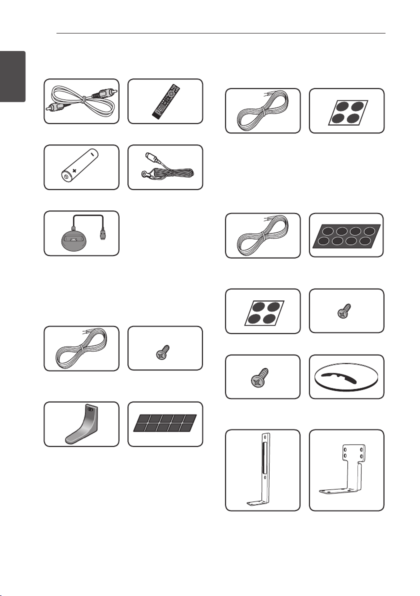
Remote control
1
Getting Started
1
2
3
Battery Installation
Remove the battery cover on
the rear of the Remote Control,
and insert an R03 (size AAA)
battery with 4 and 5 matched
correctly.
• • • • • • • • • a • • • • • • •
INPUT/TUNER: Changes
P
input mode.
(STANDBY/ON): Switches the
1
player ON or OFF.
OPEN/CLOSE: Opens and
B
closes the disc tray.
HDMI IN: Changes input mode
to HDMI IN directly.
OPTICAL: Changes input mode
to optical directly.
DISPLAY: Displays or exits
m
On-Screen Display.
HOME MENU: Displays or
n
exits the [Home Menu].
MENU: Accesses the menu on a
disc.
Direction buttons: Selects an
option in the menu.
ENTER: Acknowledges menu
b
selection.
TUNE (+/-): Tunes in the desired
radio station.
PRESET (
programme of Radio.
• • • • • • • • • b • • • • • • •
RETURN: Exits the menu or
x
resumes playback. The resume
play function may not work
depending on the BD-ROM disc.
POPUP/ TOP MENU: Displays
the DVD title menu or BD-ROM’s
pop-up menu, if available.
STOP: Stops playback.
Z
PLAY: Starts playback.
z
PAUSE/STEP: Pauses playback.
M
C/V
next or previous chapter / track /
le.
c/v
backward or forward.
SPK LEVEL: Sets the sound level
of desired speaker.
): Selects
W/S
SKIP: Goes to the
SCAN: Searches
USB REC: Records an audio
X
CD.
MUTE: Mute the unit.
SOUND: Selects a sound eect
mode.
VOL +/- : Adjusts speaker
volume.
• • • • • • • • • c • • • • • • •
0-9 numerical buttons: Selects
numbered options in a menu
or inputs letters in the keypad
menu.
MARKER: Marks any point
during playback.
SEARCH: Displays or exits the
search menu.
REPEAT: Repeats a desired
h
section or sequence.
DIMMER: Dims the light on the
unit.
ZOOM: Accesses the zoom
menu.
CLEAR: Removes a mark on the
search menu or a number when
setting the password.
Coloured (A, B, C, D) buttons:
Use to navigate on menus.
- A button (RDS): Radio Data
System.
- B button (PTY): Views the
programme type of the RDS.
- C button (PTY SEARCH):
Searches programme type.
- D button: Selects MONO or
STEREO in FM mode.
TV Control Buttons: See page
64.
SLEEP: Sets a certain period of
time after which the unit will
switch to o.
Page 15
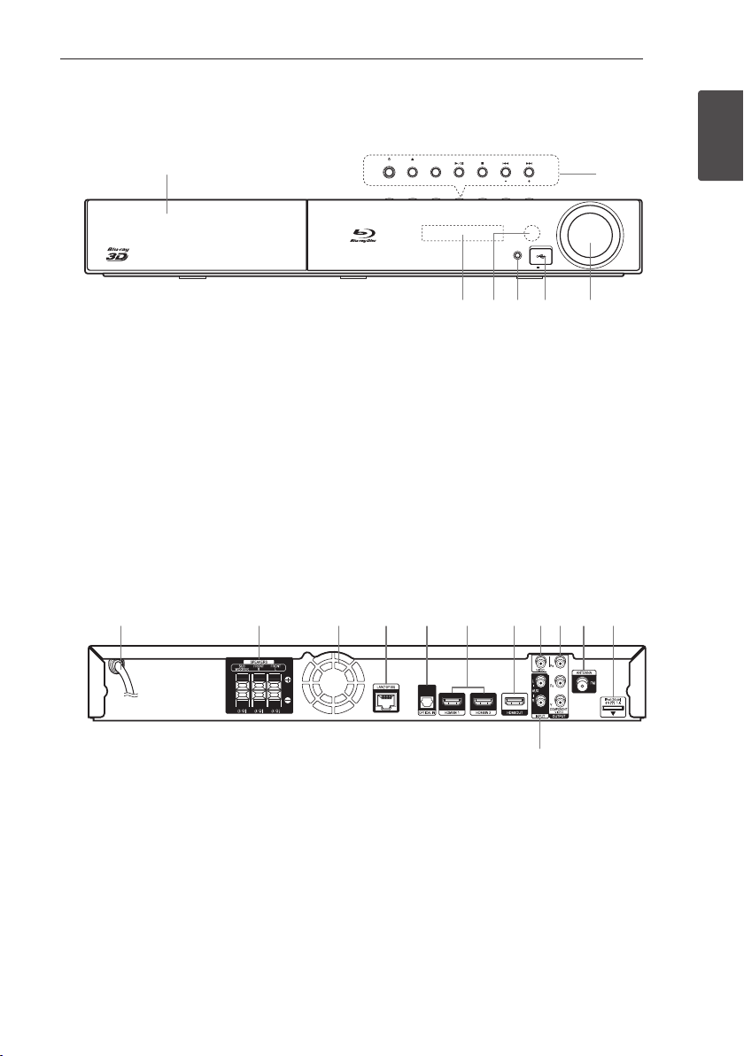
Front panel
a
STANDBY/ON OPEN/CLOSE FUNCTION
TUNE
VOLUME
PORTABLE IN
5 V 500 mA
a
b
dc e f g
Getting Started 15
STANDBY/ON OPEN/CLOSE FUNCTION
dc e f g
Disc Tray
a
Operation buttons
b
(STANDBY/ON) Button
1
Switches the player ON or OFF.
(OPEN/CLOSE)
B
FUNCTION
Display Window
c
Remote Sensor
d
PORTABLE IN
e
USB Port
f
Volume Control
g
Changes the input source or function.
(PLAY / PAUSE)
d/M
(STOP)
Z
C/V
(SKIP)
- TUNE + (Radio tuning)
Rear panel
a b c d e f g h i j k
PORTABLE IN
TUNE
5 V 500 mA
b
VOLUME
1
Getting Started
AC power cord
a
Speakers connectors
b
Cooling Fan
c
LAN port
d
OPTICAL IN
e
HDMI IN 1/2
f
HDMI OUT
g
VIDEO OUT
h
COMPONENT VIDEO (Y P
i
l
OUTPUT (PROGRESSIVE SCAN)
Antenna Connector
j
iPod (24 pin)
k
Connect to the furnished iPod cradle.
AUX (L/R) INPUT
l
b Pr)
Page 16
Connecting16
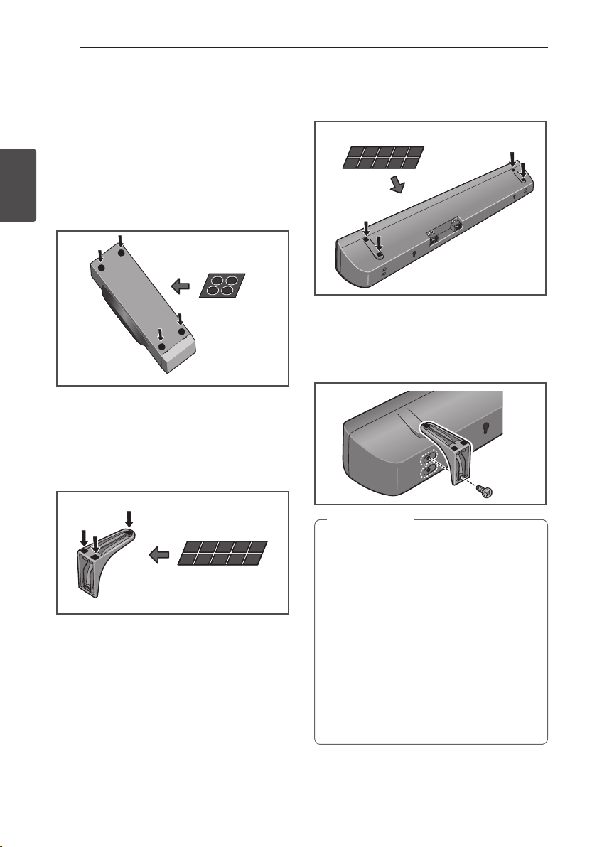
Assemble the speakers
Speaker Setup for BCS-SB616
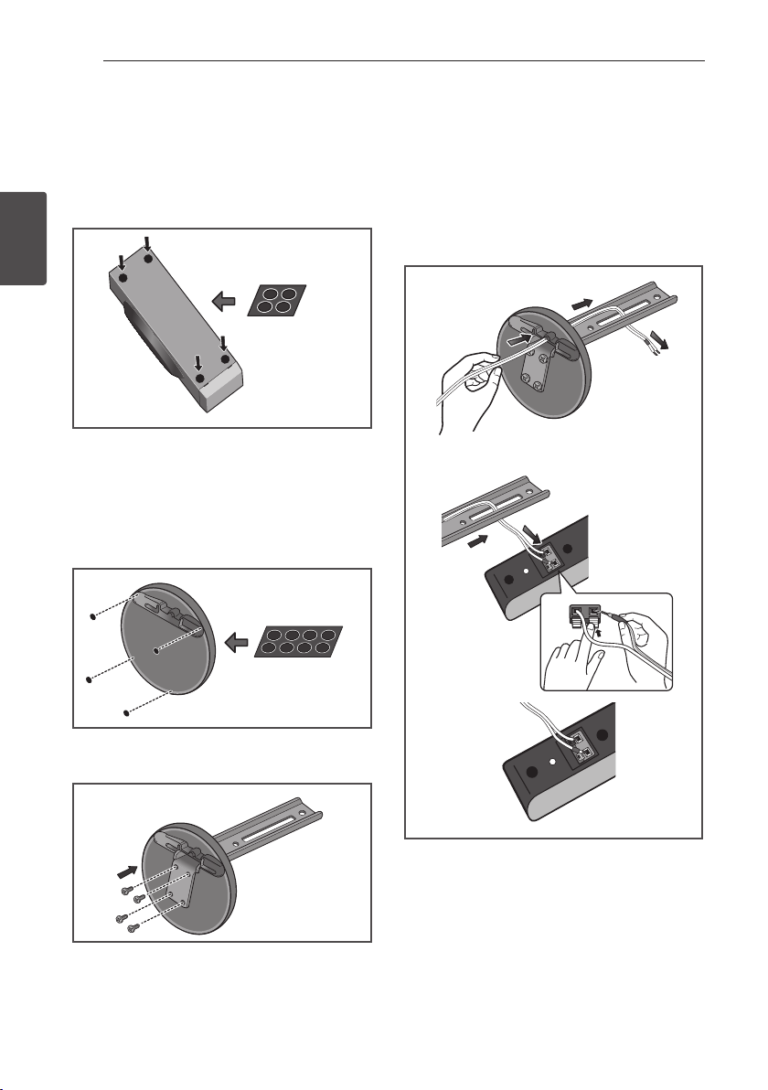
Preparing the speakers
For subwoofer:
Use the supplied adhesive to attach four large pads
2
to the base of subwoofer.
Connecting
Large non-skid pads
For front speaker:
Assembling the speaker stands and securing your
front speaker.
1. Use the supplied adhesive to attach three small
pads to the base (bottom) of each speaker
stand.
If you decide not to use the speaker stands, use the
supplied adhesive to attach four small pads to the
base of the speaker.
Small non-skid pads
2. Attach the speaker stand bases to the speaker.
Attach both right and left speaker stands to the
rear of the speaker. The height of the speaker
stands can be adjusted in two levels; select the
height you prefer, and x in position.
Small non-skid pads
Caution
>
yBe careful not to tighten screws excessively.
yIf excessive force is used to tighten screws,
the threads of screw may be damaged. Use
a middle-sized manual screwdriver during
assembly.
yDo not use power screwdrivers or oversized
screwdrivers that may exert excessive force
on the screws.
yConrm that no foreign matter is stuck to
the stand or the speaker during assembly.
yIf the unit is assembled with foreign matter
stuck between the stand and the speaker
the unit may not be assembled securely,
resulting in tipping or falling.
Page 17
Connecting 17
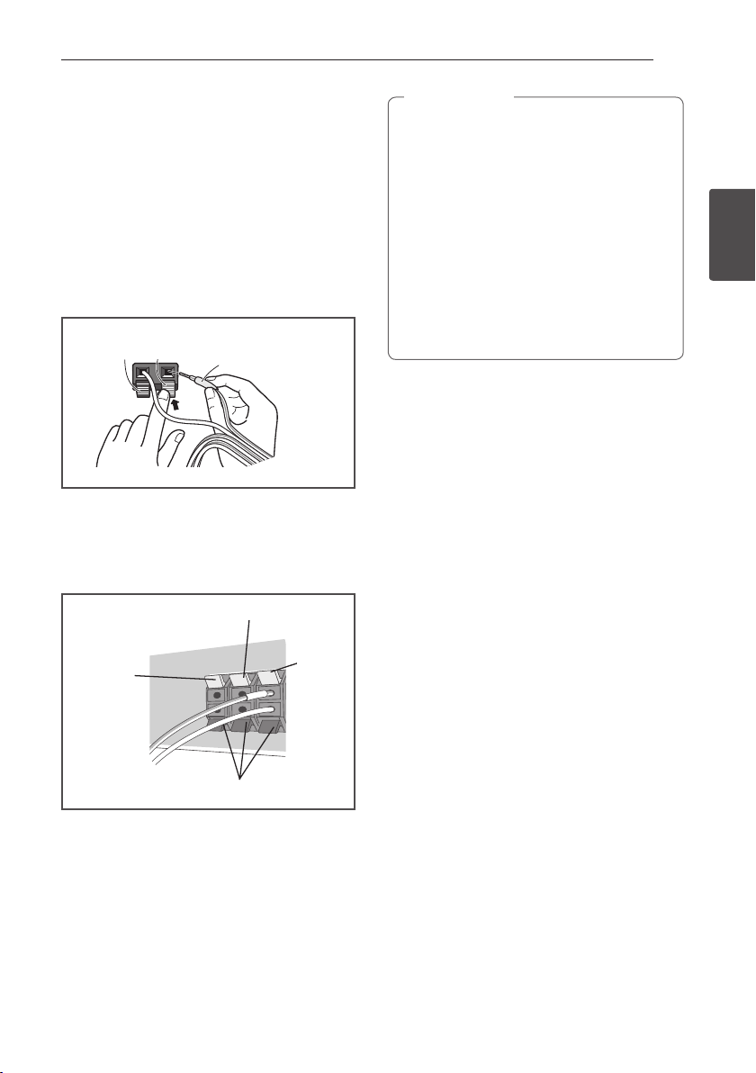
3. Connect each speaker.
Connect the wires to the speaker.
The rear of the speaker has channel terminals
(Right/Left), together with color-coded labels.
-Front left: White
-Front right: Red
-Subwoofer: Purple
Match the color-coded wire with the color
indicator on the label, then insert the
colorcoded wire into the red (+) side and the
other wire into the black (–) side.
Red (+)
Black (–)
Colour-coded wire
Connect the white wire with gray line into (+)
side and the other wire into (–) side. To connect
the cable to the player, press each plastic nger
pad to open the connection terminal. Insert the
wire and release the nger pad.
Red (+)
Red (+)
Caution
>
yDo not connect any speakers other than
those supplied to this system.
yDo not connect the supplied speakers to
any amplier other than the one supplied
with this system. Connection to any other
amplier may result in malfunction or re.
yPlease connect the speaker cable of
subwoofer (purple) to orange of the player.
yThese speaker terminals carry HAZARDOUS
LIVE voltage. To prevent the risk of electric
shock when connecting or disconnecting
the speaker cables, disconnect the power
cord before touching any uninsulated parts.
2
Connecting
Orange (+)
Orange (+)
Black (–)
Black (-)
White (+)
White (+)
Page 18
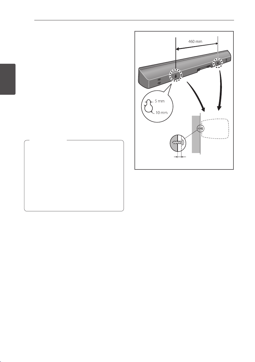
Connecting18
Wall mounting the speaker for
BCS-SB616
The speaker have the mounting holes which can
be used to mount the speaker on the wall.
Before mounting
yRemember that the speaker system is heavy and
that its weight could cause the screws to work
2
Connecting
loose, or the wall material to fail to support it,
resulting in the speaker falling. Make sure that
the wall you intend to mount the speaker on is
strong enough to support them. Do not mount
on plywood or soft surface walls.
yMounting screws are not supplied. Use screws
suitable for the wall material and support the
weight of the speaker.
Caution
>
yIf you are unsure of the qualities and
strength of the wall, consult a professional
for advice.
yPioneer is not responsible for any accidents
or damage that result from improper
installation.
yWhen mounting the speaker on a wall,
install it so that it is parallel to the oor.
yWhen mounting the speaker on a wall, do
not attach the accessory speaker stands.
Mounting screw
(not supplied)
4 mm to 5 mm
Page 19

Connecting 19
A
B
C
D
A
D
B
C
A
A B C D
A
D
B
A
A
D
B
A
D
B
A
Additional notes on speaker
placement for BCS-SB616
Install the speaker below the TV, in the center
position.
Precautions:
yDo not rest the speaker on the TV itself.
yMake sure that all the bare speaker wire is
twisted together and inserted fully into the
speaker terminal. If any of the bare speaker wire
touches the back panel it may cause the power
to cut o as a safety measure.
yThe front speaker and subwoofer are not
magnetically shielded and so should not be
placed near a TV or monitor. Magnetic storage
media (such as oppy discs and tape or video
cassettes) should also not be kept close to the
front speaker and subwoofer.
yDo not attach the subwoofer to a wall or ceiling.
They may fall o and cause injury.
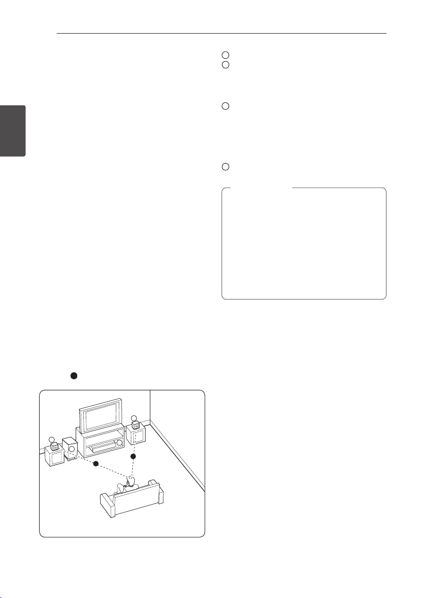
Positioning the system for
BCS-SB616
Front speaker
Subwoofer:
The position of the subwoofer is not so critical,
because low bass sounds are not highly directional.
But it is better to place the subwoofer near the
front speaker. Turn it slightly toward the center of
the room to reduce the wall reections.
Unit
Listening position
Caution
>
yBe careful to make sure children do not
put their hands or any objects into the
*subwoofer duct.
*subwoofer duct: A hole for plentiful bass
sound on subwoofer cabinet (enclosure).
yThe speakers contain magnet parts, so
colour irregularity may occur on the TV
screen or PC monitor screen. Please use the
speakers away from the TV screen or PC
monitor screen.
2
Connecting
Page 20
Connecting20
Speaker Setup for BCS-FS515
Preparing the speakers
For subwoofer:
Use the supplied adhesive to attach four large pads
to the base of subwoofer.
2
Connecting
For front speakers:
Assembling the speaker stands and securing your
front speakers.
For vertical instllation
1. Use the supplied adhesive to attach 4 small
pads to the speaker stand base.
Large non-skid pads
Small non-skid pads
3. Insert the speaker cord from the hole behind
the base through to the pole and connect it to
the speaker terminal. After connecting, put the
speaker wire in the gap on the back side of the
speaker.
Match the colour-corded wire with the colour
indicator on the label, then insert the colourcorded wire into the red (+) side and the other
wire into the black (–) side.
2. Insert the large pole from the holes behind the
base and secure with the 4 screws.
Page 21
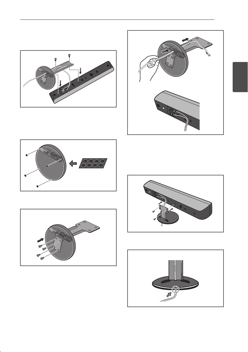
4. Secure the speaker and the pole with 2 screws.
Ensure that the speaker wire does not get
pinched between the speaker and the pole.
For horizontal installation
1. Use the supplied adhesive to attach 4 small
pads to the speaker stand base.
Small non-skid pads
Connecting 21
2
Connecting
4. Secure the speaker and the pole with 2 screws.
Ensure that the speaker wire does not get
pinched between the speaker and the pole. The
height of the speaker stands can be adjusted in
two levels; select the height you prefer, and x
in position.
2. Insert the small pole from the holes behind the
base and secure with the 4 screws.
3. Insert the speaker cord from the hole behind
the base through to the pole and connect it to
the speaker terminal. After connecting, put the
speaker wire in the gap on the back side of the
speaker.
Match the colour-corded wire with the colour
indicator on the label, then insert the colourcorded wire into the red (+) side and the other
wire into the black (–) side.
5. After connecting, put the speaker wire in the
back of the base of the stand.
Page 22
22
Connecting
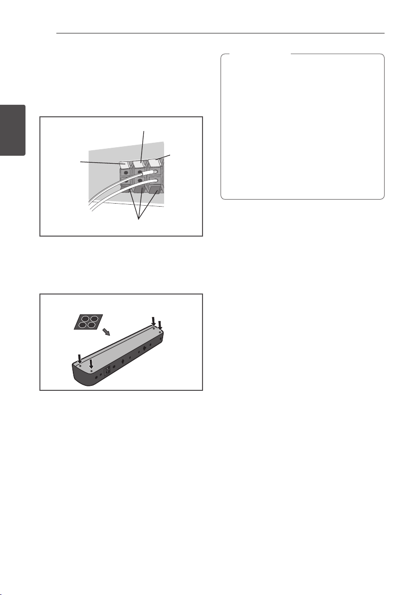
6. Connect the wires to the player.
Connect the white wire with gray line into (+)
side and the other wire into (–) side. To connect
the cable to the player, press each plastic nger
pad to open the connection terminal. Insert the
wire and release the nger pad.
Red (+)
Red (+)
2
Connecting
Orange (+)
Orange (+)
Black (–)
Black (-)
For direct installation
Use the supplied adhesive to attach 4 pads to the
base of the front speakers.
Small non-skid pads
White (+)
White (+)
Caution
>
yDo not connect any speakers other than
those supplied to this system.
yDo not connect the supplied speakers to
any amplier other than the one supplied
with this system. Connection to any other
amplier may result in malfunction or re.
yPlease connect the speaker cable of
subwoofer (purple) to orange of the player.
yThese speaker terminals carry HAZARDOUS
LIVE voltage. To prevent the risk of electric
shock when connecting or disconnecting
the speaker cables, disconnect the power
cord before touching any uninsulated parts.
Page 23
Connecting 23
Wall mounting the speakers
for BCS-FS515
Before mounting
yRemember that the speaker system is heavy and
that its weight could cause the screws to work
loose, or the wall material to fail to support it,
resulting in the speaker falling. Make sure that
the wall you intend to mount the speakers on is
strong enough to support them. Do not mount
on plywood or soft surface walls.
yMounting screws are not supplied. Use screws
suitable for the wall material and support the
weight of the speaker.
Caution
>
yIf you are unsure of the qualities and
strength of the wall, consult a professional
for advice.
yPioneer is not responsible for any accidents
or damage that result from improper
installation.
Mounting screw
(not supplied)
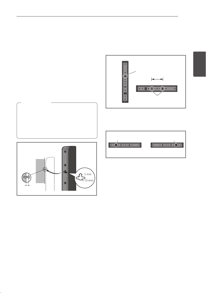
Attaching the speakers
The front speaker can be hung vertically or
horizontally on the wall. Use one hole to hang it
vertically and two holes to hang it horizontally. The
illustration below shows the front right speaker.
Vertical set up
Hole
110
Horizontal set up
Hole
When installing the speaker horizontally, set it up
so that the speaker terminal on the back side of the
speaker is on the outside on the end of the surface,
farthest away from the other speaker.
Speaker terminal Speaker terminal
Front right Front left
2
Connecting
5 mm to 7 mm
Page 24
Connecting24
A
A
A
A
BBCDEEF
G
A
A
D
B
C
A
A
D
B
C
A
A B C D
A
D
B
A
A
D
B
A
D
B
A
Additional notes on speaker
placement for BCS-FS515
Install the main front left and right speakers at an
equal distance from the TV.
Precautions:
yMake sure that all the bare speaker wire is
twisted together and inserted fully into the
2
Connecting
speaker terminal. If any of the bare speaker wire
touches the back panel it may cause the power
to cut o as a safety measure.
yThe front speakers and subwoofer is not
magnetically shielded and so should not be
placed near a TV or monitor. Magnetic storage
media (such as oppy discs and tape or video
cassettes) should also not be kept close to the
front speakers and subwoofer.
yDo not attach the subwoofer to a wall or ceiling.
They may fall o and cause injury.
Positioning the system for
BCS-FS515
The following illustration shows an example of
positioning the system. Note that the illustrations
in these instructions dier from the actual unit for
explanation purposes.
For the best possible surround sound, all the
speakers other than the subwoofer should be
placed at the same distance from the listening
position (
).
Front left speaker (L)/
Front right speaker (R):
Place the front speakers to the sides of the monitor
or screen and as ush with the screen surface as
possible.
Subwoofer:
The position of the subwoofer is not so critical,
because low bass sounds are not highly directional.
But it is better to place the subwoofer near the
front speakers. Turn it slightly toward the center of
the room to reduce the wall reections.
Unit
Caution
>
yBe careful to make sure children do not
put their hands or any objects into the
*subwoofer duct.
*subwoofer duct: A hole for plentiful bass
sound on subwoofer cabinet (enclosure).
yThe speakers contain magnetic parts, so
colour irregularity may occur on the TV
screen or PC monitor screen. Please use the
speakers away from the TV screen or PC
monitor screen.
Page 25
Connecting 25
Connecting to Your TV
Make one of the following connections, depending
on the capabilities of your existing equipment.
yHDMI connection (page 25)
yComponent Video connection (page 27)
yVideo connection (page 27)
Note
,
yDepending on your TV and other
equipment you wish to connect, there are
various ways you could connect the player.
Use only one of the connections described
in this manual.
yPlease refer to the manuals of your TV,
stereo system or other devices as necessary
to make the best connections.
yMake sure the player is connected directly
to the TV. Tune the TV to the correct video
input channel.
yDo not connect your player via your VCR.
The image could be distorted by the copy
protection system.
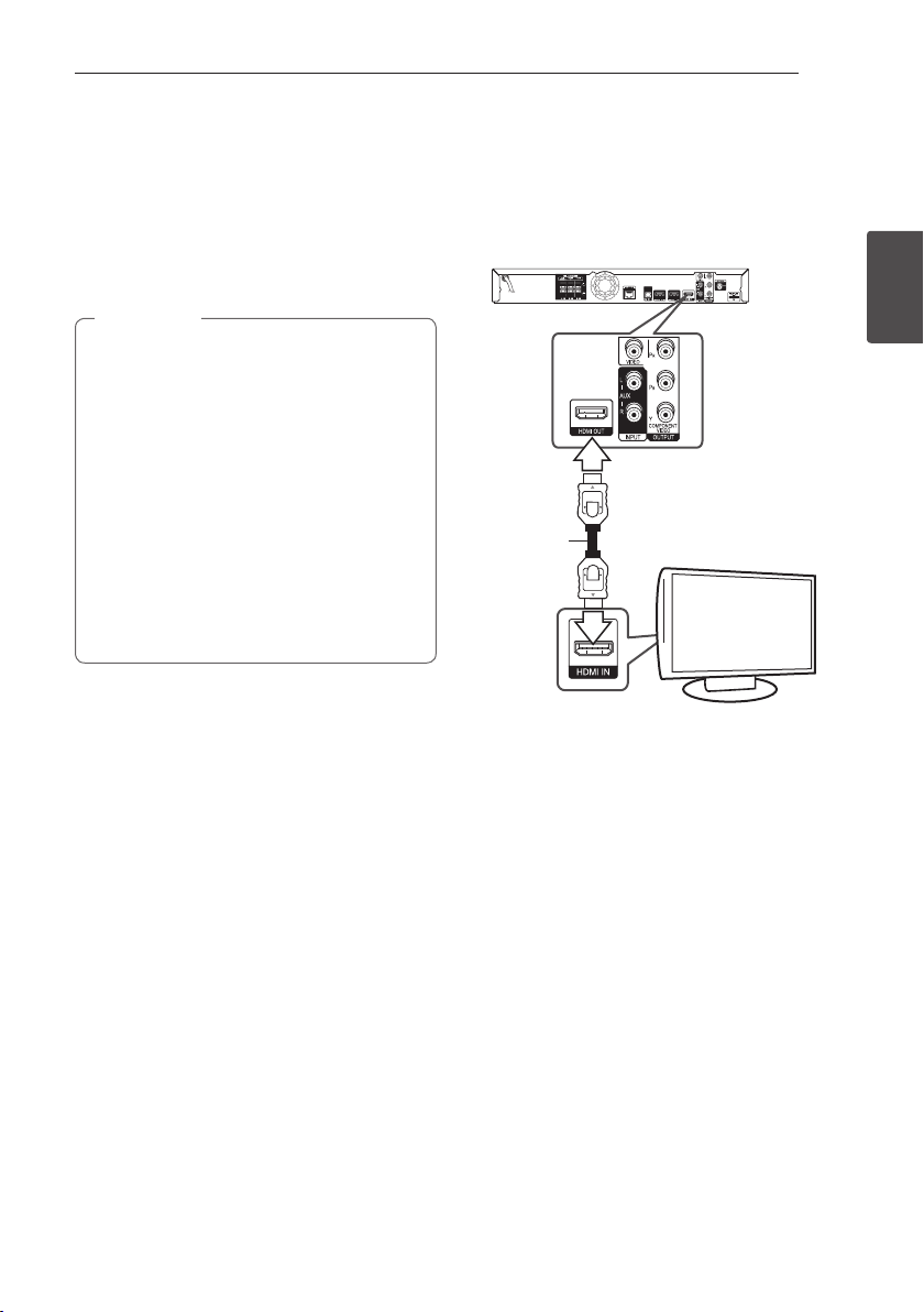
HDMI Connection
If you have a HDMI TV or monitor, you can connect
it to this player using a HDMI cable (Type A, High
Speed HDMI™ Cable with Ethernet). Connect the
HDMI jack on the player to the HDMI jack on a
HDMI compatible TV or monitor.
Rear of the unit
HDMI
cable
Set the TV’s source to HDMI (refer to TV’s Owner’s
manual).
TV
2
Connecting
Additional Information for HDMI
yWhen you connect a HDMI or DVI compatible
device make sure of the following:
-Try switching o the HDMI/DVI device and
this player. Next, switch on the HDMI/DVI
device and leave it for around 30 seconds,
then switch on this player.
-The connected device’s video input is set
correctly for this unit.
-The connected device is compatible with
720x576p, 1280x720p, 1920x1080i or
1920x1080p video input.
yNot all HDCP-compatible HDMI or DVI devices
will work with this player.
-The picture will not be displayed properly
with non-HDCP device.
Page 26

2
Connecting
Connecting26
Note
,
yIf a connected HDMI device does not accept
the audio output of the player, the HDMI
device’s audio sound may be distorted or
may not output.
yWhen you use HDMI connection, you can
change the resolution for the HDMI output.
(Refer to “Resolution Setting” on page 28.)
ySelect the type of video output from the
HDMI OUT jack using [HDMI Color Setting]
option on the [Setup] menu (see page 38).
yChanging the resolution when the
connection has already been established
may result in malfunctions. To solve the
problem, turn o the player and then turn it
on again.
yWhen the HDMI connection with HDCP
is not veried, TV screen is changed to
black screen. In this case, check the HDMI
connection, or disconnect the HDMI cable.
yIf there are noises or lines on the screen,
please check the HDMI cable (length is
generally limited to 4.5 m(15 ft.)).
ARC (Audio Return Channel)
function
The ARC function enables an HDMI capable TV to
send the audio stream to HDMI OUT of this player.
To use this function:
-Your TV must support the ARC function and
the ARC of this player must be set to On (Initial
setting is “O”).
-The setting method of ARC may dier depending
on the TV. For details about ARC function, refer
to your TV manual.
-You must use the HDMI cable (Type A, High
Speed HDMI™ Cable with Ethernet).
-You must connect with the HDMI IN of TV that
supports the ARC function using the HDMI OUT
on this player.
-You can connect only one Home Theater to TV
compatible with ARC.
-The ARC function does not warrant that the
function works in all cases even if the above
conditions are satised.
-When you use the ARC function, CEC (Consumer
Electronics Control) may work. If you do not want
to use CEC, you can stop it work by setting "ARC
O" on Home Menu. In this case, it is needed to
connect TV and this player by an optical cable to
send the audio stream to this player.
Page 27
Connecting 27
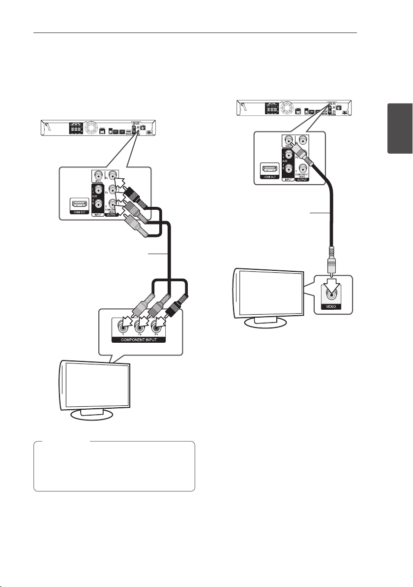
Component Video Connection
Connect the COMPONENT VIDEO OUT jacks on the
player to the corresponding input jacks on the TV
using component video cable. You can hear the
sound the through the system’s speaker.
Rear of the unit
Component
video cable
Video Connection
Connect the VIDEO OUT jack on the player to the
video in jack on the TV using a video cable. You can
hear the sound through the system’s speakers.
Rear of the unit
2
Connecting
Video cable
TV
TV
Note
,
When you use COMPONENT VIDEO OUT
connection, you can change the resolution for
the output. (Refer to “Resolution setting” on
page 28.)
Page 28
Connecting28
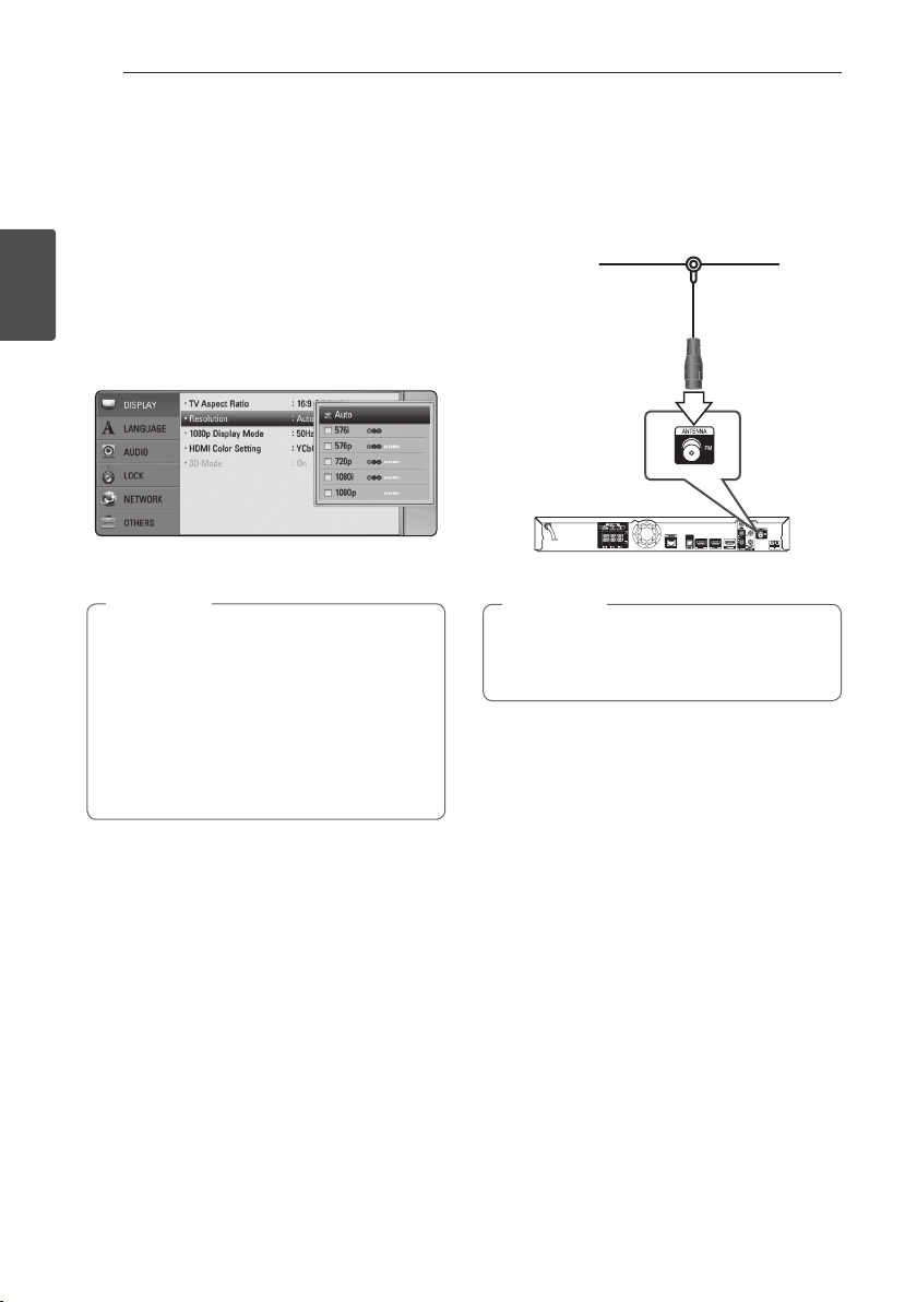
Resolution Setting
The player provides several output resolutions for
HDMI OUT and COMPONENT VIDEO OUTPUT jacks.
You can change the resolution using [Setup] menu.
1. Press HOME MENU (n).
2
Connecting
2. Use
(b). The [Setup] menu appears.
3. Use
press D to move to the second level.
4. Use
then press ENTER (b) to move to the third level.
5. Use
press ENTER (b) to conrm your selection.
yIf your TV does not accept the resolution
ySince several factors aect the resolution of
to select the [Setup] and press ENTER
A/D
to select [DISPLAY] option then
W/S
to select the [Resolution] option
W/S
to select the desired resolution then
W/S
Note
,
you have set on the player, you can set
resolution to 576p as follows:
1. Press B to open the disc tray.
2 Press Z (STOP) for more than 5 seconds.
video output, see “Video Output Resolution”
on page 69.
Antenna connection
Connect the supplied antenna for listening to the
radio.
Rear of the unit
Note
,
After connecting the FM wire antenna, keep
it as horizontal as possible. Be sure to fully
extend the FM wire antenna.
Page 29
Connecting 29
Connections with
external device
AUX Connection
You can enjoy the sound from an external
component through the speakers of this system.
Connect the analog audio output jacks of your
component into the AUX L/R (INPUT) on this unit.
And then select the [AUX] option by pressing
INPUT/TUNER and ENTER (b).
You can also use the FUNCTION button on the front
panel to select the input mode.
Rear of the unit
White
Red
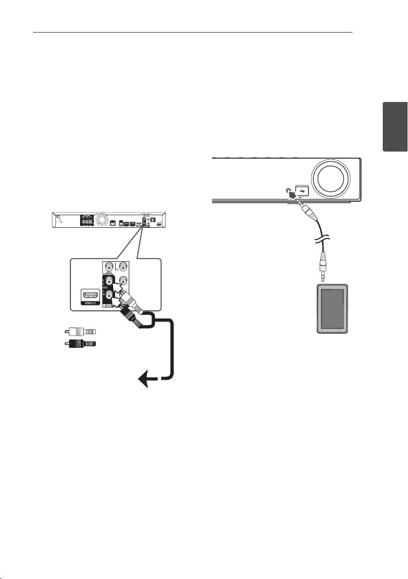
PORTABLE IN connection
You can enjoy the sound from your portable audio
player through the speakers of this system.
Connect the headphones (or line out ) jack of the
portable audio player into the PORTABLE IN socket
of this unit. And then select the [PORTABLE] option
by pressing INPUT/TUNER and ENTER (b).
You can also use the FUNCTION button on the front
panel to select the input mode.
VOLUME
PORTABLE IN
5 V 500 mA
MP3 Player, etc...
2
Connecting
To the audio output jacks
of your component
(TV, VCR, etc.)
Page 30
Connecting30
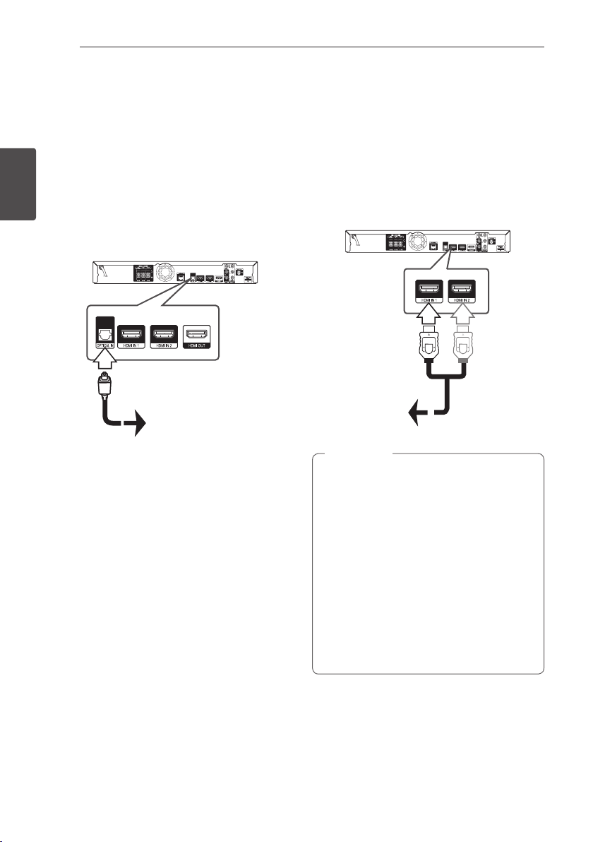
OPTICAL IN connection
You can enjoy the sound from your component
with a digital optical connection through the
speakers of this system.
Connect the optical output jack of your component
into the OPTICAL IN jack on the unit. And then
select the [OPTICAL] option by pressing INPUT/
TUNER and ENTER (b). Or press OPTICAL to select
directly.
2
You can also use the FUNCTION button on the front
Connecting
panel to select the input mode.
Rear of the unit
To the digital
optical output jack
of your component
HDMI IN 1/2 connection
You can enjoy the pictures and sound from your
component through this connection.
Connect the HDMI OUT jack of your component
into the HDMI IN 1 or 2 jack on this unit. And then
select the [HDMI IN 1/2] option by pressing INPUT/
TUNER and ENTER (b).
You can also use the FUNCTION button on the front
panel to select the input mode.
Rear of the unit
To the HDMI
OUT jack of your
component
(set-top box, digital
satellite receiver,
video game
machine, etc.)
Note
,
yYou cannot change the video resolution in
the HDMI IN 1/2 mode. Change the video
resolution of the connected component.
yIf the video output signal is abnormal when
your personal computer is connected to
HDMI IN 1/2 jack, change the resolution
of your personal computer to 576p, 720p,
1080i or 1080p.
yThe video signal from the HDMI input
cannot be output from the component or
composite video outputs.
yThe player sends audio from the HDMI
inputs to both the HDMI output and to the
unit’s speakers.
Page 31

Connecting to your
Connecting 31
Home Network
This player can be connected to a local area
network (LAN) via the LAN port on the rear panel or
the internal wireless module.
By connecting the unit to a broadband home
network, you have access to services such as BDLIVE interactivity and Online content services.
Wired network connection
Using a wired network provides the best
performance, because the attached devices
connect directly to the network and are not subject
to radio frequency interference.
Please refer to the documentation for your network
device for further instructions.
Connect the player’s LAN port to the corresponding
port on your Modem or Router using a
commercially available LAN or Ethernet cable.
Note
,
yWhen plugging or unplugging the LAN
cable, hold the plug portion of the cable.
When unplugging, do not pull on the LAN
cable but unplug while pressing down on
the lock.
yDo not connect a modular phone cable to
the LAN port.
ySince there are various connection
congurations, please follow the
specications of your telecommunication
carrier or internet service provider.
yIf you want to access content from PCs
or DLNA servers, this player must be
connected to the same local area network
with them via a router.
Broadband
service
2
Connecting
Router
PC and/or DLNA certied server
Rear of the unit
Page 32

Connecting32
Wired Network Setup
If there is a DHCP server on the local area network
(LAN) via wired connection, this player will
automatically be allocated an IP address. After
making the physical connection, a small number of
home networks may require the player’s network
setting to be adjusted. Adjust the [NETWORK]
setting as follow.
Preparation
2
Connecting
Before setting the wired network, you need to
connect the broadband internet to your home
network.
1. Select [Connection Setting] option in the
[Setup] menu then press ENTER (b).
2. The [Connection Setting] menu appear on the
screen. Use
press ENTER (b).
to select the [Wired] and
W/S
Note
,
If there is no DHCP server on the network and
you want to set the IP address manually, select
[Static] then set [IP Address], [Subnet Mask],
[Gateway] and [DNS Server] using
and numerical buttons. If you make a
A/D
mistake while entering a number, press CLEAR
to clear the highlighted part.
4. Select [OK] and press ENTER (b) to apply
network settings.
5. The player will ask you to test the network
connection. Select [OK] and press ENTER (b) to
complete the network connection.
6. If you select [Test] and press ENTER (b) at
step 5 above, the network connection status is
displayed on the screen.
You can also test it on the [Connection Status]
in the [Setup] menu.
W/S/
3. Use
W/S/A/D
between [Dynamic] and [Static].
Normally, select [Dynamic] to allocate an IP
address automatically.
to select the IP mode
Page 33

Wireless Network Connection
Another connection option is to use an Access Point
or a wireless router. The network conguration and
connection method may vary depending on the
equipment in use and the network environment.
This player is equipped with an IEEE 802.11n (Dualband, 5 GHz and 2.4 GHz band) wireless module,
which also supports the 802.11a/b/g standards.
For the best wireless performance, we recommend
using a IEEE 802.11n certied Wi-Fi network (access
point or wireless router).
VOLUME
PORTABLE IN
5 V 500 mA
Wireless
Communication
PC and/or
DLNA certied server
Access Point or
Wireless Router
Connecting 33
Note
,
Available frequency range and channels for
5 GHz band are listed as below. But, there
may have the dierences and restrictions
depending on the country. Try setting your
access point with other channel if you have
diculties in wireless network connection.
Area Frequency Range
North
America
Europe, UAE 5.15-5.25 GHz (ch. 36-48)
Others 5.15-5.25 GHz (ch. 36-48),
5.15-5.25 GHz (ch. 36-48),
5.725-5.825 GHz (ch. 149-161),
5.825- 5.850 (ch.165)
5.725-5.825 GHz (ch. 149-161),
5.825- 5.850 (ch.165)
Wireless Network Setup
For the wireless network connection, the player
needs to be set up for network communication.
This adjustment can be done from the [Setup]
menu. Adjust the [NETWORK] setting as follow.
Setting up the access point or the wireless router
is required before connecting the player to the
network.
2
Connecting
Broadband
service
Refer to the setup instructions supplied with
your access point or wireless router for detailed
connection steps and network settings.
For best performance, a direct wired connection
from this player to your home network’s router or
cable/DSL modem is always the best option.
If you do chose to use the wireless option, note that
performance can sometimes be aected by other
electronic devices in the home.
Preparation
Before setting the wireless network, you need to:
-connect the broadband internet to the wireless
home network.
-set the access point or wireless router.
-note the SSID and security code of the network.
1. Select [Connection Setting] option in the
[Setup] menu then press ENTER (b).
Page 34

Connecting34
2. The [Connection Setting] menu appear on the
screen. Use
ENTER (b).
3. Select [Yes] and press ENTER (b) to continue.
The new connection settings reset the current
network settings.
4. The player scans the all available access points
or wireless routers within range and display
them as a list. Use
2
Connecting
point or wireless router on the list, and then
press ENTER (b).
If you have security on your access point or
wireless router, verify that the WEP or WPA key
that was entered into the player matches the
router’s information exactly. You need to input
the security code as necessary.
Note
,
yWEP security mode generally have 4 keys
available on an access point or wireless
router’s setting. If your access point or
wireless router use WEP security, enter the
security code of the key “No.1” to connect
on your home network.
yAn Access Point is a device that allows you
to connect to your home network wirelessly.
yIf your access point or wireless router
supports the PIN Code conguration
method based on WPS(Wi-Fi Protected
Setup), press yellow (C) coloured button and
note the code number on the screen. And
then, enter the PIN number on a setting
menu of your access point or wireless router
to connect. Refer to the documentation for
your network device.
to select [Wireless] and press
W/S
to select an access
W/S
[Manual] – Your access point may not be
broadcasting its access point name (SSID).
Check your router settings through your
computer and either set your router to
broadcast SSID, or manually enter the access
point name (SSID) in [Manual].
[Push Button] – If your access point or
wireless router that supports the Push Button
Conguration method, select this option and
press the Push Button on your access point or
wireless router within 120 counts. You do not
need to know the access point name (SSID) and
security code of your access point or wireless
router.
5. Use
W/S/A/D
between [Dynamic] and [Static].
Normally, select [Dynamic] to allocate an IP
address automatically.
Note
,
If there is no DHCP server on the network and
you want to set the IP address manually, select
[Static] then set [IP Address], [Subnet Mask],
[Gateway] and [DNS Server] using
and numerical buttons. If you make a
A/D
mistake while entering a number, press CLEAR
to clear the highlighted part.
6. Select [OK] and press ENTER (b) to apply
network settings.
7. The player will ask you to test the network
connection. Select [OK] and press ENTER (b) to
complete the network connection.
8. If you select [Test] and press ENTER (b) at
step 7 above, the network connection status is
displayed on the screen. You can also test it on
the [Connection Status] in the [Setup] menu.
to select the IP mode
W/S/
Page 35

Connecting 35
Notes on Network Connection:
yMany network connection problems during
set up can often be xed by re-setting the
router or modem. After connecting the player
to the home network, quickly power o and/
or disconnect the power cable of the home
network router or cable modem. Then power on
and/or connect the power cable again.
yDepending on the internet service provider (ISP),
the number of devices that can receive internet
service may be limited by the applicable terms
of service. For details, contact your ISP.
yOur company is not responsible for any
malfunction of the player and/or the internet
connection feature due to communication
errors/malfunctions associated with your
broadband internet connection, or other
connected equipment.
yThe features of BD-ROM discs made available
through the Internet Connection feature are not
created or provided by our company, and our
company is not responsible for their functionality
or continued availability. Some disc related
material available by the Internet Connection
may not be compatible with this player. If you
have questions about such content, please
contact the producer of the disc.
ySome internet contents may require a higher
bandwidth connection.
yEven if the player is properly connected and
congured, some internet contents may not
operate properly because of internet congestion,
the quality or bandwidth of your internet service,
or problems at the provider of the content.
ySome internet connection operations may not
be possible due to certain restrictions set by the
Internet service provider (ISP) supplying your
broadband Internet connection.
yAny fees charged by an ISP including, without
limitation, connection charges are your
responsibility.
yA 10 Base-T or 100 Base-TX LAN port is required
for wired connection to this player. If your
internet service does not allow for such a
connection, you will not be able to connect the
player.
yYou must use a Router to use xDSL service.
yA DSL modem is required to use DSL service and
a cable modem is required to use cable modem
service. Depending on the access method of and
subscriber agreement with your ISP, you may not
be able to use the internet connection feature
contained in this player or you may be limited
to the number of devices you can connect at
the same time. (If your ISP limits subscription to
one device, this player may not be allowed to
connect when a PC is already connected.)
yThe use of a “Router” may not be allowed or its
usage may be limited depending on the policies
and restrictions of your ISP. For details, contact
your ISP directly.
yThe wireless network operate at 2.4 GHz
radio frequencies that are also used by other
household devices such as cordless telephone,
Bluetooth® devices, microwave oven, and can be
aected by interference from them.
yTurn o all unused network equipment in
your local home network. Some devices may
generate network trac.
yFor the purpose of the better transmission,
placing the player from the access point as close
as possible.
yIn some instances, placing the access point or
wireless router at least 0.45 m (1.5 ft.) above the
oor may improve the reception.
yMove closer to the access point if possible or re-
orient the player so there is nothing between it
and the access point.
yThe reception quality over wireless depends on
many factors such as type of the access point,
distance between the player and access point,
and the location of the player.
ySet your access point or wireless router to
Infrastructure mode. Ad-hoc mode is not
supported.
2
Connecting
Page 36

Connecting36
USB device connection
This player can play movie, music and photo les
contained in the USB device.
Playback content in the USB
device
1. Insert a USB device to the USB port until it ts
2
Connecting
into place.
PORTABLE IN
5 V 500 mA
2. Press HOME MENU (n).
3. Select [Movie], [Photo] or [Music] using
and press ENTER (b).
4. Select the [USB] option using
ENTER (b).
5. Select a le using
PLAY or ENTER (b) to play the le.
6. Withdraw the USB device carefully.
W/S/A/D
W/S
, and press
VOLUME
A/D
, and press
Note
,
yThis player supports USB ash drive/
external HDD formatted in FAT16, FAT32 and
NTFS when accessing les (music, photo,
movie). However, for BD-LIVE and Audio CD
recording, only FAT16 and FAT32 formats
are supported. Use the USB ash drive/
external HDD formatted in either FAT16 or
FAT32 when using BD-LIVE and Audio CD
recording.
yThe USB device can be used for the local
storage for enjoying BD-LIVE discs with
Internet.
yThis unit can support up to 8 partitions of
the USB device.
yDo not extract the USB device during
operation (play, etc.).
yA USB device which requires additional
program installation when you have
connected it to a computer, is not
supported.
,
yUSB device: USB device that supports
USB1.1 and USB2.0.
yMovie, music and photo les can be played.
For details of operations on each le, refer
to relevant pages.
yRegular back up is recommended to
prevent data loss.
yIf you use a USB extension cable, USB HUB
or USB Multi-reader, the USB device may not
be recognized.
ySome USB device may not work with this
unit.
yDigital camera and mobile phone are not
supported.
yUSB Port of the unit cannot be connected
to PC. The unit cannot be used as a storage
device.
Page 37

System Setting 37
Settings
Adjust the Setup Settings
You can change the settings of the player in the
[Setup] menu.
1. Press HOME MENU (n).
2. Use
(b). The [Setup] menu appears.
3. Use
press D to move to the second level.
to select the [Setup] and press ENTER
A/D
to select the rst setup option, and
W/S
[DISPLAY] Menu
TV Aspect Ratio
Select a TV aspect ratio option according to your TV
type.
[4:3 Letter Box]
Select when a standard 4:3 TV is connected.
Displays theatrical images with masking bars
above and below the picture.
[4:3 Pan Scan]
Select when a standard 4:3 TV is connected.
Displays pictures cropped to ll your TV screen.
Both sides of the picture are cut o.
[16:9 Original]
Select when a 16:9 wide TV is connected. The
4:3 picture is displayed with an original 4:3
aspect ratio, with black bars appearing at the
left and right sides.
[16:9 Full]
Select when a 16:9 wide TV is connected. The
4:3 picture is adjusted horizontally (in a linear
proportion) to ll the entire screen.
Note
,
You cannot select [4:3 Letter Box] and
[4:3 Pan Scan] option when the resolution is
set to higher than 720p.
3
System Setting
4. Use
press ENTER (b) to move to the third level.
5. Use
ENTER (b) to conrm your selection.
to select a second setup option, and
W/S
to select a desired setting, and press
W/S
Page 38

System Setting38
Resolution
Sets the output resolution of the Component and
HDMI video signal. Refer to page 28 and 69 for
details about the resolution setting.
[Auto]
If the HDMI OUT jack is connected to
TVs providing display information (EDID),
automatically selects the resolution best suited
to the connected TV.
[1080p]
Outputs 1080 lines of progressive video.
[1080i]
3
System Setting
Outputs 1080 lines of interlaced video.
[720p]
Outputs 720 lines of progressive video.
[576p]
Outputs 576 lines of progressive video.
[576i]
Outputs 576 lines of interlaced video.
1080p Display Mode
When the resolution is set to 1080p, select
[24 Hz] for smooth presentation of lm material
(1080p/24 Hz) with a HDMI-equipped display
compatible with 1080p/24 Hz input.
Note
,
yWhen you select [24 Hz], you may
experience some picture disturbance when
the video switches video and lm material.
In this case, select [50 Hz].
yEven when [1080p Display Mode] is set to
[24 Hz], if your TV is not compatible with
1080p/24 Hz, the actual frame frequency of
the video output will be 50 Hz to match the
video source format.
ySince several factors aect the resolution of
video output, see "Video Output Resolution"
on page 69.
HDMI Color Setting
Select the type of output from the HDMI OUT jack.
For this setting, please refer to the manuals of your
display device.
[YCbCr]
Select when connecting to a HDMI display
device.
[RGB]
Select when connecting to a DVI display
device.
3D Mode
Select the type of output mode for Blu-ray 3D disc
playback.
[O]
Blu-ray 3D disc playback will output as 2D
mode like a normal BD-ROM disc playback.
[On]
Blu-ray 3D disc playback will output as 3D
mode.
Page 39

System Setting 39
[LANGUAGE] Menu
Display Menu
Select a language for the [Setup] menu and onscreen display.
Disc Menu/Disc Audio/
Disc Subtitle
Select the language you prefer for the audio track
(disc audio), subtitles, and the disc menu.
[Original]
Refers to the original language in which the
disc was recorded.
[Other]
Press ENTER (b) to select another language.
Use number buttons then press ENTER (b)
to enter the corresponding 4-digit number
according to the language code list on page
66.
[O] (Disc Subtitle only)
Turn o Subtitle.
Note
,
Depending on the disc, your language setting
may not work.
[AUDIO] Menu
Speaker Setup
To obtain the best possible sound, use the speaker
setup display to specify the volume of the speakers
you have connected and their distance from your
listening position. Use the test to adjust the volume
of the speakers to the same level.
3
System Setting
[Speaker]
Select a speaker that you want to adjust.
[Volume]
Adjust the output level of each speaker.
[Distance]
Adjust the distance between each speaker and
the listening position.
[Test/ Stop test tone]
The speakers will emit a test tone.
[OK]
Conrms the setting.
[Cancel]
Cancels the setting.
Page 40

System Setting40
HD AV Sync
Sometimes Digital TV encounters a delay between
picture and sound. If this happens you can
compensate by setting a delay on the sound so
that it eectively ‘waits’ for the picture to arrive: this
is called HD AV Sync. Use
down through the delay amount, which you can
set at anything between 0 and 300 ms.
W/S
3
System Setting
DRC (Dynamic Range Control)
This function allows you to listen to a movie at a
lower volume without losing clarity of sound.
[O]
Turns o this function.
[On]
Compress the dynamic range of the Dolby
Digital, Dolby Digital Plus or Dolby TrueHD
audio output.
[Auto]
The dynamic range of the Dolby TrueHD audio
output is specied by itself.
And the dynamic range of the Dolby Digital
and Dolby Digital Plus are operated as same as
the [On] mode.
Note
,
The DRC setting can be changed only when a
disc is not inserted or the unit is in complete
stop mode.
to scroll up and
[LOCK] Menu
The [LOCK] settings aect only Blu-ray Disc and
DVD playback.
To access the any features in [LOCK] settings, you
must enter the 4-digit security code you have
created.
If you have not entered a password yet, you are
prompted to do so. Enter a 4-digit password twice,
and press ENTER (b) to create a new password.
Password
You can create or change the password.
[None]
Enter a 4-digit password twice, and press
ENTER (b) to create a new password.
[Change]
Enter the current password and press ENTER
(b). Enter a 4-digit password twice, and press
ENTER (b) to create a new password.
If you forget your password
If you forget your password, you can clear it using
the following steps:
1. Remove any disc that might be in the player.
2. Select [Password] option in the [Setup] menu.
3. Use Number buttons to enter “210499”. The
password is cleared.
Note
,
If you make a mistake before pressing ENTER
(b), press CLEAR. Then input the correct
password.
Page 41

System Setting
41
DVD Rating
Blocks playback of rated DVD based on their
content. (Not all discs are rated.)
[Rating 1-8]
Rating one (1) has the most restrictions and
rating eight (8) is the least restrictive.
[Unlock]
If you select [Unlock], parental control is not
active and the disc plays in full.
Blu-ray Disc Rating
Set an age limit of BD-ROM play. Use number
buttons to input an age limit for BD-ROM viewing.
[255]
All BD-ROM can be played.
[0-254]
Prohibits play of BD-ROM with corresponding
ratings recorded on them.
Note
,
The [Blu-ray Disc Rating] will be applied
only for the Blu-ray disc that containing the
Advanced Rating Control.
Area Code
Enter the code of the area whose standards were
used to rate the DVD video disc, based on the list
on page 65.
[NETWORK] Menu
The [NETWORK] settings are needed to use the BDLive and Online content services.
Connection Setting
If your home network environment is ready to
connect the player, the player needs to be set the
wired or wireless network connection for network
communication. (See “Connecting to your Home
Network” on pages 31-35.)
Connection Status
If you want to check the network status on this
player, select the [Connection Status] options and
press ENTER (b) to check whether a connection
to the network and the internet have been
established.
BD-LIVE connection
You can restrict Internet access when BD-LIVE
functions are used.
[Permitted]
Internet access is permitted for all BD-LIVE
contents.
[Partially permitted]
Internet access is permitted only for BDLIVE contents which have content owner
certicates. Internet access and AACS Online
functions are prohibited for all BD-LIVE
contents without a certicate.
[Prohibited]
Internet access is prohibited for all BD-LIVE
contents.
3
System Setting
Page 42

System Setting42
[OTHERS] Menu
ARC (Audio Return Channel)
You can set ARC (Audio Return Channel) function
[On] or [O]. The ARC function enables an HDMI
capable TV to send the audio stream to HDMI OUT
of this player. Refer to page 26 for details about this
function.
DivX® VOD
ABOUT DIVX VIDEO: DivX® is a digital video format
created by DivX, Inc. This is an ocial DivX Certied®
device that plays DivX video. Visit divx.com for more
information and software tools to convert your les
into DivX video.
3
System Setting
ABOUT DIVX VIDEO-ON-DEMAND: This DivX
Certied® device must be registered in order to play
purchased DivX Video-on-Demand (VOD) movies.
To obtain your registration code, locate the DivX
VOD section in your device setup menu. Go to vod.
divx.com for more information on how to complete
your registration.
[Register]
Displays the registration code of your player.
[Deregister]
Deactivate your player and display the
deactivation code.
Note
,
All the downloaded videos from DivX VOD
with this player’s registration code can only be
played back on this unit.
Initialize
[Factory Set]
You can reset the player to its original factory
settings.
[BD-LIVE Storage Clear]
Initializes the BD-LIVE contents from the
connected USB storage.
Note
,
If you reset the player to its original factory
settings using [Factory Set] option, you have
to set all the activation for the Online services
and network settings again.
Software Information
Displays the current software version.
Disclaimer Notice
Press ENTER (b) to view the notice of Network
Service Disclaimer.
Auto Power Off
The screen saver appears when you leave the
player in Stop mode for about ve minutes. If
you set this option to [On], the unit automatically
turns o within 25 minutes since the Screen Saver
is displayed. Set this option to [O] to leave the
screen saver until the unit is operated by the user.
Page 43

Sound Effect
You can select a suitable sound mode. Press SOUND
repeatedly until the desired mode appears on the
front panel display or the TV screen. The displayed
items for the equalizer maybe dierent depending
on sound sources and eects.
[Mode 1]: Gives you suitable sound setting with
connecting slim type of speakers (S-BD515FS).
[Mode 2]: Gives you suitable sound setting with
connecting bar type of speakers (S-BD616SB).
[Bypass]: Software with multichannel surround
audio signals is played according to the way it was
recorded.
[Bass Blast]: Reinforce the bass sound eect from
front left and right speaker and subwoofer.
[Clear Voice]: This mode makes voice sound clear,
improving the quality of voice sound.
[Game]: You can enjoy more virtual sound while
playing video games.
[Night]: This may be useful when you want to
watch movies at low volumes late at night.
[Mus. ReTouch]: When listening to MP3 les or
other compressed music, you can enhance the
sound. This mode is available only to 2 channel
sources. For Dolby Digital, Dolby Digital Plus and
Dolby True HD, it is available to 2 channel and
multichannel sources.
[Loudness]: Improves bass and treble sound.
System Setting 43
3
System Setting
Page 44

Operating44
General Playback
Using [HOME] menu
The home menu appears when you press HOME
MENU (n). Use
and press ENTER (b).
a
4
b
Operating
c
d
e
f
[Movie] - Plays video contents.
[Music] - Plays audio contents.
[Photo] - Plays photo contents.
[Online] - Displays the Online Home screen.
[Input] - Changes input mode.
[Setup] - Adjusts the system settings.
W/S/A/D
to select a category
Playing a Disc
ert
1. Press B (OPEN/CLOSE), and place a disc on the
disc tray.
2. Press B (OPEN/CLOSE) to close the disc tray.
For the most Audio CD, BD-ROM and
DVD-ROM discs, playback starts automatically.
3. Press HOME MENU (n).
4. Select [Movie] or [Music] using
ENTER (b).
5. Select [Blu-ray Disc], [DVD], [VR] or [Audio]
option using
Note
,
yPlayback functions described in this manual
are not always available in every les and
media. Some functions can be restricted
depending on many factors.
yDepending on the BD-ROM titles, a USB
device connection may be needed for the
proper playback.
yUnnalized DVD VR format discs may not be
played in this player.
ySome DVD-VR discs are made with CPRM
data by DVD RECORDER. This unit cannot
support these kinds of discs.
, and press ENTER (b).
W/S
A/D
, and press
Playing a file on a disc/USB
device
yui
This player can play movie, music and photo les
contained in the disc or USB device.
1. Insert a data disc on the tray or connect a USB
device.
2. Press HOME MENU (n).
3. Select [Movie], [Photo] or [Music] using
and press ENTER (b).
4. Select [Data] or [USB] option using
press ENTER (b).
5. Select a le using
(PLAY) or ENTER (b) to play the le.
d
W/S/A/D
A/D
W/S
, and press
, and
,
Page 45

Operating 45
Playing Blu-ray 3D disc
e
This player can play the Blu-ray 3D discs which
contains separate views for the left and right eyes.
Preparation
In order to playback Blu-ray 3D title in
stereoscopic 3D mode, you need to:
Check your TV is 3D capable and has HDMI
yyy
(3D) input(s).
y Wear 3D glasses to enjoy the 3D experience
if it is necessary.
Check whether the BD-ROM title is the Blu-
yyy
ray 3D disc or not.
Connect an HDMI cable (High Speed HDMI™
yyy
Cable with Ethernet) between the player’s
HDMI output and TV’s HDMI input.
1. Press HOME MENU (n), and set the [3D Mode]
option on the [Setup] menu to [On] (page 38).
2. Press B (OPEN/CLOSE), and place a disc on the
disc tray.
3. Press B (OPEN/CLOSE) to close the disc tray.
The playback starts automatically.
4. Refer to the owner’s manual of your 3D-ready
TV for the further instruction.
You may need to adjust the display settings and
focus on your TV’s setting for the improved 3D
eect.
Caution
>
yWatching a 3D content for a long period
time may cause dizziness or tiredness.
yIt is not recommended to watch a movie in
3D mode for inrm, child (particularly under
6) and pregnant woman.
yIf you are experiencing headache, tiredness
or dizziness while viewing contents in 3D,
it is strongly recommended to stop the
playback and rest until you feel normal.
Enjoying BD-Live™
e
BD-ROM supporting BD-Live (BD-ROM version 2
Prole 2) that has a network extension function
allows you to enjoy more functions such as
downloading new movie trailers by connecting this
unit to the internet.
1. Check the network connection and settings
(pages 31-35).
2. Insert a USB storage device to the USB port on
the front panel.
A USB storage device is needed to download
bonus content.
3. Press HOME MENU (n), and set the [BD-LIVE
connection] option on the [Setup] menu (page
41).
Depending on a disc, the BD-Live function may
not be operated if [BD-LIVE connection] option
is set to [Partially Permitted].
4. Insert a BD-ROM with BD-Live.
The operations are dier depending on the disc.
Refer to the manual supplied with the disc.
Caution
>
Do not extract the connected USB device
while content is being downloaded or a Bluray disc is still in the disc tray. Doing so may
damage the connected USB device and BDLive features may not operate properly with
the damaged USB device anymore. If the
connected USB device seems damaged from
such an action, you can format the connected
USB device from the PC and reuse it with this
player.
Note
,
ySome BD-Live contents may be restrictively
accessed in some territories by contents
provider’s own decision.
yIt may take up to several minutes to load
and start enjoying BD-Live contents.
4
Operating
Page 46

Operating46
Playing a file on a network
server
yui
This player can play movie, music and photo les
located in a PC or a DLNA server through your
home network.
1. Check the network connection and settings
(pages 31-35).
2. Press HOME MENU (n).
3. Select [Movie], [Photo] or [Music] using
and press ENTER (b).
4. Select a DLNA media server or a share folder
on your PC on the list using
ENTER (b).
4
Operating
If you want to rescan available media server,
press the green (B) coloured button.
5. Select a le using
ENTER (b) to play the le.
Note
,
yThe le requirements are described on page
11.
yThe thumbnail of the unplayable les can
be displayed, but those cannot be played
on this player.
yThe subtitle le name and movie le name
have to be the same and located at the
same folder.
yThe playback and operating quality may be
aected by your home network condition.
yYou may experience connection problems
depending on your server’s environment.
yDTCP-IP cannot be supported.
W/S/A/D
W/S
A/D
, and press
, and press
Entering a network user ID and the
password
Depending on your PC’s environment, you may
need to enter a network user ID and the password
for accessing a shared folder.
1. The keyboard menu appears automatically if the
network user ID and the password are required.
2. Use
W/S/A/D
press ENTER (b) to conrm your selection on
the virtual keyboard.
,
To enter a letter with an accent mark, press
DISPLAY (m) to display the extended character
set.
[Cancel] – Returns to the previous screen.
[Space] – Inserts a space at the cursor position.
[<–] – Deletes the previous character at the
cursor position.
[ABC / abc / #+-=&] – Change the keyboard
menu settings to capital letters, small letters or
symbols.
3. When you nish entering the network user ID
and password, select [OK] using
and press ENTER (b) to access the folder.
The network user ID and password will be
remembered after accessing the folder for your
convenience. If you do not want the network user
ID and password to be remembered, press red (A)
coloured button to un-tick the [Remember] check
box before accessing the folder.
to select a character then
W/S/A/D
Page 47

Operating 47
Basic operations for video and
audio content
To stop playback
Press Z (STOP) while playback.
To pause playback
Press M (PAUSE/STEP) while playback.
Press d (PLAY) to resume playback.
To play frame-by-frame (Video)
Press M (PAUSE/STEP) while movie playback.
Press M (PAUSE/STEP) repeatedly to play Frame-byFrame playback.
To scan forward or backward
Press c or v to play fast forward or fast reverse
during playback.
You can change the various playback speeds by
pressing c or v repeatedly.
To slow down the playing speed
While the playback is paused, press v repeatedly
to play various speeds of slow motion.
To skip to the next/previous
chapter/track/file
During playback, press C or V to go to the
next chapter/track/le or to return to the beginning
of the current chapter/track/le.
Press C twice briey to step back to the previous
chapter/track/le.
In the le list menu of a server, there may have
many types of contents in a folder together. In this
case, press C or V to go to the previous or
next content with same type.
Basic operations for photo
content
To play a slide show
Press d (PLAY) to start slide show.
To stop a slide show
Press Z (STOP) while slide show.
To pause a slide show
Press M (PAUSE/STEP) while slide show.
Press d (PLAY) to re-start the slide show.
To skip to the next/previous photo
While viewing a photo in full screen, press A or D
to go to the previous or next photo.
Using the disc menu
ero
To display the disc menu
The menu screen may be displayed rst after
loading a disc which contains a menu. If you want
to display the disc menu while playback, press
MENU.
Use
W/S/A/D
menu items.
To display the Pop-up menu
Some BD-ROM discs contain Pop-up menu that
appears while playback.
Press POPUP/TOP MENU while playback, and use
W/S/A/D
items.
buttons to navigate through
buttons to navigate through menu
4
Operating
Page 48

Operating48
Resume playback
eroyt
u
The unit records the point where you pressed the
(STOP) depending on the disc.
Z
If “MZ (Resume Stop)” appears on the screen briey,
press d (PLAY) to resume playback (from the scene
point).
If you press Z (STOP) twice or unload the disc,
“Z(Complete Stop)” appears on the screen. The unit
will clear the stopped point.
Note
,
yThe resume point may be cleared when a
button is pressed (for example;
(STANDBY/ON), B (OPEN/CLOSE), etc).
1
yOn BD-ROM discs with BD-J, the resume
playback function does not work.
4
Operating
yIf you press Z (STOP) once during BD-ROM
interactive title playback, the unit will be in
Complete Stop mode .
Page 49

Operating 49
Advanced Playback
Repeat Playback
erotu
During playback, press REPEAT (h) repeatedly to
select a desired repeat mode.
Blu-ray Disc/DVDs
A- – Selected portion will be repeated continually.
j
Chapter – The current chapter will be played
j
back repeatedly.
Title – The current title will be played back
j
repeatedly.
To return to normal playback, press REPEAT (h)
repeatedly to select [O].
Audio CDs/Music les
Track– The current track or le will be played
;
back repeatedly.
All – All the tracks or les will be played back
:
repeatedly.
– The tracks or les will be played back in
l
random order.
All – All the tracks or les will be played
l:
back repeatedly in random order.
A-B – Selected portion will be repeated
k
continually. (Audio CD only)
To return to normal playback, press CLEAR.
Note
,
yIf you press V once during Repeat
Chapter/Track playback, the repeat playback
cancels.
yThis function may not work on some disc or
title.
Repeating a specific portion
erot
This player can repeat a portion you have selected.
1. While playback, press REPEAT (h) to select
[A-] at the beginning of the portion you wish to
repeat.
2. Press ENTER (b) at the end of the portion. Your
selected portion will be repeated continually.
3. To return to normal playback, press REPEAT
(h) repeatedly to select [O].
Note
,
yYou cannot select a portion less than 3
seconds.
yThis function may not work on some disc or
title.
Enlarge the playback image
eroyi
1. During playback or pause mode, press ZOOM to
display the [Zoom] menu.
2. Use red (A) or green (B) coloured button to
zoom out or in the picture. You can move
through the zoomed picture using
buttons.
D
3. To return to the normal picture size, press yellow
(C) coloured button.
4. Press RETURN (x) to exit the [Zoom] menu.
W/S/A/
4
Operating
Page 50

50
Operating
Marker Search
eroy
You can start playback from up to nine memorized
points.
To enter a marker
1. While playback, press MARKER at the desired
point. The Marker icon appears on the TV screen
briey.
2. Repeat step 1 to add up to nine markers.
To recall a marked scene
1. Press SEARCH and the search menu appears on
the screen.
2. Press a number button to select a marker
number that you want to recall. Playback starts
from the marked scene.
To delete a Marker
4
Operating
1. Press SEARCH and the search menu appears on
the screen.
2. Press S to highlight a marker number.
Use
want to delete.
3. Press CLEAR and the marked scene is erased
from the search menu.
yThis function may not work depending on
yAll marked points are cleared if the title
yIf the total length of the title is less than 10
to select a marked scene that you
A/D
Note
,
discs, titles, server ability.
is in complete stop (Z) mode, the title is
changed or if you unload the disc.
seconds, this function is not available.
Using the search menu
eroy
Using search menu, you can easily to nd the point
where you want to start playback.
To search a point
1. During playback, press SEARCH to display the
search menu.
2. Press
forward or backward. You can select a point that
you want to skip by pressing and holding
A/D
To start playback from a marked
scene
1. Press SEARCH and the search menu appears on
the screen.
2. Press S to highlight a marker number. Use
A/D
to start playback.
3. Press ENTER (b) to start playback from the
marked scene.
yThis function may not work depending on
discs, titles, server ability.
yThis function may not work depending on
the le type and ability of the media server.
to skip the playback 15 seconds
A/D
button.
to select a marked scene that you want
Note
,
Page 51

Operating 51
Selecting a subtitle file
y
If the subtitle le name is dierent from the movie
le name, you need to select the subtitle le on the
[Movie] menu before playing the movie.
1. Use
W/S/A/D
wish to play in the [Movie] menu.
2. Press ENTER (b).
Press ENTER (b) again to deselect the subtitle
le. Selected subtitle le will be displayed when
you play the movie le.
Note
,
yIf you press Z (STOP) while playback, the
subtitle selection is cancelled.
yThis function is not available for playing le
on a server via home network.
to select the subtitle le you
Last Scene Memory
er
This unit memorizes the last scene from the last disc
that is viewed. The last scene remains in memory
even if you remove the disc from the unit or switch
o the unit. If you load a disc that has the scene
memorized, the scene is automatically recalled.
Note
,
yLast Scene Memory function for a previous
disc is erased once a dierent disc is played.
yThis function may not work depending on
the disc.
yOn BD-ROM discs with BD-J, the last scene
memory function does not work.
yThis unit does not memorize settings of
a disc if you switch o the unit before
commencing to play it.
4
Operating
Page 52

Operating52
Options while viewing a photo
i
You can use various options during viewing a
photo in full screen.
1. While viewing a photo in full screen, press
DISPLAY (m) to display the option menu.
2. Select an option using
4
Operating
a Current photo/Total number of photos
– Use
A/D
b Slide Show – Press ENTER (b) to start or
pause slide show.
c Music Select – Select the background
music for the slide show (page 52).
d Music –Press ENTER (b) to start or pause
background music.
e Rotate – Press ENTER (b) to rotate the
photo clockwise.
f Zoom – Press ENTER (b) to display the
[Zoom] menu.
g Eect – Use
eect between photos in a slide show.
h Speed – Use
speed between photos in a slide show.
3. Press RETURN (x) to exit the option menu.
W/S
to view previous/next photo.
to select a transition
A/D
to select a delaying
A/D
Listening to music while slide
show
i
You can display photo les while listening to music
les.
.
1. While viewing a photo in full screen, press
DISPLAY (m) to display the option menu.
2. Use
press ENTER (b) to display the [Music Select]
menu.
3. Use
(b).
Device that you can select are dier depending
on the location of the photo le you are
displaying in full screen.
4. Use
play.
Select g and press ENTER (b) to display the
upper directory.
When selecting music le from a server, folder
selection is not available. Only le selection is
available.
to select [Music Select] option, and
W/S
to select a device, and press ENTER
W/S
Photo location Available Device
Disc, USB Disc, USB
Share Folder (PC) Share Folder (PC)
DLNA server DLNA server
to select a le or a folder you wish to
W/S
Note
,
5. Use D to select [OK], and press ENTER (b) to
complete music selection.
Page 53

Operating 53
On-Screen display
You can display and adjust various information and
settings about the content.
Displaying content information
on-screen
eroy
1. While playback, press DISPLAY (m) to show
various playback information.
a Title – current title number/total number of
titles
b Chapter – current chapter number/total
number of chapters
c Time – elapsed playing time/total playback
time
d Audio – selected audio language or channel
e Subtitle – selected subtitle.
f Angle – selected angle/total number of
angles
g TV Aspect Ratio – selected TV aspect Ratio
h Picture Mode – selected picture mode
2. Select an option using
3. Use
4. Press RETURN (x) to exit the On-Screen
display.
yIf no button is pressed for a few seconds,
yA title number cannot be selected on some
yAvailable items may dier depending on
y If an interactive Blu-ray Disc is playing back,
to adjust the selected option value.
A/D
Note
,
the on-screen display disappears.
discs.
discs or titles.
some setting information is displayed on
the screen but prohibited to be changed.
W/S
.
4
Operating
Page 54

Operating54
Playing from selected time
eroy
1. Press DISPLAY (m) during playback. The time
search box shows the elapsed playing time.
2. Select the [Time] option and then input the
required start time in hours, minutes, and
seconds from left to right.
For example, to nd a scene at 2 hours, 10
minutes, and 20 seconds, enter “21020”.
Press
forward or backward.
3. Press ENTER (b) to start playback from selected
time.
yThis function may not work on some disc or
titles.
yThis function may not work depending on
4
Operating
the le type and ability of the DLNA server.
to skip the playback 60 seconds
A/D
Note
,
Hearing a different audio
eroy
1. During playback, press DISPLAY (m) to display
the On-Screen display.
2. Use
3. Use
audio track or audio channel.
ySome discs allow you to change audio
selections only via the disc menu. In this
case, press POPUP/TOP MENU or MENU
button and choose the appropriate audio
from the selections on the disc menu.
yImmediately after you have switched sound,
there may be a temporary discrepancy
between the display and actual sound.
yOn BD-ROM disc, the multi audio format
(5.1CH or 7.1CH) is displayed with [MultiCH]
in the on-screen display.
to select the [Audio] option.
W/S
to select desired audio language,
A/D
Note
,
Selecting a subtitle language
eroy
1. During playback, press DISPLAY (m) to display
the On-Screen display.
2. Use
3. Use
4. Press RETURN (x) to exit the On-Screen
display.
Some discs allow you to change subtitle
selections only via the disc menu. If this is the
case, press POPUP/TOP MENU or MENU button
and choose the appropriate subtitle from the
selections on the disc menu.
to select the [Subtitle] option.
W/S
to select desired subtitle language.
A/D
Note
,
Watching from a different
angle
er
If the disc contains scenes recorded at dierent
camera angles, you can change to a dierent
camera angle during playback.
1. During playback, press DISPLAY (m) to display
the On-Screen display.
2. Use
3. Use
4. Press RETURN (x) to exit the On-Screen
display.
to select the [Angle] option.
W/S
to select desired angle.
A/D
Page 55

Operating 55
Changing the TV Aspect Ratio
eroy
You can change the TV aspect ratio setting while
playback.
1. During playback, press DISPLAY (m) to display
the On-Screen display.
2. Use
option.
3. Use
4. Press RETURN (x) to exit the On-Screen
display.
Even if you change the value of the [TV Aspect
Ratio] option in On-Screen display, the [TV
Aspect Ratio] option in the [Setup] menu is
not changed.
to select the [TV Aspect Ratio]
W/S
to select desired option.
A/D
Note
,
Changing subtitle code page
y
If the subtitle is displayed in broken letter, you can
change the subtitle code page to view the subtitle
le properly.
1. During playback, press DISPLAY (m) to display
the playback menu.
2. Use
3. Use
to select the [Code Page] option.
W/S
to select desired code option.
A/D
Changing the Picture Mode
eroy
You can change the [Picture mode] option while
playback.
1. During playback, press DISPLAY (m) to display
the On-Screen display.
2. Use
3. Use
4. Press RETURN (x) to exit the On-Screen
display.
Setting the [User] option
1. During playback, press DISPLAY (m) to display
the On-Screen display.
2. Use
3. Use
and press ENTER (b).
4. Use
options.
Select [Default] option then press ENTER (b) to
reset the all video adjustments.
5. Use
and press ENTER (b) to nish setting.
to select the [Picture Mode] option.
W/S
to select desired option.
A/D
to select the [Picture Mode] option.
W/S
to select the [User setting] option,
A/D
W/S/A/D
W/S/A/D
to adjust the [Picture Mode]
to select the [Close] option,
4
Operating
4. Press RETURN (x) to exit the On-Screen
display.
Page 56

Operating56
Audio CD Recording
You can record one desired track or all of the tracks
in Audio CD to a USB storage device.
1. Insert a USB storage device to the USB port on
the front panel.
2. Press B (OPEN/CLOSE), and place an Audio CD
on the disc tray.
Press B (OPEN/CLOSE) to close the disc tray.
The playback starts automatically.
3. Press DISPLAY (m) to display the option menu.
Or
Selects all the tracks on an
Audio CD.
Selects an encoding option
from the pop-up menu
(128 kbps, 192 kbps, 320 kbps
or Lossless).
Cancels the recording and
returns to the previous screen.
to select [Start], and press
to select a destination folder
4
Operating
Press X USB REC button on the remote control.
You can record all musics in the audio CD.
4. Use
press ENTER (b).
5. Use
the menu, and press ENTER (b).
Repeat this step to select tracks as many as you
can.
6. Use
ENTER (b).
7. Use
to be copied.
to select [CD Recording] option, and
W/S
to select a track you wish to copy on
W/S
W/S/A/D
W/S/A/D
press ENTER (b) while [OK] is selected.
8. Use
W/S/A/D
ENTER (b) to start Audio CD recording.
If you want to stop in progressing Audio CD
recording, press ENTER (b) while [Cancel] is
highlighted.
9. A message appears when Audio CD recording is
completed. Press ENTER (b) to check the audio
le created in the destination folder.
Note
,
yThe table below shows the average
recording time from an music track with 4
minutes of playback time to a audio le with
192 kbps as an example.
stop mode while playback
1.4 min. 2 min.
yRecording times in the table above are
approximate.
yActual recording time for USB storage
device varies depending on the USB storage
device’s ability.
yMake sure that there is minimum of 50 MB
free space is needed when recording into
the USB storage device.
yThe length of the audio should be longer
than 20 seconds for the proper recording.
yDo not turn o this player or extract the
connected USB storage device during Audio
CD recording.
Caution
>
The making of unauthorized copies of
copy-protected material, including computer
programmes, les, broadcasts and sound
recordings, may be an infringement of
copyrights and constitute a criminal oense.
This equipment should not be used
for such purposes.
to select [OK], and press
Be responsible
Respect copyrights
If you want to create a new folder, use
W/S/A/D
ENTER (b).
Enter a folder name using virtual keyboard, and
to select [New Folder] and press
Page 57

Operating 57
Playing the iPod
You can enjoy the sound with your iPod. For details
about iPod, refer to the iPod’s User Guide.
Preparation
yTo view iPod’s Videos and Photos on the TV
screen.
-Be sure to use the video connection through
the VIDEO OUT jack on the rear panel of this
unit. Select the appropriate video input mode
on the TV.
-Depending on the iPod, make sure that select
Videos > Video settings, and then set TV Out
to Ask or On from your iPod.
For details about Video Settings, refer to the
iPod User Guide.
-The viewing photos is available only if this unit
is in iPod IN mode and you can view photos
only as a slide show. You have to start a slide
show on your iPod to view a photo on a TV.
For details about a slide show, refer to the iPod
User Guide.
yBefore connecting the iPod, turn this unit o and
reduce the volume of this unit to its minimum.
1. Connect the cradle so that the mark s is
downwards. Put your iPod on it.
Connect the iPod rmly.
If you turn this unit on, your iPod is
automatically turned on and recharging starts.
2. Select a le using
ENTER (b) to play the le.
W/S/A/D
, and press
Enjoying iPod on the screen
1. Connect the iPod rmly.
2. Press HOME MENU (n).
3. Select [Music] or [Movie] using
ENTER (b).
If you connected the other device
(CD or USB), select the iPod on the menu.
4. Select a content using
ENTER (b) to play.
W/S/A/D
A/D
, and press
, and press
4
Operating
Page 58

Operating58
Enjoying the iPod IN mode
You can operate your iPod by using the supplied
remote control and controls on your iPod.
1. Connect the cradle so that the mark s is
downwards. Put your iPod on it.
Connect the iPod rmly.
If you turn this unit on, your iPod is
automatically turned on and recharging starts.
2. Press INPUT/TUNER to select [iPod in] mode.
Selects an option in the menu.
Starts playback the music or
video.
To pause while it is playing.
To resume playing, press d
(PLAY) again.
Fast-forward or rewind a song
or video
Skip the playback forward or
backward .
To select a desired repeat
mode: Track (;), All (k), O
(No display).
4
Operating
W/S/A/D
/ENTER
d
M
c/v
C/V
REPEAT
Note
,
This system is compatible with the audio and
video of the iPod (4th generation), iPod nano,
iPod classic, iPod mini, iPod touch and iPhone
(iPod shue is not supported.).
Note
,
yAn error message “CHECK IPOD” or
“Connected iPod model is not supported.”
appears when:
-your iPod is not available for the function
to be operated.
yIf this unit displays an error message, follow
the message. An error message “CHECK
IPOD” or “Please check your iPod.” appears
when:
-the communication between this unit
and your iPod is failed.
Undock & re-dock your iPod in this unit.
/
-your iPod is not connected rmly.
-this unit recognises your iPod as
unknown device.
-your iPod is exceptionally low on power.
The battery needs to be charged.
/
If you charge the battery while iPod
/
is extremely low in power, it may take
longer to charge.
yCompatibility with your iPod may vary
depending on the type of your iPod.
yiPod touch and iPhone have any dierence
in operation other than iPod. You may need
any additional control to use them with this
unit. (e.g. “slide to unlock”)
yIf you use an application, make a call, or
send and receive SMS text message, etc. on
iPod touch or iPhone, disconnect it from
iPod dock of this unit and then use it.
yThis unit has been developed and tested
for the software version of iPod/iPhone
indicated on the website of Pioneer.
yInstalling software versions other than
indicated on the website of Pioneer to your
iPod/iPhone may result in incompatibility
with this unit.
yThe video quality depends on the video
sources on your iPod.
yIf you have a problem with your iPod, please
visit www.apple.com/support/iPod.
Page 59

Operating 59
Radio Operations
Be sure that the antennas are connected.
(Refer to the page 28)
Listening to the radio
1. Press INPUT/TUNER until TUNER (FM) appears in
the display window. The last received station is
tuned in.
2. Press and hold TUNE (-/+) for about two
seconds until the frequency indication starts to
change. Scanning stops when the unit tunes in
a station. Or Press TUNE (-/+) repeatedly.
3. Adjust the volume by rotating VOLUME on
the front panel or by pressing VOL (+/-) on the
remote control.
Presetting the Radio Stations
You can preset 50 stations for FM.
Before tuning, make sure that you have turned
down the volume.
1. Press INPUT/TUNER until the TUNER (FM)
appears in the display window.
2. Select the desired frequency by using TUNE
(-/+).
3. Press ENTER (b) a preset number will ash in
the display window.
4. Press PRESET (
number you want.
5. Press ENTER (b). The station is stored.
6. Repeat the steps 2 to 5 to store other stations.
) to select the preset
W/S
Deleting a saved station
1. Press PRESET (
you want to delete.
2. Press CLEAR, the preset number will blink in the
display window.
3. Press CLEAR again, to delete the selected preset
number.
) to select a preset number
W/S
Deleting all the saved stations
Press and hold CLEAR for two seconds.
“ERASE ALL” will ash up. Press CLEAR again. Then all
the saved stations are deleted.
Improving poor FM reception
Press blue (D) (ST/MONO) coloured button on the
remote control. This will change the tuner from
stereo to mono and usually improve the reception.
See information about a radio
station
The FM tuner is supplied with the RDS (Radio Data
System) facility. This shows information about the
radio station being listened to. Press RDS repeatedly
to cycle through the various data types:
(Programme Service Name)
PS
The name of the channel will appear in
the display
(Programme Type Recognition)
PTY
The programme type (e.g. Jazz or News)
will appear in the display.
(Radio Text)
A text message contains special
RT
information from the broadcast station.
This text may scroll across the display.
(Time controlled by the channel)
CT
This shows the time and date as
broadcast by the station.
4
Operating
Page 60

Operating60
Using the Online
You can use various content services via Internet
with the Online feature.
1. Check the network connection and settings
(pages 31-35).
2. Press HOME MENU (n).
3. Select the [Online] using
ENTER (b).
A/D
, and press
4. Select an Online service using
ENTER (b).
Note
4
Operating
,
yDetailed information of each service,
contact to the content provider or visit
support link of the service.
yThe content of Online services and service
related information, including user interface,
is subject to changes. Please refer to the
web site of each service for most up-to-date
information.
yUsing Online features with wireless
network connection may result in improper
streaming speed by interference from
household devices that are using radio
frequencies.
yPlease note that the related privacy policy
will be applied to your privacy and legal
rights of you when you provide the online
services with user names, passwords,
or other login information or personal
information and when Pioneer stores them.
Please refer to Pioneer Privacy Policy on the
WEB site.
A/D
, and press
Page 61

Troubleshooting 61
Troubleshooting
General
Symptom Cause & Solution
The Power does not turned on. yPlug the power cord into the wall outlet securely.
The unit does not start
playback.
The angle cannot be changed. yMulti-angles are not recorded on the DVD Video being played.
Cannot play movie, photo or
music les.
The remote control does not
work properly.
The unit is plugged in, but the
power will not turn on or o.
The unit is not operating
normally.
yInsert a playable disc. (Check the disc type, colour system, and
regional code.)
yPlace the disc with the playback side down.
yPlace the disc on the disc tray correctly inside the guide.
yClean the disc.
yCancel the Rating function or change the rating level.
yThe les are not recorded in a format that the unit can play.
yThe unit does not support the codec of the movie le.
yThe remote control is not pointed at the remote sensor of the unit.
yThe remote control is too far from the unit.
yThere is an obstacle in the path of the remote control and the unit.
yThe batteries in the remote control are exhausted.
You can reset the unit as follows.
1. Press and hold the STANDBY/ON button for at least ve seconds. This
will force the unit to power o then turn the unit back on.
2. Unplug the power cord, wait at least ve seconds, and then plug it in
again.
5
Troubleshooting
Page 62

5
Troubleshooting
Troubleshooting62
Network
Symptom Cause & Solution
BD-LIVE feature does not work. yThe connected USB storage may not have enough space. Connect
Streaming video services (such
as YouTube™, etc.) are often
stopped or “buer” during
playback.
Shared folder or les from your
PC or a media server are not
displayed on the device list.
Cannot connect the player to
the access point or wireless
LAN router.
Access point is not displayed
on the “Access point name” list.
the USB storage with at least 1GB free space.
yEnsure that the unit is correctly connected to the local area network
and can access the internet (see page 31-35).
yYour broadband speed may not fast enough to use the BD-LIVE
features. Contact your Internet Service Provider (ISP) and increase the
broadband speed is recommended.
yThe [BD-LIVE connection] option in the [Setup] menu is set to
[Prohibited]. Set the option to [Permitted].
yYour broadband service speed may not be fast enough to stream
video services. Contact your Internet Service Provider (ISP) and
increase the broadband speed is recommended.
yThe rewall or anti-virus software on your media server is running.
Turn o the rewall or anti-virus software running on your PC or
media server.
yThe player is not connected to the local area network that your PC or
the media server are connected.
yThe wireless communication may be interrupted from household
devices that are using radio frequencies. Move the player away from
them.
yThe access point or wireless LAN router may not broadcast its SSID.
Set your access point to broadcast its SSID through your computer.
yYour network device such as access point may not set with available
frequency range and channel that this player can support.
Try setting the frequency range and channel on the network device
setting.
Page 63

Troubleshooting 63
Picture
Symptom Cause & Solution
There is no picture. ySelect the appropriate video input mode on the TV so the picture
Picture noise appears yYou are playing a disc recorded in a colour system that is dierent
from the unit appears on the TV screen.
yConnect the video connection securely.
yCheck the [HDMI Color Setting] in the [Setup] menu is set to the
appropriate item that conforms to your video connection.
yYour TV may not support the resolution you have set on the player.
Change the resolution that your TV accepts.
yThe player’s HDMI OUT jack is connected to a DVI device that does
not support copyright protection.
from your TV.
ySet the resolution which your TV accepts.
Blu-ray 3D disc playback does
not output 3D views.
yConnect the player to your TV with HDMI cable (Type A, High Speed
HDMI™ Cable with Ethernet).
yYour TV may not support “HDMI 3D mandatory format”.
yThe [3D Mode] option in the [Setup] menu is set to [O ].
Set the option to [On].
Sound
Symptom Cause & Solution
There is no sound or the sound
is distorted.
yThe unit is in scan, slow motion, or pause mode.
yThe sound volume is low.
yCheck the speaker cable connection. (page 16)
Updates
Note that information on this product is available on the Pioneer website. Please check the website for
information on updating or servicing this player.
5
Troubleshooting
Page 64

Appendix64
Controlling a TV with
the Supplied Remote
Control
You can control your TV using the buttons below.
TV Control
Buttons
By pressing You can
(TV POWER) Turn the TV on or o.
1
Switch the TV’s input source
between the TV and other
input sources.
Scan up or down through
memorized channels.
Adjust the volume of the
TV.
6
Appendix
INPUT
CH +/–
VOL +/–
Note
,
Depending on the unit being connected, you
may not be able to control your TV using some
of the buttons.
Setting up the remote to
control your TV
You can operate your TV with the supplied remote
control.
If your TV is listed in the table below, set the
appropriate manufacturer code.
1. While holding down 1 (TV POWER) button,
and press the manufacturer code for your
TV with the numerical buttons (see the table
below).
Manufacturer Code Number
Pioneer 1 (Default)
Sony 2, 3
Panasonic 4, 5
Samsung 6, 7
LG 8, 9
2. Release the 1 (TV POWER) button to complete
setting.
Depending on your TV, some or all buttons may not
function on the TV, even after entering the correct
manufacturer code. When you replace the batteries
of the remote, the code number yo have set may
be reset to the default setting. Set the appropriate
code number again.
Page 65

Appendix 65
Area Code List
Choose an area code from this list.
Area Code Area Code Area Code Area Code
Afghanistan AF
Argentina AR
Australia AU
Austria AT
Belgium BE
Bhutan BT
Bolivia BO
Brazil BR
Cambodia KH
Canada CA
Chile CL
China CN
Colombia CO
Congo CG
Costa Rica CR
Croatia HR
Czech Republic CZ
Denmark DK
Ecuador EC
Egypt EG
El Salvador SV
Ethiopia ET
Fiji FJ
Finland FI
France FR
Germany DE
Great Britain GB
Greece GR
Greenland GL
Hong Kong HK
Hungary HU
India IN
Indonesia ID
Israel IL
Italy IT
Jamaica JM
Japan JP
Kenya KE
Kuwait KW
Libya LY
Luxembourg LU
Malaysia MY
Maldives MV
Mexico MX
Monaco MC
Mongolia MN
Morocco MA
Nepal NP
Netherlands NL
Antilles AN
New Zealand NZ
Nigeria NG
Norway NO
Oman OM
Pakistan PK
Panama PA
Paraguay PY
Philippines PH
Poland PL
Portugal PT
Romania RO
Russian
Federation RU
Saudi Arabia SA
Senegal SN
Singapore SG
Slovak Republic SK
Slovenia SI
South Africa ZA
South Korea KR
Spain ES
Sri Lanka LK
Sweden SE
Switzerland CH
Taiwan TW
Thailand TH
Turkey TR
Uganda UG
Ukraine UA
United States US
Uruguay UY
Uzbekistan UZ
Vietnam VN
Zimbabwe ZW
6
Appendix
Page 66

Appendix66
Language code List
Use this list to input your desired language for the following initial settings: [Disc Audio],
[Disc Subtitle] and [Disc Menu].
Language Code Language Code Language Code Language Code
Lithuanian 7684
Macedonian 7775
Malagasy 7771
Malay 7783
Malayalam 7776
Maori 7773
Marathi 7782
Moldavian 7779
Mongolian 7778
Nauru 7865
Nepali 7869
Norwegian 7879
Oriya 7982
Panjabi 8065
Pashto, Pushto 8083
Persian 7065
Polish 8076
Portuguese 8084
Quechua 8185
Rhaeto-Romance 8277
Rumanian 8279
Russian 8285
Samoan 8377
Sanskrit 8365
Scots Gaelic 7168
Serbian 8382
Serbo-Croatian 8372
Shona 8378
6
Appendix
Afar 6565
Afrikaans 6570
Albanian 8381
Ameharic 6577
Arabic 6582
Armenian 7289
Assamese 6583
Aymara 6588
Azerbaijani 6590
Bashkir 6665
Basque 6985
Bengali; Bangla 6678
Bhutani 6890
Bihari 6672
Breton 6682
Bulgarian 6671
Burmese 7789
Byelorussian 6669
Chinese 9072
Croatian 7282
Czech 6783
Danish 6865
Dutch 7876
English 6978
Esperanto 6979
Estonian 6984
Faroese 7079
Fiji 7074
Finnish 7073
French 7082
Frisian 7089
Galician 7176
Georgian 7565
German 6869
Greek 6976
Greenlandic 7576
Guarani 7178
Gujarati 7185
Hausa 7265
Hebrew 7387
Hindi 7273
Hungarian 7285
Icelandic 7383
Indonesian 7378
Interlingua 7365
Irish 7165
Italian 7384
Japanese 7465
Kannada 7578
Kashmiri 7583
Kazakh 7575
Kirghiz 7589
Korean 7579
Kurdish 7585
Laothian 7679
Latin 7665
Latvian, Lettish 7686
Lingala 7678
Sindhi 8368
Singhalese 8373
Slovak 8375
Slovenian 8376
Spanish 6983
Sudanese 8385
Swahili 8387
Swedish 8386
Tagalog 8476
Tajik 8471
Tamil 8465
Telugu 8469
Thai 8472
Tonga 8479
Turkish 8482
Turkmen 8475
Twi 8487
Ukrainian 8575
Urdu 8582
Uzbek 8590
Vietnamese 8673
Volapük 8679
Welsh 6789
Wolof 8779
Xhosa 8872
Yiddish 7473
Yoruba 8979
Zulu 9085
Page 67

Trademarks and
Licenses
Blu-ray Disc™, Blu-ray™, Blu-ray 3D™, BD-Live™,
BONUSVIEW™ and the logos are trademarks of
the Blu-ray Disc Association.
is a trademark of DVD Format/Logo
Licensing Corporation.
Oracle and Java are registered trademarks of
Oracle and/or its aliates. Other names may be
trademarks of their respective owners.
Appendix 67
Manufactured under license under U.S. Patent
#’s: 5,451,942; 5,956,674; 5,974,380; 5,978,762;
6,226,616; 6,487,535; 7,392,195; 7,272,567;
7,333,929; 7,212,872 & other U.S. and worldwide
patents issued & pending. DTS and the Symbol
are registered trademarks,& DTS-HD, DTS-HD
Master Audio | Essential and the DTS logos
are trademarks of DTS, Inc. Product includes
software. © DTS, Inc. All Rights Reserved.
DLNA™, the DLNA Logo and DLNA CERTIFIED™
are trademarks, service marks, or certication
marks of the Digital Living Network Alliance.
The Wi-Fi CERTIFIED Logo is a certication mark
of the Wi-Fi Alliance.
HDMI, the HDMI logo, and High-Denition
Multimedia Interface are trademarks or registered
trademarks of HDMI Licensing LLC in the United
States and other countries.
Manufactured under license from Dolby
Laboratories. Dolby and the double-D symbol
are trademarks of Dolby Laboratories.
DivX®, DivX Certied® and associated logos
are trademark of DivX, Inc., and are used under
license.
The Wi-Fi Protected Setup Mark is a trademark of
the Wi-Fi Alliance.
“x.v.Colour”, and are
trademarks of Sony Corporation.
“AVCHD” and the “AVCHD” logo are trademarks of
Panasonic Corporation and Sony Corporation.
6
Appendix
Page 68

Appendix68
“Made for iPod” and “Made for iPhone” mean
that an electronic accessory has been designed
to connect specically to iPod, or iPhone,
respectively, and has been certied by the
developer to meet Apple performance standards.
Apple is not responsible for the operation of
this device or its compliance with safety and
regulatory standards. Please note that the use
of this accessory with iPod or iPhone may aect
wireless performance.
iPhone, iPod, iPod classic, iPod nano, and iPod touch
are trademarks of Apple Inc., registered in the U.S.
and other countries.
YouTube™ is a trademark of Google Inc.
6
Appendix
Picasa™ Web Albums is a trademark of Google
Inc.
This product includes technology owned by
Microsoft Corporation and cannot be used or
distributed without a license from Microsoft
Licensing, Inc.
Page 69

Video Output Resolution
When the non-copy protected media is playing back
Video Out
Resolution
576i 576p 576i
576p 576p 576p
720p 720p 720p
1080i 1080i 1080i
1080p/24 Hz 1080p / 24 Hz 576i 1080i
1080p / 50 Hz 1080p / 50 Hz 576i 1080i
When the copy protected media is playing back
HDMI OUT
HDMI connected HDMI disconnected
COMPONENT VIDEO OUT
Appendix 69
Video Out
Resolution
576i 576p 576i
576p 576p 576i or 576p
720p 720p 576i or 576p
1080i 1080i 576i or 576p
1080p/24 Hz 1080p / 24 Hz 576i or 576p
1080p / 50 Hz 1080p / 50 Hz 576i or 576p
HDMI OUT connection
yIf you select a resolution manually and then
connect the HDMI jack to TV and your TV does
not accept it, the resolution setting is set to
[Auto].
yIf you select a resolution that your TV does not
accept, the warning message will appear. After
resolution change, if you cannot see the screen,
please wait 20 seconds and the resolution
will automatically revert back to the previous
resolution.
yThe 1080p video output frame rate may
be automatically set to either 24 Hz or 50
Hz depending both on the capability and
preference of the connected TV and based on
the native video frame rate of the content on the
BD-ROM disc.
HDMI OUT COMPONENT VIDEO OUT
COMPONENT VIDEO OUT
Connection
Blu-ray Disc, DVD video stream could prevent upscaling on analog output.
VIDEO OUT connection
The resolution of the VIDEO OUT jack is always
outputted at 576i resolution.
6
Appendix
Page 70

Appendix70
Specifications
General
Power requirements AC 220-240 V, 50/60 Hz
Power consumption 85 W (In Standby mode: Less than 0.3 W)
Dimensions (W x H x D) Approx. 430 x 64 x 304 mm
Net Weight (Approx.) 3.4 kg
Operating temperature 5 °C to 35 °C
Operating humidity 5 % to 85 %
Inputs/Outputs
VIDEO OUT 1.0 V (p-p), 75 Ω, sync negative, RCA jack x 1
COMPONENT VIDEO OUT
HDMI IN/OUT (video/audio) 19 pin (Type A, HDMI™ Connector)
ANALOG AUDIO IN 2.0 Vrms (1 kHz, 0 dB), 600 Ω, RCA jack (L, R) x 1
DIGITAL IN (OPTICAL) 3 V (p-p), Optical jack x 1
PORTABLE IN 0.5 Vrms (3.5 mm stereo jack)
Tuner
FM Tuning Range 87.5 to 108.0 MHz
(Y) 1.0 V (p-p), 75 Ω, sync negative, RCA jack x 1
(Pb)/(Pr) 0.7 V (p-p), 75 Ω, RCA jack x 2
6
Appendix
Amplier
Power output (RMS)
Total 560 W
Front 180 W × 2 (1 kHz, 4 Ω, THD 10 %)
Sub-Woofer 200 W (100 Hz, 3 Ω, THD 10 %)
System
Laser Semiconductor laser
Wavelength 405 nm / 650 nm
Signal system Standard PAL/NTSC colour TV system
Frequency response 20 Hz to 18 kHz (48 kHz, 96 kHz, 192 kHz sampling)
Harmonic distortion Less than 0.05 %
Dynamic range More than 80 dB
LAN port Ethernet jack x 1, 10BASE-T / 100BASE-TX
Wireless LAN (internal antenna)
Bus Power Supply (USB) DC 5 V 0 500 mA
Integrated IEEE 802.11n (5 GHz and 2.4 GHz bands) wireless
networking access, compatible with 802.11a/b/g Wi-Fi networks.
Page 71

Speakers for BCS-SB616
S-BD616SB
yFront speaker
Type 1 Way
Impedance Rated 4 Ω Net Weight 1.9 kg
S-BD707SW
ySubwoofer
Type 1 Way
Impedance Rated 3 Ω Net Weight 4.4 kg
Speakers for BCS-FS515
S-BD515FS
yFront speaker (Left/ Right)
Type 1 Way
Impedance Rated 4 Ω Net Weight 0.9 kg
ySubwoofer
Type 1 Way
Impedance Rated 3 Ω Net Weight 4.4 kg
yDesign and specications are subject to change without notice.
Net Dimensions
(W x H x D)
Net Dimensions
(W x H x D)
Net Dimensions
(W x H x D)
Net Dimensions
(W x H x D)
800 x 100 x 88 mm
130.5 x 420 x 375 mm
380 x 97/87 x 110 mm
(lengthwise putting)
110 x 412 x 110 mm
(side putting)
130.5 x 420 x 375 mm
Appendix 71
6
Appendix
Page 72

Appendix72
Maintenance
Handling the Unit
When shipping the unit
Please save the original shipping carton and
packing materials. If you need to ship the unit, for
maximum protection, re-pack the unit as it was
originally packed at the factory.
Keeping the exterior surfaces clean
yDo not use volatile liquids such as insecticide
spray near the unit.
yWiping with strong pressure may damage the
surface.
yDo not leave rubber or plastic products in
contact with the unit for a long period of time.
Cleaning the unit
To clean the player, use a soft, dry cloth. If the
surfaces are extremely dirty, use a soft cloth lightly
moistened with a mild detergent solution. Do not
use strong solvents such as alcohol, benzine, or
thinner, as these might damage the surface of the
unit.
Maintaining the Unit
The unit is a high-tech, precision device. If the
optical pick-up lens and disc drive parts are dirty
6
or worn, the picture quality could be diminished.
Appendix
For details, please contact your nearest authorized
service center.
Notes on Discs
Handling Discs
Do not touch the playback side of the disc. Hold
the disc by the edges so that ngerprints do not
get on the surface. Never stick paper or tape on the
disc.
Storing Discs
After playing, store the disc in its case. Do not
expose the disc to direct sunlight or sources of heat
and never leave it in a parked car exposed to direct
sunlight.
Cleaning Discs
Fingerprints and dust on the disc can cause poor
picture quality and sound distortion. Before playing,
clean the disc with a clean cloth. Wipe the disc from
the center to out.
Do not use strong solvents such as alcohol,
benzine, thinner, commercially available cleaners,
or anti-static spray intended for older vinyl records.
Page 73

Appendix 73
Important Information
Relating to Network
Services
All information, data, documents, communications,
downloads, les, text, images, photographs,
graphics, videos, webcasts, publications, tools,
resources, software, code, programs, applets,
widgets, applications, products and other content
(“Content”) and all services and oerings (“Services”)
provided or made available by or through any
third party (each a “Service Provider”) is the sole
responsibility of the Service Provider from whom it
originated.
The availability of and access to Content and
Services furnished by the Service Provider through
the PIONEER Device are subject to change at
any time, without prior notice, including, but not
limited to the suspension, removal or cessation of
all or any part of the Content or Services.
Should you have any inquiry or problem related
to the Content or Services, you may refer to the
Service Provider’s website for the most up-to-date
information. PIONEER is neither responsible nor
liable for customer service related to the Content
and Services. Any question or request for service
relating to the Content or Services should be made
directly to the respective Content and Service
Providers.
Please note that PIONEER is not responsible for
any Content or Services provided by the Service
Provider or any changes to, removal of, or cessation
of such Content or Services and does not warrant
or guaranty the availability of or access to such
Content or Services.
Software License
Notice
The licenses for the open source software used
on this player can be found at the end of this
document.
6
Appendix
Page 74

Démarrage2
Consignes de sécurité
1
Démarrage
ATTENTION: POUR EVITER UN RISQUE DE CHOC
ÉLECTRIQUE, NE PAS RETIRER LE CACHE (NI
L'ARRIÈRE). AUCUNE PIÈCE DE CET APPAREIL N’EST
SUSCEPTIBLE D’ÊTRE RÉPARÉE PAR L’UTILISATEUR.
CONFIEZ L’ENTRETIEN DE L’APPAREIL À DES
Celle-ci étant susamment élevée pour pouvoir
provoquer une électrocution.
importantes dans la documentation de l'appareil.
AVERTISSEMENT: POUR PRÉVENIR TOUT RISQUE
D’INCENDIE OU D’ÉLECTROCUTION, N’EXPOSEZ PAS
CET APPAREIL À LA PLUIE OU À L’HUMIDITÉ.
ATTENTION A LA VENTILATION: lorsque vous
installez cet appareil, veillez à laisser de l'espace
libre autour de celui-ci pour garantir une bonne
ventilation et favoriser le diusion de la chaleur (au
minimum 10 cm pour tous les côtés).
AVERTISSEMENT: les encoches et ouvertures
ont été prévues pour la ventilation garantissant
un fonctionnement able du produit et pour le
protéger contre une éventuelle surchaue. Pour
éviter tout risque d'incendie, les ouvertures ne
doivent jamais être obturées ni recouvertes d'objets
(comme des journaux, nappes, rideaux) ou par
l'utilisation de l'appareil sur un tapis épais ou un lit.
Environnement d'utilisation: température et
humidité ambiantes : +5 °C to +35 °C (+41 °F à +95
°F) ; moins de 85 % d'humidité relative (ouvertures
de refroidissement non obturées). N'installez pas
cet appareil dans un endroit mal ventilé ou exposé
à une humidité élevée ou aux rayons directs du
soleil (ou à une lumière articielle forte).
ATTENTION
RISQUE D’ÉLECTROCUTION. NE
PAS OUVRIR.
PERSONNES QUALIFIÉES.
Le symbole représentant un éclair
(dans un triangle) sert à avertir
l’utilisateur de la présence d’une
tension dangereuse non isolée dans
le corps de l’appareil, l'appareil.
Le symbole représentant un point
d'exclamation (dans un triangle)
sert à avertir l’utilisateur de la
présence d’instructions d’utilisation
et de maintenance (entretien)
ATTENTION: Ce produit est catégorisé comme
un produit laser de classe 1 selon le règlement IEC
60825-1:2007 sur la sécurité des produits laser.
An de garantir l’utilisation correcte de cet appareil,
veuillez lire attentivement ce manuel d’utilisation
et conservez-le pour vous y référer ultérieurement.
Si l’appareil nécessite une intervention de
maintenance, contactez un point de service aprèsvente agréé.
L’utilisation de commandes, de réglages ou de
procédures autres que ceux décrits dans ce
document peut entraîner une exposition à des
radiations dangereuses.
Pour éviter l’exposition directe au faisceau laser,
n’essayez pas d’ouvrir le boîtier. Le rayonnement
laser est visible lorsque l’appareil est ouvert. NE
REGARDEZ PAS DIRECTEMENT LE FAISCEAU.
PRÉCAUTION concernant le cordon
d’alimentation
Il est recommandé de brancher la plupart des
appareils sur un circuit prévu à cet eet.
Autrement dit, un circuit comportant une prise de
courant qui alimente uniquement cet appareil et
qui n’a ni d'autres prises ni circuit dérivé. Reportezvous à la page des spécications de ce manuel
d’utilisation pour plus de détails. Ne surchargez pas
les prises murales. Les prises murales surchargées,
desserrées ou endommagées, les câbles de
rallonge, les cordons d’alimentation elochés, ou
les gaines isolantes craquelées ou endommagées
constituent un danger. Chacune de ces situations
décrites peut entraîner un risque de choc
électrique ou d’incendie. Examinez régulièrement
le cordon de votre appareil. S’il paraît endommagé
ou détérioré, débranchez-le, cessez d’utiliser
l’appareil et faites remplacer le cordon par un
cordon strictement identique auprès d’un point
de service après-vente agréé. Protégez le cordon
d’alimentation de sorte qu’il ne puisse pas être
tordu, entortillé, pincé, coincé dans une porte ou
piétiné. Faites particulièrement attention aux ches,
aux prises murales et au point d’où sort le cordon
de l’appareil. Pour déconnecter l’appareil du réseau
électrique, retirez le cordon d’alimentation de la
prise électrique. Lors de l’installation de l’appareil,
assurez-vous que la prise est facilement accessible.
Page 75

Démarrage 3
Cet appareil est équipé d’une batterie transportable
ou de piles rechargeables.
Ôter sans danger la batterie ou les piles : pour
retirer la batterie ou les piles usagées, procédez
dans l’ordre inverse de leur insertion. Pour
empêcher toute contamination de l’environnement
et tout danger pour la santé des êtres humains
et des animaux, la batterie ou les piles usagées
doivent être mises au rebut dans le conteneur
approprié à un point de collecte prévu pour leur
recyclage. Ne jetez pas la batterie ou les piles
usagées avec les autres déchets. Recyclez toujours
les batteries et piles rechargeables usagées. La
batterie ne doit pas être exposée à une chaleur
excessive, telle que la lumière directe du soleil, les
ammes, etc.
ATTENTION:
yN'utilisez pas ou ne stockez pas les piles dans un
endroit exposé aux rayons directs du soleil ou
une source de chaleur vive, comme à l'intérieur
d'une voiture ou près d'un chauage. Cela peut
occasionner une fuite des piles, une surchaue,
une explosion ou un incendie. Cela peut aussi
réduire la durée de vie ou les performances des
piles.
yPour éliminer les piles, veuillez vous conformer
aux réglementations gouvernementales ou aux
prescriptions environnementales applicables
dans votre pays ou votre région.
ATTENTION: l’appareil ne doit pas être exposé à
des projections d’eau ou à des éclaboussures, et
aucun objet rempli de liquide tel qu’un vase ne doit
être posé sur l’appareil.
Informations destinées aux utilisateurs sur
la collecte et la mise au rebut des anciens
équipements et piles usagées
Pb
Exemples de
Symbol examples
symboles utilisés
for batteries
pour les piles
Les symboles qui gurent sur les produits,
emballage et/ou accompagnant des documents
signient que les produits électriques et
électroniques et les piles ne doivent pas être
mélangés avec les ordures ménagères.
Pour un traitement, une récupération et un
recyclage appropriés des produits anciens et piles
usagées, portez-les vers les points de collecte
prévus à cet eet conformément aux législations
locales.
En mettant au rebut ces produits et piles
correctement, vous aiderez à sauvegarder des
ressources précieuses et à prévenir tout eet
potentiellement négatif sur la santé humaine et sur
l’environnement qui sinon pourraient s’aggraver
suite à une gestion inappropriée des déchets.
Pour plus d’informations sur la collecte et le
recyclage des produits anciens et piles usagées,
contactez votre administration locale, votre service
de gestion des déchets ou les points de vente dans
lesquels vous avez acheté ces articles.
Ces symboles ne sont valables qu’au sein de
l’Union Européenne.
Pour les pays en dehors de l’Union Européenne:
Contactez les autorités locales ou votre revendeur
pour leur demander quelle méthode de mise au
rebut semble la plus appropriée.
1
Démarrage
Page 76

Démarrage4
Produit sans l (avis de l'Union européenne)
PIONEER déclare par la
présente que ce ou ces
1
exigences des directives 1999/5/CE,
Démarrage
2004/108/CE, 2006/95/CE et 2009/125/CE.
Pour une utilisation en intérieur uniquement.
Déclaration d'exposition à des rayonnements
radioélectriques
Cet appareil doit être installé et utilisé à une
distance minimale de 20 cm entre le radiateur et
votre corps.
AVERTISSEMENT: pour éviter tout risque
d’incendie, ne pas poser l'appareil à proximité d'une
source avec une amme nue (telle qu’une bougie
allumée).
AVERTISSEMENT: avant de brancher l'appareil pour
la première fois, lisez attentivement la section suivante.
La tension d'alimentation électrique disponible
dière selon les pays ou régions. Assurez-vous
que la tension d'alimentation de la région où
cet appareil sera utilisé correspond à la tension
requise (p. ex. 230 V ou 120 V) mentionnée sur
le panneau arrière.
ATTENTION: Le bouton 1 STANDBY/ON sur
cet appareil ne coupera pas complètement
l'alimentation de la prise CA. Comme le cordon
d'alimentation sert de dispositif principal
de déconnexion de l'appareil, vous devrez
le débrancher de la prise CA pour couper
complètement l'alimentation. Assurez-vous donc
que l'appareil a été installé de manière à ce que
le cordon d'alimentation puisse être débranché
facilement de la prise CA en cas d'accident. Pour
éviter tout risque d'incendie, débrancher le cordon
d'alimentation de la prise CA lorsque l'appareil n'est
pas utilisé pendant une longue durée (par exemple,
en cas de départ en vacances).
ATTENTION: ce produit est destiné à un usage
domestique. Tout défaut occasionné par une
utilisation autre que domestique (comme une
utilisation à long terme à des ns commerciales
dans un restaurant ou dans une voiture ou un
bateau) et nécessitant des réparations sera à la
charge du client pendant la période de garantie.
produits sont conformes aux
Remarques sur les droits d’auteur
yDe même que le système CSS (Content Scramble
System) protège le contenu des DVD, le système
AACS (Advanced Access Content System)
protège le contenu des disques
Blu-ray; les contenus ainsi protégés sont donc
soumis à certaines restrictions en termes de
lecture, de sortie de signal analogique, etc. Le
fonctionnement de cet appareil et les restrictions
concernant son utilisation peuvent varier selon la
date de votre achat, car ces restrictions peuvent
être adoptées et/ou modiées par la technologie
AACS après la production de cet appareil.
yDe plus, les technologies BD-ROM Mark et
BD+ sont également utilisées en tant que
systèmes de protection du contenu pour
le format Blu-ray, ce qui implique certaines
restrictions pour les contenus protégés par
BD-ROM Mark et/ou BD+, notamment en
termes de lecture. Pour obtenir des informations
complémentaires sur les technologies AACS,
BD-ROM Mark et BD+ ou sur ce produit,
contactez un service après-vente agréé.
yDe nombreux DVD et BD-ROM sont encodés avec
une protection contre la copie. En conséquence,
vous devez raccorder votre lecteur directement
à votre téléviseur, et non à un magnétoscope.
Le raccordement à un magnétoscope génère
en eet une image déformée pour les disques
protégés contre la copie.
yCe produit intègre une technologie de
protection du copyright couverte par des
brevets américains et d'autres droits de propriété
intellectuelle déposés par Rovi Corporation. La
rétroingénierie ou le désassemblage est interdit.
yConformément aux lois sur les droits d’auteur en
vigueur aux États-Unis et dans d’autres pays,
l’enregistrement, l’utilisation, la diusion, la
distribution ou la révision sans autorisation
d’émissions télévisées, de cassettes vidéo, de BDROM, de DVD, de CD et d’autres contenus peut
engager votre responsabilité civile et/ou pénale.
Page 77

Information importante concernant
votre système de télévision en
couleur
Le système de couleurs de ce lecteur dière en
fonction du disque en cours de lecture.
Par exemple, lorsque le lecteur lit le disque
enregistré sur un système de couleurs NTSC, l’image
est restituée comme un signal NTSC.
Seul un appareil avec un système multi peut
recevoir tous les signaux de sortie du lecteur.
ySi vous avez un téléviseur PAL et que vous utilisez
des disques ou des contenus vidéo enregistrés
en NTSC, vous verrez des images déformées.
yLe téléviseur multisystème change le système
couleurs automatiquement en fonction des
signaux d’entrée. Si le système couleurs n’est pas
modié automatiquement, éteignez le téléviseur
et rallumez-le pour voir des images normales à
l’écran.
yMême si les disques enregistrés dans le système
couleurs NTSC s’achent correctement sur votre
téléviseur, il est possible qu'ils ne soient pas
enregistrés correctement.
Démarrage 5
1
Démarrage
Page 78

Table des matières6
Table des matières
1 Démarrage
2 Consignes de sécurité
8 Introduction
8 – Disques lisibles et symboles utilisés
dans ce manuel
9 – À propos du symbole “7”
10 – Accessoires fournis
10 – Accessoires du boîtier du haut-parleur
(S-BD616SB)
10 – Accessoires du boîtier du haut-parleur
(S-BD707SW)
10 – Accessoires du boîtier du haut-parleur
(S-BD515FS)
11 – Compatibilité fichiers
12 – AVCHD (codec vidéo avancé en haute
définition)
12 – À propos des fonctions DLNA
13 – Configurations système spécifiques
13 – Code de région
13 – Remarques sur la compatibilité
14 Télécommande
15 Panneau avant
15 Panneau arrière
2 Raccordements
16 Assemblage des haut-parleurs
16 – Réglage du haut-parleur
(BCS-SB616)
18 – Montage mural du haut-parleur
(BCS-SB616)
19 – A noter également au sujet de
l'emplacement du haut-parleur
(BCS-SB616)
19 – Disposition du système pour
BCS-SB616
20 – Réglage du haut-parleur pour
BCS-FS515
23 – Montage mural du haut-parleur
(BCS-FS515)
24 – A noter également au sujet de
l'emplacement du haut-parleur
(BCS-FS515)
24 – Disposition du système
(BCS-FS515)
25 Raccordement à votre téléviseur
25 – Connexion HDMI
26 – Fonction ARC (Audio Return Channel)
27 – Connexion composants vidéo
27 – Connexion vidéo
28 – Réglage de la résolution
28 Raccordement de l’antenne
29 Connexions à des équipements externes
29 – Connexion AUX
29 – Connexion PORTABLE IN
30 – Connexion OPTICAL IN
30 – Connexion HDMI IN 1/2
31 Raccordement à votre réseau domestique
31 – Raccordement au réseau câblé
32 – Paramétrage de réseau câblé
33 – Raccordement au réseau sans fil
33 – Paramétrage du réseau sans fil
36 Raccordement d’un périphérique USB
36 – Lecture du contenu d’un périphérique
USB
3 Configuration du système
37 Réglages
37 – Réglage des paramètres
37 – Menu [AFFICHAGE]
39 – Menu [LANGUE]
39 – Menu [AUDIO]
40 – Menu [VERROU]
41 – Menu [RÉSEAU]
42 – Menu [AUTRES]
43 Effets sonores
4 Utilisation
44 Lecture générale
44 – Utilisation du Menu d’accueil
44 – Lecture de disques
44 – Lecture d’un fichier sur un disque ou
un périphérique USB
45 – Lecture d'un disque 3D Blu-Ray
45 – Utilisation des fonctions BD-Live™
Page 79

Table des matières 7
46 – Lecture d’un fichier sur un serveur
réseau
47 – Opérations de base pour contenu
vidéo et audio
47 – Opérations de base avec les photos
47 – Utilisation du menu du disque
48 – Reprise de la lecture
49 Lecture avancée
49 – Lecture répétée
49 – Répétition d’une section spécifique
49 – Agrandissement de l'image
50 – Recherche d’index
50 – Utilisation du menu de recherche
51 – Sélection d’un fichier de sous-titres
51 – Dernière scène en mémoire
52 – Options disponibles pendant
l’affichage d’une photo
52 – Écoute de musique pendant un
diaporama
53 Affichage à l’écran
53 – Affichage à l’écran des informations
sur le contenu
54 – Lecture à partir d'une durée définie
54 – Modification de la source audio
54 – Sélection de la langue des sous-titres
54 – Visionnage sous un angle différent
55 – Modification du format d’image
55 – Modification de la page de code des
sous-titres
55 – Modification du mode d’image
56 Enregistrement d'un CD audio
57 Lecture de l’iPod
57 – Affichage de l’iPod à l’écran
58 – Le mode iPod IN
59 Utilisation de la radio
59 – Mémorisation des stations radio
59 – Suppression d’une station mémorisée
59 – Suppression de toutes les stations
mémorisées
59 – Amélioration de la réception FM
59 – Consulter les informations d'une
station radio
60 Utilisation du Web (En ligne)
5 Dépannage
61 Dépannage
61 – Généralités
62 – Réseau
63 – Image
63 – Son
63 – Mises à jour
6 Annexe
64 Commande d’un téléviseur à l’aide de la
télécommande fournie
64 – Réglage de la télécommande pour
commander votre téléviseur
65 Liste des codes de région
66 Liste des codes de langue
67 Marques et licences
69 Résolution de la sortie vidéo
70 Caractéristiques
72 Entretien
72 – Manipulation de l’appareil
72 – Remarques sur les disques
73 Informations importantes sur les services
en réseau
74 Avis concernant la licence du logiciel
1
2
3
4
5
6
Page 80

Démarrage8
Introduction
1
Disques lisibles et symboles utilisés dans ce manuel
Démarrage
Support/
terme
Blu-ray
DVD-ROM
DVD-R
DVD-RW
DVD+R
DVD+RW
(8 cm, 12
cm)
Logo Symbole Description
yDisques tels que des lms disponibles à l’achat
e
y
u
ou à la location.
yDisques “Blu-ray 3D”
yBD-R/RE enregistrés au format BDAV.
yDisques BD-R/RE contenant des chiers vidéo,
musicaux ou photo.
yISO 9660+JOLIET, UDF et UDF Bridge.
i
yDisques tels des lms à acheter ou à louer.
r
o
y
u
yMode Vidéo et nalisé uniquement
yLes disques double couche sont également pris
en charge.
Format AVCHD nalisé
yDisques DVD±R/RW contenant des chiers
vidéo, musicaux ou photo.
yISO 9660+JOLIET, UDF et UDF Bridge.
i
DVD-RW
(VR)
(8 cm, 12
cm)
CD audio
(8 cm, 12
cm)
CD-R/RW
(8 cm, 12
cm)
Remarque –
Attention –
r
t
y
u
i
,
>
Mode VR et nalisé uniquement
CD audio
yDisques CD-R/RW contenant des chiers vidéo,
musicaux ou photo.
yISO 9660+JOLIET, UDF et UDF Bridge.
Indication : remarques spéciques et
caractéristiques de fonctionnement.
Avertissement : dommages possibles qui peuvent
être évités par un usage approprié de l’appareil.
Page 81

Remarque
,
ySelon les caractéristiques des appareils
d'enregistrement ou des disques CD-R/RW
(ou DVD±R/RW), certains disques CD-R/RW
(ou DVD±R/RW) ne seront pas lus par cet
appareil.
ySelon le logiciel d'enregistrement et de
nalisation, certains disques (CD-R/RW,
DVD±R/RW, BD-R/RE) ne seront pas lus par
cet appareil.
yIl est possible que les BD-R/RE, DVD±R/RW
et CD-R/RW enregistrés à l’aide d’un
ordinateur ou d’un enregistreur de CD/
DVD puissent ne pas être lus si le disque
est endommagé ou sale, ou si la lentille du
lecteur présente de la poussière ou de la
condensation.
ySi vous enregistrez un disque à l’aide d’un
ordinateur, même s’il est enregistré dans un
format compatible, il existe une possibilité
qu’il ne puisse pas être lu à cause des
paramètres du logiciel d’application utilisé
pour créer le disque. (Adressez-vous à
l’éditeur du logiciel pour des informations
plus détaillées.)
yPour obtenir une qualité de lecture
optimale, ce lecteur requiert que les
disques et les enregistrements répondent à
certaines normes techniques.
yLes DVD préenregistrés sont automatiquement
conformes à ces normes. Il existe de nombreux
types de formats de disques enregistrables
(dont des disques CD-R contenant des chiers
MP3 ou WMA), et ces formats exigent que
certaines conditions soient remplies pour que
la lecture soit possible.
yVeuillez noter qu’il est nécessaire d’avoir une
autorisation pour télécharger des chiers
MP3 ou WMA et de la musique depuis
internet. Notre société n’ayant pas le droit
d’accorder une telle autorisation, cette
dernière doit toujours être sollicitée auprès
du détenteur des droits d’auteur.
yVous devez régler l'option de format de
disque sur [Mastered] pour rendre les
disques compatibles avec les lecteurs lors
du formatage des disques réinscriptibles.
Si vous réglez l'option sur Live File System,
vous ne pouvez pas l'utiliser sur le lecteur.
(Mastered/Live File System : système de
format de disque pour Windows Vista® et
Windows 7®)
yBDXL n'est pas pris en charge.
Démarrage 9
À propos du symbole “7”
Le symbole “7” peut apparaître sur votre écran de
téléviseur alors qu'il est en marche. Cela signie
que la fonction décrite dans ce manuel n’est pas
disponible avec ce support spécique.
1
Démarrage
Page 82

Démarrage10
Accessoires fournis
1
Démarrage
Câble vidéo (1) Télécommande (1)
Piles (1)
Sabot iPod (1)
Accessoires du boîtier du
haut-parleur (S-BD616SB)
Antenne FM (1)
Accessoires du boîtier du
haut-parleur (S-BD707SW)
Câble du haut-parleur
(1)
Tampons
antidérapants de
grande taille (1)
Accessoires du boîtier du
haut-parleur (S-BD515FS)
Câbles couleur pour
haut-parleur (3)
Tampons
antidérapants de
petite taille (1)
Câbles couleur pour
haut-parleur (1)
Socles de haut-parleur
(2)
Vis (2)
Tampons
antidérapants de
petite taille (1)
Tampons antidérapants
de grande taille (1)
Grandes vis (4) Socles de haut-parleur
Grandes barres de
xation (2)
Petites vis (8)
(2)
Petites barres de
xation (2)
Page 83

Compatibilité fichiers
Fichiers vidéo
Emplacement
des chiers
Disque,
USB
DLNA, PC
Fichiers audio
Extension de
chier
“.avi”, “.divx”,
“.mpg”, “.mpeg”,
“.mkv”, “.mp4”,
“.asf”, “.wmv”,
“.m4v” (Sans
DRM)
“.avi”, “.divx”,
“.mpg”, “.mpeg”,
“.mkv”, “.mp4”,
“.asf”, “.wmv”
(Sans DRM)
Démarrage 11
Format de codec Format audio Sous-titre
DIVX3.xx, DIVX4.xx,
DIVX5.xx, DIVX6.xx
(lecture standard
uniquement), XVID,
MPEG1 SS, H.264/
MPEG-4 AVC, MPEG2
PS, MPEG2 TS, VC-1
SM (WMV3)
DIVX3.xx, DIVX4.xx,
DIVX5.xx, DIVX6.xx
(lecture standard
uniquement), XVID,
MPEG1 SS, H.264/
MPEG-4 AVC, MPEG2
PS, MPEG2 TS, VC-1
SM (WMV3)
Dolby Digital,
DTS, MP3,
WMA, AAC,
AC3
Dolby Digital,
DTS, MP3,
WMA, AAC,
AC3
SubRip (.srt / .txt), SAMI (.smi),
SubStation Alpha (.ssa/.txt),
MicroDVD (.sub/.txt), VobSub
(.sub), SubViewer 1.0 (.sub),
SubViewer 2.0 (.sub/.txt),
TMPlayer (.txt), DVD Subtitle
System (.txt)
SubRip (.srt / .txt), SAMI
(.smi), SubStation Alpha
(.ssa/.txt), MicroDVD (.sub/.
txt), SubViewer 1.0 (.sub),
SubViewer 2.0 (.sub/.txt),
TMPlayer (.txt), DVD Subtitle
System (.txt)
1
Démarrage
Emplacement
des chiers
Disque,
USB,
DLNA, PC
Fichiers photo
Emplacement
des chiers
Disque,
USB,
DLNA, PC
Extension de
chier
“mp3”, “.wma”,
“.wav”, “.m4a”
(Sans DRM)
Extension de
chier
“.jpg”, “.jpeg”,
“.png”
Fréquence
d’échantillonnage
32 - 48 kHz (WMA),
16 - 48 kHz (MP3)
Taille recommandée Remarque
Inférieure à 4000x3000x24bits/pixel
Inférieure à 3000x3000x32bits/pixel
Débit binaire Remarque
20 - 320 Kbit/s (WMA),
32 - 320 Kbit/s (MP3)
Certains chiers WAV
ne sont pas pris en
charge par ce lecteur.
Les chiers d’image photo
progressifs et à compression
sans perte ne sont pas pris
en charge.
Page 84

1
Démarrage
Démarrage12
Remarque
,
yLe nom d'un chier est limité à 180
caractères.
yNombre maximal de chiers par dossier: 2 000
(nombre total de chiers et de dossiers)
ySuivant la taille et le nombre de chiers,
plusieurs minutes peuvent être nécessaires
pour lire les contenus du support.
yLa compatibilité des chiers peut diérer
selon le serveur.
yLes informations relatives à la compatibilité
listées page 11 sont sous réserve. Des
restrictions sont à prendre en compte en
fonction des caractéristiques du chier et
de la capacité du serveur multimédia.
yLa lecture de chiers de sous-titres de vidéo
n'est pas prise en charge sur ce lecteur.
yIl se peut que les chiers des supports
amovibles (clés USB, lecteur de DVD, etc.)
sur votre serveur multimédia ne soient pas
partagés correctement.
yCe lecteur ne prend pas en charge les
balises ID3 intégrées dans les chiers MP3.
yLa durée totale de lecture du chier audio
indiquée n’est peut-être pas correcte dans
le cas de chiers VBR.
yLes chiers vidéo haute dénition contenus
sur un CD ou un périphérique USB 1.0/1.1
risquent de ne pas être lus correctement.
Pour lire des chiers vidéo haute dénition,
il est recommandé d’utiliser les formats
Disque Blu-ray, DVD ou USB 2.0.
yCe lecteur prend en charge le format H.264/
MPEG-4, AVC prol Main ou High au niveau
4.1. Si le chier est d'un format diérent, un
message d’avertissement s’ache à l’écran.
yCe lecteur ne reconnaît pas les chiers
enregistrés avec GMC*
*1 GMC – Global Motion Compensation
(compensation globale de
mouvements)
*2 Qpel –Quarter pixel (quart de pixel)
1
ou Qpel*2.
AVCHD (codec vidéo avancé
en haute définition)
yCe lecteur peut lire les disques au format AVCHD.
Ces disques sont normalement enregistrés et
utilisés dans les caméscopes.
yLe format AVCHD est un format d’enregistrement
numérique de vidéo haute dénition.
yLe format MPEG-4 AVC/H.264 peut compresser
les images avec une plus grande ecacité que le
format de compression d’image conventionnel.
yCe lecteur peut lire les disques AVCHD au format
“x.v.Colour”.
ySelon leurs conditions d’enregistrement, il est
possible que certains disques au format AVCHD
ne puissent pas être lus.
yLes disques au format AVCHD doivent être
nalisés.
yLe format “x.v.Colour” ore une palette de
couleurs plus vaste que les disques pour
caméscope DVD normaux.
À propos des fonctions DLNA
Ce lecteur est un lecteur multimédia numérique
certié DLNA pouvant acher et lire des contenus
vidéo, photo et audio à partir de votre serveur
multimédia numérique compatible DLNA
(ordinateurs et produits électroniques grand
public).
La Digital Living Network Alliance (DLNA) est
un organisme intersectoriel regroupant des
fabricants d’appareils électroniques grand public,
d’ordinateurs personnels et de périphériques
mobiles. Digital Living permet de partager
facilement les supports numériques sur un réseau
domestique.
Le logo de certication DLNA permet d’identier
facilement les produits conformes aux directives
d’interopérabilité DLNA. Cet appareil est conforme
aux directives d’interopérabilité DLNA v1.5.
Si un ordinateur exécutant le logiciel serveur
DLNA ou tout autre périphérique compatible
DLNA est connecté à ce lecteur, certaines
modications des paramètres du logiciel ou
d’autres périphériques seront peut-être nécessaires.
Pour plus d’informations, reportez-vous au manuel
d’utilisation du logiciel ou du périphérique.
Page 85

Démarrage 13
Configurations système
spécifiques
Pour la lecture vidéo haute dénition:
yTéléviseur haute dénition doté de prises
d’entrée COMPONENT ou HDMI.
yBD-ROM avec du contenu haute dénition.
yUne entrée HDMI ou DVI compatible HDCP est
nécessaire sur votre téléviseur pour certains
contenus (indiqués par les auteurs du disque).
Pour lire les chiers du dossier de partage via le
réseau domestique, le PC nécessite la conguration
ci-dessous.
yWindows® XP (Service Pack 2 ou supérieur),
Windows Vista® (pas de Service Pack requis),
Windows 7® (pas de Service Pack requis)
yProcesseur Intel® Pentium® III à 1,2 GHz ou AMD
Sempron™ 2200+
yEnvironnement réseau : Ethernet 100Mbit/s,
WLAN (IEEE 802.11a/b/g/n)
yAu moins un dossier de l'ordinateur doit être
partagé. Pour en savoir plus sur la conguration
du partage de chiers, cliquez sur le lien
correspondant à votre système d’exploitation.
Code de région
Un code de région est indiqué à l’arrière de
l’appareil. Ce dernier ne peut lire que les disques
DVD ou BD-ROM de la même zone ou portant la
mention “ALL” (Toutes zones).
Remarques sur la
compatibilité
yBD-ROM étant un nouveau format, certains
problèmes avec les disques, la connexion
numérique ou d’autres problèmes de
compatibilité sont possibles. Si vous rencontrez
des problèmes de compatibilité, contactez un
point de service après-vente agréé.
yCet appareil vous fait bénécier de fonctions
telles que l’incrustation d’image, de logiciels
audio et virtuels de tiers, etc. avec les BD-ROM
compatibles BONUSVIEW (BD-ROM version 2
prol 1 version 1.1/prol standard nal). L’image
et le programme audio secondaires peuvent
être lus à partir d’un disque compatible avec
la fonction d’incrustation PIP. Pour connaître
la méthode de lecture, reportez-vous aux
instructions relatives au disque.
yPour acher du contenu DVD haute dénition
ou standard converti, votre écran peut nécessiter
une entrée DVI compatible HDMI ou HDCP.
yCertains DVD et BD-ROM peuvent limiter
l’utilisation de certaines fonctionnalités ou
commandes.
yLes technologies Dolby TrueHD, Dolby Digital
Plus et DTS-HD peuvent être utilisées avec des
canaux de 5.1 au maximum si vous utilisez
une connexion HDMI pour la sortie audio de
l’appareil.
yVous pouvez utiliser un périphérique USB pour
stocker des données liés au disque, y compris
du contenu téléchargé sur Internet. Le disque
que vous utilisez déterminera la durée de
conservation de ces informations.
1
Démarrage
Page 86

Démarrage14
Télécommande
1
Démarrage
1
2
3
Installation de la
batterie
Retirer le couvercle du
compartiment des piles à l’arrière
de la télécommande, puis insérer
une pile R03 (AAA) en respectant
la polarité 4 et 5.
• • • • • • • • • a • • • • • • •
INPUT/TUNER: permet de
P
modier la source d’entrée.
(STANDBY/ON): permet
1
d’allumer ou d’éteindre le lecteur.
OPEN/CLOSE: permet
B
d’ouvrir ou de fermer le plateau
du disque.
HDMI IN: change directement le
mode d'entrée en HDMI IN.
OPTICAL: permet de passer
directement au mode d’entrée
optique.
DISPLAY: permet
m
d’activer ou de désactiver
l’achage à l’écran.
HOME MENU: permet
n
d’acher ou de quitter le [Menu
d’accueil].
MENU: permet d’accéder au
menu du disque.
Flèches: permettent de
sélectionner une option dans le
menu.
ENTER: permet de conrmer
b
la sélection du menu.
TUNE (+/-): se règle sur la station
de radio voulue.
PRESET (
programme de la radio.
• • • • • • • • • b • • • • • • •
RETURN: permet de quitter
x
le menu ou de reprendre la
lecture. Selon le disque BD-ROM,
il se peut que la fonction de
reprise de la lecture ne soit pas
disponible.
POPUP/ TOP MENU: permet
d’acher le menu de titres du
DVD ou le menu contextuel du
BD-ROM, s’il est disponible.
STOP: permet d’arrêter la
Z
lecture.
PLAY: permet de démarrer la
z
lecture.
PAUSE/STEP: permet de
M
mettre la lecture en pause.
C/V
passer à la piste, au chier ou au
chapitre précédent/suivant.
c/v
d’eectuer une recherche avant
et/ou après.
): sélectionne un
W/S
SKIP: permettent de
SCAN: permettent
SPK LEVEL: permet de régler
le volume sonore de l’enceinte
souhaitée.
USB REC: permet d’enregistrer
X
un CD audio.
MUTE: permet de mettre
l’appareil en sourdine.
SOUND: permet de sélectionner
un mode d’eet sonore.
VOL +/- : permet de régler le
volume des enceintes.
• • • • • • • • • c • • • • • • •
Touches numériques 0-9:
permettent de sélectionner les
options numérotées dans un
menu ou de saisir des caractères
en mode pavé numérique.
MARKER: permet de repérer un
point lors de la lecture.
SEARCH: permet d’acher ou
de quitter le menu de recherche.
REPEAT: répète la lecture
h
de la section ou de la séquence.
DIMMER: pour réduire la
luminosité de l’achage de
l’appareil.
ZOOM: accéder au menu du
zoom.
CLEAR: permet d’eacer un
index dans le menu de recherche
ou un numéro lors de la
dénition du mot de passe.
Touches de couleurs
(A, B, C, D): pour naviguer dans
les menus.
- Bouton A (RDS): permet
d’activer la fonction RDS (Radio
Data System).
- Bouton B (PTY): permet de
visualiser le type de programme
du RDS.
- Bouton C (PTY SEARCH):
permet de rechercher un type
de programme.
- Bouton D: permet de
sélectionner mono/ stéréo en
mode FM.
Touches de commande du
téléviseur: voir page64.
SLEEP: permet de dénir la
durée après laquelle l’appareil se
met en veille.
Page 87

Panneau avant
a
STANDBY/ON OPEN/CLOSE FUNCTION
TUNE
VOLUME
PORTABLE IN
5 V 500 mA
a
b
dc e f g
Démarrage 15
STANDBY/ON OPEN/CLOSE FUNCTION
dc e f g
Plateau de disque
a
Boutons
b
(STANDBY/ON) :
1
allumer ou éteindre le lecteur.
(OPEN/CLOSE)
B
FUNCTION :
Fenêtre d’achage
c
Capteur de la télécommande
d
PORTABLE IN
e
Port USB
f
Réglage du volume
g
changer la source ou la fonction d'entrée.
(PLAY / PAUSE)
d/M
(STOP)
Z
C/V
(SKIP)
- TUNE + (Réglage de station de radio)
Panneau arrière
a b c d e f g h i j k
PORTABLE IN
TUNE
5 V 500 mA
b
VOLUME
1
Démarrage
Cordon d’alimentation CA
a
Connecteurs des enceintes
b
Ventilateur
c
Port LAN
d
OPTICAL IN
e
HDMI IN 1/2
f
HDMI OUT
g
VIDEO OUT
h
COMPONENT VIDEO (Y P
i
l
b Pr)
OUTPUT (PROGRESSIVE SCAN)
Connecteur d’antenne
j
iPod (24 broches)
k
Connectez à la station d’accueil pour iPod
fournie.
AUX (L/R) INPUT
l
Page 88

Raccordements16
Assemblage des hautparleurs
Réglage du haut-parleur
(BCS-SB616)
Préparation des haut-parleurs
2
Raccordements
Pour le caisson de basse :
Utilisez l'adhésif fourni pour xer quatre grands
tampons à la base du caisson de basse.
Tampons antidérapants de
grande taille
Pour le haut-parleur avant :
Assemblage des pieds et xation des haut-parleur
avant.
1. Utilisez le ruban adhésif fourni pour xer les trois
petits tampons sur la base (en bas) de chaque
socle de haut-parleur.
Si vous décidez de ne pas utiliser les socles, prenez
le ruban adhésif pour xer quatre petits tampons à
la base du haut-parleur.
Tampons antidérapants de
petite taille
2. Fixez les bases de socle du haut-parleur au hautparleur.
Fixez à la fois les socles du haut-parleur droit et
gauche à l'arrière du haut-parleur. La hauteur
des socles peut être ajustée selon deux niveaux.
Sélectionnez la hauteur désirée et xez-le sur
cette position.
Tampons antidérapants de
petite taille
Attention
>
yÉvitez de serrer trop fort les vis.
yEn faisant preuve de trop de force au moment
de serrer les vis cela peut endommager les
lets de la vis. Utilisez un tournevis manuel de
taille moyenne au cours du montage.
yNe pas utiliser de visseuse électrique ou de
tournevis trop grand susceptibles d'exercer
trop de force sur les vis.
yAssurez-vous qu'aucun corps étranger n'est
collé sur le socle ou au haut-parleur au cours
du montage.
ySi l'unité est montée avec un corps étranger
collé entre le socle et le haut-parleur, l'unité
risque d'être assemblée de manière incorrecte
qui résulterait par un basculement ou une
chute de l'unité.
Page 89

Raccordements 17
3. Branchez chaque haut-parleur
Raccordez les câbles au lecteur.
L'arrière du haut-parleur a des bornes de canal
(droite/gauche) avec des étiquettes ayant un
code couleur.
-Avant gauche : Blanc
-Avant droite : Rouge
-Caisson de basee : Violet
Veillez à ce que la couleur du câble corresponde
à celle sur l'étiquette, puis insérez-le dans le
côté rouge (+) et l'autre dans le côté noir (-).
Rouge (+)
Noir (-)
Câble couleur
Branchez le l blanc avec la ligne grise sur le
côté (+) et l'autre sur le côté (–). Pour raccorder
le câble au lecteur, appuyez sur les boutons
en plastique pour permettre la connexion
à la borne. Insérez chaque l dans la borne
appropriée, puis relâchez la languette.
Attention
>
yNe pas brancher d'autres haut-parleurs que
ceux fournis avec de système.
yNe pas brancher les haut-parleurs fournis
sur un autre amplicateur que celui fourni
avec ce système. Tout branchement à un
autre amplicateur peut se traduire par un
dysfonctionnement ou un incendie.
yVeuillez brancher le câble de haut-
parleur du caisson de basses (violet) sur le
connecteur orange du lecteur.
yCes bornes de haut-parleur sont porteurs
d'une tension DANGEREUSE. Pour
éviter tout risque d'électrocution lors du
branchement ou du débranchement des
câbles de haut-parleur, débranchez le
cordon d'alimentation avant de toucher des
pièces non isolées.
2
Raccordements
Orange (+)
Orange (+)
Red (+)
Rouge (+)
Black (–)
Noir (-)
White (+)
Blanc (+)
Page 90

Raccordements18
Montage mural du hautparleur (BCS-SB616)
Le haut-parleur possède des trous de xation qui
peuvent servir pour le xer au mur.
Avant le montage
yRappelez-vous que le système de haut-parleurs
est lourd et que son poids peut fragiliser la
2
Raccordements
xation des vis au mur, ou que le matériau du
mur peut ne pas résister au poids du hautparleur qui risque de tomber. Veillez donc à bien
vérier que le mur sur lequel vous voulez xer le
haut-parleur est assez solide pour le supporter.
N'eectuez pas de montage sur du contreplaqué ou des cloisons à surface fragile.
yLes vis de montage ne sont pas fournies. Utilisez
des vis appropriées pour le matériau du mur et
capable de supporter le poids des haut-parleurs.
Attention
>
ySi vous n'êtes pas sûr de la qualité et de la
robustesse de la cloison, demandez conseil
à un professionnel.
yPioneer ne peut pas être tenu pour
responsable d'accidents ou de dommage
dus à une installation incorrecte.
yLorsque vous xez le haut-parleur au mur,
veillez à ce qu'il soit parallèle au sol.
yLorsque vous le xez au mur, ne lui montez
aucun socle.
Vis de montage
(non fournies)
4 mm à 5 mm
Page 91

Raccordements 19
A
B
C
D
A
D
B
C
A
A B C D
A
D
B
A
A
D
B
A
D
B
A
A noter également au sujet de
l'emplacement du haut-parleur
(BCS-SB616)
Installez le haut-parleur au-dessous du téléviseur,
au centre.
Précautions :
yNe pas placer le haut-parleur du le téléviseur
même.
yVeillez à bien torsader ensemble tous les ls nus
des haut-parleurs et à les insérer complètement
dans la borne du haut-parleur. Si un des ls nus
du haut-parleur touche le panneau arrière, cela
peut provoquer une coupure de l'alimentation
par mesure de sécurité.
yLe haut-parleur avant et le caisson de basse ne
sont pas blindés magnétiquement et ne doivent
donc pas être placés à proximité d’un téléviseur
ou d’un écran. Les supports de stockage
magnétique (mini disques, cassettes, cassettes
vidéo) ne doivent pas non plus se trouver à
proximité du haut-parleur avant et du caisson de
basses.
yNe pas xer le caisson de basses au mur ou
au plafond. Ils peuvent tomber et blesser les
personnes se trouvant à proximité.
Disposition du système pour
BCS-SB616
Haut-parleur avant
Caisson de basse :
La position du caisson de basse n'est pas
déterminante car les sons graves ne sont pas très
directionnels. Il est néanmoins conseillé de placer
le caisson de basse à proximité des haut-parleur
avant. Orientez-le légèrement vers le centre de la
pièce an de diminuer les réexions sur les murs.
Unité
Position d’écoute
Attention
>
yVeillez à ce que les enfants n'introduisent
pas leurs mains ou d’autres objets dans le
*évent du caisson de basse.
*Évent du caisson de basse : orice pour un
son grave plein sur le coret du caisson de
basse (enceinte).
yLes hauts-parleurs contiennent des pièces
magnétiques, ce qui peut dérégler la
couleur de l'écran TV ou de l'ordinateur.
Éloignez les haut-parleurs de votre écran de
téléviseur ou de l’ordinateur.
2
Raccordements
Page 92

Raccordements20
Réglage du haut-parleur pour
BCS-FS515
Préparation des haut-parleurs
Pour le caisson de basse :
Utilisez l'adhésif fourni pour xer quatre grands
tampons à la base du caisson de basse.
2
Raccordements
Pour les haut-parleurs avant :
Assemblage des pieds et xation des haut-parleurs
avant.
Installation dans le sens vertical
1. Utilisez le ruban adhésif fourni pour xer les 4
petits tampons sur la base de chaque socle de
haut-parleur.
Tampons antidérapants de
grande taille
3. Glissez le câble du haut-parleur en partant du
trou situé derrière la base jusqu'à la barre et
branchez-le sur la borne du haut-parleur. Après
ce branchement, insérez le câble dans la fente
située à l'arrière du haut-parleur.
Veillez à ce que la couleur du câble corresponde
à celle sur l'étiquette, puis insérez-le dans le
côté rouge (+) et l'autre dans le côté noir (-).
Tampons antidérapants
de petite taille
2. Glissez la grande barre à partir des trous derrière
la base et xez-la avec les 4 vis.
Page 93

4. Fixez le haut-parleur et la barre à l'aide de 2 vis.
Vériez que le câble du haut-parleur n'est pas
coincé entre le haut-parleur et la barre.
Installation dans le sens horizontal
1. Utilisez le ruban adhésif fourni pour xer les 4
petits tampons sur la base de chaque socle de
haut-parleur.
Tampons antidérapants
de petite taille
Raccordements 21
2
Raccordements
4. Fixez le haut-parleur et la barre à l'aide de 2
vis. Vériez que le câble du haut-parleur n'est
pas coincé entre le haut-parleur et la barre. La
hauteur des socles peut être ajustée selon deux
niveaux. Sélectionnez la hauteur désirée et
xez-le sur cette position.
2. Glissez la petite barre à partir des trous derrière
la base et xez-la avec les 4 vis.
3. Glissez le câble du haut-parleur en partant du
trou situé derrière la base jusqu'à la barre et
branchez-le sur la borne du haut-parleur. Après
ce branchement, insérez le câble dans la fente
située à l'arrière du haut-parleur.
Veillez à ce que la couleur du câble corresponde
à celle sur l'étiquette, puis insérez-le dans le
côté rouge (+) et l'autre dans le côté noir (-).
5. Après ce branchement, insérez le câble dans la
fente située à l'arrière du socle.
Page 94

Raccordements22
6. Raccordez les ls au lecteur.
Branchez le l blanc avec la ligne grise sur le
côté (+) et l'autre sur le côté (–). Pour brancher
le l d'enceinte sur le lecteur, appuyez sur
chaque languette en plastique pour ouvrir la
borne de connexion. Insérez chaque l dans la
borne appropriée, puis relâchez la languette.
Red (+)
Rouge (+)
2
Raccordements
Orange (+)
Orange (+)
Black (–)
Noir (-)
Installation directe
Utilisez le ruban adhésif fourni pour xer les quatre
tampons sur la base des haut-parleurs avant.
Tampons antidérapants de
petite taille
White (+)
Blanc (+)
Attention
>
yNe pas brancher d'autres haut-parleurs que
ceux fournis avec de système.
yNe pas brancher les haut-parleurs fournis
sur un autre amplicateur que celui fourni
avec ce système. Tout branchement à un
autre amplicateur peut se traduire par un
dysfonctionnement ou un incendie.
yVeuillez brancher le câble de haut-
parleur du caisson de basses (violet) sur le
connecteur orange du lecteur.
yCes bornes de haut-parleur sont porteurs
d'une tension DANGEREUSE. Pour
éviter tout risque d'électrocution lors du
branchement ou du débranchement des
câbles de haut-parleur, débranchez le
cordon d'alimentation avant de toucher des
pièces non isolées.
Page 95

Raccordements 23
Montage mural du hautparleur (BCS-FS515)
Avant le montage
yRappelez-vous que le système de haut-parleurs
est lourd et que son poids peut fragiliser la
xation des vis au mur, ou que le matériau du
mur peut ne pas résister au poids du hautparleur qui risque de tomber. Vériez que le
mur sur lequel vous prévoyez de monter les
haut-parleurs est susamment robuste pour
supporter le poids du haut parleur. N'eectuez
pas de montage sur du contre-plaqué ou des
cloisons à surface fragile.
yLes vis de montage ne sont pas fournies. Utilisez
des vis appropriées pour le matériau du mur et
capable de supporter le poids des haut-parleurs.
Attention
>
ySi vous n'êtes pas sûr de la qualité et de la
robustesse de la cloison, demandez conseil
à un professionnel.
yPioneer ne peut pas être tenu pour
responsable d'accidents ou de dommage
dus à une installation incorrecte.
Accrocher les haut-parleurs
Le haut-parleur avant peut être accroché au mur
horizontalement ou verticalement. Utilisez un trou
pour l'accrocher verticalement et deux trous pour
l'accrocher horizontalement. Le schéma ci-dessous
représente le haut-parleur droit avant.
Disposition verticale
Trou
110
Disposition horizontale
Trou
En cas de xation horizontale, disposez l'appareil de
sorte que la borne située à l'arrière du haut-parleur
soit tournée vers l'extérieur à l'extrémité de la
surface, le plus loin possible de l'autre haut-parleur.
Borne de haut-parleur Borne de haut-parleur
Avant droit Avant gauche
2
Raccordements
Vis de montage
(non fournies)
5 mm à 7 mm
Page 96

Raccordements24
A
A
A
A
BBCDEEF
G
A
A
D
B
C
A
A
D
B
C
A
A B C D
A
D
B
A
A
D
B
A
D
B
A
A noter également au sujet de
l'emplacement du haut-parleur
(BCS-FS515)
Installez le haut-parleur avant gauche et droit à
égale distance de votre téléviseur.
Précautions :
yVeillez à bien torsader ensemble tous les ls nus
2
Raccordements
des haut-parleurs et à les insérer complètement
dans la borne du haut-parleur. Si un des ls nus
du haut-parleur touche le panneau arrière, cela
peut provoquer une coupure de l'alimentation
par mesure de sécurité.
yLes haut-parleurs avant et le caisson de
basses n'ont pas de protection magnétique
et ne doivent par conséquent pas être placés
à proximité du téléviseur ou de l'écran. Les
supports de stockage magnétique (mini disques,
cassettes, cassettes vidéo) ne doivent pas non
plus se trouver à proximité des haut-parleurs
avant et du caisson de basses.
yNe pas xer le caisson de basses au mur ou
au plafond. Ils peuvent tomber et causer des
blessures.
Disposition du système
(BCS-FS515)
L'illustration ci-dessous montre un exemple
d'installation du système. Les illustrations utilisées
ici peuvent diérer de votre système et elles ne
sont présentées qu'à titre indicatif. Pour obtenir
le meilleur son d’ambiance, il faut placer tous les
haut-parleurs (sauf le caisson de basse) avec une
distance égale de la position d’écoute (
Enceinte avant gauche (L)/
Haut-parleur avant-droit (D):
Placez les haut-parleurs avant sur les côtés de
l'écran ou du moniteur et si possible à la même
hauteur.
Caisson de basse :
La position du caisson de basse n'est pas
déterminante car les sons graves ne sont pas très
directionnels. Il est néanmoins conseillé de placer
le caisson de basse à proximité des haut-parleurs
avant. Tournez-le légèrement vers le centre de la
pièce pour réduire les réexions sur les murs.
Unité
Attention
>
yVeillez à ce que les enfants n'introduisent
pas leurs mains ou d’autres objets dans le
*évent du caisson de basse.
*Évent du caisson de basse : orice pour un
).
son grave plein sur le coret du caisson de
basse (enceinte).
yLes hauts-parleurs contiennent des pièces
magnétiques, ce qui peut dérégler la
couleur de l'écran TV ou de l'ordinateur.
Éloignez les haut-parleurs de votre écran de
téléviseur ou de l’ordinateur.
Page 97

Raccordements 25
Raccordement à votre
téléviseur
Eectuez l’un des raccordements suivants, en
fonction des caractéristiques disponibles sur votre
appareil.
yConnexion HDMI (page 25)
yConnexion vidéo composantes (page 27)
yConnexion vidéo (page 27)
Remarque
,
ySelon le modèle de téléviseur et les autres
équipements que vous souhaitez brancher,
vous pouvez raccorder le lecteur de
diérentes façons. Ne procédez qu’à un seul
des raccordements décrits dans ce manuel.
yReportez-vous au manuel d’utilisation de
votre téléviseur, de votre chaîne stéréo
ou de vos autres appareils, pour choisir
le raccordement le plus adapté (le cas
échéant).
yVeillez à ce que le lecteur soit directement
raccordé au téléviseur. Réglez le téléviseur
sur le bon canal d’entrée vidéo.
yNe raccordez pas votre lecteur par
l’intermédiaire de votre magnétoscope.
L’image pourrait être déformée par le
système de protection contre la copie.
Connexion HDMI
Si vous possédez un moniteur ou un téléviseur
HDMI, vous pouvez le raccorder à ce lecteur à l’aide
d’un câble HDMI (Type A, Câble HDMI™ haute
vitesse avec Ethernet). Raccordez la prise HDMI du
lecteur à la prise HDMI d’un moniteur ou téléviseur
compatible HDMI.
Arrière de l’appareil
Câble
HDMI
Réglez la source du téléviseur sur HDMI (reportezvous au manuel d’utilisation de votre téléviseur).
TV
2
Raccordements
Informations supplémentaires
concernant la technologie HDMI
yLorsque vous raccordez un appareil compatible
HDMI ou DVI, eectuez les vérications suivantes:
-Essayez d’éteindre l’appareil HDMI/DVI ainsi
que ce lecteur. Allumez ensuite d'appareil
HDMI/DVI, attendez environ 30secondes,
puis allumez ce lecteur.
-L’entrée vidéo de l’appareil raccordé est
correctement réglée pour cet appareil.
-L’appareil raccordé est compatible avec
les résolutions d’entrée vidéo 720x576p,
1280x720p, 1920x1080i et 1920x1080p video.
yCertains appareils DVI ou HDMI compatibles
HDCP ne fonctionneront pas avec ce lecteur.
-L’image ne s’achera pas correctement avec
un appareil non HDCP.
Page 98

Raccordements26
Remarque
,
ySi un périphérique HDMI raccordé n’accepte
pas la sortie audio du lecteur, le son du
périphérique HDMI peut être déformé ou
absent.
yLorsque vous utilisez la connexion HDMI,
vous pouvez modier la résolution pour
la sortie HDMI. (Reportez-vous à la section
“Réglage de la résolution”, page28.)
2
Raccordements
ySélectionnez le type de sortie vidéo pour la
prise de sortie HDMI OUT à l’aide de l’option
[Rég. couleur HDMI] dans le menu [Cong.]
(voir page38).
yUne modication de la résolution alors que
la connexion est déjà établie peut entraîner
des dysfonctionnements. Pour résoudre le
problème, éteignez le lecteur puis rallumezle.
yLorsque la connexion HDMI avec HDCP n’est
pas vériée, le téléviseur ache un écran
noir. Dans ce cas, vériez la connexion HDMI
ou débranchez le câble HDMI.
ySi des interférences apparaissent à l’écran,
vériez le câble HDMI (sa longueur est
généralement limitée à 4,5m).
Fonction ARC (Audio Return
Channel)
La fonction ARC permet à un téléviseur compatible
HDMI d'envoyer le ux audio sur la sortie HDMI
OUT de ce lecteur.
Pour utiliser cette fonction :
-Votre téléviseur doit prendre en charge
la fonction ARC et la fonction ARC de ce
lecteur doit être activée (initialement, elle est
désactivée).
-La méthode de réglage de la fonction ARC peut
diérer selon le téléviseur. Pour plus de détails
sur la fonction ARC, reportez-vous au manuel de
votre téléviseur.
-Vous devez utiliser le câble HDMI (type A, Câble
HDMI™ haute vitesse avec Ethernet).
-Vous devez eectuer le branchement sur l'entrée
HDMI IN du téléviseur prenant en charge la
fonction ARC en utilisant la sortie HDMI OUT de
ce lecteur.
-Vous ne pouvez connecter qu'un seul Home
cinéma sur le téléviseur compatible ARC.
-Il n'est pas garanti que la fonction ARC marche
même si les conditions ci-dessus sont satisfaites.
-Lorsque vous utilisez la fonction ARC, la
commande CEC (Consumer Electronics Control)
peut fonctionner. Si vous ne voulez pas utiliser la
commande CEC, vous pouvez l'arrêter en réglant
"ARC O (Arrêt)" dans le menu d'accueil. Dans
ce cas, il est nécessaire de brancher le téléviseur
et ce lecteur à l'aide d'un câble à bres optiques
pour envoyer le ux audio vers ce lecteur.
Page 99

Raccordements 27
Connexion composants vidéo
Raccordez les prises de sortie vidéo en
composantes COMPONENT VIDEO OUT du lecteur
aux prises d’entrée correspondantes de votre
téléviseur à l’aide d’un câble vidéo en composantes.
Vous pouvez entendre le son à la sortie des
enceintes du système.
Arrière de
l’appareil
Câble vidéo en
composantes
Connexion vidéo
Raccordez la prise de sortie vidéo VIDEO OUT du
lecteur à la prise d’entrée vidéo du téléviseur à
l’aide d’un câble vidéo. Vous pouvez entendre le
son à la sortie des enceintes du système.
Arrière de
l’appareil
Câble vidéo
TV
2
Raccordements
TV
Remarque
,
Lorsque vous utilisez la sortie vidéo
composantes COMPONENT VIDEO OUT, vous
pouvez modier la résolution pour la sortie.
(Reportez-vous à la section “Réglage de la
résolution”, page 28.)
Page 100

Raccordements28
Réglage de la résolution
Le lecteur ore plusieurs résolutions de sortie pour
les prises de sortie HDMI OUT et COMPONENT
VIDEO OUT. Vous pouvez modier la résolution à
l’aide du menu [Cong.].
1. Appuyez sur la touche HOME MENU (n).
2. Utilisez les touches
2
3. Utilisez les touches
Raccordements
4. Utilisez les touches
5. Utilisez les touches
[Cong.], puis appuyez sur ENTER (b).
Le menu [Cong.] s'ache.
l’option [AFFICHAGE], puis appuyez sur D pour
accéder au deuxième niveau.
l’option [Résolution], puis appuyez sur
ENTER (b) pour accéder au troisième niveau.
résolution souhaitée, puis appuyez sur la touche
ENTER (b) pour conrmer votre choix.
Remarque
,
ySi votre téléviseur n’accepte pas la résolution
que vous avez dénie sur le lecteur, vous
pouvez régler la résolution sur 576p comme
suit.
1. Appuyez sur B pour ouvrir le tiroir du
disque.
2 Appuyez sur la touche Z (STOP)
pendant au moins 5secondes.
yComme plusieurs facteurs aectent la
résolution de sortie vidéo, reportez-vous
à la section “Résolution de la sortie vidéo”,
page69.
pour sélectionner
A/D
pour sélectionner
W/S
pour sélectionner
W/S
pour sélectionner la
W/S
Raccordement de
l’antenne
Branchez l’antenne fournie pour écouter la radio.
Arrière de l’appareil
Remarque
,
Après avoir raccordé l’antenne laire FM, faites
lui adopter la position la plus horizontale
possible. Veillez à déployer complètement
l’antenne laire FM.
 Loading...