

Page 1
PIONEER CORPORATION 1-1, Shin-ogura, Saiwai-ku, Kawasaki-shi, Kanagawa 212-0031, Japan
PIONEER ELECTRONICS (USA) INC. P.O. Box 1760, Long Beach, CA 90801-1760, U.S.A.
PIONEER EUROPE NV Haven 1087, Keetberglaan 1, 9120 Melsele, Belgium
PIONEER ELECTRONICS ASIACENTRE PTE. LTD. 253 Alexandra Road, #04-01, Singapore 159936
PIONEER CORPORATION 2011
DVD AV RECEIVER
ORDER NO.
CRT4684
AVH-P6300BT/XNUC
AVH-P6300BT
/XNUC
AVH-P6350BT/XNRD
AVH-P6350BT/XNRI
This service manual should be used together with the following manual(s):
Model No. Order No. Mech.Module Remarks
CX-3268 CRT4534 MS7 DVD Mech. Module : Circuit Descriptions, Mech. Descriptions, Disassembly
For details, refer to "Important Check Points for Good Servicing".
K-ZZZ JAN. 2011 Printed in Japan
Page 2
1234
1234
C
D
F
A
B
E
SAFETY INFORMATION
Where in a manufacturer’s service documentation, for example in circuit diagrams or lists
of components, a symbol is used to indicate that a specific component shall be replaced only
by the component specified in that documentation for safety reasons, the following symbol shall
be used:
CAUTION:
USE OF CONTROLS OR ADJUSTMENTS OR PERFORMANCE OF PROCEDURES OTHER THAN THOSE
SPECIFIED HEREIN MAY RESULT IN HAZARDOUS RADIATION EXPOSURE.
- Safety Precautions for those who Service this Unit.
When checking or adjusting the emitting power of the laser diode exercise caution in order to get safe, reliable
results.
Caution:
1. During repair or tests, minimum distance of 13 cm from the focus lens must be kept.
2. During repair or tests, do not view laser beam for 10 seconds or longer.
WARNING!
The AEL (accessible emission level )of the laser power output is less than CLASS 1
but the laser component is capable of emitting radiation exceeding the limit for
CLASS 1.
A specially instructed person should do servicing operation of the apparatus.
CAUTION
This product is a class 1 laser product classified under the Safety of laser products, IEC
60825-1:2007, and contains a class 1M laser
module. To ensure continued safety,donotremove any covers or attempt to gain access to
the inside of the product. Refer all servicing to
qualified personnel.
CAUTION—CLASS 1M INVISIBLE LASER
RADIATION WHEN OPEN, DO NOT VIEW
DIRECTLY WITH OPTICAL INSTRUMENTS.
CAUTION
This service manual is intended for qualified service technicians; it is not meant for the casual do-it-yourselfer.
Qualified technicians have the necessary test equipment and tools, and have been trained to properly and safely repair
complex products such as those covered by this manual.
Improperly performed repairs can adversely affect the safety and reliability of the product and may void the warranty.
If you are not qualified to perform the repair of this product properly and safely, you should not risk trying to do so
and refer the repair to a qualified service technician.
W
ARNING
This product may contain a chemical known to the State of California to cause cancer, or birth defects or other reproductive
harm.
Health & Safety Code Section 25249.6 - Proposition 65
2
AVH-P6300BT/XNUC
Page 3

5678
56
7
8
C
D
F
A
B
E
CAUTION
Danger of explosion if battery is incorrectly replaced.
Replaced only with the same or equivalent type recommended by the manufacture.
Discord used batteries according to the manufacture's instructions.
Additional Laser Caution
Transistors Q1103 and Q1104 in PCB drive the laser diodes for DVD and CD
respectively. When Q1103 or Q1104 is shorted between their terminals,
the laser diodes for DVD or CD will radiate beam. If the top cover is removed
with no disc loaded while such short-circuit is continued, the naked eyes may
be exposed to the laser beam.
Laser diode characteristics
Wave length:
DVD:660 nm to 670 nm
CD:780 nm to 800 nm
Focus lens on Maximum output:
CD:6.26 mW(Emitting period :9 sec.)
DVD:1.27 mW (Emitting period : unlimited)
AVH-P6300BT/XNUC
3
Page 4
1234
1234
C
D
F
A
B
E
[Important Check Points for Good Servicing]
In this manual, procedures that must be performed during repairs are marked with the below symbol.
Please be sure to confirm and follow these procedures.
1. Product safety
Please conform to product regulations (such as safety and radiation regulations), and maintain a safe servicing environment by
following the safety instructions described in this manual.
1 Use specified parts for repair.
Use genuine parts. Be sure to use important parts for safety.
2 Do not perform modifications without proper instructions.
Please follow the specified safety methods when modification(addition/change of parts) is required due to interferences such as
radio/TV interference and foreign noise.
3 Make sure the soldering of repaired locations is properly performed.
When you solder while repairing, please be sure that there are no cold solder and other debris.
Soldering should be finished with the proper quantity. (Refer to the example)
4 Make sure the screws are tightly fastened.
Please be sure that all screws are fastened, and that there are no loose screws.
5 Make sure each connectors are correctly inserted.
Please be sure that all connectors are inserted, and that there are no imperfect insertion.
6 Make sure the wiring cables are set to their original state.
Please replace the wiring and cables to the original state after repairs.
In addition, be sure that there are no pinched wires, etc.
7 Make sure screws and soldering scraps do not remain inside the product.
Please check that neither solder debris nor screws remain inside the product.
8 There should be no semi-broken wires, scratches, melting, etc. on the coating of the power cord.
Damaged power cords may lead to fire accidents, so please be sure that there are no damages.
If you find a damaged power cord, please exchange it with a suitable one.
9 There should be no spark traces or similar marks on the power plug.
When spark traces or similar marks are found on the power supply plug, please check the connection and advise on secure
connections and suitable usage. Please exchange the power cord if necessary.
a Safe environment should be secured during servicing.
When you perform repairs, please pay attention to static electricity, furniture, household articles, etc. in order to prevent injuries.
Please pay attention to your surroundings and repair safely.
2. Adjustments
To keep the original performance of the products, optimum adjustments and confirmation of characteristics within specification.
Adjustments should be performed in accordance with the procedures/instructions described in this manual.
4. Cleaning
For parts that require cleaning, such as optical pickups, tape deck heads, lenses and mirrors used in projection monitors, proper
cleaning should be performed to restore their performances.
3. Lubricants, Glues, and Replacement parts
Use grease and adhesives that are equal to the specified substance.
Make sure the proper amount is applied.
5. Shipping mode and Shipping screws
To protect products from damages or failures during transit, the shipping mode should be set or the shipping screws should be
installed before shipment. Please be sure to follow this method especially if it is specified in this manual.
4
AVH-P6300BT/XNUC
Page 5

5678
56
7
8
C
D
F
A
B
E
CONTENTS
SAFETY INFORMATION .....................................................................................................................................2
1. SERVICE PRECAUTIONS................................................................................................................................6
1.1 SERVICE PRECAUTIONS.........................................................................................................................6
1.2 NOTES ON SOLDERING...........................................................................................................................7
2. SPECIFICATIONS.............................................................................................................................................8
2.1 SPECIFICATIONS......................................................................................................................................8
2.2 DISC/CONTENT FORMAT.......................................................................................................................10
2.3 PANEL FACILITIES..................................................................................................................................10
2.4 CONNECTION DIAGRAM........................................................................................................................13
3. BASIC ITEMS FOR SERVICE........................................................................................................................20
3.1 CHECK POINTS AFTER SERVICING.....................................................................................................20
3.2 PCB LOCATIONS.....................................................................................................................................21
3.3 JIGS LIST.................................................................................................................................................22
3.4 CLEANING...............................................................................................................................................23
4. BLOCK DIAGRAM..........................................................................................................................................24
4.1 OVERALL CONNECTION DIAGRAM......................................................................................................24
4.2 BLOCK DIAGRAM....................................................................................................................................26
5. DIAGNOSIS....................................................................................................................................................36
5.1 OPERATIONAL FLOWCHART.................................................................................................................36
5.2 INSPECTION METHOD OF PICKUP UNIT.............................................................................................37
5.3 DIAGNOSIS FLOWCHART......................................................................................................................40
5.4 ERROR CODE LIST.................................................................................................................................58
5.5 CONNECTOR FUNCTION DESCRIPTION .............................................................................................61
5.6 MECHANICAL DESCRIPTION.................................................................................................................62
6. SERVICE MODE.............................................................................................................................................66
6.1 DVD TEST MODE....................................................................................................................................66
6.2 MONITOR TEST MODE...........................................................................................................................77
7. DISASSEMBLY...............................................................................................................................................87
8. EACH SETTING AND ADJUSTMENT..........................................................................................................101
8.1 DVD ADJUSTMENT...............................................................................................................................101
8.2 MOTHER PCB ADJUSTMENT...............................................................................................................106
8.3 MONITOR PCB, MONITOR UNIT ADJUSTMENT.................................................................................108
9. EXPLODED VIEWS AND PARTS LIST........................................................................................................110
9.1 PACKING................................................................................................................................................110
9.2 EXTERIOR (1)........................................................................................................................................112
9.3 EXTERIOR (2)........................................................................................................................................114
9.4 EXTERIOR (3)........................................................................................................................................116
9.5 EXTERIOR (4)........................................................................................................................................118
9.6 DVD MECHANISM MODULE.................................................................................................................122
10. SCHEMATIC DIAGRAM..............................................................................................................................124
10.1 MOTHER PCB (ANALOG PART).........................................................................................................124
10.2 MOTHER PCB (SYSTEM PART)(GUIDE PAGE).................................................................................126
10.3 MOTHER PCB (POWER SUPPLY PART)............................................................................................132
10.4 MOTHER PCB (MMD PART)(GUIDE PAGE).......................................................................................134
10.5 MOTHER PCB (I/F PART)(GUIDE PAGE)...........................................................................................140
10.6 TUNER PCB.........................................................................................................................................146
10.7 DVD CORE UNIT (MS7)(GUIDE PAGE)..............................................................................................148
10.8 COMPOUND UNIT(A) and COMPOUND UNIT(B)...............................................................................154
10.9 PANEL PCB ..........................................................................................................................................156
10.10 KEYBOARD PCB...............................................................................................................................158
10.11 MAIN PCB UNIT, SWITCH PCB UNIT and VOLUME PCB UNIT.......................................................160
10.12 MONITOR PCB (MONITOR PART)(GUIDE PAGE) ...........................................................................162
10.13 MONITOR PCB (BACKLIGHT PART) .............................................................................................
1
.14 BT PCB and BT ANT PCB..................................................................................................................170
0
10.15 WAVEFORMS.....................................................................................................................................171
11. PCB CONNECTION DIAGRAM..................................................................................................................174
11.1 MOTHER PCB......................................................................................................................................174
11.2 TUNER PCB.........................................................................................................................................178
11.3 DVD CORE UNIT(MS7)........................................................................................................................180
11.4 COMPOUND UNIT(A) and COMPOUND UNIT(B)...............................................................................184
11.5 PANEL PCB..........................................................................................................................................185
11.6 KEYBOARD PCB..................................................................................................................................186
11.7 MAIN PCB UNIT, SWITCH PCB UNIT and VOLUME PCB UNIT.........................................................187
11.8 MONITOR PCB.....................................................................................................................................188
11.9 BT PCB.................................................................................................................................................192
11.10 BT ANT PCB.......................................................................................................................................193
12. ELECTRICAL PARTS LIST.........................................................................................................................194
...168
AVH-P6300BT/XNUC
5
Page 6

1234
1234
C
D
F
A
B
E
1. SERVICE PRECAUTIONS
1. You should conform to the regulations governing the product (safety, radio and noise, and other regulations),
and should keep the safety during servicing by following the safety instructions described in this manual.
2. Be careful in handling ICs. Some ICs such as MOS type are so fragile that they can be damaged by electrostatic
induction.
3. Before disassembling the unit, be sure to turn off the power. Unplugging and plugging the connectors during
power-on mode may damage the ICs inside the unit.
4. To protect the pickup unit from electrostatic discharge during servicing, take an appropriate treatment
(shorting-solder) by referring to "the DISASSEMBLY" .
5. After replacing the pickup unit, be sure to skew adjustment.
6. When a flash ROM needs to be replaced by service, do not replace an IC but a core unit (as no encryption key is
written in a flash alone).
7. During disassembly, be sure to turn the power off since an internal IC might be destroyed when a connector
is plugged or unplugged.
8. Countermeasures to user complaints on iPhone/iPod touch lip synchronization
When a video is replayed, the video and audio may be out of synchronization depending on the connected
iPod or iPhone.
If it is annoying, perform the following operation.
However, this operation will slightly deteriorate the sound quality of the iPod source.
Also, it will disable the ASR function when the iPod source is used.
[Default]
Audio digital mode
[Switching procedure]
Press MODE and EJECT and turn on Accessory simultaneously
The above switches the “Audio digital mode” to the “Audio analog mode”.
When the mode is switching, the BEEP1 sound will be heard.
[Supplement]
• The mode switching operation can only switch the “Audio digital mode” to the “Audio analog mode”.
(The BEEP1 sound will be heard every time.)
• No indication of the mode is provided.
[Resetting the mode]
Reset or BackUP OFF
The above resets the mode to the “Audio digital mode”.
Verification method
If the voice is not heard when a movie is played with the AUX jack unplugged, the voice has been switched to analog.
* Initially, AUDIO sound is output with the AUX jack unplugged as it comes in via USB (digital).
9. Recautions for AEQ measurement
If the microphone is not connected securely, the microphone input signals may become inaccurate and an
error message “Plug the supplied microphone securely into the jack” may appear due to the measurement failure.
10. EJECT LOCK MODE for DVD mechanism
How to enter : Press RESET while pressing [FORWARD] and [EJECT] keys together.
How to exit : Same procedure to enter this mode.
11. When EEPROM is initialized, eject lock may be enabled. Please cancel eject lock in this case.
12. The connector in the monitor unit CN5002:CKS6008 is the connector with both contacts.
If the flexible board is inserted reversely, unintended connection is made and it may cause a breaking of fuse or
destruction of part.
Do not insert it reversely.
Monitor Unit IC5701 TK61222CQ6 Heat pad
13. The part listed below is difficult to replace as a discrete component part.
When the part listed in the table is defective, replace whole Assy.
1.1 SERVICE PRECAUTIONS
6
AVH-P6300BT/XNUC
Page 7
5678
56
7
8
C
D
F
A
B
E
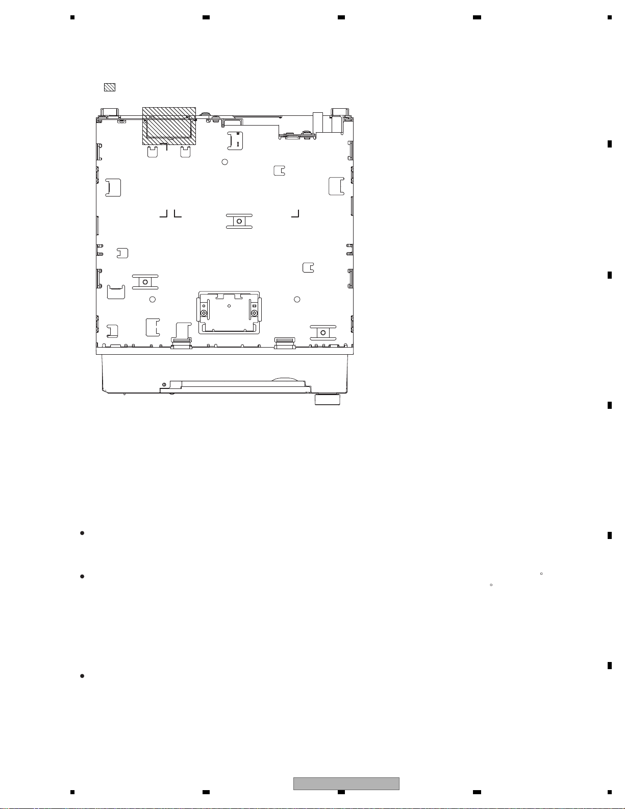
14. area and a heat sink becomes hot areas. Be careful not to burn yourself.
For environmental protection, lead-free solder is used on the printed circuit boards mounted in this unit.
Be sure to use lead-free solder and a soldering iron that can meet specifications for use with lead-free solders for repairs
accompanied by reworking of soldering.
Compared with conventional eutectic solders, lead-free solders have higher melting points, by approximately 40 C.
Therefore, for lead-free soldering, the tip temperature of a soldering iron must be set to around 373 C in general, although
the temperature depends on the heat capacity of the PC board on which reworking is required and the weight of the tip of
the soldering iron.
Compared with eutectic solders, lead-free solders have higher bond strengths but slower wetting times and higher melting
temperatures (hard to melt/easy to harden).
The following lead-free solders are available as service parts:
Parts numbers of lead-free solder:
GYP1006 1.0 in dia.
GYP1007 0.6 in dia.
GYP1008 0.3 in dia.
1.2 NOTES ON SOLDERING
AVH-P6300BT/XNUC
7
Page 8

1234
1234
C
D
F
A
B
E
2. SPECIFICATIONS
General
Power source.............................14.4 V DC (10.8 V to 15.1 V
allowable)
Grounding system...................Negative type
Maximum current consumption
...................................................10.0 A
Dimensions (W ×H× D):
D
Chassis.....................178 mm × 50 mm ×
165mm
(7in. × 2in. × 6-1/2in.)
Nose...........................170 mm ×46 mm ×27 mm
(6-3/4in. ×1-3/4in. ×1in.)
Weight ........................................ 2.2 kg (4.84 lbs)
Display
Screen size/aspect ratio.......7.0 inch wide/16:9
(effective display area:
154.0mm ×86.9mm)
Pixels........................................... 345 600 (1 440 × 240)
Display method .......................TFT activematrix,driving
type
Color system.............................NTSC
Durable temperature range(poweroff)
...................................................–20 °C to +80 °C
Angle adjustment................... 50° to 110°
(initial settings: 90°)
Audio
Maximum power output.......50 W × 4
70 W ×1/2 Ω (for subwoo-
fer)
Continuous power output ...22 W × 4 (1 kHz,5 % THD,4
Ω load, both channelsdri-
ven)
Load impedance..................... 4 Ω (4 Ω to 8 Ω (2 Ω for 1ch)
allowable)
Preout maximumoutputlevel
...................................................4.0 V
Equalizer (8-Band GraphicEqualizer):
Frequency.........................40 Hz/80Hz/200Hz/400 Hz/
1kHz/2.5 kHz/8kHz/10kHz
Gain.................................... ±12 dB
HPF:
Frequency.........................50 Hz/63Hz/80Hz/100 Hz/
125Hz
Slope...................................–12 dB/oct
Subwoofer (mono):
Frequency.........................50 Hz/63Hz/80Hz/100 Hz/
125Hz
Slope...................................–18 dB/oct
Gain.....................................+6 dB to –24 dB
Phase .................................Normal/Reverse
Bass boost:
Gain.....................................+12 dB to 0 dB
DVD Player
System........................................DVD video, Video CD, CD,
WMA, MP3, AAC,DivX,
JPEG system
Usable discs .............................DVD video, Video CD,CD,
CD-R/RW,DVD-R/RW/R DL
Region number ........................1
Frequency response...............5 Hz to 44 000 Hz (with DVD,
at sampling frequency
96kHz)
Signal-to-noise ratio...............96 dB (1 kHz) (IHF-A net-
work) (RCA level)
Output level:
Video...................................1.0 Vp-p/75 Ω (±0.2 V)
Number of channels............. 2 (stereo)
MP3 decoding format ...........MPEG-1 & 2 Audio Layer 3
WMA decoding format .........Ver. 7, 7.1, 8, 9, 10, 11, 12
(2ch audio)
(Windows Media Player)
AAC decoding format ............MPEG-4 AAC (iTunes en-
coded only) (.m4a)
(Ver. 9.0.3 andearlier)
DivX decoding format............Home Theater Ver. 3, 4,5.2,
6 (.avi, .divx)
USB
USB standard specification
...................................................USB 1.1, USB 2.0 full speed
Maximum current supply ....500mA
USB Class..................................MSC (Mass Storage Class)
File system.................................FAT16, FAT32
MP3 decoding format ...........MPEG-1 & 2 Audio Layer 3
WMA decoding format .........Ver. 7, 7.1, 8, 9, 10, 11, 12
(2ch audio)
(Windows Media Player)
AAC decoding format ............MPEG-4 AAC (iTunes en-
coded only)
(Ver. 9.0.3 andearlier)
DivX decoding format............Home Theater Ver.3, 4, 5.2,
6 (.avi, .divx)
SD
Compatible physical format
...................................................Version 1.1
File system.................................FAT12, FAT16, FAT32
MP3 decoding format ...........MPEG-1 & 2 Audio Layer 3
WMA decoding format .........Ver. 7, 7.1, 8, 9, 10, 11, 12
(2ch audio)
(Windows Media Player)
AAC decoding format............MPEG-4 AAC (iTunes en-
coded only)
(Ver. 9.0.3 andearlier)
DivX decoding format............Home Theater Ver. 3,4,5.2,
6 (.avi, .divx)
FM tuner
Frequency range.....................87.9 MHz to 107.9 MHz
Usable sensitivity.................... 9dBf (0.8 µV/75 Ω, mono,
S/N: 30dB)
Signal-to-noise ratio...............72 dB (IHF-A network)
AM tuner
Frequency range.....................530 kHz to 1 710 kHz
(10kHz)
Usable sensitivity.................... 25 µV (S/N: 20dB)
Signal-to-noise ratio...............62 dB (IHF-A network)
Bluetooth
Version.........................................Bluetooth 2.0 certified
Output power ............................+4 dBm Maximum
(Powerclass2)
CEA2006 Specifications
Power output .............................14 W RMS × 4 Channels
(4 Ω and 1 % THD+N)
S/N ratio......................................91 dBA (reference: 1 Winto
4 Ω)
Note
Specifications and the design are subject to modifications without notice.
• AVH-P6300BT/XNUC
Backup current ........................ 5.0 mA or less
<
=
2.1 SPECIFICATIONS
8
AVH-P6300BT/XNUC
Page 9

5678
56
7
8
C
D
F
A
B
E
General
Rated power source...............14.4 V DC
(allowable voltage range:
12.0V to 14.4V DC)
Grounding system.................. Negative type
Maximum current consumption
...................................................10.0 A
Dimensions (W ×H× D):
D
Chassis.....................178 mm × 50 mm ×
165mm
Nose...........................170 mm × 46 mm × 27 mm
Weight ........................................ 2.2 kg
Display
Screen size/aspect ratio.......7.0 inch wide/16:9
(effective display area:
154.0mm × 86.9 mm)
Pixels........................................... 345 600 (1 440 × 240)
Display method .......................TFT activematrix,driving
type
Color system.............................NTSC/PAL/PAL-M/SECAM
compatible
Durable temperature range(poweroff)
...................................................–20 °C to +80 °C
Audio
Maximum power output.......50 W × 4
70 W ×1/2 Ω (for subwoofer)
Continuous power output ...22 W × 4 (1 kHz,5 % THD,4
Ω load, both channelsdriven)
Load impedance..................... 4 Ω (4 Ω to 8 Ω (2 Ω for 1ch)
allowable)
Preout maximumoutputlevel
.................................................. 4.0 V
Equalizer (8-Band GraphicEqualizer):
Frequency........................ 40 Hz/80Hz/200 Hz/400Hz/
1kHz/2.5 kHz/8kHz/10kHz
Gain.................................... ±12 dB
HPF:
Frequency........................ 50 Hz/63Hz/80 Hz/100Hz/
125Hz
Slope.................................. –12 dB/oct
Subwoofer (mono):
Frequency.........................50 Hz/63Hz/80Hz/100 Hz/
125Hz
Slope.................................. –18 dB/oct
Gain.................................... +6 dB to –24 dB
Phase ................................ Normal/Reverse
Bass boost:
Gain.................................... +12 dB to 0 dB
DVD Player
System........................................DVD video, Video CD, CD,
WMA, MP3, AAC,DivX,
JPEG system
Usable discs .............................DVD video, Video CD, CD,
CD-R/RW,DVD-R/RW/R DL
Region number ....................... 4
for South AmericanandOceanian models
Region number ....................... 2
for Middle EastAsian and South African models
Frequency response...............5 Hz to 44 000 Hz (with DVD,
at sampling frequency
96kHz)
Signal-to-noise ratio...............96 dB (1 kHz) (IEC-A net-
work) (RCA level)
Output level:
Video...................................1.0 Vp-p/75 Ω (±0.2 V)
Number of channels ............. 2 (stereo)
MP3 decoding format .......... MPEG-1 & 2 Audio Layer 3
WMA decoding format .........Ver. 7, 7.1, 8, 9, 10, 11, 12
(2ch audio)
(Windows Media Player)
AAC decoding format ............MPEG-4 AAC (iTunes en-
coded only) (.m4a)
(Ver. 9.0.3 andearlier)
DivX decoding format............Home Theater Ver. 3, 4, 5.2,
6 (.avi, .divx)
USB
USB standard specification
...................................................USB 1.1, USB 2.0 full speed
Maximum current supply ....500mA
USB Class..................................MSC (Mass Storage Class)
File system.................................FAT16, FAT32
MP3 decoding format ...........MPEG-1 & 2 Audio Layer 3
WMA decoding format .........Ver. 7, 7.1, 8, 9, 10, 11, 12
(2ch audio)
(Windows Media Player)
AAC decoding format ............MPEG-4 AAC (iTunes en-
coded only)
(Ver. 9.0.3 andearlier)
DivX decoding format............Home Theater Ver. 3, 4, 5.2,
6 (.avi, .divx)
SD
Compatible physical format
...................................................Version 1.10
File system.................................FAT12, FAT16, FAT32
MP3 decoding format ...........MPEG-1 & 2 Audio Layer 3
Backup current ........................ 5.0 mA or less
WMA decoding format .........Ver. 7, 7.1, 8, 9, 10, 11, 12
(2ch audio)
(Windows Media Player)
AAC decoding format............MPEG-4 AAC (iTunes en-
coded only)
(Ver. 9.0.3 andearlier)
DivX decoding format............Home Theater Ver. 3, 4, 5.2,
6 (.avi, .divx)
FM tuner
Frequency range.....................87.5 MHz to 108.0 MHz
Usable sensitivity.................... 9dBf (0.8 µV/75 Ω, mono,
S/N: 30dB)
Signal-to-noise ratio...............72 dB (IEC-A network)
AM tuner
Frequency range.....................531 kHz to 1 602 kHz (9 kHz)
530kHz to 1640 kHz
(10kHz)
Usable sensitivity.................... 25 µV (S/N: 20dB)
Signal-to-noise ratio...............62 dB (IEC-A network)
Bluetooth
Version ........................................Bluetooth 2.0 certified
Output power ...........................+4 dBm Maximum
(Powerclass2)
Infrared remote control
Wavelength................................945 nm
Output ......................................... typ; 10 mw/sr per Infrared
LED
Note
Specifications and the design are subject to modifications without notice.
• AVH-P6350BT/XNRD, XNRI
AVH-P6300BT/XNUC
9
Page 10
1234
1234
C
D
F
A
B
E
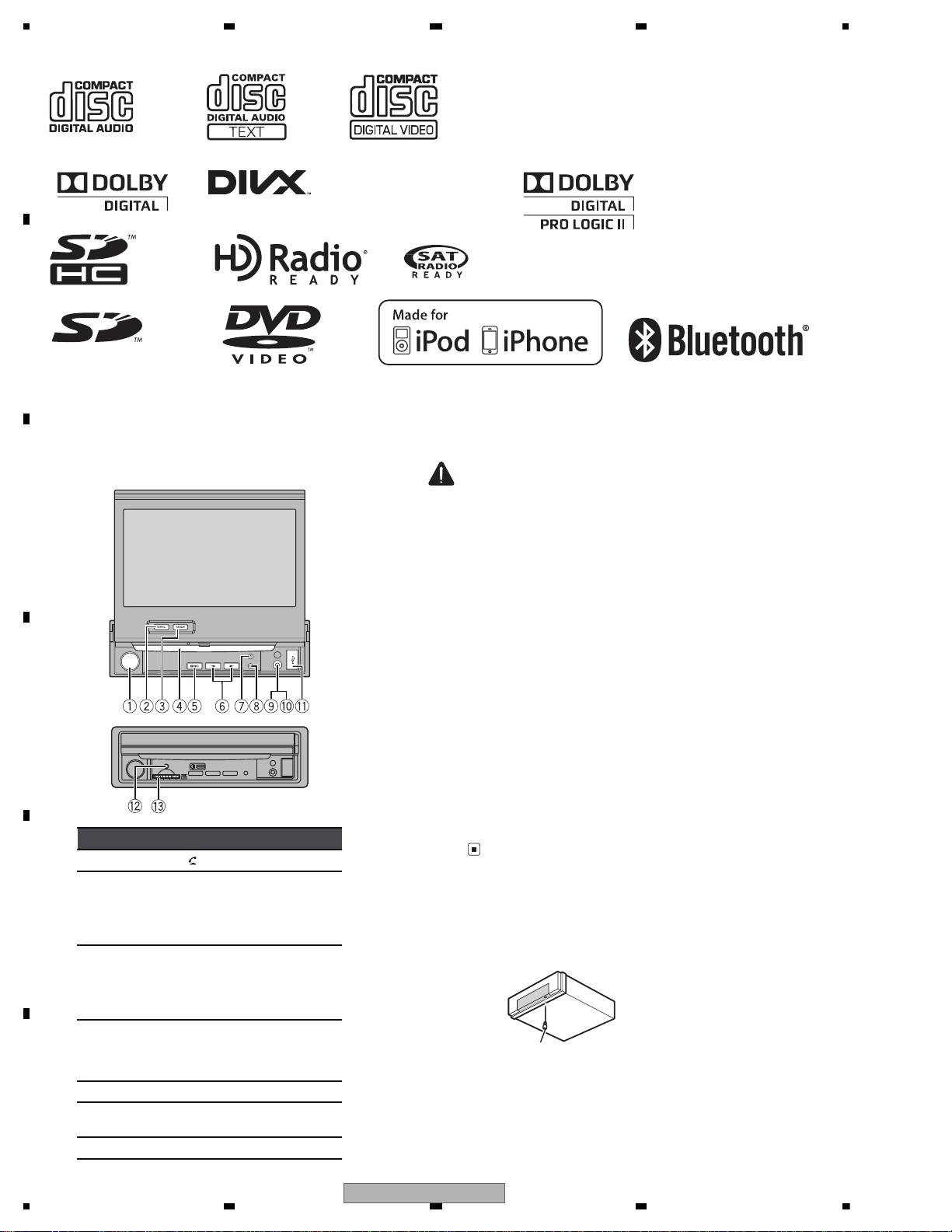
2.2 DISC/CONTENT FORMAT
(UC model)
(UC model)
(UC model)
(RD, RI models))
Head unit
PartPart
1 Volume/ MUTE/
8 OPEN/CLOSE
2
MENU
Displaying the
menu.
Returning to the
normal display.
9
AUX input jack
(3.5mm stereo/
video jack)
Use to connectan
auxiliary device.
3
MODE
Turningthe information display off.
a
Auto EQ microphone input jack
Use to connectan
auto EQ microphone.
4 Disc loading slot b
USB port
When connecting,
open the USBconnector lid.
5 SRC/OFF c RESET
6
/(TRACK/
SEEK)
d
SD memory card
slot
7 (eject)
CAUTION
Use an optional PioneerUSBcable(CD-U50E)
to connect the USB audio player/USB memory as any device connected directly to the
unit will protrude out from the unit and may
be dangerous.
Do not use unauthorized products.
Notes
Insert it with the contact surface facing down,
and press on the card until it clicks and completely locks into place.
When the navigation system is connected,
press MODE to switch to the navigation display.Press MODE andhold to turn the display
off.
Press MODE again to turnthedisplayon.
Press and hold MENU to display
Picture Adjustment.
Refer to Changing the picture adjustment.
For detailsonhowtooperateanavigationsys-
tem from this unit, refer to its operation manual.
Fastening the front panel
If you do not plan to detach the front panel,
the front panel can be fastened with supplied
screw.
Screw
UC : BPZ20P060FTC
• AVH-P6300BT/XNUC
2.3 PANEL FACILITIES
10
AVH-P6300BT/XNUC
Page 11
5678
56
7
8
C
D
F
A
B
E
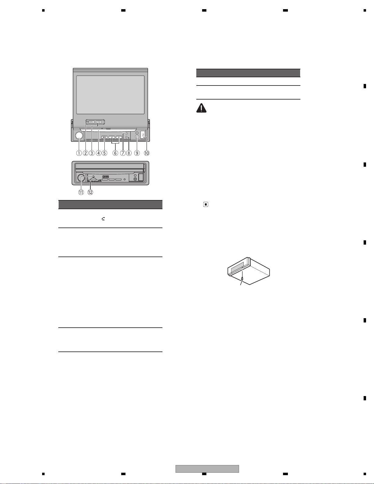
Head unit
PartPart
1
Volume/MUTE/
7 (eject)
2
MENU
Displaying the
menu.
Returning to the
normal display.
8 OPEN/CLOSE
3
MODE
Turningthe information display off.
9
AUX input jack
(3.5mm stereo/
video jack)
Use to connect
an auxiliary device.
Auto EQ micro-
phone input
jack
Use to connect
an auto EQmicrophone.
4 Disc loading slot a
USB port
When connecting,
open the USBconnector lid.
traPtraP
5 SRC/OFF b RESET
6
/(TRACK/
SEEK)
c
SD memory card
slot
CAUTION
Use an optional PioneerUSBcable(CD-U50E)
to connect the USB audio player/USB memory as any device connected directly to the
unit will protrude out from the unit and may
be dangerous.
Do not use unauthorized products.
Notes
Insert an SD memory card with the contact
surface facing down, and press on the card
until it clicks and completely locks into place.
Press and hold MENU to display
Picture Adjustment.
Refer to Changing the picture adjustment.
Fastening the front panel
If you do not plan to detach the front panel,
the front panel can be fastened with supplied
screw.
Screw
RD, RI : XXX7020
• AVH-P6350BT/XNRD, XNRI
AVH-P6300BT/XNUC
11
Page 12
1234
1234
C
D
F
A
B
E
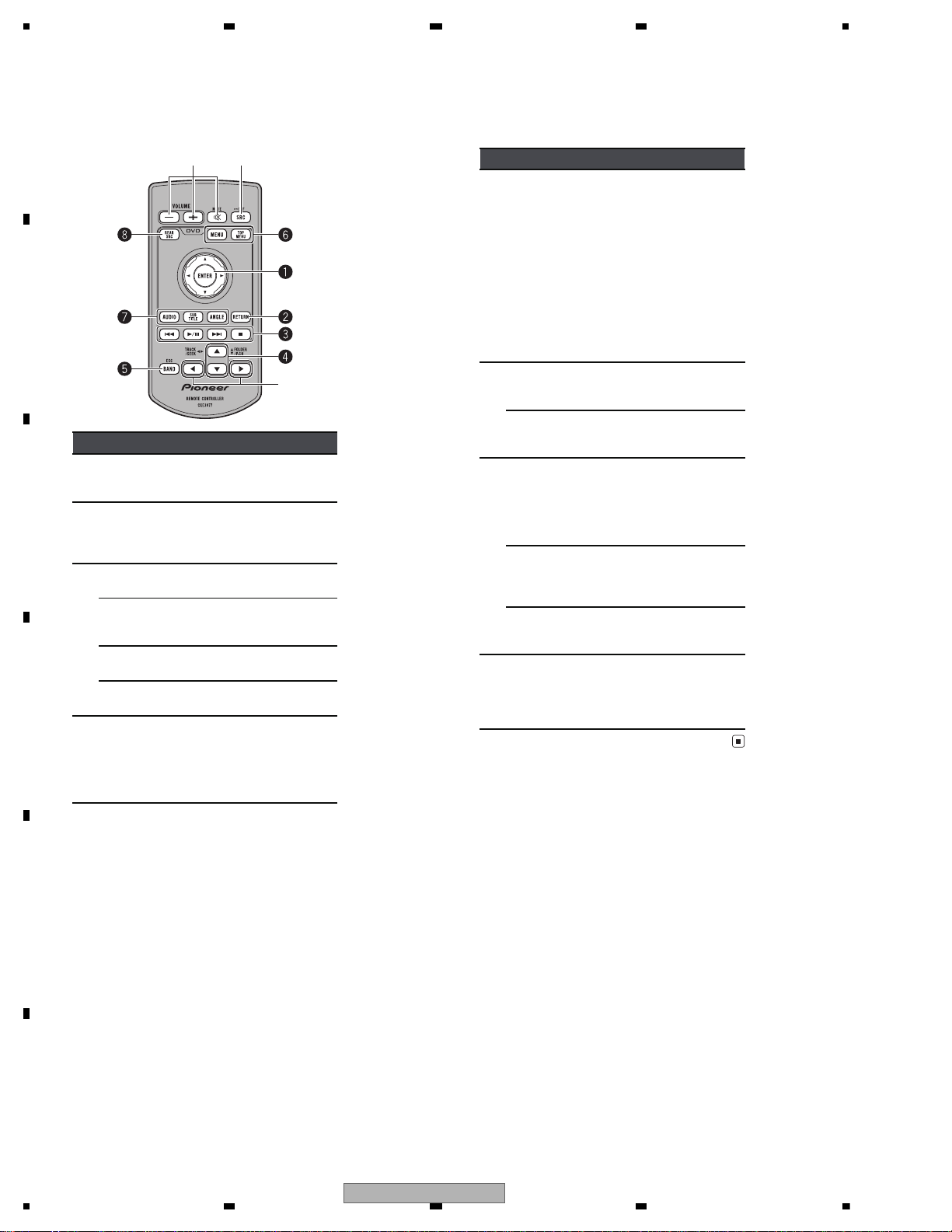
Remote control
1 5
6
Part Operation
1 Thumb pad
Click to recall Menu.
Use to selectamenu
on the DVDmenu.
2 RETURN
Press todisplay the
PBC (playback control) menu duringPBC
playback.
3
Press topause or resume playback.
Press toreturn to the
previous track (chapter).
Press togo to the next
track (chapter).
Press tostop playback.
4 /(FOLDER/P.CH)
Press toselect the
next/previous folder.
Press torecall radio
station frequencies assigned to presettuning keys.
Part Operation
5 BAND/ESC
Press toselect the
tuner band when
tuner is selectedasa
source. Also usedto
cancel the control
mode of functions.
Press toswitch between modes when
playing discs with
compressed audio
and audio data(CDDA) such asCDEXTRA and MIXEDMODE CDs.
6
MENU
Press todisplay the
DVD menu during
DVD playback.
TOP MENU
Press toreturn to the
top menu duringDVD
playback.
7
AUDIO
Press tochange the
audio language during
DVD playback.
Press toswitch audio
output for VideoCD/
DivX.
SUBTITLE
Press tochange the
subtitle language during DVD/DivX playback.
ANGLE
Press tochange the
viewing angle during
DVD playback.
8 REAR SRC
Press tocycle through
all the availablerear
sources.
Press andhold to turn
the rear sourceoff.
12
AVH-P6300BT/XNUC
Page 13
5678
56
7
8
C
D
F
A
B
E
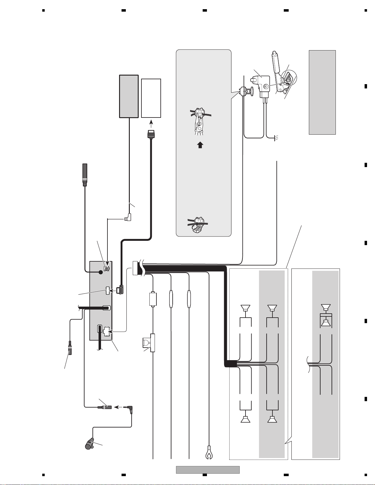
Connecting the power cord
This product
Microphone
(supplied)
4 m
(13 ft. 1 in.)
Fuse (10 A)
RGB input
Wired remote input (WIRED REMOTE INPUT)
Hard-wired remote control adaptor can be
connected (sold separately).
Microphone input Jack (MIC)
17 cm (6-3/4 in.)
17 cm (6-3/4 in.)
Yellow
Connect to the constant 12 V supply terminal.
Fuse resistor
Red
Connect to terminal controlled by ignition switch (12 V DC).
Black (chassis ground)
Connect to a clean, paint-free metal location.
Left Right
Front speakerFront speaker
Rear speaker or
Subwoofer (4 Ω)
White Gray
Gray/blackWhite/black
Green Violet
Green/black Violet/black
Violet
Violet/black
Not used.
Green
Green/black
When using a subwoofer of 70 W (2 Ω), be sure to connect with Violet and Violet/black leads of this unit.
Do not connect anything to Green and Green/black leads.
Subwoofer (4 Ω)
× 2
Rear speaker or
Subwoofer (4 Ω)
Orange/white
Connect to lighting switch terminal.
Fuse resistor
Pioneer IP-BUS
accessories
Navigation system
(AVIC-U220 (sold
separately)).
Antenna input
IP-BUS cable
IP-BUS input
(Blue)
26 pin cable (Supplied with Navigation system)
Insert the 26 pin cable in the direction
indicated in the figure.
Please contact your dealer to inquire
about the connectable navigation system.
Connection method
1. Clamp the lead.
2. Clamp firmly with
needle-nosed pliers.
Note:
· The position of the parking brake switch depends on the vehicle model. For details,
consult the vehicle Owner’s Manual or dealer.
Light green
Used to detect the ON/OFF status of the parking
brake. This lead must be connected to the power
supply side of the parking brake switch.
Blue/white
Connect to system control terminal of the power amp or
auto-antenna relay control terminal (max. 300 mA 12 V DC).
Ground side
Power supply side
Parking brake
switch
With a 2 speaker system, do not connect anything to the speaker leads
that are not connected to speakers.
Note:
· Change the initial setting of this unit. The
subwoofer output of this unit is monaural.
• AVH-P6300BT/XNUC
2.4 CONNECTION DIAGRAM
AVH-P6300BT/XNUC
13
Page 14
1234
1234
C
D
F
A
B
E
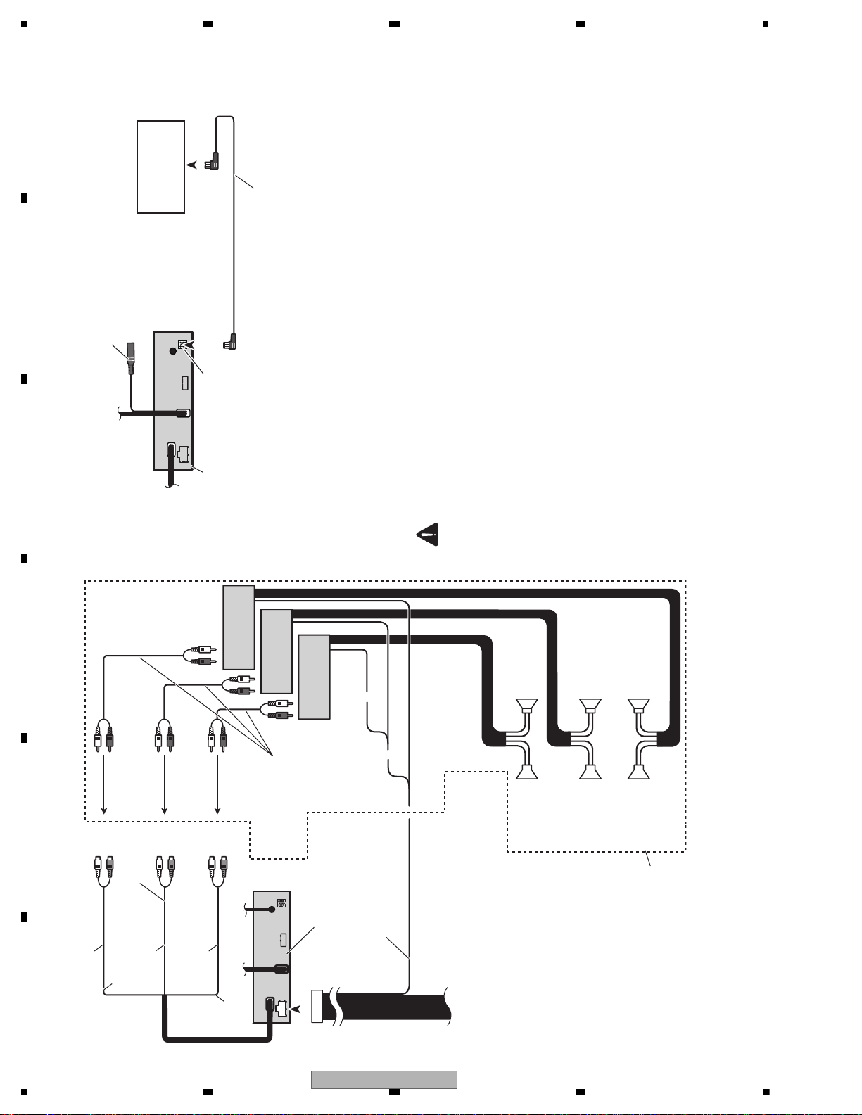
When connecting to separately sold power amp
Blue/white
Connect to system control
terminal of the power amp
(max. 300 mA 12 V DC).
Connect with RCA cables
(sold separately)
Rear speaker
Perform these connections when
using the optional amplifier.
System remote control
Front speaker Front speaker
RightLeft
Rear speaker
Power amp
(sold separately)
Power amp
(sold separately)
Power amp
(sold separately)
Subwoofer
Subwoofer
To front
output
To rear
output
To subwoofer
output
This product
Rear output
(REAR OUTPUT)
Front output
(FRONT OUTPUT)
Subwoofer output
(SUBWOOFER OUTPUT)
13 cm (5-1/8 in.)
17 cm (6-3/4 in.)
13 cm (5-1/8 in.)
Connecting the system
This product
Wired remote input (WIRED REMOTE INPUT)
Hard-wired remote control adaptor can be
connected (sold separately).
IP-BUS input
HD Radio tuner
(sold separately)
IP-BUS cable
(Supplied with HD Radio tuner)
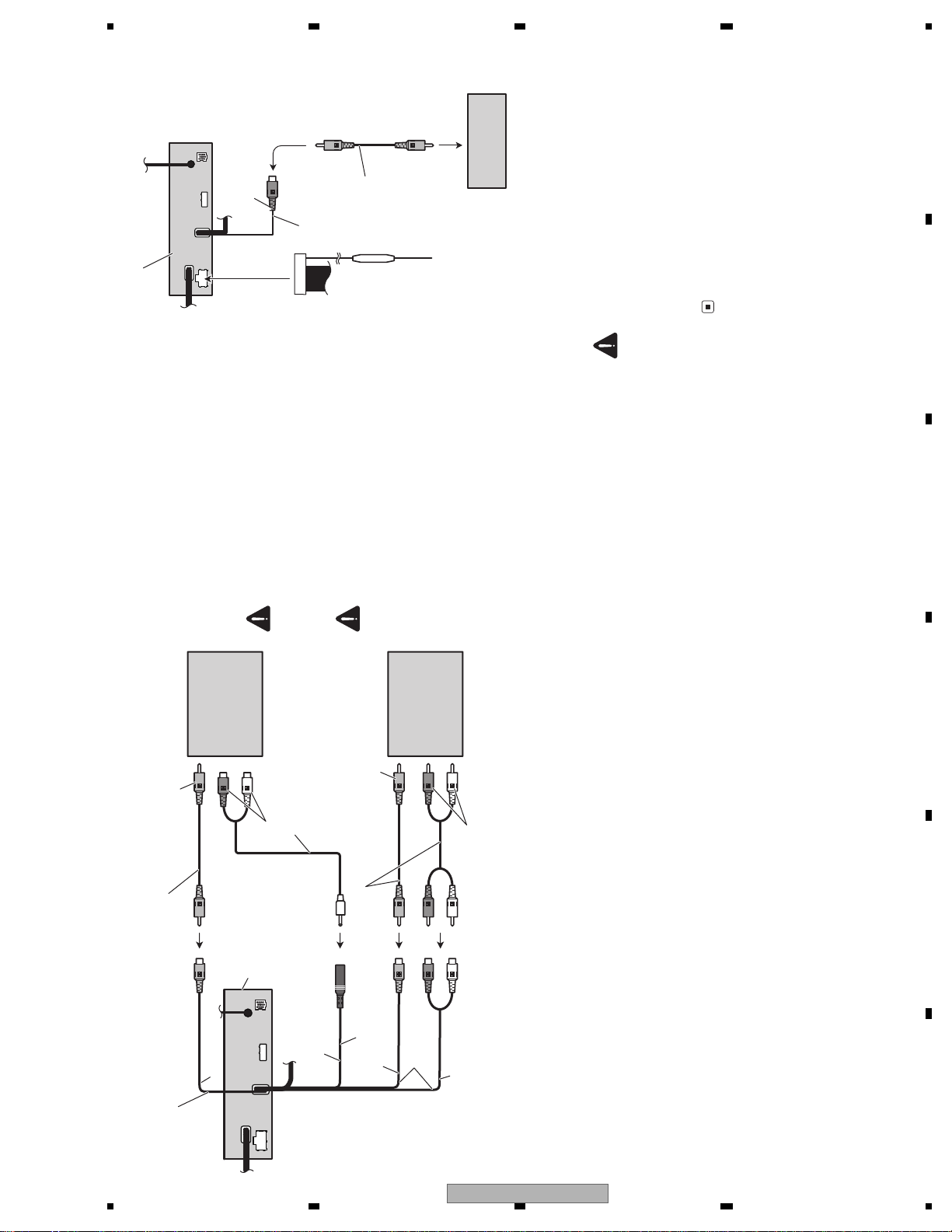
When connecting the external video component and the display
When using a display connected to rear video output
This product’s rear video output and rear
audio output are for connection of a display to
enable passengers in the rear seats to watch
the DVD, etc.
WARNING
Never install the display in a location where it
is visible to the driver while driving.
14
AVH-P6300BT/XNUC
Page 15
5678
56
7
8
C
D
F
A
B
E
This product
External video
component (sold
separately)
RCA cables (sold separately)
Audio inputs
(AUDIO INPUT)
Video input (VIDEO INPUT)
Display with RCA
input jacks (sold
separately)
Rear monitor output
(REAR MONITOR OUTPUT)
To video input
To video output
To audio outputs
13 cm (5-1/8 in.)
Rear audio output
(REAR MONITOR OUTPUT(AUDIO))
To audio inputs
RCA cables (sold separately)
17 cm (6-3/4 in.)
Mini pin plug cable
(sold separately)
13 cm (5-1/8 in.)
It is necessary to change AV Input in
System Menu when connecting the exter-
nal video component.
When connecting with a rear
view camera
When this product is used with a rear view
camera, it is possible to automatically switch
from the video to rear view image when the
gear shift is moved to REVERSE (R).
WARNING
USE INPUT ONLY FOR REVERSE OR MIR-
ROR IMAGE REAR VIEW CAMERA. OTHER
USE MAYRESULT IN INJURY OR DAMAGE.
CAUTION
The screen image may appear reversed.
The rear view camera function is to be used
as an aid to keep an eye on trailers, or while
backing up. Do not use for entertainment pur-
poses.
Objects in the rear view may appear closer or
more distant than they actually are.
Rear view camera input
(REAR VIEW CAMERA IN)
This product
13 cm (5-1/8 in.)
To video output
Rear view camera
(sold separately)
Violet/white
Of the two lead wires
connected to the back lamp,
connect the one in which the
voltage changes when the
gear shift is in the REVERSE
(R) position. This connection
enables the unit to
sense whether the car is
moving forwards or
backwards.
Fuse resistor
RCA cable
(sold separately)
CAUTION
You must use a camera which outputs mirror
reversed images.
It is necessary to set Camera Polarity properly in
System Menu when connecting the rear view
camera.
AVH-P6300BT/XNUC
15
Page 16

1234
1234
C
D
F
A
B
E
Connecting the power cord
This product
Microphone input Jack (MIC)
Microphone (supplied)
4 m
Fuse (10 A)
RGB input
Wired remote input (WIRED REMOTE INPUT)
Hard-wired remote control adaptor can be
connected (sold separately).
17 cm
17 cm
Yellow
Connect to the constant 12 V supply terminal.
Fuse resistor
Red
Connect to terminal controlled by ignition switch (12 V DC).
Black (chassis ground)
Connect to a clean, paint-free metal location.
Left Right
Front speakerFront speaker
Rear speaker or
Subwoofer (4 Ω)
White Gray
Gray/blackWhite/black
Green Violet
Green/black Violet/black
Violet
Violet/black
Not used.
Green
Green/black
When using a subwoofer of 70 W (2 Ω), be sure to connect with Violet and Violet/black leads of this unit.
Do not connect anything to Green and Green/black leads.
Subwoofer (4 Ω)
× 2
Rear speaker or
Subwoofer (4 Ω)
Orange/white
Connect to lighting switch terminal.
Fuse resistor
Pioneer IP-BUS
accessories
Antenna input
IP-BUS cable
IP-BUS input
(Blue)
Connection method
1. Clamp the lead.
2. Clamp firmly with
needle-nosed pliers.
Note:
· The position of the parking brake switch depends on the vehicle model. For details,
consult the vehicle Owner’s Manual or dealer.
Light green
Used to detect the ON/OFF status of the parking
brake. This lead must be connected to the power
supply side of the parking brake switch.
Blue/white
Connect to system control terminal of the power amp or
auto-antenna relay control terminal (max. 300 mA 12 V DC).
Ground side
Power supply side
Parking brake
switch
With a 2 speaker system, do not connect anything to the speaker leads
that are not connected to speakers.
Note:
· Change the initial setting of this unit. The
subwoofer output of this unit is monaural.
When you connect the separately sold multi-channel
processor (e.g.,DEQ-P6600/DEQ-P7650) to this unit,
do not connect anything to the speaker leads and
system remote control (blue/white).
• AVH-P6350BT/XNRD, XNRI
16
AVH-P6300BT/XNUC
Page 17
5678
56
7
8
C
D
F
A
B
E
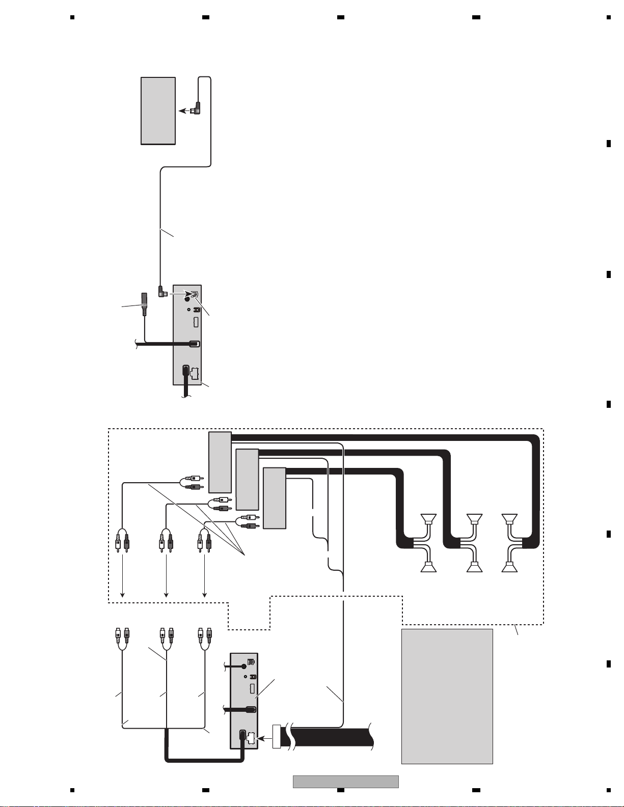
When connecting to separately sold power amp
Blue/white
Connect to system control
terminal of the power amp
(max. 300 mA 12 V DC).
Connect with RCA cables
(sold separately)
Rear speaker
Perform these connections when
using the optional amplifier.
System remote control
Front speaker Front speaker
thgiRtfeL
Rear speaker
Power amp
(sold separately)
Power amp
(sold separately)
Power amp
(sold separately)
Subwoofer
Subwoofer
To front
output
To rear
output
To subwoofer
output
This product
Rear output
(REAR OUTPUT)
Front output
(FRONT OUTPUT)
Subwoofer output
(SUBWOOFER OUTPUT)
13 cm
17 cm
13 cm
•When you connect the separately sold
multi-channel processor
(e.g.,DEQ-P6600/DEQ-P7650) to this
unit, do not connect anything to the
speaker leads and system remote control
(blue/white).
•When you connect the multi-channel
processor to this unit, refer to
multi-channel processor’s installation
manual for the connection method.
Connecting the system
DVD changer
(sold separately)
This product
Wired remote input (WIRED REMOTE INPUT)
Hard-wired remote control adaptor can be
connected (sold separately).
IP-BUS input
IP-BUS cable
AVH-P6300BT/XNUC
17
Page 18
1234
1234
C
D
F
A
B
E
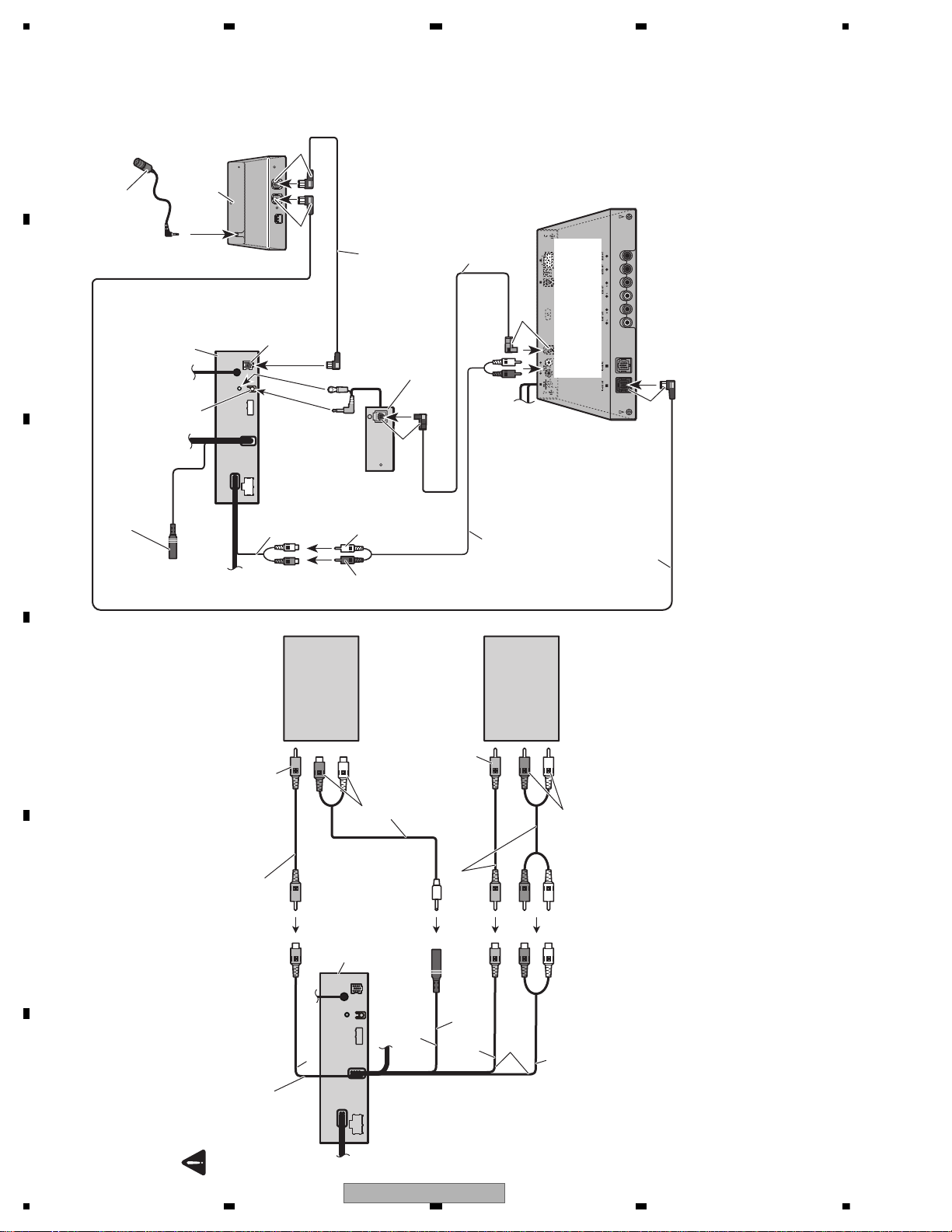
When connecting the external video component and the display
When using a display connected to rear video output
This product’s rear video output and rear
audio output are for connection of a display to
enable passengers in the rear seats to watch
the DVD, etc.
WARNING
Never install the display in a location where it
is visible to the driver while driving.
This product
External video
component (sold
separately)
RCA cables (sold separately)
Audio inputs
(AUDIO INPUT)
Video input (VIDEO INPUT)
Display with RCA
input jacks (sold
separately)
Rear monitor output
(REAR MONITOR OUTPUT)
To video input
To video output
To audio outputs
13 cm
Rear audio output
(REAR MONITOR OUTPUT(AUDIO))
To audio inputs
RCA cables (sold separately)
17 cm
Mini pin plug cable
(sold separately)
13 cm
It is necessary to change AV Input in
System Menu when connecting the exter-
nal video component.
When connecting with a multi-channel processor
IP-BUS cable (supplied with
multi-channel processor)
RCA cable (supplied with
multi-channel processor)
Optical cable
(supplied with
multi-channel processor)
IP-BUS cable
(Supplied with Bluetooth adapter)
Black
Bluetooth adapter
(e.g. CD-BTB200)
(sold separately)
(AVH-P5350DVD only)
Microphone
for hands-free phoning
(supplied with Bluetooth adapter)
Black
Optical cable connection box (CD-DD25)
(DEQ-P6600 :supplied with multi-channel processor)
(DEQ-P7650 : sold separately)
To SWL
To SWR
Blue
Blue
Multi-channel processor
(DEQ-P6600/DEQ-P7650)
(sold separately)
This product
IP-BUS input
Black
Wired remote input (WIRED REMOTE INPUT)
Hard-wired remote control adaptor can be
connected (sold separately).
Subwoofer output
(SUBWOOFER OUTPUT or
NON-FADING OUTPUT)
Optical
output
18
AVH-P6300BT/XNUC
Page 19
5678
56
7
8
C
D
F
A
B
E
When connecting with a rear
view camera
When this product is used with a rear view
camera, it is possible to automatically switch
from the video to rear view image when the
gear shift is moved to REVERSE (R).
WARNING
USE INPUT ONLY FOR REVERSE OR MIR-
ROR IMAGE REAR VIEW CAMERA. OTHER
USE MAYRESULT IN INJURY OR DAMAGE.
CAUTION
The screen image may appear reversed.
The rear view camera function is to be used
as an aid to keep an eye on trailers, or while
backing up. Do not use for entertainment pur-
poses.
Objects in the rear view may appear closer or
more distant than they actually are.
Rear view camera input
(REAR VIEW CAMERA IN)
This product
13 cm
To video output
Rear view camera
(sold separately)
Violet/white
Of the two lead wires
connected to the back lamp,
connect the one in which the
voltage changes when the
gear shift is in the REVERSE
(R) position. This connection
enables the unit to
sense whether the car is
moving forwards or
backwards.
Fuse resistor
RCA cable
(sold separately)
CAUTION
You must use a camera which outputs mirror
reversed images.
It is necessary to set Camera Polarity properly in
System Menu when connecting the rear view
camera.
Connecting and installing the
optical cable connection box
WARNING
Avoid installing the optical cable connection
box in locations where the operation of safety
devices such as airbags is prevented by this
unit. Otherwise, there is a danger of a fatal ac-
cident.
Avoid installing the optical cable connection
box in locations where the operation of the
brake may be prevented. Otherwise, it may re-
sult in a traffic accident.
Fix the optical cable connection box securely
with the hook and loop fastener or lock tie. If
the unit is loose, it disturbs driving stability,
which may result in a traffic accident.
CAUTION
Install this unit using only the parts supplied
with this unit. If other parts are used, this unit
may be damaged or could dismount itself,
which leads to an accident or other problems.
Do not install this unit near the doors where
rainwater is likely to be spilled on the unit. In-
cursion of water into the unit may cause
smoke or fire.
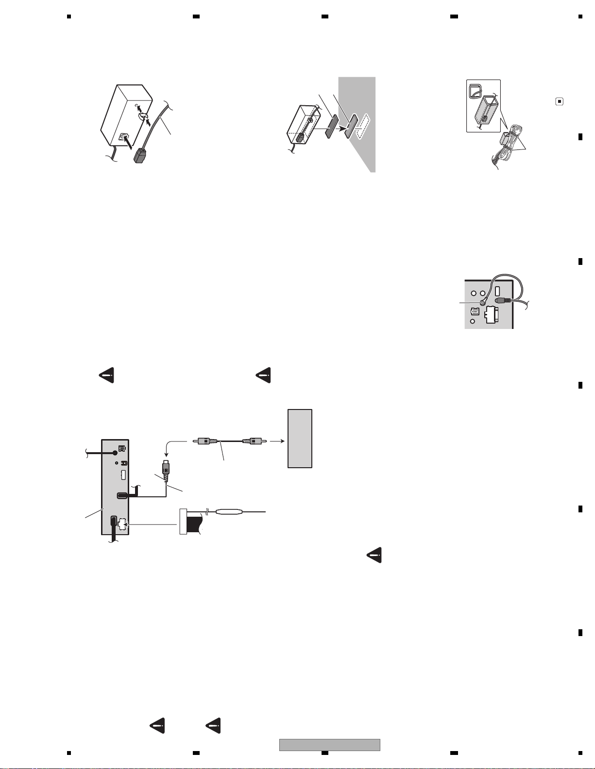
Connecting the optical cable
1 Connect the optical cable and ground
lead to the main unit.
Connect the optical cable so that it does not
protrude from the main unit, as shown in the
illustration. Fasten the ground lead to the pro-
trusion on the back of the main unit.
1
1 Screw
2 Connect the optical cable to the optical
cable connection box.
1
1 Optical cable
Installing the optical cable
connection box
When installing the optical cable con-
nection box with the hook and loop fasten-
er.
Install the optical cable connection box using
the hook and loop fastener in the ample space
of the console box.
1
2
1 Hook fastener
2 Loop fastener
When installing the optical cable con-
nection box with the lock tie.
Wrap the optical cable and connection box
with the protection tape and fasten with the
power code using the lock tie.
1
2
1 Wrap with the protectiontape
2 Fastenwiththelocktie
AVH-P6300BT/XNUC
19
Page 20
1234
1234
C
D
F
A
B
E
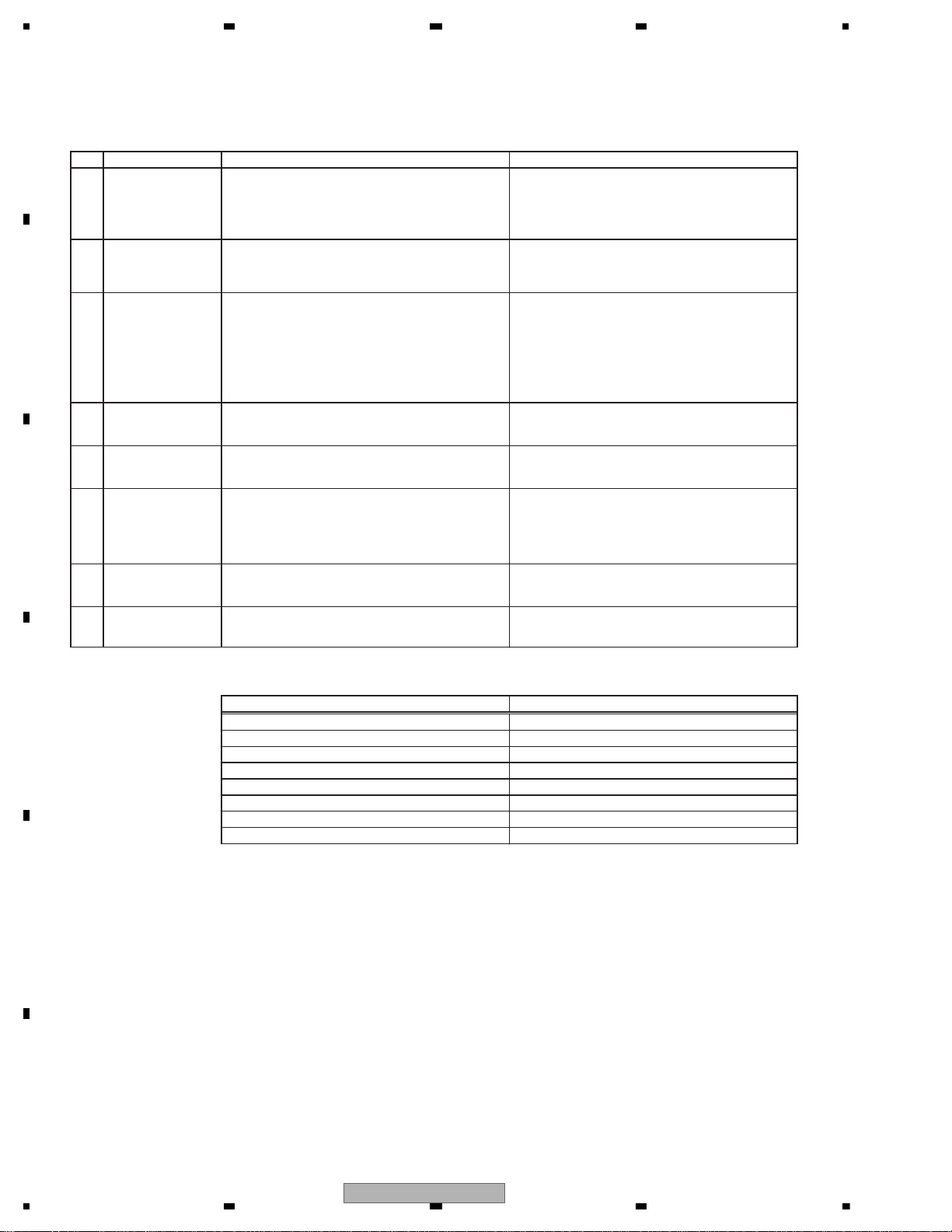
3. BASIC ITEMS FOR SERVICE
To keep the product quality after servicing, please confirm following check points.
No. Procedures Item to be confirmed
1 Confirm whether the customer complain has
been solved.
If the customer complain occurs with the
specific media, use it for the operation check.
The customer complain must not be
reappeared.
Display, video, audio and operations must be
normal.
3 DVD Measure playback error rates at the
innermost and outermost tracks by using the
test mode with the following disc.
DVD test disc (TDV-582)
Deterioration of mecha-drive can be
checked.
The error rate must be less than the
threshold value.
(Refer to the chapter of DIAGNOSIS for the
threshold value.)
4 DVD Play back a DVD.
(Menu operation; Title/chapter search)
Display, video, audio and operations must be
normal.
5 CD Play back a CD.
(Track search)
Display, audio and operations must be
normal.
6 FM/AM tuner Check FM/AM tuner action.
(Seek, Preset)
Switch band to check both FM and AM.
Display, audio and operations must be
normal. * If the reception sensitivity is poorer
than normal, the gasket on the FM/AM tuner
unit may be damaged or lost.
7 Check whether no disc is inside the product. The media used for the operating check must
be ejected.
8 Appearance check No scratches or dirt on its appearance after
receiving it for service.
For check items concerning image and voice, please refer to the followings:
Check items concerning image Check items concerning voice
Block-noise Distortion
Crosscut noise Noise
Dot noise Low volume
Distorted image (Image skip) High volume
Low brightness Changes in level
Too bright Pause of sound
Color fading
Partial discoloration
2 Flap-mecha Check the operation of the flap mechanism. The flap mechanism operation must be
smooth without making the noise and
scratches.
3.1 CHECK POINTS AFTER SERVICING
20
AVH-P6300BT/XNUC
Page 21
5678
56
7
8
C
D
F
A
B
E
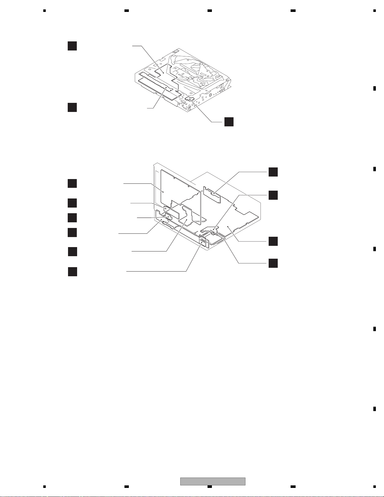
3.2 PCB LOCATIONS
DVD Core Unit
C
(MS7)
Compound Unit (A)
D
Monitor PCB
K
Keyboard PCB
G
Switch PCB Unit
I
Compound Unit (B)
E
B
J
Tuner PCB
Volume PCB Unit
F
Panel PCB
Main PCB Unit
H
BT ANT PCB
M
A:AVH-P6300BT/XNUC
B:AVH-P6350BT/XNRD
C:AVH-P6350BT/XNRI
DVD Amp Unit(Service)
Consists of
Mother PCB
Tuner PCB
Unit Number : CXX3036(A)
: CXX3037(B)
: CXX3038(C)
Unit Name : DVD Amp Unit(Service)
Unit Number : YWX5010
Unit Name : DVD Core Unit(MS7)
Unit Number : CWX3864
Unit Name : Compound Unit(A)
Unit Number : CWX3559
Unit Name : Compound Unit(B)
Keyboard Unit
Consists of
Panel PCB
Keyboard PCB
Unit Number :
Unit Name : Keyboard Unit
Mother PCB
A
BT PCB
L
Unit Number :
Unit Name : Main PCB Unit
Unit Number :
Unit Name : Switch PCB Unit
Unit Number :
Unit Name : Volume PCB Unit
Monitor Unit
Consists of
Monitor PCB
BT PCB
BT ANT PCB
Unit Number : (A)
: (B)
: (C)
Unit Name : Monitor Unit
AVH-P6300BT/XNUC
21
Page 22
1234
1234
C
D
F
A
B
E
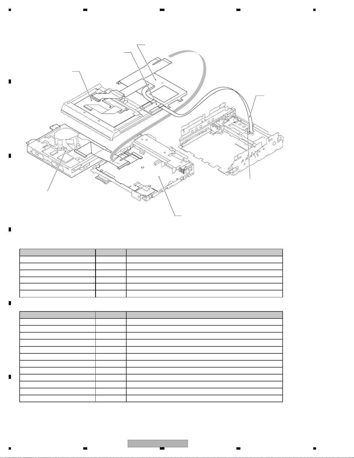
3.3 JIGS LIST
Drive Unit
GGF1461
40-Pin + 20-Pin
Extension Board
GGD1209
20-Pin FFC
DVD Mechanism Module
Bracket
Monitor Unit
DVD Amp Unit
- Grease List
Bond GEM1033 DVD Mechanism Module
Bond GEM1068 DVD Mechanism Module
Name Jig No. Remarks
Grease GEM1038 DVD Mechanism Module
Grease GEM1045 DVD Mechanism Module
Grease GEM1050 DVD Mechanism Module
Grease GEM1085 DVD Mechanism Module
Grease GEM1024 DVD Mechanism Module and Drive Unit
Grease GEM1043 DVD Mechanism Module and Drive Unit
Grease GEM1011 Drive Unit
Grease GEM1047 Drive Unit
Grease GEM1071 Drive Unit
Grease GEM1072 Drive Unit
- Jigs List
Name Jig No. Remarks
DVD-Video GGV1025 Inspection method of pickup unit and skew adjustment
CD-DA TCD-782 Inspection method of pickup unit
Torques (T2) driver GGK1095 Skew adjustment
20P FFC GGD1209 Drive Unit <--> 40P+20P Extension Board
40P+20P Extension Board GGF1461 Drive Unit (Only 20P side is used.)
GGF1539 Disassembly
22
AVH-P6300BT/XNUC
Page 23

5678
56
7
8
C
D
F
A
B
E
Before shipping out the product, be sure to clean the following portions by using the prescribed cleaning tools:
Portions to be cleaned Cleaning tools
DVD pickup lenses Cleaning liquid : GEM1004
Cleaning paper : GED-008
Portions to be cleaned Cleaning tools
Fans Cleaning paper : GED-008
3.4 CLEANING
AVH-P6300BT/XNUC
23
Page 24
1234
1234
C
D
F
A
B
E
4. BLOCK DIAGRAM
Note: When ordering service parts, be sure to refer to " EXPLODED VIEWS AND PARTS LIST" or
"ELECTRICAL PARTS LIST".
CN331
CKS4497-A
11
CCAUR12GNDAU
14
ONSEI-
15
REAUR16REAUL
17
GNDRAU
18
CCREM
19
DSEN20TVON
21GION
22
MONON
23
VSW5
24
SYS_TO_NAVI
25
NAVI_TO_SYS
26
GNDD
13
ONSEI+
JA481
CKN1050-A
4
312
JA301
CKS3414-A
1
BUS+2BUSG
3
BUSLG
4
MAINTEST
5
BUS-
6
BUSRG
7
BUSL+
8
ASENBO
9
BUSR+
10
BUSR-11BUSL-
CKS5543-A
CN2001
1
ANGLE
2
LIFTPUL
3
MTRS
4
MTRPW
5
MTR2
6
MTR1
7
MTRSEL
8
ANGL0SW
9
LFTSW
10
SENSPW
11
VDD
12
NC
13
GNDD
14
GND
15
GND
16
GND
17
NC
18
BUP
19
BUP
20
BUP
CKS5732-A
CN2021
1
TEMP1
2
DIMPLS
3
MBLPW
4
BLCLK
5
BLERR1
6
PWRBL
7
PWRBL
8
PWRBL
9
NC
10
GNDBL
11
GNDBL
12
GNDBL
13
MOVBS
14
VGND
15
ANAB
16
CSYNC
17
ANAR
18
ANAG
19
VGND
20
GRST
21
GtoS
22
StoG
23
DGCLK
24
GtoD
25
DtoG
26
NC
27
ILMB
28
NC
29
GNDILM
30
NC
31
KDT1
32
NC
33
NC
34
GNDKEY
35
GNDKEY
36
ILB
37
ILG
38
ILR
39
PLYV
40
PLXV
41
ADVX
42
ADVY
43
PWGR
44
GNDD
45
GNDD
46
GNDD
47
NC
48
PWRVI
49
PWRVI
50
PWRVI
CKS6180-A
CN961
1
CD/DAT3
3
VSS1
5
CLK
7
DAT0
9
DAT2
11
GND2
13
CD/WP
14
WP
12
CD
10
GND1
8
DAT1
6
VSS2
4
VDD
2
CMD
15
NC1
16
NC2
17
GND3
18
GND4
19
GND5
20
GND6
REMIN
VCC33NCAUX_L
AUX_AGND
12345
CKS5858-A
CN3001
REMIN
VCC33
NC
AUX_L
AUX_AGND
12345
CKS6008-A
CN5002
PWRVI
1
PWRVI
2
PWRVI
3
NC
4
GNDD
5
GNDD
6
GNDD
7
PWGR
8
ADVY
9
ADVX
10
PLXV
11
PLYV
12
ILR
13
ILG
14
ILB
15
GNDKEY
16
GNDKEY
17
NC
18
NC
19
KEY1
20
NC
21
GNDILM
22
NC
23
ILMB
24
NC
25
DtoG
26
GtoD
27
DGCLK
28
StoG
29
GtoS
30
GRST
31
VGND
32
ANAG
33
ANAR
34
CSYNC
35
ANAB
36
VGND
37
MOVBS
38
GNDBL
39
GNDBL
40
GNDBL
41
NC
42
PWRBL
43
PWRBL
44
PWRBL
45
BLERR1
46
BLCLK
47
MBLPW
48
DIMPLS
49
TEMP1
50
CKS6062-A
CN5601
GND
1
GND
2
GND
3
NC
4
VCC
5
VCC
6
VCC
7
VCC
8
NC
9
TEST
10
TEST
11
TEST
12
VSYNC
13
HSYNC
14
GND
15
SHUT
16
GND
17
R5
18
R4
19
R3
20
R2
21
R1
22
R0
23
GND
24
G5
25
G4
26
G3
27
G2
28
G1
29
G0
30
GND
31
B5
32
B4
33
B3
34
B2
35
B1
36
B0
37
GND
38
DCLK
39
GND
40
CKS5695-A
CN5802
GNDKEY
1
ILMB
2
KEY1
3
LEDR1
4
LEDG1
5
LEDB1
6
CKS5561-A
CN5701
LED41LED32LED23LED14NC5BLP6BLP7NC8TEMP19GNDD
10
CKS5561-A
CN5101
NC
1
PLYV2PLYV3PLXV4PLXV5ADVX6ADVX7ADVY8ADVY
9
NC
10
JA3001
CKN1084-A
NAVI INTER
OUT
S/PDIF
IP-BUS
SD CARD
AUX
LCD MODULE
BACK LIGHT
TOUCH PANEL
ANAL
1/5
A
I/F PA
5/5
A
POW
3/5
A
JH I
DRIVE UNIT
F
G
KEYBOARD PCB
A
MOT
MMD
4/5
SYST
2/5
A
A
MONITOR PART
1/2
K
K
MONITOR PCB
BACKLIGHT PART
2/2
K
CN101
CN3500
MONITOR UNIT
Consists of
MONITOR PCB
BT PCB
BT ANT PCB
KEYBOARD UNIT
Consists of
PANEL PCB
KEYBOARD PCB
only B, C
A : AVH-P6300BT/XNUC
B : AVH-P6350BT/XNRD
C : AVH-P6350BT/XNRI
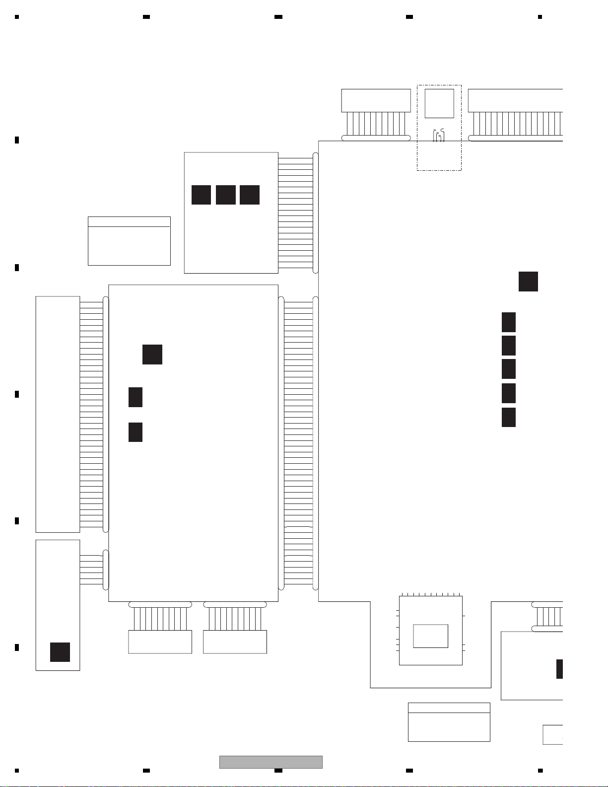
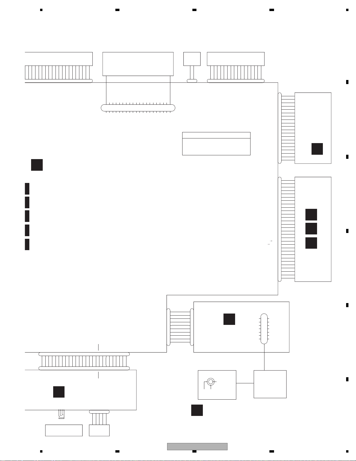
4.1 OVERALL CONNECTION DI AGRAM
24
AVH-P6300BT/XNUC
Page 25
5678
56
7
8
C
D
F
A
B
E
CN101
CKM1516-A
FL-
RL-
FL+
RL+
FR-
RR-
FR+
RR+
P.B.
BGSENS
ACC
B.REM
ILM
MUTE
B.UP
GND
1234567
8
9
10
11
12
141516
13
CN401
CKS5492-A
1
WIRED
2
RCAOUT_L
3
WIREDAD
4
RCAOUT_GND
5
WIRED_GND
6
RCAOUT_R
7
BTMIC_GND
8
VCRIN_L
9
BTMIC_IN
10
VCRIN_LGND
11
BCAM_VGND
12
VCRIN_R
14
VCRIN_RGND
15
VCRIN_VGND
16
VCRAOUT_V
17
VCRIN_V
18
VCRAOUT_VGND
19
NC
20
NC
21
NC
22
NC
23
NC
24
NC
25
NC
26
NC
27
NC
28
NC
29
RCA_FL
30
RCA_FR
31
RCA_FLGND
32
RCA_FRGND
33
RCA_RL
34
RCA_RR
35
RCA_RLGND
36
RCA_RRGND
37
RCA_SWL
38
RCA_SWR
39
RCA_SWLGND
40
RCA_SWRGND
13
BCAM_IN
CN331
CKS4497-A
1
CCR2CCG3CCB
4
CCSYNC
5
GNDSIG
6
DVDVBS
7
GNDDVD
8YS9
ASENB
10
CCAUL
11
CCAUR12GNDAU
14
ONSEI-
15
REAUR
16
REAUL
17
GNDRAU
18
CCREM
19
DSEN20TVON
13
ONSEI+
CKS6025-A
CN751
1
GNDD
2
NC
3
NC
4
GNDD
5
GNDD
6
IECOUT
7
GNDD
8
NC
9
NC
10
GNDD
11
VGND
12
COMPOSIT
13
AGND
14
LOUT
15
AGND
16
ROUT
17
AGND
18
STANBY
19
MS7
SRX
20
S
MS7TX
21
IRGPWR
22
XRESET
23
AMUTE
24
VD5
25
GNDD
26
PGND
27
PGND
28
VD
29
VD
30
VD
CKS3878-A
CN795
BT_MIC1P
SYS+B
BT_MIC1N
BT_RST
BT_SPK1P
BT33
BT_SPK1N
S_BTTX
GNDBT
BT_SRX
1
2
3
4
5
6
7
8
9
10
CKS4822-A
CN1741
1
GND
2
FUN+
CKS5858-A
CN561
REMIN
VCC33NCAUX_L
AUX_AGND
AUX_R
AUX_V
AUX_VGND
USB-
USB+
USB_GND
USB_GND
USB_5V
ILM+B
DSENS
ROT_IN2
ROT_IN1
ILMGND
LED_B
LED_G
LED_R
RESET
GNDKEY
KDT1
KDT0
USB_5V
123456789
10
11121314151617
18
19
20
2122232425
26
CKS3878-A
CN8001
SYS+B
BT_MIC1P
BT_RST
BT_MIC1N
BT_SRX
GNDBT
S-BTTX
BT_SPK1N
BT33
BT_SPK1P
1
2
3
4
5
6
7
8
9
10
CKS6192-A
CN8002
U1IN
1
BT33
2
SPK1P
3
SPK1N
4
VSS
5
NBOOTS
6
U3IN
7
U3OUT
8
NRST_CPU
9
VCC_MIC
10
MIC1N
11
MIC1P
12
VSS
13
U1OUT
14
CKS5858-A
REMIN
VCC33
NC
AUX_L
AUX_AGND
AUX_R
AUX_V
AUX_VGND
USB-
USB+
USB_GND
USB_GND
USB_5V
ILM+B
DSENS
ROT_IN2
ROT_IN1
ILMGND
LED_B
LED_G
LED_R
RESET
KEYGND
KDT1
KDT0
USB_5V
123456789
1011121314
15
1617181920212223242526
YKS5032-A
CN3002
1
USB5V
2
USDM3USDP
4
USGND5USGND
JA3001
CKN1084-A
AUXV
1
AUXL2AUXR3GND
4
CN1402
CKS5554-A
1
NC
2
NC
3
TUN5
4
TUNRST
5
TUN5
6
TUNDATA
7
TUN5
8
TUNCLK
9
TUN_L
10
GNDD
11
GNDTU
12
GNDD
14
GNDD
15
GNDA
16
GNDA
17
GNDRF
18
GNDRF
19
GNDRF
13
TUN_R
20
GNDRF
FAN
POWER SUPPLY
BTMIC_IN
FR/FL
VIDEO_IN
RR/RL
BCAM_IN
WIRED_REMOTE
AUDIO_IN
VIDEO_OUT
SWR/SWL
AUDIO_OUT
USB
AUX INPUT
ANALOG PART
1/5
I/F PART
5/5
POWER SUPPLY PART
3/5
E
CN8601
CKS5749-A
BT MODULE
L
BT PCB
M
BT ANT PCB
C D
DVD MECHA MODULE
CN1901
B
TUNER PCB
F
PANEL PCB
A
MOTHER PCB
MMD PART
4/5
SYSTEM PART
2/5
CN1401
DVD AMP UNIT (SERVICE)
Consists of
MOTHER PCB
TUNER PCB
AVH-P6300BT/XNUC
25
Page 26
1234
1234
C
D
F
A
B
E
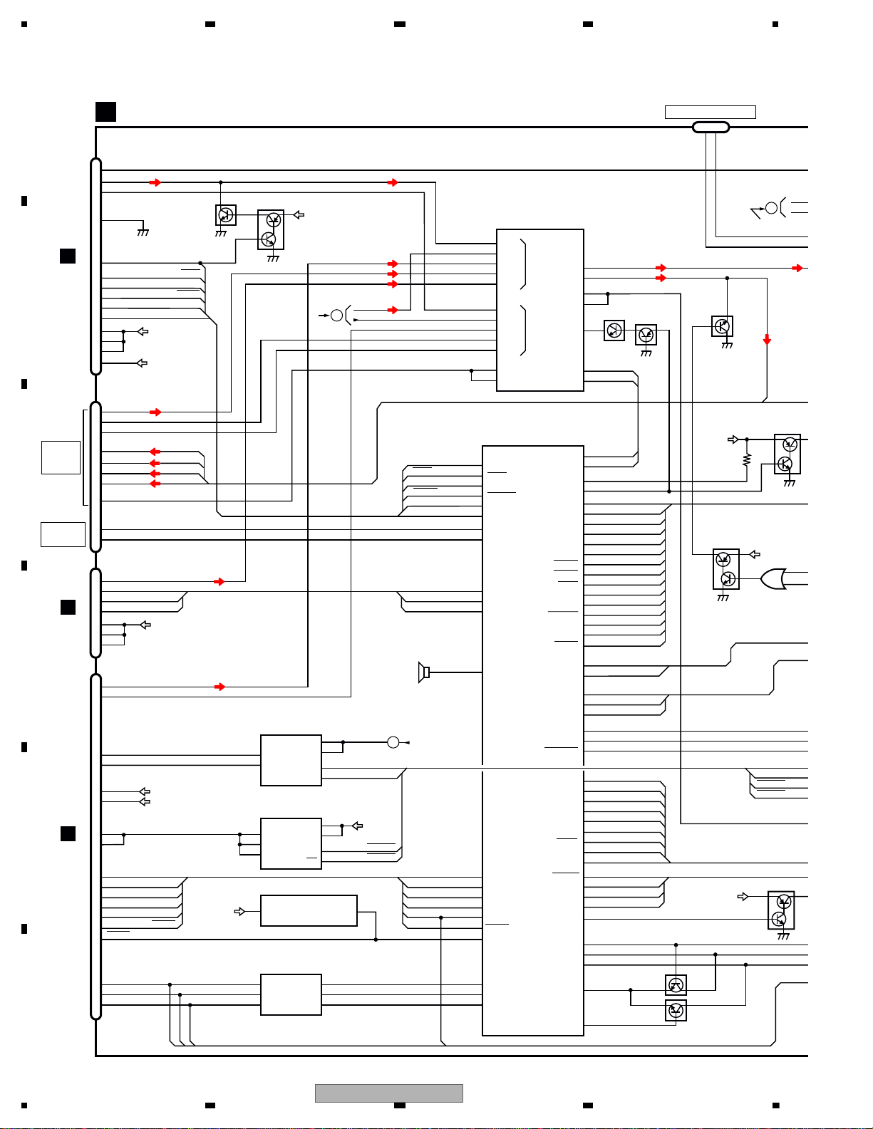
4.2 BLOCK DIAGRAM
14
6
12
4
7
LOUT
IECOUT SPDIF
COMPOSIT
AMUTE
XRESET XRST
IRQPWR IRQPW
STANBY
MS7→SRX
S→MS7TX
STNBY
MS_SRX
S_MSTX
MS_L
MS_L
SOC_L
AUX_L
VCR_L
TUN_L
MS_V
SOC_V
AUX_V
VCR_V
RCA_V
BCAM_IN
MS_V
AUX_L
AUX_V
LIN5
LOUT2
LOUT1
VOUT1
ARET3
SDA
SCL
LIN2
LIN3
LIN4
LIN1
AUDIO_LINVIDEO_IN
VIN5
VIN2
VIN3
VIN4
VIN6
VDOUT2
VDSAG2
AVS DATA
AVS CK
BSENS
ASENS
EVSEL
EVSDA
EVSCK
SACLK
SAIN
AMPMUTE
ISENS
TELMUTEIN
PBSENS
S_to_IP
IP_to_S
ASENBO
REARMUTE
TEMPSEN
DIMMER
MFLPW
BLSYNC
BLERR1
MVIPW
GRST
PNLXV
PNLYV
PNLADX
PNLADY
PNLADCRT
PNLVD
18
24
22
35
VDIN1
34
11
36
67
68
162
105
20
21
103
101
102
104
164
129
148
145
146
36
37
35
128
147
173
81
82
83
167
155
99
97
98
150
151
172
171
170
152
37
6
10
14
2
47
41
43
45
49
29
30
IC602
SYSTEM uCOM
CN751
CN561
30
29
28
24
23
22
21
18
19
20
TUN_L
9
4
6
8
3
5
7
TUN5
TUNRST
TUNDATA
TUNCLK
STANBY
MS_to_S
S_to_MS
58
112
110
111
90
44
43
60
61
EVSTB
EVDATA
AEQAUXSW
MICSENSL
AEQAUXSW
MICSENL
EVCLK
EVSACLK
EVSAOUT
SYSMUTE
TELMUTE
BTRX
75
BT_SRX
BTTX
76
S_BTTX
BTRST
77
BTRST
IP_to_S
S_to_IP
REARMUTE1
AV SELECTOR
IC251
BH7649KS2
AVS DA
AVS CL
AV-LOUT1
Q546
Q545
Q543
SYS+B
BUSL
BUSL
G_to_S
PWGR
MBLPW
S_to_G
29
RGBARI
28
30
GUIDEON
S_to_N
31
N_to_S
VCC33
Q982
Q981
(2/2)
Q981
(1/2)
7
23
13
14
24
1
15
16
18
ROT_IN1
ROT_IN2
ROTIN1
ROTIN2
KDT0
KDT1
25
DSENS DSENS
ROTIN1
ROTIN2
REMIN
KDT0
KDT1
RESET
62
63
175
174
DSENS
176
16
1
WIRED
WIRED
160
3
WIREDAD
WIREDAD
161
REMIN
RESET
19
20
21
26
2
ILMDT
ILMCK
ILMLD
LED_R
LED_G
LED_B
ILMDT
ILMCK
ILMLD
54
55
53
AO1
AO2
AO3
DI
CLK
CSB
12
11
10
1
1
2
5
ILMB
VCC33
10
9
USB+
USB-
USB_D-
USB_D+
VDCNT5
B2
A1
B1
A2
1OE
2OE
11
2
13
3
1
12
DD5
USB_5V
OUT1
OUT2
OUT3
EN
OC
4
5
8
6
USBCNT
USBFLG
USB5 REG.
IC521
BD82001FVJ
RGB DRIVER
IC511
BH2227AFV
USB BUFFER
IC522
TC7MBL6126SFK
POWER ON RESET
IC601
S-80827CNMC-B8M
SOCSTBY
51
52
91
CN401
8
17
13
2
16
37
29
33
VCRIN_L
VCRIN_V
BCAMIN
RCAOUT_L
RCA_SWL
RCA_FL
RCA_RL
VCRAOUT_V
VCR_V
VCR_L
BCAM_IN
RCA_L
RCA_V
SYS+B
VD8
VD5
XRST
STNBY
MS_SRX
S_MSTX
AMUTE
IRQPW
AMUTE
XRST
IRQPW
Q752
Q751
TUNRST
TUNCLK
34
BEEP
TUNDATA
BGSENS
TEMPSEN1
S_to_SO
SO_to_S
19
4
14
6
6
14
4
USB_D-
USB_D+
USBCNT
USBFLG
CN1401
B
CN3001
F
MOTHER PCB(1/2)
A
SOC_L
SOC_V
RCA_L
AMPPW
131
AMPPW
CN2021
ASENBO
AVS DA
AVS CL
(1/2)
VDD33
2
(1/2)
CN1402
IN1
IN2
3
2
7
BZ601
Q401
BUP-1
REAR
Q164
OFFM
LEDR1
LEDG1
LEDB1
KDT1
CN331
14
13
ONSEI-
ONSEI+
(1/2)
C
BUZZER
AMUTE
CN1901
C
A
TO 2/2
B
RCA_L
TO 2/2
WIRED
REMOTE
AUDIO
VIDEO
IN/OUT
DGND
4
NAVI INTERFACE
VD
ILM+B
AUTO
MIC S
REAR MUTE
UC:PE5762A8
RD,RI:PE5763A8
26
AVH-P6300BT/XNUC
Page 27
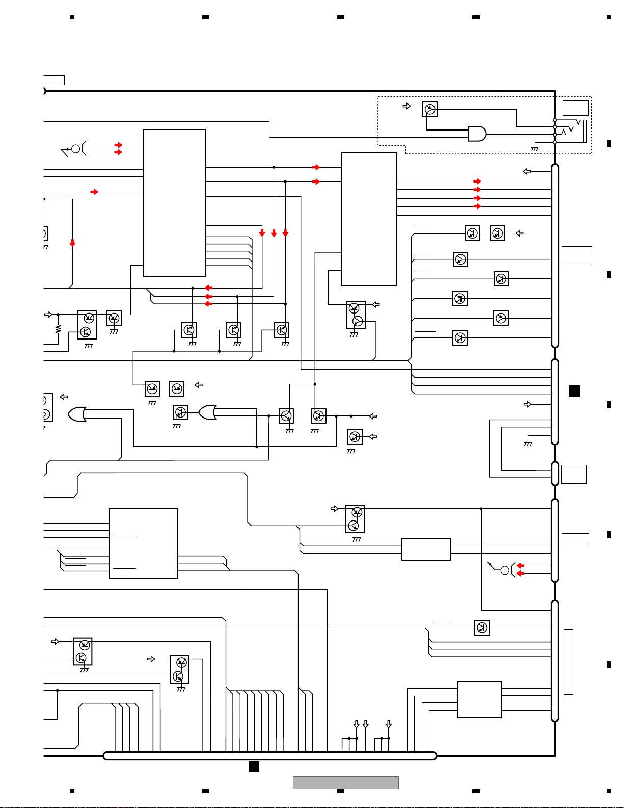
5678
56
7
8
C
D
F
A
B
E
Q155
CN101
CN401
JA301
CN331
IN1
OUT1(+)
OUT1(-)
OUT3(+)
OUT3(-)
H-SW/VOS-DET
IN3
MUTE
STBY
AMP
IC151
PA2030A
30
32
31
27
28
EVCLK
EVDATA
EVSAOUT
EVSTB
59
RCA_SWL
60
RCA_RL
61
9
7
17
19
25
15
11
22
4
RCA_FL
FL+
FL-
RL+
RL-
EVSACLK
Q543
Q541
Q441
Q162
Q161
3
1
4
2
12
11
13
14
9
10
8
7
11
1
5
9
7
Front_L
Rear_L
Pre_SWL
STB
DATA
CLK
SACLK
SA_TEST
IN2L
IN3L
MIC-In
IN4L+
IN4L-
E-VOL
IC201
PML020A
Q163
BUP_1
SYSMUTE
AMPPW
12
11
IN5L
14
IN5G
15
BUSL-
BUSL+
18
9
8
BT_TEL
STS+B
BUP_1
15
ACC
ILM
MUTE
BGSENS
BT_MICIN
BTMIC_GND
ADVY
ADVX
ASENBO
BUS+
BUS-
BUSL+
9
ASENB
BUSL-
B.REM
BUP_1
ASENBO
IP_to_S
S_to_IP
IC301
HA12241FP
ROUT
BUS+
DIN1
BUS-
VCC33
55
53
54
Q153
Q153
Q122
Q122
Q123
Q123
Q125
Q121
Q124
Q301
ASENS
BSENS
BGSENS
TELMUTE
PBSENS
ISENS
Q982
Q983
2
6
5
1
SOCSTBY
P.B .
(1/2)
(2/2)
OFFMUTE
S_to_SO
SO_to_S
191
48
VBUS_OUT
USBLIMIT
146
67
65
144
49
USB_D-
USB_D+
USBCNT
USBFLG
BT_MIC1P
BT_MIC1N
1
3
BT_SPK1P
BT_RST
BT_TEL
BT_SRX
S_BTTX
BTRST
5
10
8
4
6
CN795
27
678
41
42
383736
48
40
39
22
49
50
21
43
2
1
252423
13
20
543
PWRBL
ILMB
PWRVI
PLXV
PLYV
G_to_S
MONPW
S_to_G
GRST
TEMP
DIMPLS
MBLPW
BLCLK
BLERR1
DGCLK
G_to_D
D_to_G
DGCLK
G_to_D
D_to_G
CN5002
K
IC801
(1/2)
MMD
MN2DS0018MA
MOVBS
171815
16
ANAB
ANAG
ANAR
CSYNC
BUP_1
(2/2)
CN2021
Q442
(2/2)
Q442
(1/2)
RCAMUTE
OFFMUTE
(2/2)
(2/2)
(1/2)
(1/2)
Q481
VCC5
IC481
TC7SET08FUS1
1
2
4
S/PDIF
OUT
USB_D-
USB_D+
SYS+B
BUP_1
Q154
BUP-1
REARMUTE1
OFFMUTE
IP BUS
LEDR1
LEDG1
LEDB1
31
KDT1
1
2
CCR
CCG
IC351
NJM2138V
RGB VIDEO ISOLATOR
810
12
3
CCB
3
4
CCSYNC
5
14
1
7
20
TVON
21
GION
24
SYS_TO_NAVI
25
NAVI_TO_SYS
S_to_N
GUIDEON
N_to_S
Q601
(2/2)
RGBARI
RCA_RL
RCA_FL
RCA_SWL
BT33
NAVI INTERFACE
POWER
JA481
3
2
4
1
C
C
CN8001
L
PWGR
BLSYNC
DIMMER
TEMPSEN1
RCA_L
IP-BUS DRIVER
SUPPLY
VCC_MIC
2
BTMIC
IN
AUTO EQ
MIC SENS
MUTE
ILR
ILG
ILB
KEY1
RCA MUTE
PA_ RL
PA_FL
AMP
MUTE
OFF MUTE
GtoS
StoG
GRST
GtoD
DtoG
B.UP
BGSENS
PBSENS
TELMUTE
ISENS
ASENS
BSENS
C_OUT
D_OUT
A_OUT
B_OUT
C_+IN
D_+IN
A_+IN
B_+IN
RD,RI only
AVH-P6300BT/XNUC
27
Page 28
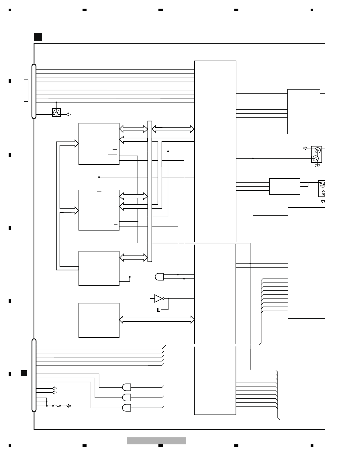
1234
1234
C
D
F
A
B
E
ADOUT
LRCK
XWR1
XRD
A16-A19A16-A19
A16-A19
D0-D15D0-D15
D0-D15
D0-D15
DATA
LRCK
VOUTL
BCK
SCK
MC
MD
ML
SRCK
DACCK
SDODAC
SCKDAC
LTDAC
NEXWE
XCSF2
XCSF1
USB_CLK
X802
SOAMUTE
CPSDL
CPSCK
CPRST
151
COMPOSITE
138
2
IC801
MN2DS0018MA
MMD
DAC
IC941
PCM1753DBQ
150 3
7
149 1
148 16
63 13
64 14
15
62
71
NRST
70
46
47
61
13
12
4
2
5
31
SYS+B
FLASH 16Mbit
IC921
PEH305A8
FLASH 16Mbit
IC922
PEH304A8
LATCH
IC923
TC74LCX16373FT
IC924
TC7SZ08FU
SDRAM
IC901
IS42S16400F-7TL
iPod CP IC
IC951
341S2162
IC802
TC7SZU04FU
11
11
48
25
1
2
213
NEXOE
214
59
50
D_TRCDATA0
77
D_TRCDATA1
78
D_TRCDATA2
79
D_TRCDATA3
80
D_SCLOCK
72
D_SDATA
73
D_TRCCLK
76
D_TRCST
81
D_EXTRG0
74
4
1LE
2LE
A0-A15
A0-A15
A0-A15
42
I2C_SDA
I2C_SCL
VCC
MODE1
nRESET
Q95
SYSTEM uCOM
UC:PE5762A8
SOCRESET
SOCRES1
115
IRQPW
58
SOCIRQ
116
12
CE
26
28
28
26
12
DDCCL
VD
CLCNT
CLCNT
VD
SYSP
HIOUTCL
SOCAMUTE
117
Q941
MOTHER PCB(2/2)
A
(2/2)
IC602
(2/2)
WE
RESET
WE
RESET
BUP_1
VCC5
VCC33
SOCRES1
P2001
TC74VHCT08AFKS1
2
3
12
11
9
8
169
23
27
139
25
24
138
137
26
7
8
DAT0
DAT1
DAT2
CMD
CLK
WP
CD
CN961
4
9
CD/DAT3
1
2
5
14
12
VCC33
Q961
SD CARD
VDD
2
3
LIFTPUI
MTRS
MTRPW
ANGL0SW DEG0SW
MTR2
MTR1
MTRSEL
ANGLE
CN2001
10
11
18
19
20
4
8
5
LFTSW
9
6
7
1
IC2001
MTR2
MTR1
MTRSEL
LFTPULS
DEG0SW
LFTPULS
MTRS
MTRPW
DEG0SW
MTR2
MTR1
MTRSEL
ANGLE
LFTSW
2
1
8
7
4
3
215
216
SDDAT0
SDDAT1
SDDAT2
SDDAT3
SDCMD
SDCLK
SDWP
SDCD
OE
OE
CE
CN101
H
LFTPULS
SENPW
VDD
BUP
D_TRCD0
D_TRCD1
D_TRCD2
D_TRCD3
RD,RI:PE5763A8
28
AVH-P6300BT/XNUC
Page 29
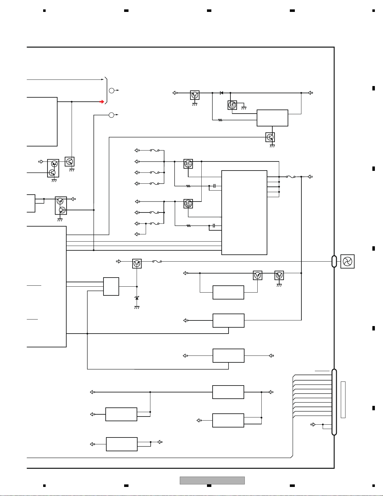
5678
56
7
8
C
D
F
A
B
E
VOUTL
SOC_L
VDCNT5
SOC_V
DAC
IC941
7
2
5
SYS+B
Q942
VCC
VCC33
Q951
2
CN1741
CN801
BUP_1
Q1002
Q1001
VDD33
SYS+B
BUP_1
SYS+B
DD8
Q1621
EV12
P1501
1
2
3
6
4
7
22
19
18
23
24
13
8
9
COMP1
HSD1
FB1
P1711
P1731
P1611
P1741
P1651
Q1501
Q1502
Q1741
Q1742
Q1743
SYNC
EN1
EN2
HSD2
COMP2
FB2
DC-DC CONVERTER
FAN DRIVE
IC1501
AN33012UA
IC1001
S-812C33AUA-C2N
DD5
VD5
P1721
VCC5
PWRVI
DD8
VD8
ILMB
PWRBL
OUT
VCC
EaIn
OSC
Q1623
Q1622
5
3
1
3
5
1
7
EV12 REG.
IC1621
TK11840L
SYS+B
IC1201
BD00D0AWHFP
AVCC5 REG.
IC1221
S-1200B50-M5
AVCC5
VCC5
DD8
2
1
4
TUN5 REG.
IC1101
NJM2846DL3-05
BT33 REG.
IC1781
S-1132B33-U5
VCC33 REG.
IC1771
NJM2855DL1-33
VCC12 REG.
IC1761
PQ012GN01Z
TUN5
VCC12
5
1
4
1
3
1
3
2
VCC33
BT33
SYSTEM uCOM
UC:PE5762A8
92
114
113
DDCCLK
VD8
142
CLCNT2
141
CLCNT1
VD5
130
SYSPW
HIOUTCLK
66
ON/OFF
VCC
VCC_S1
RS2
VCC_S2
RS1
3
2
4
2
1
CTL
SW
CONT
VB
Q941
IC602
(2/2)
VOUT
VIN
Vout
Vin
VO
VCC
VOUT
VIN
Vout
Vin
VOUT
VIN
VOUT
VIN
Q1744
14
13
D_TRCD0
D_TRCD1
D_TRCD2
D_TRCD3
D_SDATA
D_TRCCLK
D_TRCST
SOCRES1
D_EXTRG0
3
2
1
12
11
8
D_SCLOCK
9
6
5
4
TO DEBUGGER
VCC33
FAN
A
TO 1/2
B
TO 1/2
VDD33 REG.
SYSPW
RD,RI:PE5763A8
AVH-P6300BT/XNUC
29
Page 30
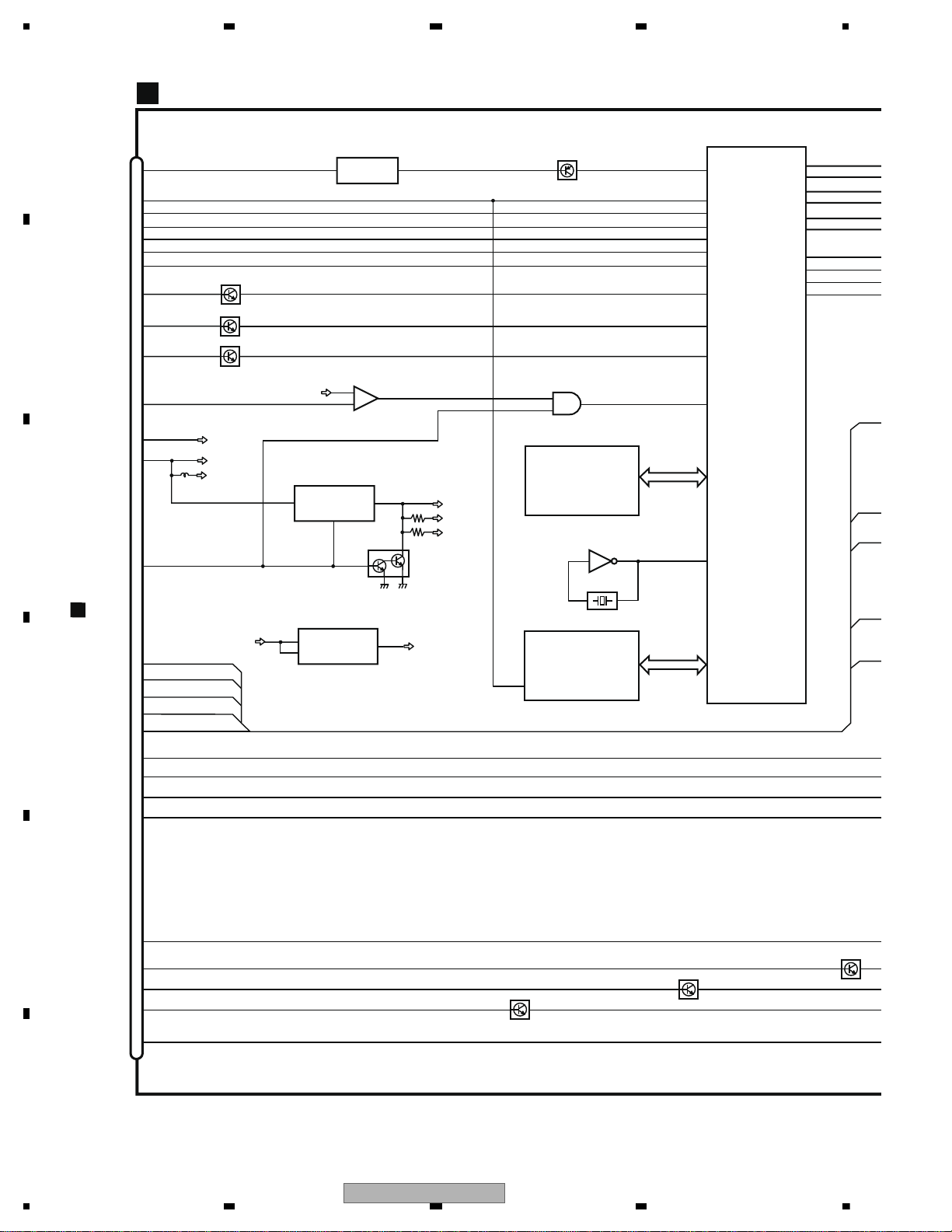
1234
1234
C
D
F
A
B
E
CN5002
X5502
9.597MHz
LCDOR [0-5]
LCDOG [0-5]
LCDOB [0-5]
LCDOC0
52
93
LCDOC1
92
GPIO9
87
LCDOCLK
88
BLER
MBLP
AV0INB
GERDA-L
IC5502
MN103SH13
4
2
MOVBS
133
72
73
IC5503
TC7SHU04FUS1
LCDICLK
64M FLASH
IC5401
MONITOR PCB
38
PWRBL
12
10
9
PLXV
CN2021
11
I
45
43
I
3
1
PWRVI
DIMP
TEMP
135
Q5808
IC5501
S-93C66BD0I-I8
31
30
29
GRST
GtoS
StoG
NRST
GPIO11
GPIO10
PLYV
ADVX
ADVY
Q5201
8
MONPW
Vin
Vo
4
IC5201
PQ1LA125MSPQ
GD12V
Vc
PNLVI
VIN VOUT
6
IC5202
S-1172B34-E6
PNLVI
ON/OFF
3.3V→1.2V
5V→3.3V
1
5
3
3
PW
BLCL
47
48
49
46
BLERR1
MBLPW
TEMP
50
K
A
AV0INA
AV1IN
AV2IN
DV0VSY
34
36
33
ANAR
CSYNC
ANAG
ANAB
35
Q5807
Q5806
Q5805
-
+
4
1
3
RGBVI
IC5311
TC75S57FU
50
57
63
43
UC:PEH302B8
RD:PEH303B8
RI:PEH301B8
EEPROM
RESET
12
DIMPLS
TEMP1
BLCLK
Vin Vout
4
IC5301
NJM2505AF
C.VIDEO
1
77
75
74
28
27
26
DGCLK
GtoD
DtoG
GPIO2
GPIO1
GPIO0
1
TC7SET08FUS1
IC5312
2
4
RGBVI
GD33V
V33A
Q5801
Q5801
Q5802
24
14
15
ILR
13
ILMB
ILG
ILB
20
KEY1
(1/2)
(2/2)
PWRVI
30
AVH-P6300BT/XNUC
Page 31
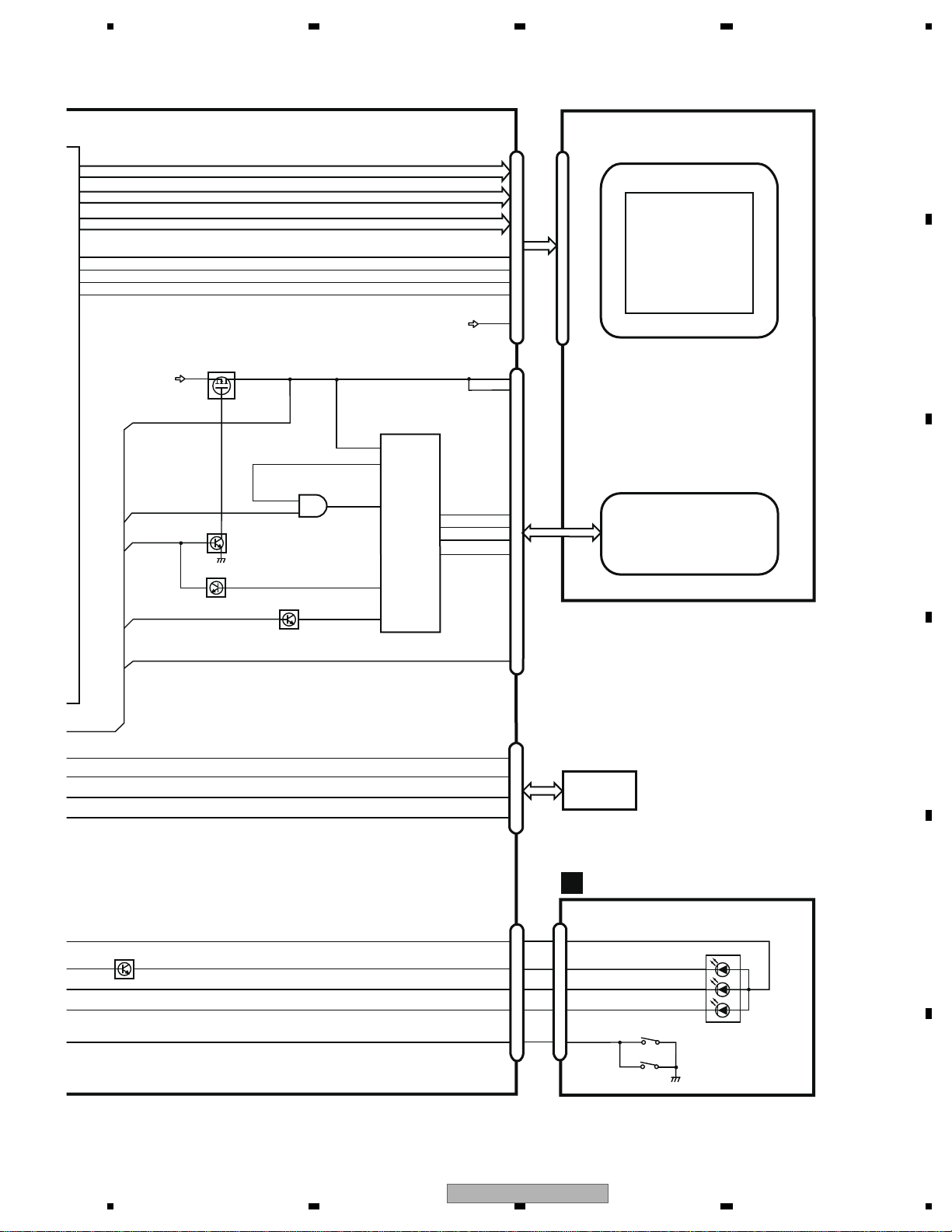
5678
56
7
8
C
D
F
A
B
E
LR[0-5]
LG[0-5]
LB[0-5]
|
18
23
|
25
30
|
32
37
13
14
39
16
CN5601
CN5701
-5]
-5]
-5]
VSYNC93
HSYNC92
SHUT87
LK
DCLK88
BLERR1
MBLPW
LCD
LCD
LCD BACKLIGHT
VCC
BLP
CN5101
PNLVI
DIMPLS
TEMP1
SW
CLKI
LED1
IC5701
TK61222CQ6
17
15
8
3
1
19
FAULT
6
1
9
BLP
7
4
Q5703
|
5
8
LCD BACKLIGHT DRIVER
18
LED3
LED2
LED4
LED1
LED3
LED2
LED4
3
2
PWRBL
Q5701
DIM
10
Q5705
BLCLK
TEMP1
TOUCH
PLXV
PLYV
.
5
4
.
3
2
.
7
6
.
9
8
ADVX
ADVY
PANEL
4
2
TC7SET08FUS1
IC5702
Q5702
1
VREG
6
KEYBOARD PCB
G
CN3500
KEY1
S3500
D3500
LEDB1
ILMB
LEDR1
1
5
LEDG1
2
3
4
S3501
CN5802
6
2
5
4
3
Q5801
LEDR1
ILMB
LEDG1
LEDB1
KEY1
(1/2)
AVH-P6300BT/XNUC
31
Page 32
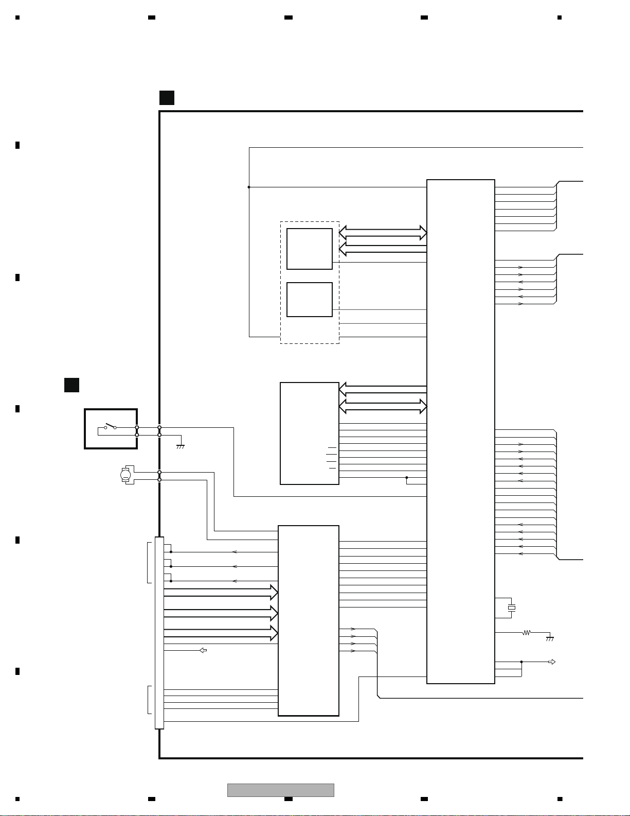
1234
1234
C
D
F
A
B
E
DVD CORE UNIT (MS7)
C
MA0-11
MDQ0-15
D0-15
MN2DS0018MAUB
IC1501
VIDEO+AUDIO
SRCK
LRCK
ADOUT
SDODAC
LTDAC
SCKDAC
DACCK
149
150
151
46
45
47
148
F+H_G+H
E+G_E+F
VIN4RF
VIN2RF
VIN1RF
VIN3RF
VIN8
DVDMPD
TEMP
RFINP
CDMPD
LPCO2
LPCO1
111
112
99
98
97
100
116
105
A
A
C
C
D
D
B
B
FE1
FE2
RF
122
96
103
106
104
COMPOSITE
152
138
STANDBY
191
57
56
58
55
CMDCOMN
STSCOMN
IRQPWR
AMUTE
NRES
OSCO
OSCI
X1501
27 MHz
156
155
VREF
A0-19
HWP (HW+), HWM (HW-)
HVP (HV+), HVM (HV-)
HUP (HU+), HUM (HU-)
XRDNRES 28 214
NEXOE
NEXWE
70
NRES
IECOUT59
XCFS1
213
31
NEXCE
26
12
/CE
/CE
/OE
/RESET
K4S641632N-LC75
SDRAM
IC1480
19
38
CS
CLK
XWE16 181
NWE
XCAS
DQM0
DQM1
17 188
NCAS
XRAS18 189
NRAS
XCSM 190
NCSM
20 193
BA0
21 197
BA1
BA0
BA1
15 179
DQM0
39
19
20
27
39
53
37
33
35
12
10
180
DQM1
LDQM
UDQM
MCK
VHALF
TD
FD
MD
CONT1
CONT2
DRV2
DRV3
FOP
183
MCK
185
121
MCKI
VDSENS
CAS
RAS
WE
BD8217EFV
IC1201
MOTOR DRIVER
SPINDLE MOTOR
CTL1
CTL2
FG
FCO+
FIN
VC
TIN
LDIN
SPIN
HALL_VC
V_OUT
41
LDO+
42
LDO-
CN1201
5
6
HALL_BIAS-
SWITCH HOME
HBM
HALL_BIAS+
COIL_V
127
126
66
71
54
53
FG
CONT2
CONT1
HOME
62
MD
LDIN
FD
TD
120
VIN1
109
VREFH
119
VIN2
118
VIN4
VIN3
117
114
VIN6
113
VIN5
31
SL1IN
65
STEPPER2
29
SL2IN
64
STEPPER1
43
FOM
FCO-
44
TOP
TKO-
46
TOM
TKO+
45
63
110
VHALF
67
CLAMP
VIN7
115
FLASH 16M
IC1401
CWW2238
XCFS2
XCFS1
26
11 XWR1
/WE
IC1402
CWW2239
VCC5
LOM
LOP
M
LOADING
MOTOR
CLAMP
13
W_OUT
7
8
COIL_W
11
U_OUT
CLAMP1
CLAMP2
9
10
11
SLO1+4
SLO1-2
SLO2+3
SLO2-
15
16
17
18
1
18
20
COIL_U
S1206
COMPOUND UNIT(B)
E
STEPPING MOTOR
32
AVH-P6300BT/XNUC
Page 33
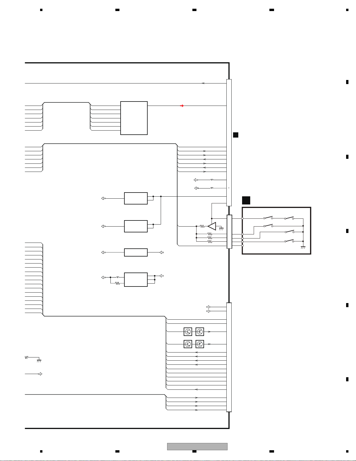
5678
56
7
8
C
D
F
A
B
E
AVCC5
VOUTL
7
BCK
LRCK
DATA
MD
1
3
2
13
PCM1753DBQ
IC1801
AUDIO 2CH ANALOG OUT
LOUT
ML
MC
SCK
15
14
16
SRCK
ADOUT
SDODAC
LRCK
LTDAC
SCKDAC
DACCK
Q1104Q1102
VREF
VCC5
CN1101
78LD(CD)
F+H_G+H
E+G_E+F
F+H/G+H
E+G/E+F
LPCO2
25
19
20
21
11
12
9
15
14
10
5
17
24
22
8
Q1103Q1101
65LD(DVD)
VCC
Vref
LPCO1
A
A
C
C
D
D
B
B
FE1
FE2
RF
5
1
3
VIN
VOUT
ON/OFF
S-1200B50-M5
IC1900
AVCC5 REG.
VCC5
VD8
5
4
3
VIN
VOUT
ON/OFF
S-1133B50-U5
IC1901
VCC5 REG.
A
7
B
C
D
FE1
FE2
78MDCDMPD
65MDDVDMPD
TEMP TH
RF
1
2
4
3
F-
F+
FOM
FOP
TOP
TOM
T+
T-
VD8
XRESETNRES
501
MHz
ANALOG LOUT
CN1901
9
3
17
25
11
10
13
8
7
12
1
2
19
VREF
COMPOSITCOMPOSITE
STANBYSTANDBY
HSTCMDCMDCOMN
SLVSTSSTSCOMN
IRQPWR
AMUTE
IECOUT
13
VCC33 VDD5
NJM2885DL1-33
IC1004
3.3V REG.
INOUT
2
8
VDD5
VCC12
IC1005
1.2V REG.
R1232D121B
VIN
VDD
CE
LX
5
VOUT
VDD5
VD5
PU (DP8.6)
3
4
CN751
A
4DSCSNS 2
1
WAKE U P
Disc
8cm
8cm
12cm
PhotoPHOTOSNS
3
2
1
4
5
4
S1203
S1204
DISC SENS
3
S1202
8cm
S1201
2
12cm
5
S1205
8cm
6
CN1301
21
COMPOUND UNIT(A)
D
AVH-P6300BT/XNUC
33
Page 34
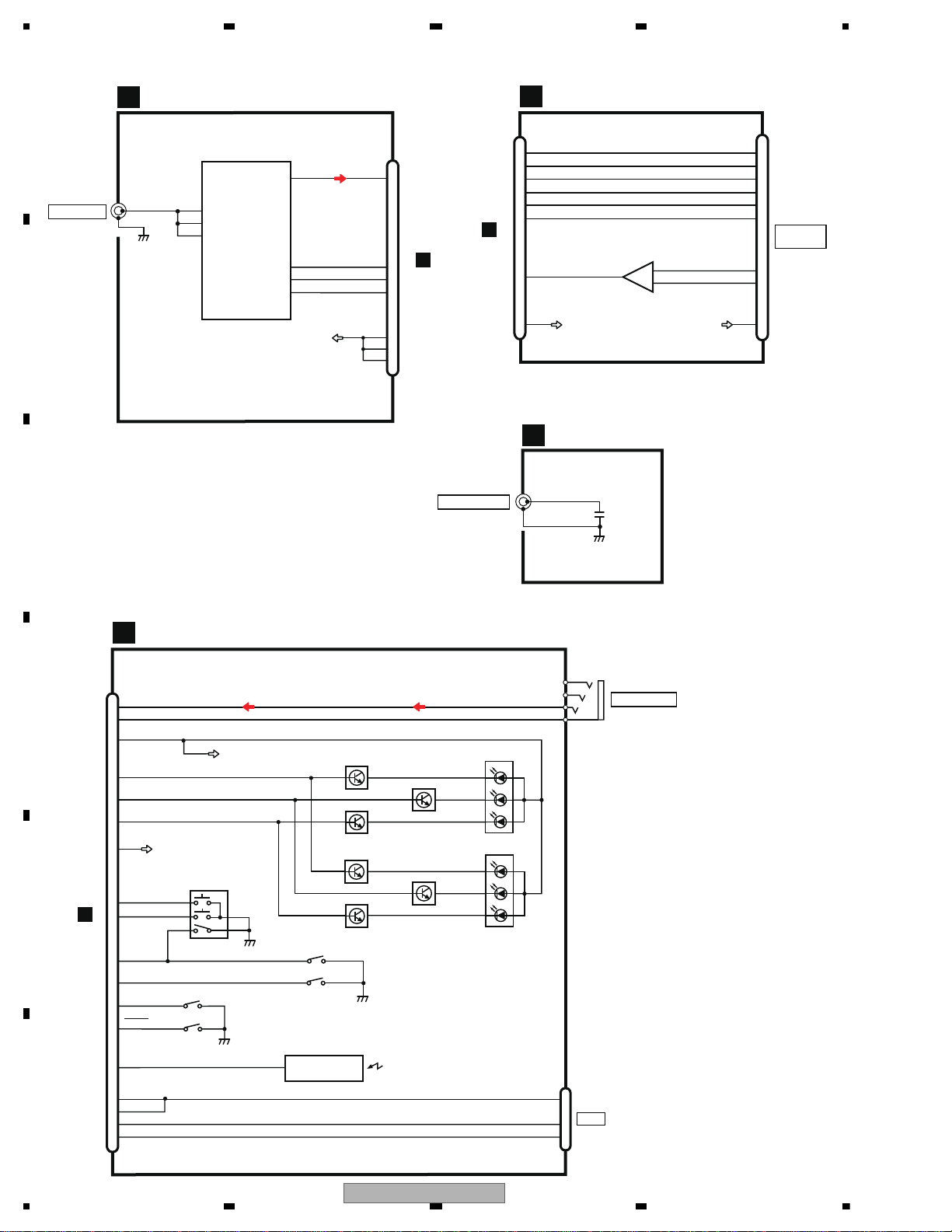
1234
1234
C
D
F
A
B
E
TUNER PCB
B
RF FRONT END IC
IC1401
TDA7706
I2CSDA
I2CSCL
57
DACOUTL
FMMIXIN1
JA1401
5
RSTN
ANTENNA
TUN_L
34
14
33
16
31
18
16
PINDIN
18
LNAIN
1
2,3
TUNDATA
TUNCLK
TUNRST
A
CN1402
15
13
17
TUN5
BT
A
CN795
6
8
7
BT PCB
L
CN8001
BT_SPK1P
BT_SRX
BT_RST
BT_MIC1N
CN8002
U1OUT
NRST_CPU
MIC1N
3
1
S-BTTX
11
CN1401
3
2
SPK1N
3
4
SPK1P
IC8001
NJM4558V
U1IN
10
9
VCC_MIC
BT_MIC1P
VCC_MIC
MIC1P
11
9
1
14
12
10
5
BT33
2
BT33
BT ANT PCB
M
CN8601
1
2,3
BT MODULE
+
-
PANEL PCB
AUX INPUT
USB
AUXL
GND
AUXV
2
4
3
1
KDT0
KDT1
16
15
23
24
2
1
4
3
5
AUX_L
AUX_V
ROT_IN2
ROT_IN1
7
4
AUXR
VOLUME/MUTE
USB_5V
USB-
USB+
REMIN
VCC33
14
13
9
10
1
2
18
1
2
3
USB5V
USDM
USDP
GP1UXC14RK
SENSOR
1
REMOTE CONTROL
JA3001
CN3001
S3003
CN3002
IC3001
F
S3002
RESET
25
S3001
DSENS
D3009
LED_R
ILM+B
LED_B
19
26
LED_G
20
21
Q3001
Q3001
Q3002
(2/2)
(1/2)
D3010
Q3003
Q3003
Q3004
(2/2)
(1/2)
A
CN561
USB_5V
MODULE
ILMB
S3004,S3005
S3006,S3007,S3008
34
AVH-P6300BT/XNUC
Page 35
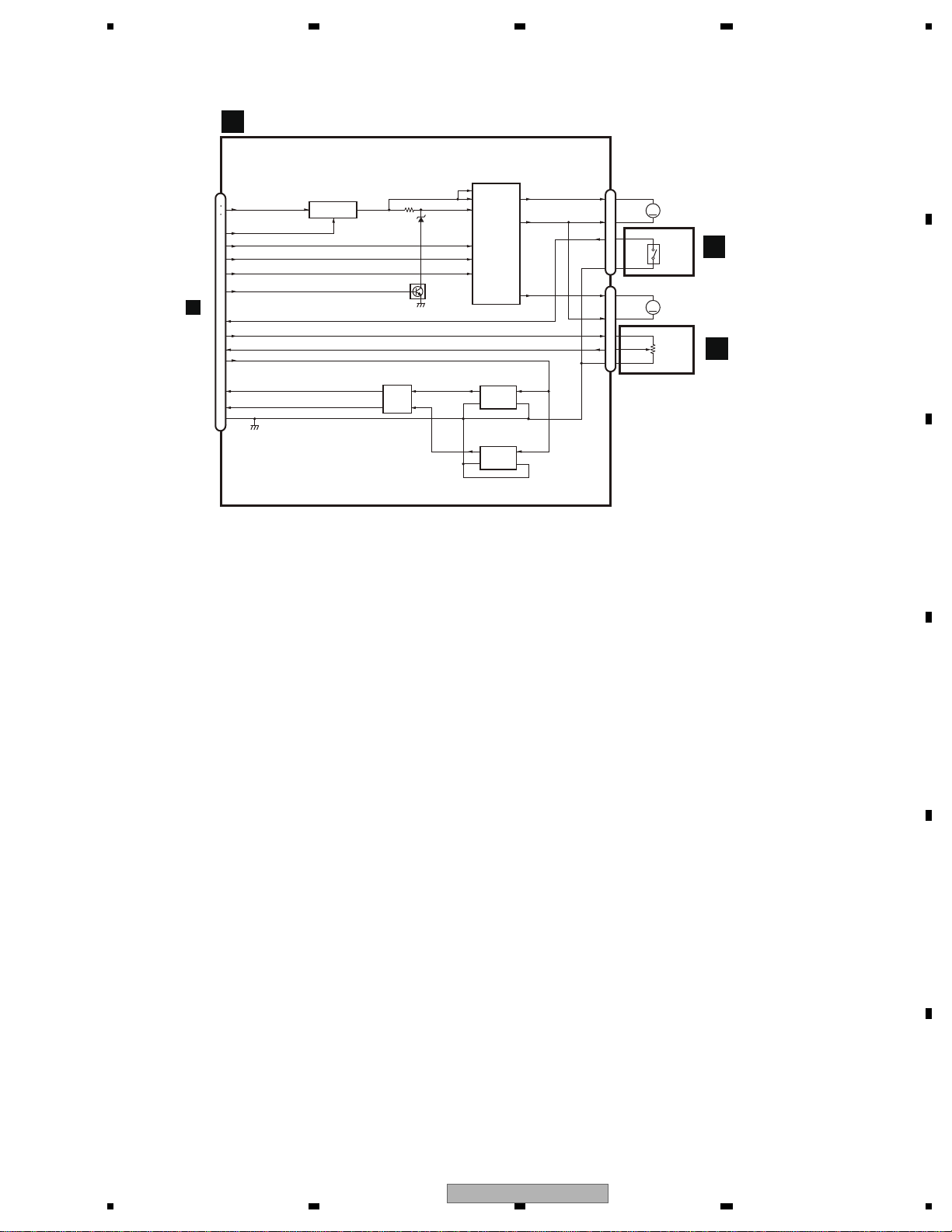
5678
56
7
8
C
D
F
A
B
E
MAIN PCB UNIT
A
CN2001
A
H
1
2
3
17
14
15
16
18
13
10
20
11
19
12
8
CN101
BUP
MTRPW
MTRSET
(ANG)MTR1
(POS)MTR2
MTRS
ANGLEOSW
3.3V
ANGLEIN
5V
LIFTPUL
LIFTSW
DGND
5V REGULATOR
2
BA00CC0WFP
IC101
4
1
Q101
WAVE SHAPE
IC104
TC7W14FU
1
7
1Y
1A
3
5
2Y
2A
MOTOR DRIVE
IC102
BA6247FP
9
VCC1
16
VCC2
14
VR
8
IN3
5
IN1
6
IN2
OUT3
OUT1
OUT2
1
18
22
SLIDE PULSE OUTPUT
IC105
GP2L24B
3
2
1
C
A
4
K
E
IC103
GP2L24B
1
3
C
A
2
4
K
E
LIFT SW (EJECT:L)
CN102
1
2
3
4
CN103
1
2
3
4
5
ANG_V
ANG_IN
ANG_G
M102
SLIDE
M
MOTOR
S
S101
ANGLE
SWITCH
G
M103
ANGLE
M
MOTER
VR101
ANGLE
SENSER
SWITCH PCB UNIT
I
VOLUME PCB UNIT
J
AVH-P6300BT/XNUC
35
Page 36
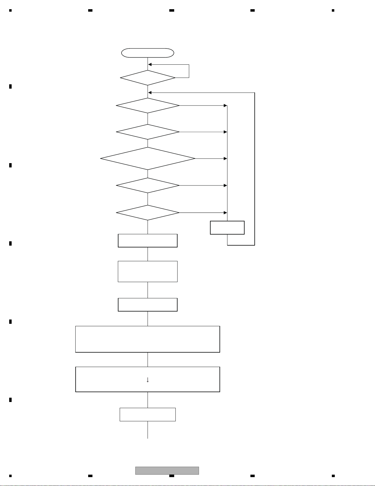
1234
1234
C
D
F
A
B
E
5. DIAGNOSIS
RESET
VDD = 3.3 V?
/BSENS = L?
/ASENS = L?
ASENBO <- H
VD5 <- H
VD8 <- H
DDCCLK <- Clock Out
Starts
Communication
with Display microcomputor
Source Keys oper ative
Source ON
SYSPW <- H
Standby
/BSENS : Pin20
/ASENS : Pin21
ASENBO : Pin35
DDCCLK : Pin92
VD5 : Pin113
VD8 : Pin114
SYSPW : Pin130
Y
Y
Y
/STANBY = H?
/STANBY : Pin90
Y
(Frequency of 370 kHz)
/SOCSTBY = H?
/SOCSTBY : Pin91
Y
VDD : Pin11
/DSENS = (1.15 V to 1.95 V)?
/DSENS : Pin176
Y
5.1 OPERATIONAL FLOWCHART
36
AVH-P6300BT/XNUC
Page 37
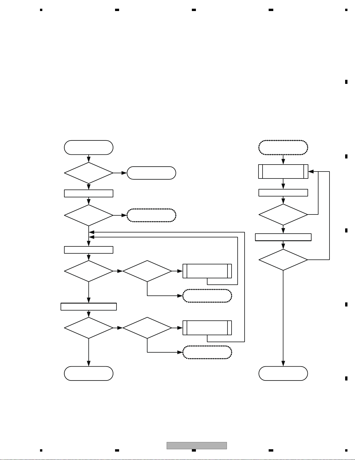
5678
56
7
8
C
D
F
A
B
E
START
Check LD current
Within prescribed
value?
Check RF level
Within prescribed
value?
No problem found
in pickup
Lens cleaning
completed?
Clean lens
Adjust skew
Check RF level
Within prescribed
value?
Check LD current
Check RF level
Check RF level
Yes
No
Yes
No
Check 1
Check 2
Check 3
Check measured value of error ratio
End
Light up pickup
Diagnose in a
normal way.
No
Check error ratio
Within prescribed
value?
Lens cleaning
completed?
Clean lens
Check measured value of error ratio
Check error ratio
Within prescribed
value?
Replace pickup
To “Replace pickup”
To “Replace pickup”
To “Replace pickup”
Check 2
Check 3
Yes
Yes
Yes Yes
Yes
Yes
No
No No
No No
* Make sure to avoid any unwiped
spots or actuator breakage.
* Make sure to avoid any unwiped
spots or actuator breakage.
Judgement of pickup conditions
• Disc used:
CD-DA : TCD-782
DVD-Video : GGV1025
* Handle or store discs with care as scratched or dirty discs cannot provide accurate judgement.
• How to diagnose
* For the details of checks 1 to 3, see the next page.
See also the mecha test mode described in the service manual.
5.2 INSPECTION METHOD OF PICKUP UNIT
AVH-P6300BT/XNUC
37
Page 38
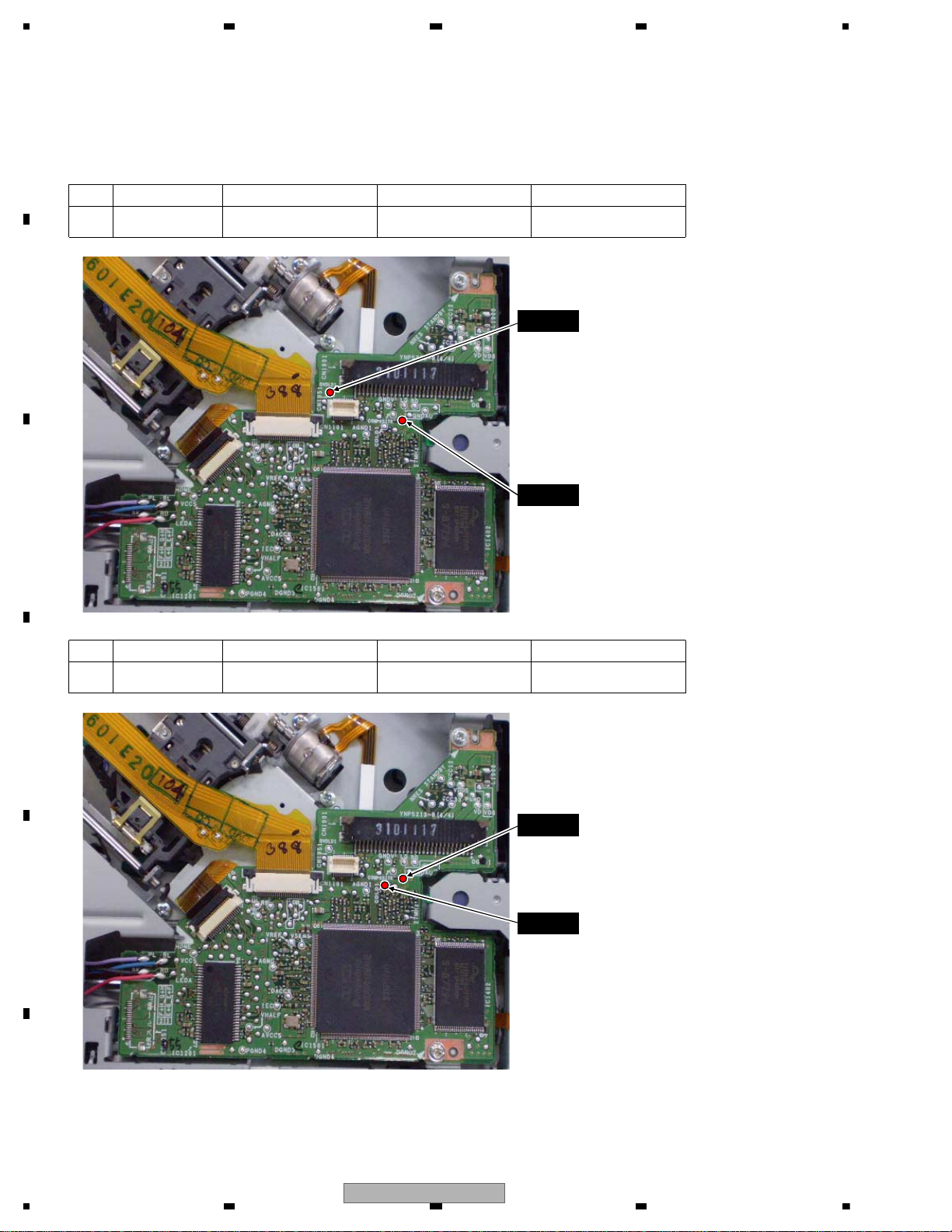
1234
1234
C
D
F
A
B
E
DVDLD1
VCC5_3
VCC5_3
CDLD1
Check 1: Check LD current
<Check>
Check the voltage value between terminals in the focus closed status in the test mode.
Mind breakage of a laser diode caused by static electricity.
Remarks: LD current value (ref.)
GGV1025 DVDLD1-VCC5_3 60~390(mV) 10~65(mA)
NO.
1
Disc used Spot to check Rated value
Remarks: LD current value (ref.)
TCD-782 CDLD1-VCC5_3 60~360(mV) 10~60(mA)
NO.
2
Disc used Spot to check Rated value
38
AVH-P6300BT/XNUC
Page 39
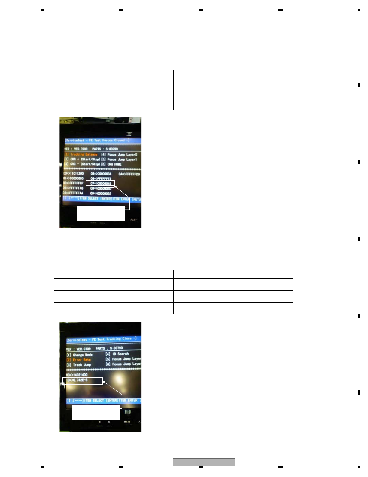
5678
56
7
8
C
D
F
A
B
E
ASMAX value:
00000045 in this case
Error ratio:
0.742E-5 in this case
Check 2: Check RF level
<Check>
Check the “ASMAX value” on the test mode screen in the focus closed status in the test mode.
Check 3: Check measured values of error ratio
<Check>
Check the error ratio of a specified ID in the tracking closed status in the test mode.
TCD-782
ASMAX value on
test mode screen
0000 0029 or more
(check)
RF level requiring gain + 6dBup
(ASMAX level)
Remarks:
GGV1025
ASMAX value on
test mode screen
0000 0026 or more
(check)
RF level requiring gain + 6dBup
(ASMAX level)
NO.
1
2
Disc used Spot to check Rated value
GGV1025 ID : 200000 1.000E-3 or less
Remarks:
GGV1025 ID : 40000 1.000E-3 or less
NO.
1
2
TCD-782 ID : Home position 2.500E-3 or less3
Disc used Spot to check Rated value
AVH-P6300BT/XNUC
39
Page 40
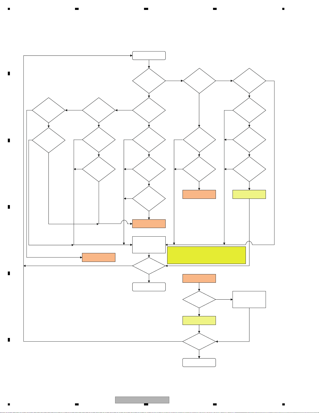
1234
1234
C
D
F
A
B
E
5.3 DIAGNOSIS FLOWCHART
Is the image
erroneous?
Go to FE-related
repair
FE part normal?
Can playback
start?
Is the sound
erroneous?
Repair defective parts
Normal?
Replace unit
NO
YES
YES
YES
NO
YES
YES
YES
YES
YES
YES
YES
YES
YES
YES
NO
NO
NO
Go to FE Check
NO
NO
NO
Replace unit
YES
Normal?
Go to FE Check
Go to FE Check
Go to FE Check
NO
YESYES
YES
YES
NO
NO
NO
START
END
END
NO
NO
NO
NO
NO
NO
NO
Does operation
take time?
YES
YES
*1) When a flash ROM generally needs to be
replaced by service, do not replace an IC but
a core unit (as no key or others is written in a
flash alone).
Flash life
OK?
Execute check 12
AVCC5 voltage
OK?
Execute check 8
AVCC5 voltage
OK?
Execute check 8
Video circuit
OK?
Execute check 11
DACCLK
normal?
Execute check 9
SDRAM IF
OK?
Execute check 6
STANBY
OK?
Execute check 1
VD8,VCC5
Power supply voltage OK?
Execute check 7
VSENS
OK?
Execute check 4
VDD5
(VCC33,VCC12)
Power supply voltage OK?
Execute check 2
RESET
OK?
Execute check 3
27 MHz
OK?
Execute check 5
Audio circuit
OK?
Execute check 10
NO
*1) Caution
Check Flow at MS7 Back End
40
AVH-P6300BT/XNUC
Page 41
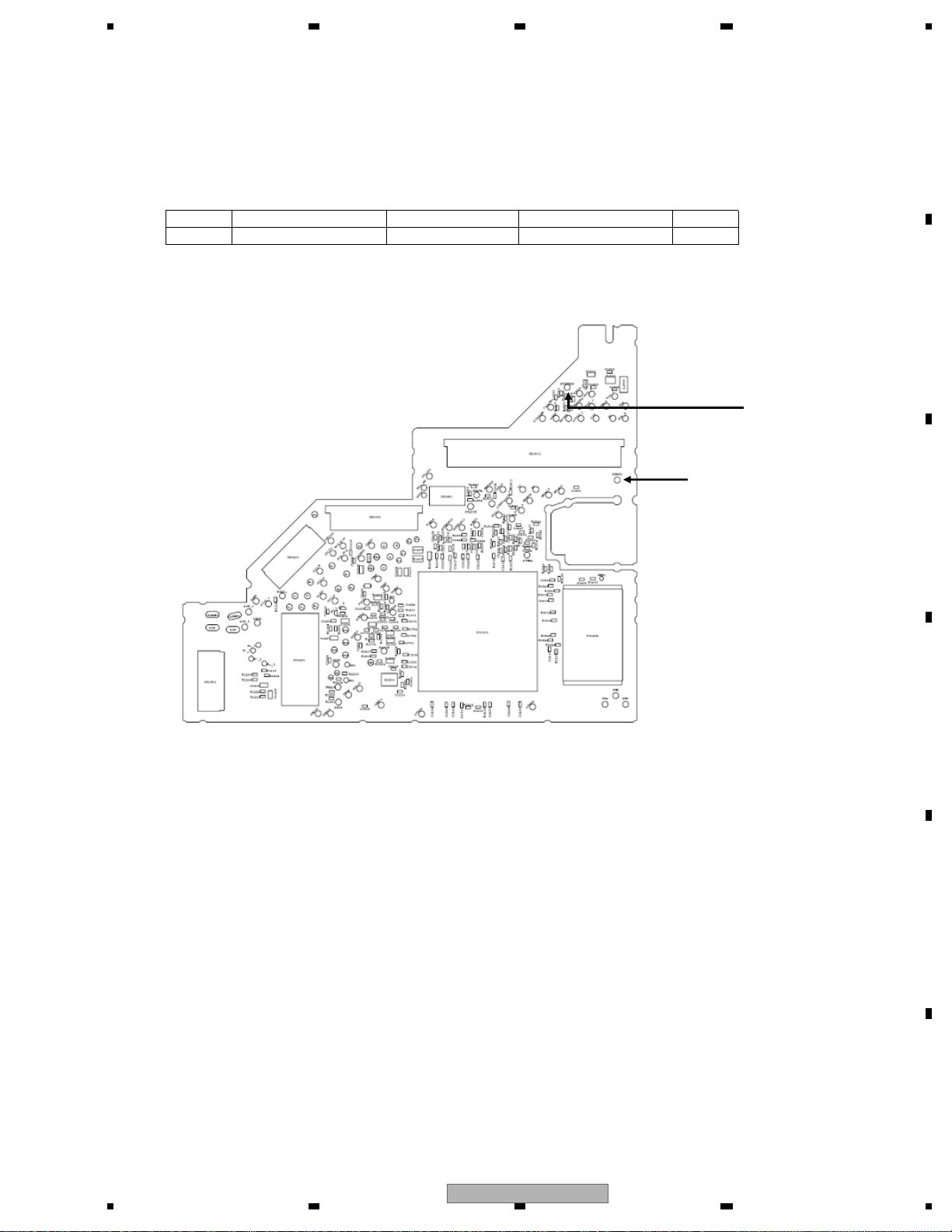
5678
56
7
8
C
D
F
A
B
E
<Check>
Check the voltage of the sending pin when the power is ON.
Checking should be based on DGND.
PCB side A
Fig. 1.1: Spots to check in STANDBY
STANDBY
DGND1
Check 1: STANBY OK?
NO. Spot to check Module NO. Rated value Unit
1 STANDBY-DGND1 ALL VCC33-0.6V or more V
AVH-P6300BT/XNUC
41
Page 42
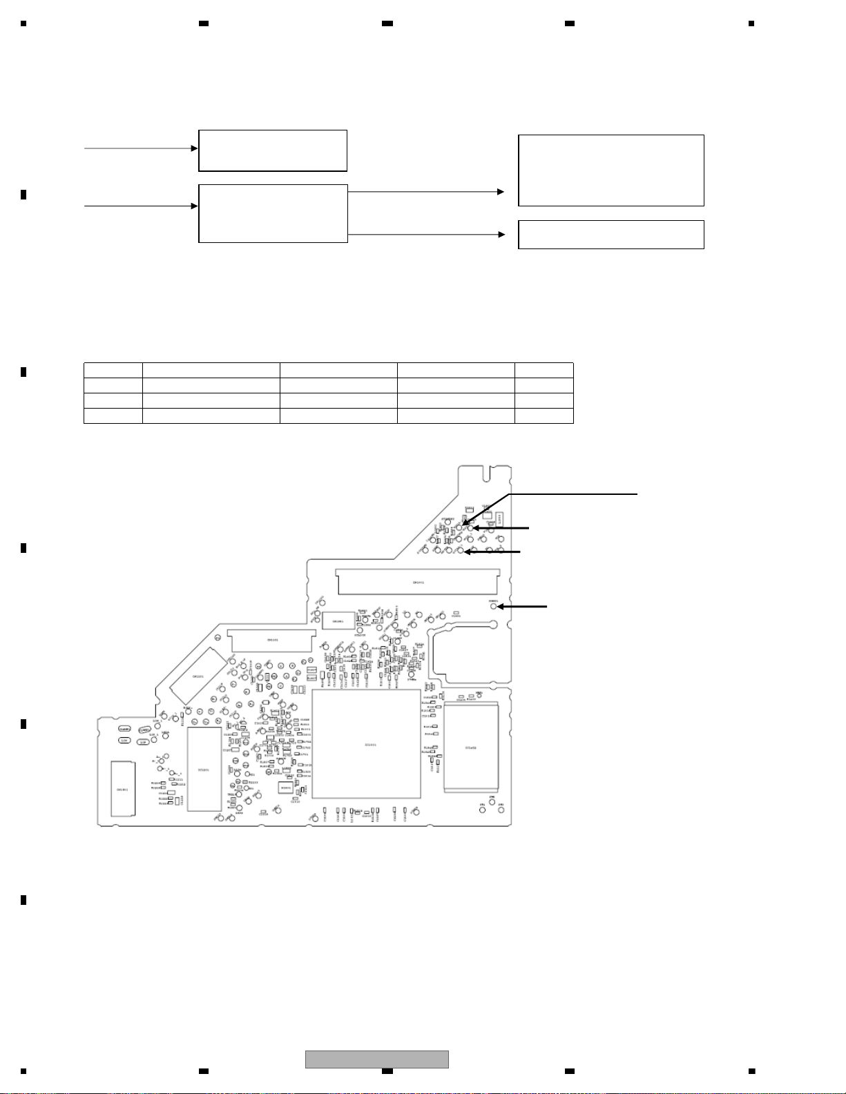
1234
1234
C
D
F
A
B
E
VDD8
VCC33 (= 3.3V)
VDD5
VCC12 (= 1.2V)
Fig. 2.1: Power configuration
<Check>
Check the voltage of the sending pin when the power is ON.
Checking should be based on DGND.
PCB side A
Fig. 2.2: Spots to check in VDD5, VCC33, VCC12 voltages
IC1401 FLASH power(Data)
IC1402 FLASH power(Program)
IC1480 SDRAM power
IC1501 DVD-LSI power
IC1501 DVD-LSI power
IC1004 and IC1005
DC/DC converter
VCC 3.3V/1.2V output
F.E. driver control system
DGND1
VCC33_1
VDD5_2
VCC12-1
Check 2: VDD5 (VCC33, VCC12) Power supply voltage OK?
NO. Spot to check Module NO. Rated value Unit
1 VDD5_2 - DGND1 ALL 5.0 ± 0.4 V
2 VCC33_1 - DGND1 ALL 3.3 ± 0.15 V
3 VCC12-1 - DGND1 ALL 1.2 ± 0.12 V
42
AVH-P6300BT/XNUC
Page 43
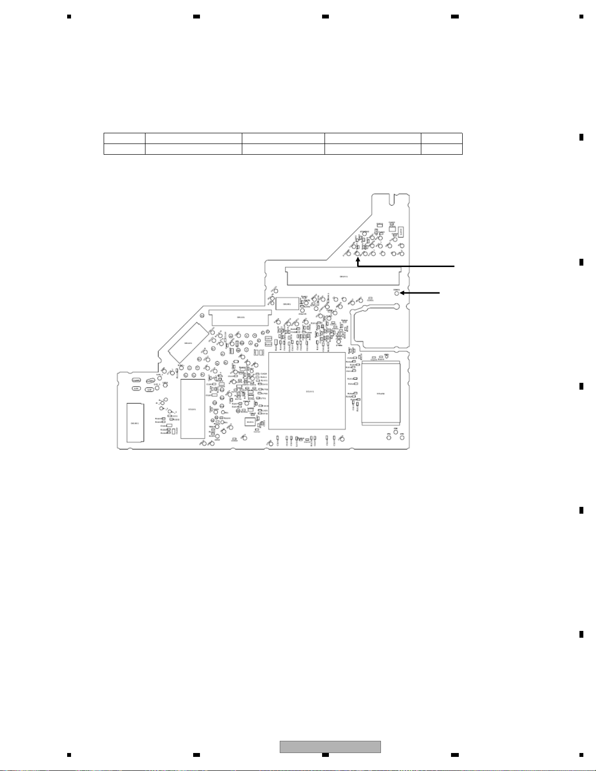
5678
56
7
8
C
D
F
A
B
E
<Check>
Check the voltage of the sending pin when the power is ON.
Checking should be based on DGND.
PCB side A
Fig. 3.1: Spots to check in RESET
DGND1
NRES
Check 3: RESET OK?
NO. Spot to check Module NO. Rated value Unit
1 NRES-DGND1 ALL VCC33 x 0.7 or more V
AVH-P6300BT/XNUC
43
Page 44
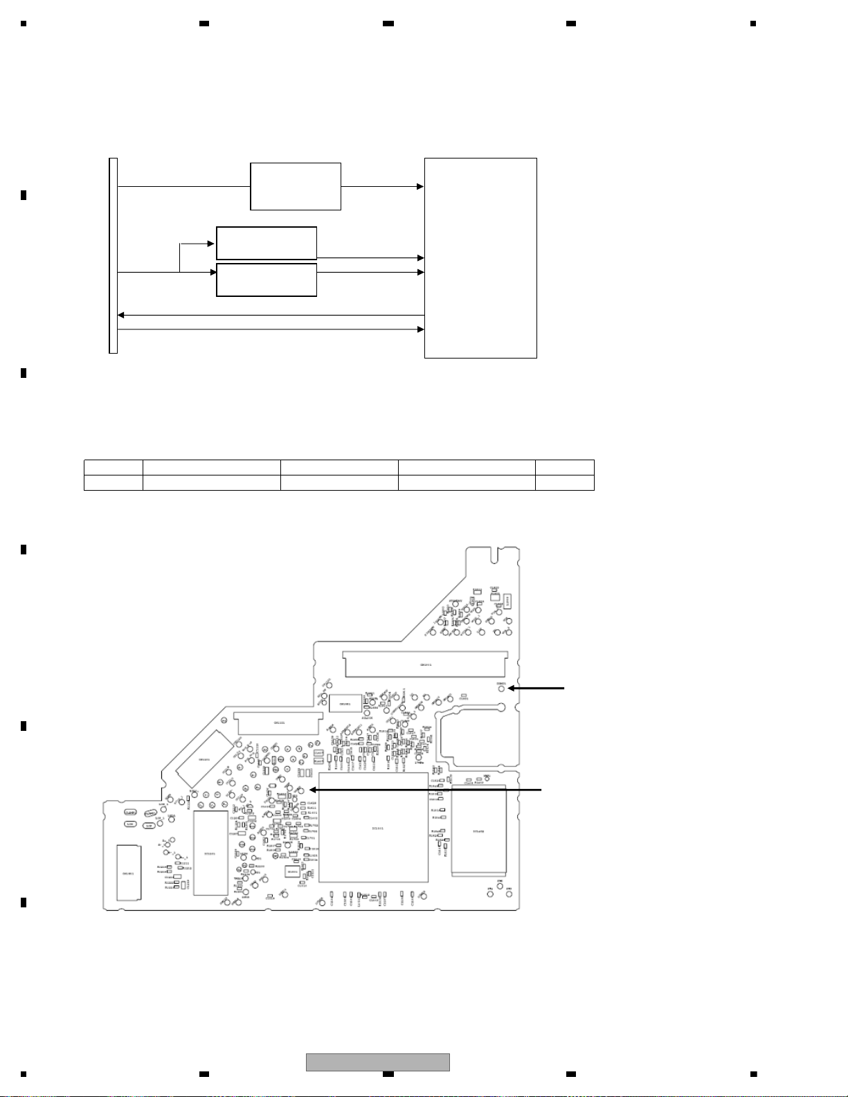
1234
1234
C
D
F
A
B
E
CN1901
HOST I/F
VSENSVD8
VDD5 VCC12
STANBY
NRES
Fig. 4.1: Power configuration and VSENS
<Check>
Check the voltage of the sending pin when the power is ON.
Checking should be based on DGND.
PCB side A
Fig. 4.2: Spots to check in VSENS
IC1501
DVD-LSI
IC1004
DC/DC converter
VSENS
DGND1
IC1005
regulator
R1550, R1551
voltage-dividing
circuits
Check 4: VSENS OK?
VCC33
NO. Spot to check Module NO. Rated value Unit
1 VSENS - DGND1 ALL VCC33 x 0.7 or more V
44
AVH-P6300BT/XNUC
Page 45
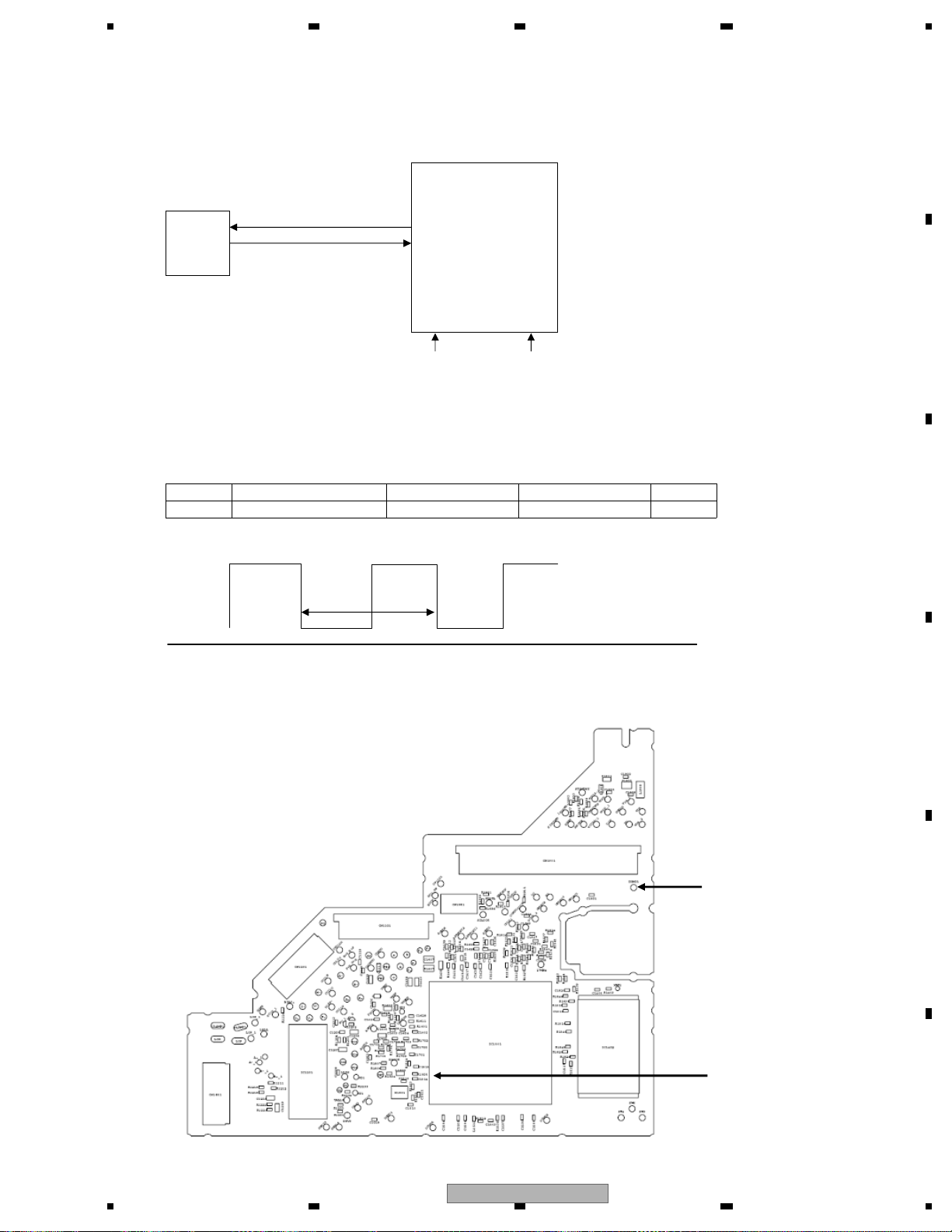
5678
56
7
8
C
D
F
A
B
E
Check 5: 27 MHz normal?
<Outline> Each CLOCK is created inside IC1501
using a 27 MHz crystal oscillator (X1501).
IC1501
DVD-LSI
X1501
OSCO
27 MHz
Crystal
OSCI
VCC12VCC33
Fig. 5.1: Clock configuration
<How to check>
Check based on DGND when the power is ON.
If NG is found, check the relevant lines, periphery of IC1501,
soldering of peripheral components and defective components.
NO. Spot to check Module NO. Rated value Unit
1 IC1501 156pin ALL 27 MHz ± 50ppm ppm
GND
PCB side A
Rated
value
Fig. 5.2: Rated value of a clock
DGND1
Fig. 5.3: Spots to check in 27 MHz
AVH-P6300BT/XNUC
IC1501 156pin
45
Page 46
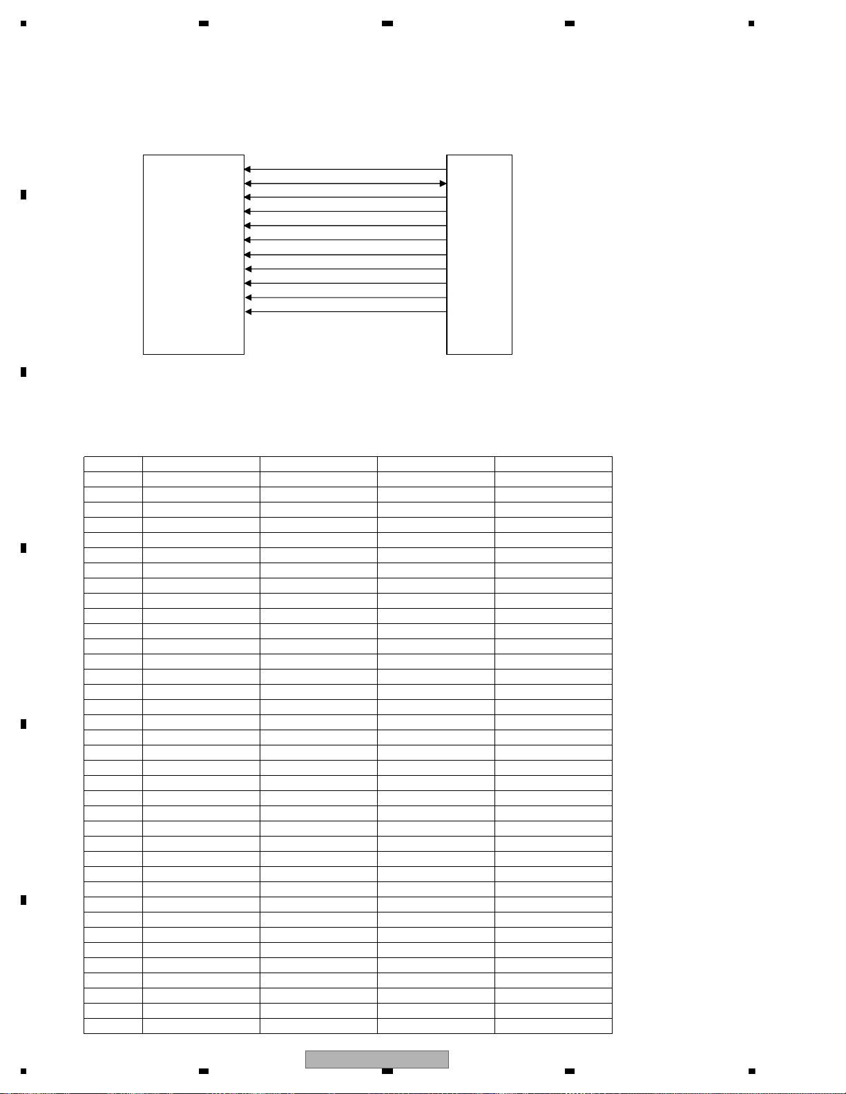
1234
1234
C
D
F
A
B
E
<Outline> The capacity of the communication I/F SDRAM between LSI and the memory should be
64 Mbit to assure the MPEG stream data as a buffer.
Note that XCSM, XWE, XCAS, XRAS and XCSM in IC1480 are called in a different manner
in IC1501 as NCSM, NWE, NCAS, NRAS and NCSM respectively.
MA0~11
MDQ0~15
MCK
XWE(NWE)
XCAS(NCAS)
XRAS(NRAS)
XCSM(NCSM)
DQM0
DQM1
BA0
BA1
Fig. 6.1: SDRAM I/F
<Check>
Check conduction between “Spot to check 1” and “Spot to check 2” when the power is OFF.
If NG is found, check soldering and defective components in all processes for “output -> input”
at the relevant spots.
IC
1480
SDRAM
IC1501
DVD-LSI
Check 6: SDRAM I/F OK?
NO. Signal name Spot to check 1 Spot to check 2 Rated value
1 MA0 IC1480 23pin IC1501 201pin 56 ohm ± 5%
2 MA1 IC1480 24pin IC1501 203pin 56 ohm ± 5%
3 MA2 IC1480 25pin IC1501 207pin 56 ohm ± 5%
4 MA3 IC1480 26pin IC1501 209pin 56 ohm ± 5%
5 MA4 IC1480 29pin IC1501 208pin 56 ohm ± 5%
6 MA5 IC1480 30pin IC1501 206pin 56 ohm ± 5%
7 MA6 IC1480 31pin IC1501 202pin 56 ohm ± 5%
8 MA7 IC1480 32pin IC1501 200pin 56 ohm ± 5%
9 MA8 IC1480 33pin IC1501 198pin 56 ohm ± 5%
10 MA9 IC1480 34pin IC1501 194pin 56 ohm ± 5%
11 MA10 IC1480 22pin IC1501 199pin 56 ohm ± 5%
12 MA11 IC1480 35pin IC1501 192pin 56 ohm ± 5%
13 MDQ0 IC1480 2pin IC1501 160pin 56 ohm ± 5%
14 MDQ1 IC1480 4pin IC1501 162pin 56 ohm ± 5%
15 MDQ2 IC1480 5pin IC1501 164pin 56 ohm ± 5%
16 MDQ3 IC1480 7pin IC1501 168pin 56 ohm ± 5%
17 MDQ4 IC1480 8pin IC1501 170pin 56 ohm ± 5%
18 MDQ5 IC1480 10pin IC1501 172pin 56 ohm ± 5%
19 MDQ6 IC1480 11pin IC1501 176pin 56 ohm ± 5%
20 MDQ7 IC1480 13pin IC1501 178pin 56 ohm ± 5%
21 MDQ8 IC1480 42pin IC1501 177pin 56 ohm ± 5%
22 MDQ9 IC1480 44pin IC1501 175pin 56 ohm ± 5%
23 MDQ10 IC1480 45pin IC1501 171pin 56 ohm ± 5%
24 MDQ11 IC1480 47pin IC1501 169pin 56 ohm ± 5%
25 MDQ12 IC1480 48pin IC1501 167pin 56 ohm ± 5%
26 MDQ13 IC1480 50pin IC1501 163pin 56 ohm ± 5%
27 MDQ14 IC1480 51pin IC1501 161pin 56 ohm ± 5%
28 MDQ15 IC1480 53pin IC1501 159pin 56 ohm ± 5%
29 MCK IC1480 38pin IC1501 183pin 105.7 ohm or less
30 XWE IC1480 16pin IC1501 181pin 56 ohm ± 5%
31 XCAS IC1480 17pin IC1501 188pin 56 ohm ± 5%
32 XRAS IC1480 18pin IC1501 189pin 56 ohm ± 5%
33 XCSM IC1480 19pin IC1501 190pin 56 ohm ± 5%
34 DQM0 IC1480 15pin IC1501 179pin 56 ohm ± 5%
35 DQM1 IC1480 39pin IC1501 180pin 56 ohm ± 5%
36 BA0 IC1480 20pin IC1501 193pin 56 ohm ± 5%
37 BA1 IC1480 21pin IC1501 197pin 56 ohm ± 5%
46
AVH-P6300BT/XNUC
Page 47
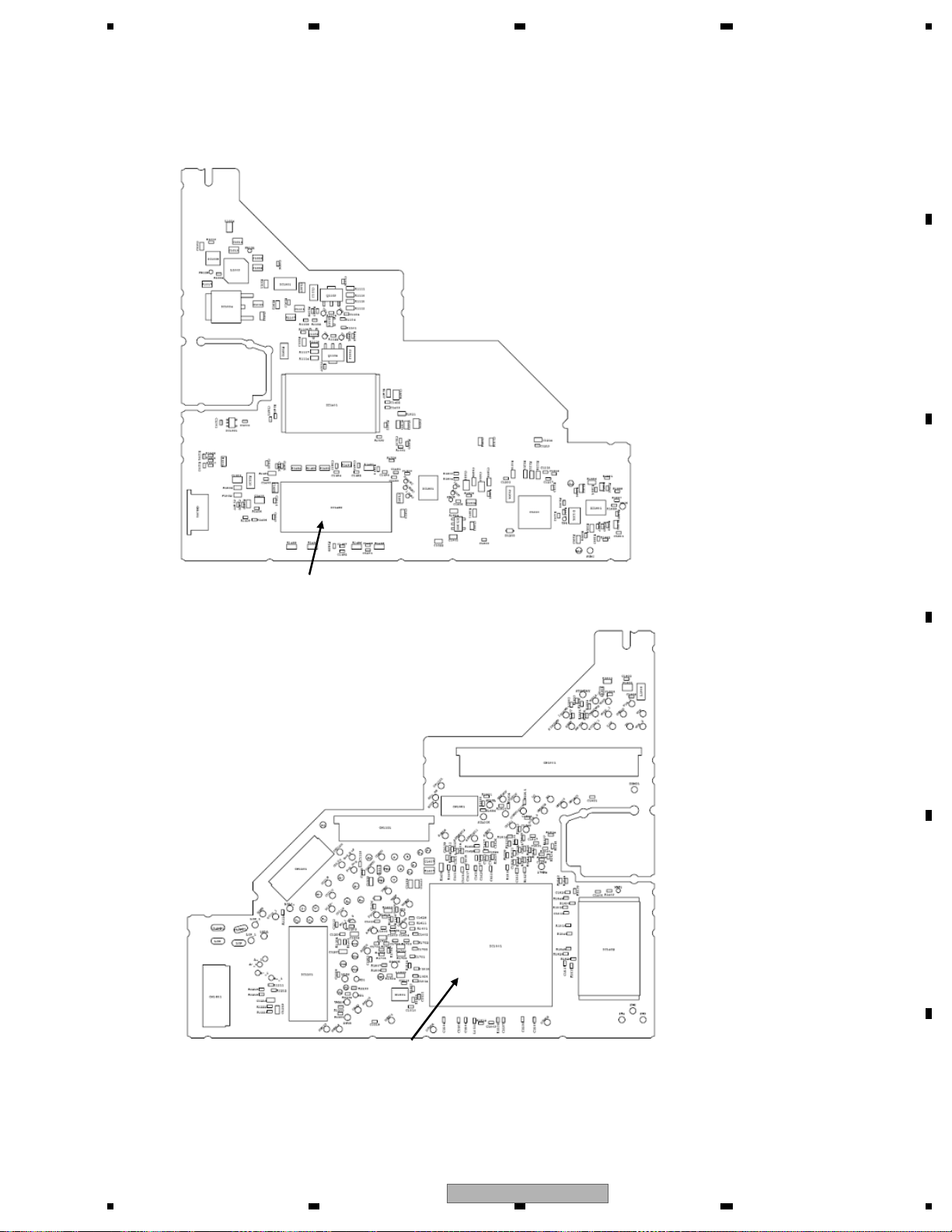
5678
56
7
8
C
D
F
A
B
E
PCB side B
Spot to check 1 (IC1480)
PCB side A
Spot to check 2 (IC1501)
Fig. 6.2: Spots to check in SDRAM I/F
AVH-P6300BT/XNUC
47
Page 48
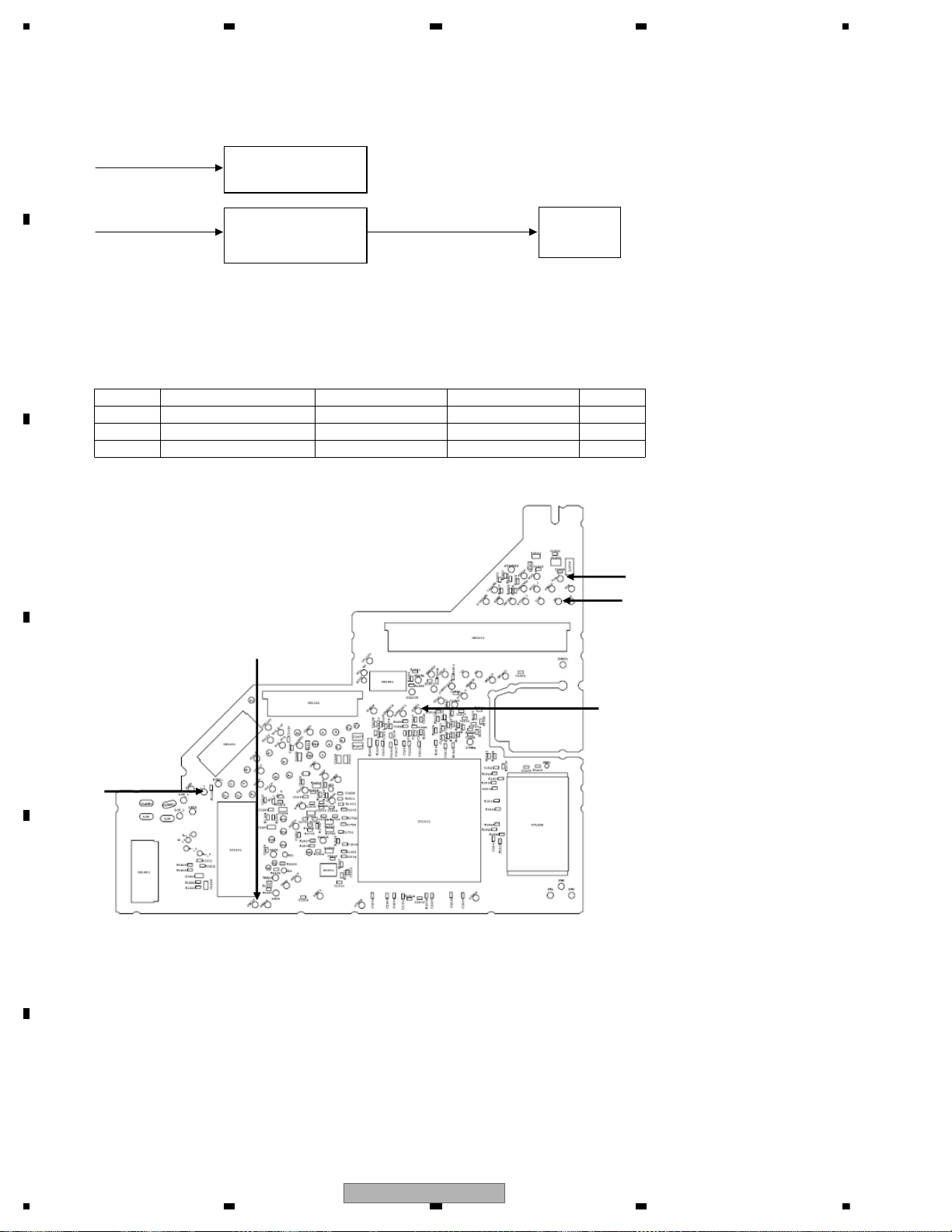
1234
1234
C
D
F
A
B
E
VD8_1
VCC5 (= 5.0 V)VD
Fig. 7.1: Power configuration
<Check>
Check the voltage of the sending pin when the power is ON.
Checking should be based on PGND, AGND.
PCB side A
Fig. 7.2: Spots to check in VD8, VCC5 voltages
F.E. driver system
PU power
IC1901
VCC 5V
REG IC
VD8_1
PGND3
VCC5_1
AGND1
VD
Check 7: VD8, VCC5 Power supply voltage OK?
NO. Spot to check Module NO. Rated value Unit
1 VD8_1 - PGND3 ALL 8.0 ± 0.4 V
2 VD - PGND_3 ALL 8.0 ± 0.4 V
3 VCC5_1 - AGND1 ALL 5.0 ± 0.1 V
48
AVH-P6300BT/XNUC
Page 49
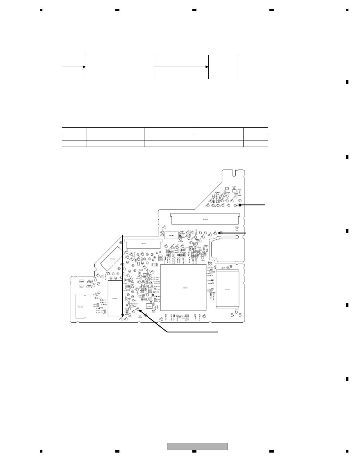
5678
56
7
8
C
D
F
A
B
E
VD AVCC5 (= 5.0 V )
Fig. 8.1: Power configuration
<Check>
Play back DVD-REF-A1 TITLE1 to check the voltage of the sending pin.
Checking should be based on PGND, AGND.
PCB side A
Fig. 8.2: Spots to check in VD8, AVCC5 voltages
IC1801
Audio-DAC
IC1900
AVCC 5V
REG IC
GNDAU1
AVCC5
VD
PGND3
Check 8: AVCC5 voltage OK?
NO. Spot to check Module NO. Rated value Unit
1 VD - PGND_3 ALL 8.0 ± 0.4 V
2 AVCC5 - GNDAU1 ALL 5.0 ± 0.1 V
AVH-P6300BT/XNUC
49
Page 50
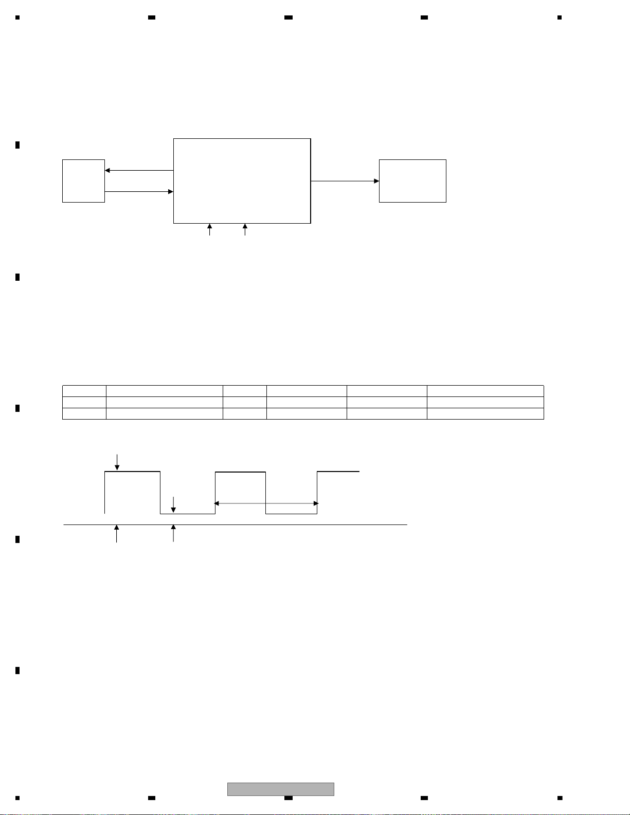
1234
1234
C
D
F
A
B
E
<Outline> DACCLK for Audio-DAC is created through IC1501
using a 27 MHz crystal oscillator (X1501).
DACCLK
Fig. 9.1: Clock configuration
<How to check>
DVD: DVD-REF-A1 TITLE 1
CD: Play back a general CDDA
Common in all modules compatible with DVD-V
Checking should be based on DGND.
If NG is found, check the relevant lines, periphery of IC1501,
soldering of peripheral components and defective components.
GND
Fig. 9.2: Rated value of a clock
IC1501
DVD-LSI
X1501
27 MHz
Crystal
IC1801
Audio-DAC
VCC12VCC33
Rated value 1
Rated
value 2
Rated
value 3
Check 9: DACCLK normal?
NO.
Spot to check 1 (sending pin)
Media Rated value 1 Rated value 2 Rated value 3
1 DACCK DVD 2.0 V~VCC33V DGND~0.8 V 36.8640 MHz ± 300 ppm
2 DACCK CD 2.0 V~VCC33V DGND~0.8 V 33.8688 MHz ± 300 ppm
50
AVH-P6300BT/XNUC
Page 51
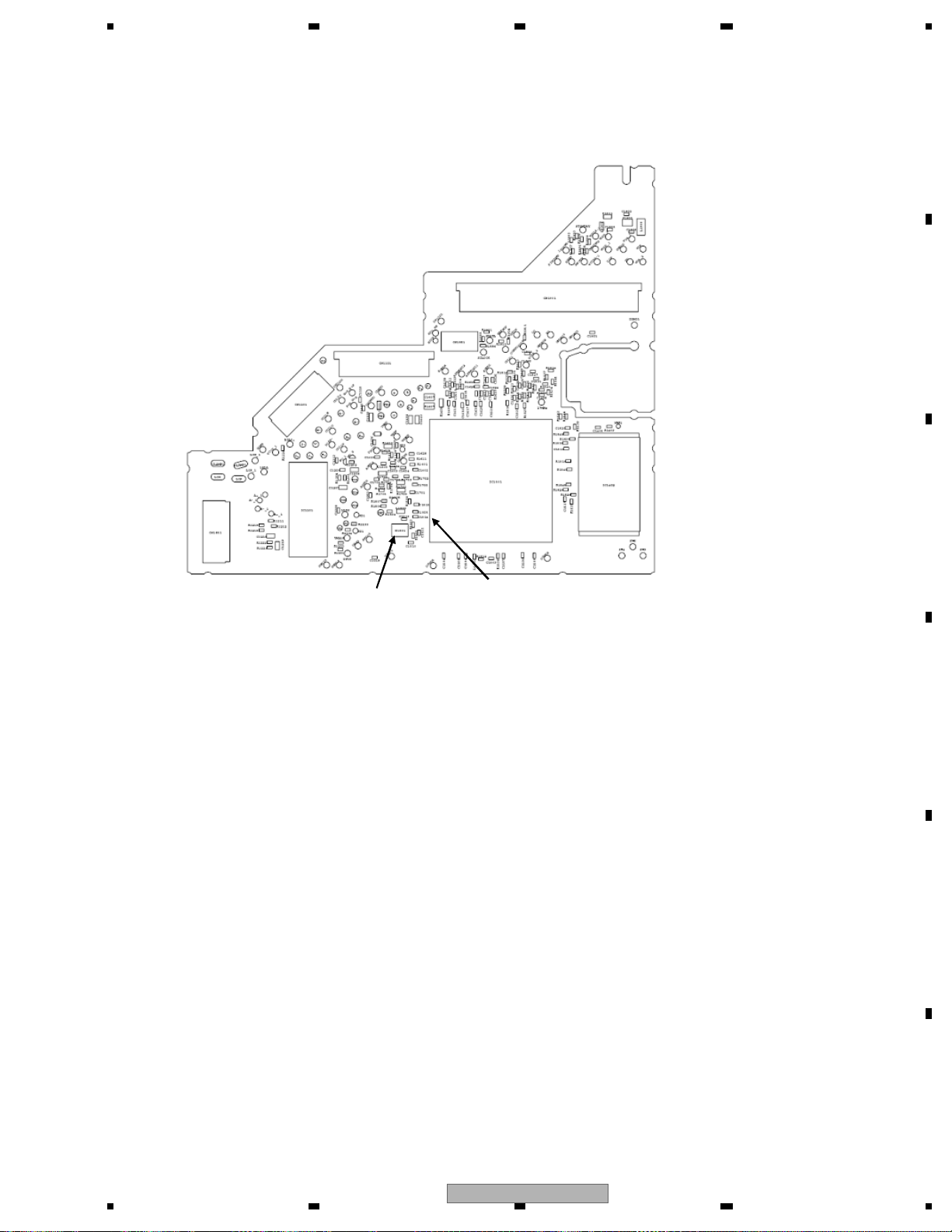
5678
56
7
8
C
D
F
A
B
E
PCB side A
Spot to check 2 (IC1501 148pin)
Spot to check 1 (probe)
Fig. 9.3: Spots to check in 27 MHz, DACCLK
AVH-P6300BT/XNUC
51
Page 52
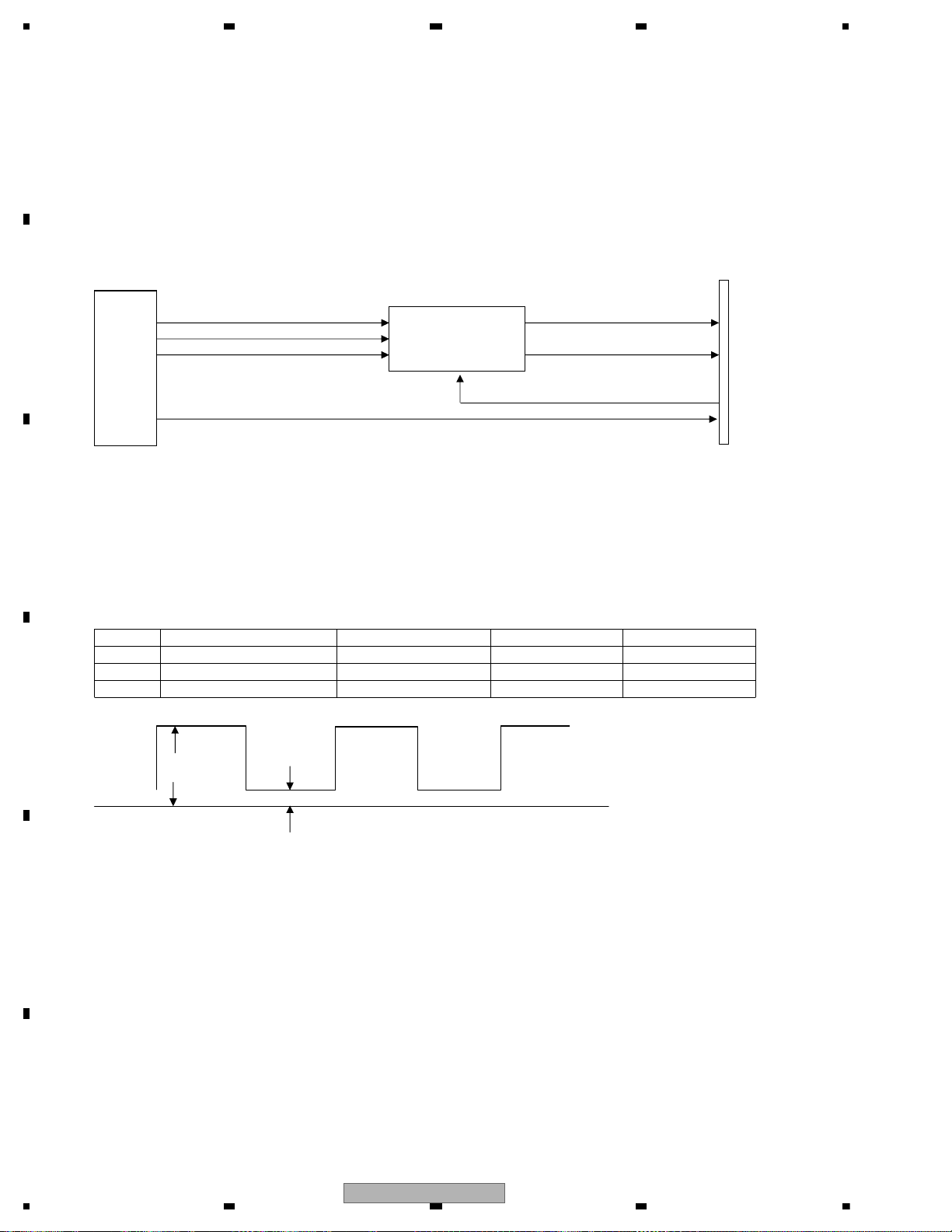
1234
1234
C
D
F
A
B
E
<Outline>The serial three-wire digital output +DACCLK that is output from DVD-LSI (IC1501) is converted
to the analog audio signal using Audio-DAC (IC1801), and the converted signal is output from
HOST I/F (CN1901).
Simultaneously, the analog MUTE signal is output through HOST I/F from DVD-LSI (IC1501).
The digital audio signal (IECOUT) output from DVD-LSI (IC1501) is output through CN1901.
CN1901
HOST I/F
LOLRCK
ADOUT
ROSRCK
GNDAU
IECOUT
Fig. 10.1: Audio circuit
<How to check>
Play back DVD-REF-A1 TITLE2 CHAPTER1 (48k/16bit 1kHz 0dB).
Checking should be based on DGND.
If NG is found, check the relevant lines, periphery of main components described above,
soldering of peripheral components and defective components.
GND
Fig. 10.2: Rated value of serial three wires
IC1801
Audio-DAC
IC1501
DVD-LSI
Rated value 1
Rated value 2
Check 10: Audio circuit OK?
NO.
Spot to check 1 (sending pin)
Rated value 1 Rated value 2
Reference waveform
1 ADOUT VCC33V-0.6V or more 0.4V or less Waveform 1
2 SRCK VCC33V-0.6V or more 0.4V or less Waveform 2
3 LRCK VCC33V-0.6V or more 0.4V or less Waveform 3
52
AVH-P6300BT/XNUC
Page 53
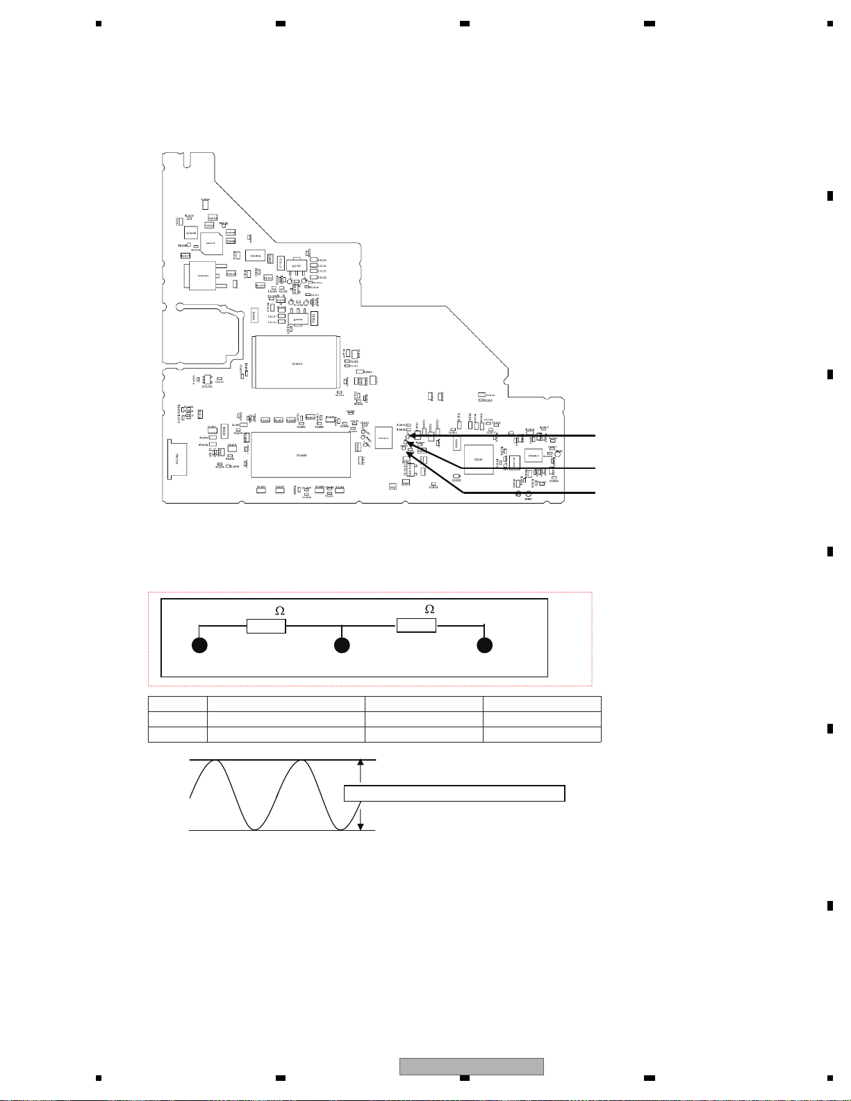
5678
56
7
8
C
D
F
A
B
E
PCB side B
Fig. 10.3: Spots to check for serial three wires
Perform the following check based on GNDAU2 using the measurement circuit
shown below:
Fig. 10.4: Rated value of analog audio out (LO, RO)
Rated value is an effective value (rms)
ADOUT
SRCK
LRCK
47 k
47 k
LO ROGNDAU2
NO.
Spot to check 1 (sending pin)
Rated value (rms)
Reference waveform
4LO 1400 ± 150 mV Waveform 4
5RO 1400 ± 150 mV Waveform 4
AVH-P6300BT/XNUC
53
Page 54
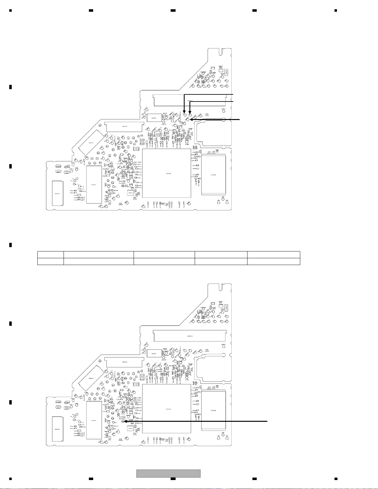
1234
1234
C
D
F
A
B
E
PCB side A
Fig. 10.5: Spots to check in analog audio out
Checking should be based on DGND.
Checking should be performed after connecting 24Pin FFC to the jig or other equipment.
PCB side A
Fig. 10.6: Spot to check in digital audio signal (IECOUT)
LO
RO
GNDAU
IEC
NO.
Spot to check 1 (sending pin)
Rated value 1 Rated value 2
Reference waveform
6 IEC VCC33V-0.6V or more 0.4V or less Waveform 5
54
AVH-P6300BT/XNUC
Page 55
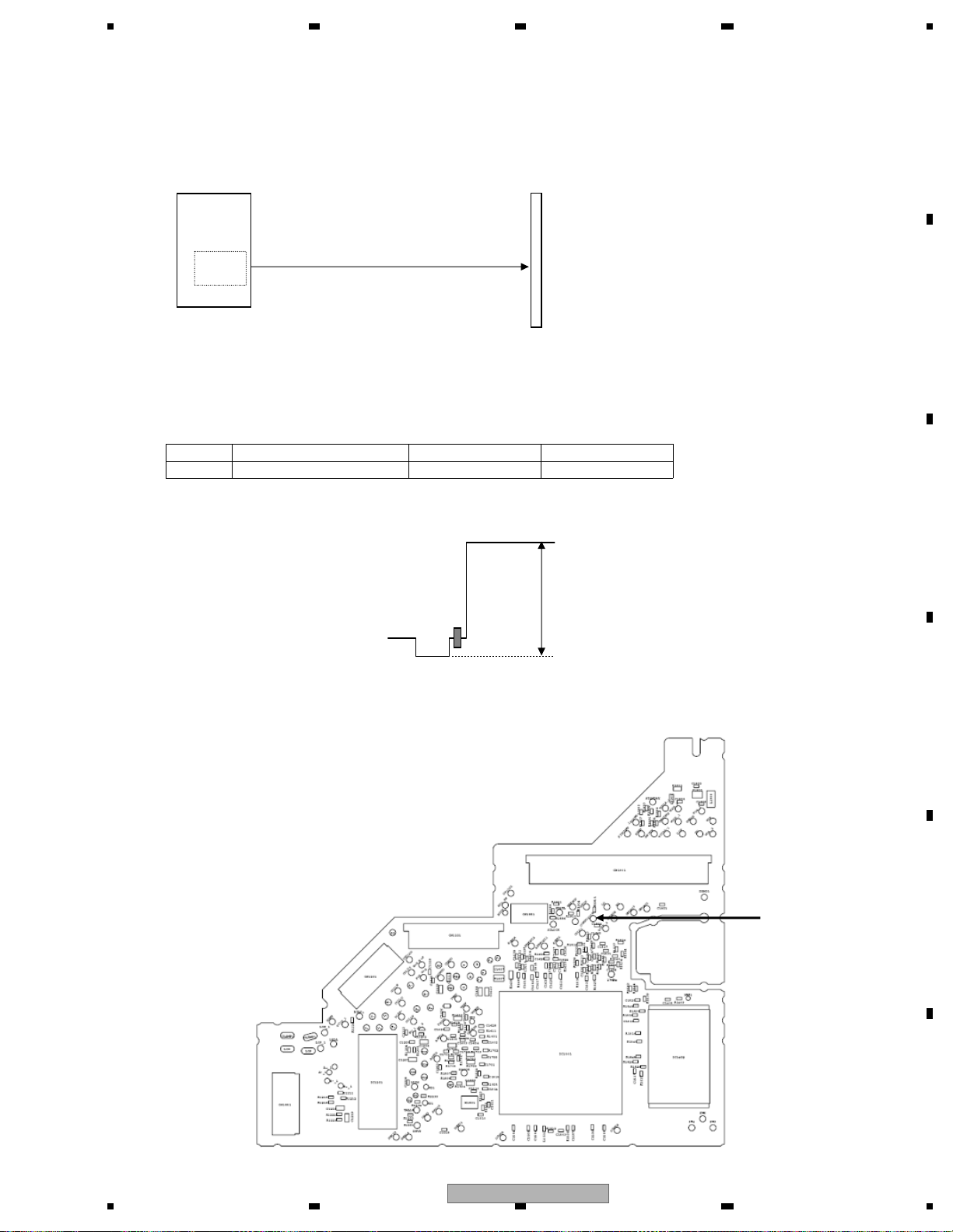
5678
56
7
8
C
D
F
A
B
E
Check 11: Video circuit OK?
<Outline>
A composite signal is output from DVD-LSI (IC1501)
and is output from HOST I/F (CN1901).
CN1901
HOST I/F
IC1501
DVD_LSI
COMPOSIT
Video
Composite
DAC
Fig. 11.1: Video circuit
<How to check>
Play back DVD-REF-A1 TITLE2 CHAPTER5 (WHITE 100IRE).
Monitor the COMPOSITE signal based on GNDV1 (sending pin) using an oscilloscope.
Set the Trigger mode and Trigger line to TV trigger and line 150 respectively.
NO.
Spot to check 1 (sending pin)
Rated value
Reference waveform
1 COMPOSITE 1000 mVpp ± 5 % Waveform 6
If NG is found, check the relevant lines, periphery of main components described above,
soldering of peripheral components and defective components.
PEAK
PCB side A
Rated valueCOMPOSITE signal
Color burst
Pedestal level
BOTTOM
Horizontal synchronous signal
Fig. 11.2: Waveform when 100% composite white is output
COMPOSITE
Fig. 11.5: Spot to check in VIDEO signal
AVH-P6300BT/XNUC
55
Page 56

1234
1234
C
D
F
A
B
E
To determine whether the FLASH memory has come to the end of its life
In case the user operation is poorly responded or the overall operation is heavy, the FLASH memory may have
reached the end of its life.
Whether the FLASH memory has reached the end of its life is determined by viewing the display of the LD live time.
1. Display the LD live time.
(For how to display the LD live time, see FE Test Mode)
2. The second digit of the live time from the left being E as in “*E** ****”
means the FLASH memory has reached the end of its life.
E.g.:
56
AVH-P6300BT/XNUC
Page 57
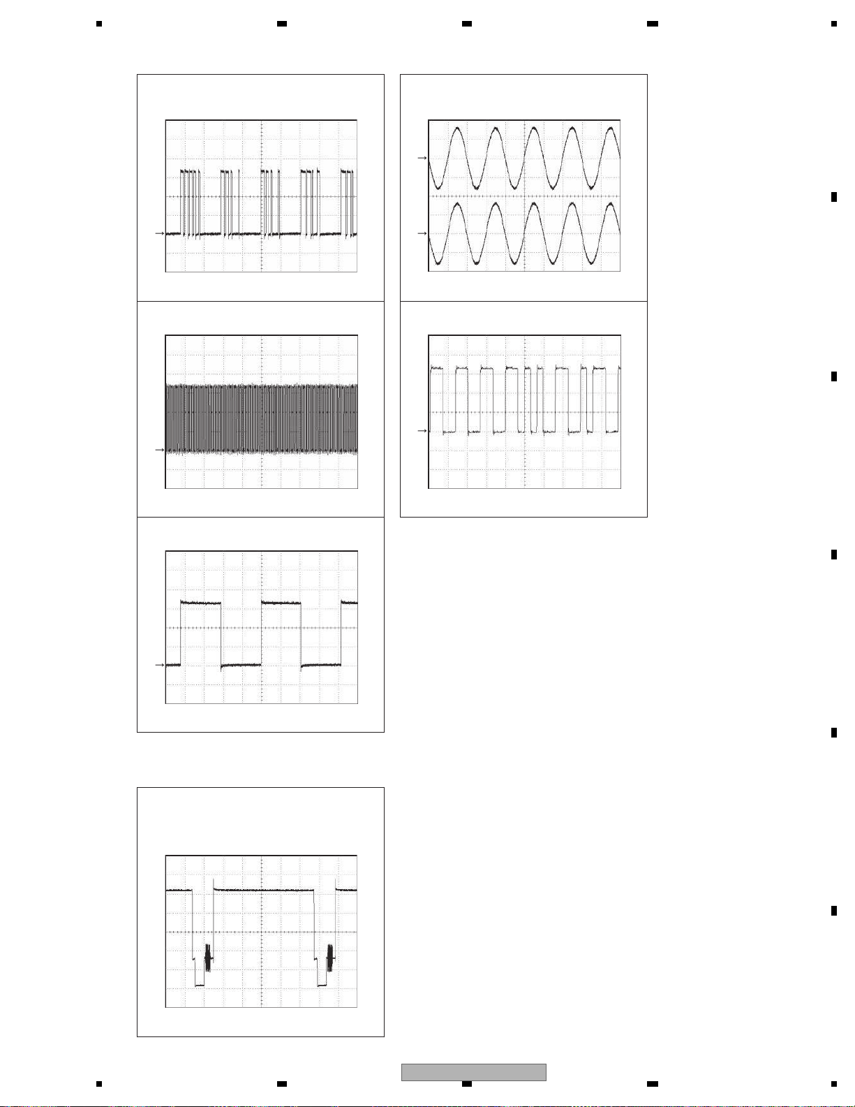
5678
56
7
8
C
D
F
A
B
E
AUDIO
CH1 : LO
1 V/div. 5 usec/divReference voltage: DGND2
G G
CH2 : ROCH1 : ADOUT3
Reference voltage: GNDAU2 1 V/div. 500 usec/div
G
Waveform 1
Reference voltage: DGND2 1 V/div. 5 usec/div
G
Waveform 2
CH1 : LRCK
G
1 V/div. 5 usec/divReference voltage: DGND2
Waveform 4
CH1 : IECOUTCH1 : SRCK
G
Waveform 5
1 V/div. 500 nsec/divReference voltage: DGND2
Waveform 3
VIDEO
[WHITE 100IRE]
CH1 : COMPOSITE
200 mV/div. 10 usec/divReference voltage: GNDV1
Waveform 6
AVH-P6300BT/XNUC
57
Page 58
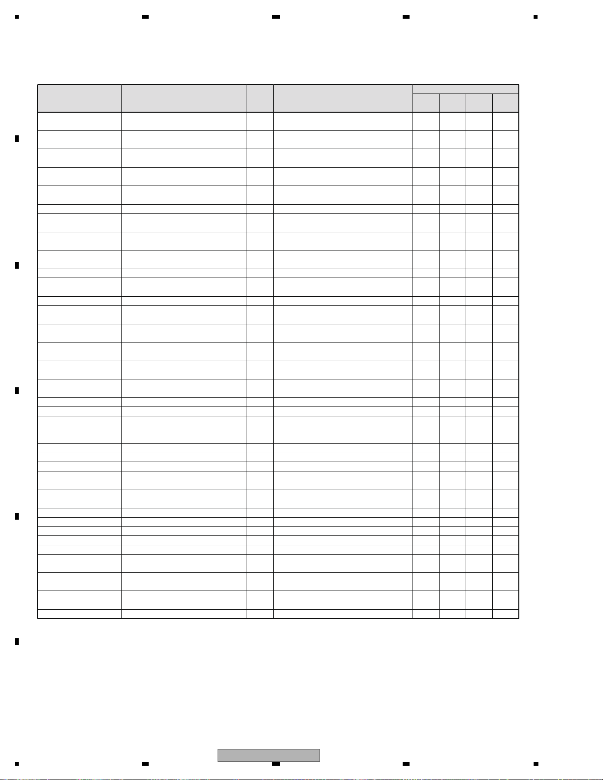
1234
1234
C
D
F
A
B
E
5.4 ERROR CODE LIST
Media Error UNPLAYABLE DISC 00h Discs of unplayable formats only X X X (Error status will be “No error”)
Open (No display) 10h Door open error * * * *
Read Error ERROR-02-99 20h Transfer start error X X X X
Focus Error (Focus Error
ERROR-02-90 21h Focus error X X X X
in mechanism set up)
Surface Error ERROR-02-9E 22h Focus error during setup (no focus has - - X been taken with the disc)
Address not found ERROR-02-80 23h No address is found X X X X
(Invalid Track)
Spindle Lock ERROR-02-91 24h Spindle lock NG (disc cannot rotate) X X X X
Carriage HOME ERROR-02-92 25h Carriage home NG (a pickup attempts X X X X
carriage home but stops unable to return)
ID/SUBCODE Read ERROR-02-94 26h ID/SUBCODE Read Error (ID/SUBCODE X X X X
Error not readable due to scratches, dirt, etc.)
AV CHIP decode Error ERROR-02-9A 2Ah AV CHIP decode NG (AV chip cannot X X X X
be decoded)
AV CHIP Recovery NG ERROR-02-9B 2Bh AV CHIP recovery NG X X X X
Error of PLAY BACK ERROR-02-9C 2Ch Playback status error (error due to X X X X
Mode Status software factor)
Disc Data Error ERROR-02-9D 2Dh Disc Data NG X X X X
Temp Error (In Case of THERMAL PROTECTION IN 30h High temperature (playback stops as the X - - High Temperature) MOTION
pickup temperature exceeds 89 degrees C)
No Disc (including Disc (No display) 40h No disc inserted (including disc loading/ * * * *
loading and ejecting) ejecting)
Loading_Mecha Error (No display) 50h Loading mechanical error (disc X - X cannot be clamped)
DRM Error PROTECTED DISC 70h DRM error (no all song can be played X X X back by DRM)
Region code Error DIFFERENT REGION DISC 90h Region code NG (playback impossible X X X due to different mechanical regions)
CPRM*7 Key Error *8 UNPLAYABLE DISC 93h Playback key error X - X REQUEST error ERROR-02-A0 A0h REQUEST error X X X X
Issuance of read ERROR-02-A1 A1h Issuance of read command failed X X X X
command failed (chip
dependent)
L0 adjustment NG ERROR-02-A2 A2h L0 adjustment NG X X X X
L1 adjustment NG ERROR-02-A3 A3h L1 adjustment NG X X X X
LD system NG ERROR-02-A4 A4h LD system NG X X X X
Gain adjustment system ERROR-02-A5 A5h Gain adjustment system NG X X X X
NG
Gain determination ERROR-02-A6 A6h Gain determination system NG X X X X
system NG
Servo initial setting NG ERROR-02-A7 A7h Servo initial setting NG X X X X
Disc unclamped ERROR-02-A8 A8h Disc unclamped X X X X
Tracking system NG ERROR-02-A9 A9h Tracking system NG X X X X
Media setting system NG
ERROR-02-AA AAh Media setting system NG X X X X
Focus Error ERROR-02-AB ABh JUMP between layers NG X X X X
Error of PLAY BACK ERROR-02-B0 B0h Navigation command error X X X X
Mode Status
Error of PLAY BACK ERROR-02-B1 B1h Retry over X X X X
Mode Status
DivX DRM Inofrmation ERROR-02-C1 C1h DivX DRM information update error X - - Update Error *10
Undefined Error ERROR-FF-FF FFh Undefined error X X X X
How to restore
UART ACC Source Eject Play
Error status OSD *1 *2 Meaning Off/On Off/On Key
LIST OF ERRORS
X: An error is cancelled by operation. -: No error is cancelled by operation. *: No setting
*1 Contents displayed in OSD. The articles with several display patterns have the upper line with the Japanese version of Full GUI, and the lower
line with the Touch Panel model and Full GUI (English version).
*2 Parameter sent by the DVD mecha, on the UART command such as “Notify reception error”. See Chapter 2 for details.
*3 CPPM (Content Protection for Prerecorded Media): Copyright technology used in DVD-A. This is achieved with the keys recorded in the media
as well as the device keys the player has.
*4 Available only for the models compatible with DVD-A.
In case of an error, the audio output will be muted only but the playback operation will continue. Also, acceptance of the user operation will be
the same as normal.
58
AVH-P6300BT/XNUC
Page 59

5678
56
7
8
C
D
F
A
B
E
*5 AWM (Audio Watermark): Electronic watermark where the information on the owner of copyright or CCI (Copy Control Information) is included
for determination of illegally copied discs or other means.
*6 No notice as an error status will be conducted, but error occurrence will be notified in the operation status notice. See Chapter 2 for details.
*7 CPRM (Content Protection for Recordable Media): Copyright technology for the digital contents used for recordable DVDs or memory cards.
*8 Available only for the models compatible with DVD-VR
*9 This occurs when the audio property information notice is sent from the DVD mecha but no audio property activation notice is returned.
The time taken for occurrence should be specified in the latency time for the audio property notice set in the connection confirmation command.
*10 This occurs when the DRM information update notice is sent from the DVD mecha but no DRM information update response is returned.
External storage device (USB, SD)
Message Cause Action
Unplayable
File
This type offile
cannot be played
on this unit.
Select a filethat
can be played.
There are no
songs.
Transferthe audio
files to theexternal
storage device and
connect.
Security for the
connected USB
memory is enabled.
Follow theUSB
memory instructions to disablesecurity.
Format Read Sometimesthere
is a delaybetween the startof
playback and
when you startto
hear any sound.
Wait untilthe message disappears
and you hear
sound.
Skipped The connected
external storage
device contains
WMA files that
are protected by
Windows Media DRM 9/10.
Play an audiofile
not embedded with
Windows Media
DRM 9/10.
Protect All the files on
the connected
external storage
device is protected by
Windows Media
DRM 9/10.
Transferaudio files
not protected by
Windows Media
DRM 9/10 tothe
external storage
device and connect.
Incompatible
USB
The USB device
connected to is
not supported by
this unit.
Connect a USB
portable audio
player or USB
memory that is
USB Mass Storage
Class compliant.
The USB device
is not formatted
with FAT16 or
FAT32.
The connected
USB device should
be formatted with
FAT16or FAT32.
IncompatibleSDUnsupported SD
card is inserted.
Use the supported
SD card.
Non-compatible
SD storage device
Remove your device and replaceit
with a compatible
SD storage device.
Message Cause Action
Check USB TheUSB connec-
tor or USBcable
has shortcircuited.
Check that the
USB connector or
USB cable isnot
caught in something or damaged.
The connected
USB portable
audio player/
USB memory
consumes more
than maximum
allowable current.
Disconnect the
USB portable
audio player/USB
memory and do
not use it.Turn the
ignition switch to
OFF, then to ACC
or ON andthen
connect a compliant USB portable
audio player/USB
memory.
Error-02-9X/-DXCommunication
failed.
Perform one ofthe
following operations.
–Turnthe ignition
switch OFFand
back ON.
–Disconnect the
USB portable
audio player/USB
memory.
–Change to adifferent source.
Then, return tothe
USB portable
audio player/USB
memory.
Rental Expired.
The inserted external storage device contains
expired DivX
VOD content.
Select a filethat
can be played.
Video resolution not supported
The inserted external storage device contains a
high definition
DivX file.
Select a filethat
can be played.
It is notpossible to writeit
in the flash.
Flash memory
error.
Replace the flash
memory.
Yourdevice is
not authorized to play
this DivX protected video.
This unit’s DivX
registration code
has not been
authorized by the
DivX VOD contents provider.
Register this unit
to the DivXVOD
contents provider.
Format Read Sometimesthere
is a delaybetween the startof
playback and
when you startto
hear any sound.
Wait untilthe message disappears
and you hear
sound.
Video frame
rate not supported.
DivX file’s frame
rate is morethan
30 fps.
Select a filethat
can be played.
Audio Format
not supported.
This type offile is
not supported on
this unit.
Select a filethat
can
be
played.
™
AVH-P6300BT/XNUC
59
Page 60

1234
1234
C
D
F
A
B
E
iTunes tagging
Message Cause Action
iPod full. Tags
not transferred.
Memory used for
tag information
on the iPod is
full.
Sync the iPodwith
iTunesand clean
up the taggedplaylist.
Memory full.
Tags not
stored.
This unit’s flash
memory used as
the temporary
storage area is
full.
Connect the iPod
to this unitand
transfer this unit’s
tag information to
the iPod.
Tags transferred failed.
This unit’s taginformation cannot
transfer to the
iPod.
Check the iPod
and try again.
Tag store
failed.
Taginformation
cannot be stored
in this unit.
Tryagain.
Error-8D Built-in FLASH
ROM encountered an error
Turnthe ignition
OFFandON.
SD source cannot be selected during
tag transfer.
Taginformation
is being transferred to the
iPod.
Wait untiltag
transfer is complete.
Bluetooth
Message Cause Action
Error-10 The power failed
for the Bluetooth
module of this
unit.
Turnthe ignition
switch OFFand
then to ACCor ON.
If the errormessage is stilldisplayed after
performing the
above action,
please contact
your dealer oran
authorized Pioneer
Service Station.
Pandora
Message Cause Action
Error-19 Communication
failed.
Disconnect the
cable from the
iPod.Once the
iPod’smainmenu
is displayed, reconnect the iPod and
reset it.
Start up the
Pandora Application from
your Device.
The Pandoraapplication has not
started running
yet.
Start up the
Pandoraapplication from your
iPod/iPhone.
Unable to
save thumb
rating. Try
again later.
Unable to save
thumb rating.
Tryagainlater.
Unable to
save Bookmark. Try
again later.
Unable to save
Bookmark.
Tryagainlater.
Pandora system maintenance. Try
again later.
Pandorasystem
is undergoing
maintenance.
Tryagainlater.
Skip limit
reached.
Skip limit
reached.
Do not exceedthe
skip limit.
This version
of the
Pandora Application is
not supported.
This version of
the Pandoraapplication is not
supported.
Connect an iPod/
iPhone that hasa
compatible version
of the Pandora application installed.
Check Device Device error mes-
sage displayed in
PandoraApplication.
Please check your
iPod/iPhone.
Pandora is unable to play
music. Please
see your Device.
Unable to play
music from
Pandora.
Please check your
iPod/iPhone.
Create station
within the
Pandora Application on
Device.
No station found. Create a station in
the Pandoraapplication on your
iPod/iPhone.
No Active Station
No station selected.
Select a station.
iPod
Message Cause Action
Format Read Sometimesthere
is a delaybetween the startof
playback and
when you startto
hear any sound.
Wait untilthe message disappears
and you hear
sound.
Error-02-6X/9X/-DX
Communication
failed.
Disconnect the
cable from the
iPod.Once the
iPod’smainmenu
is displayed, reconnect the iPod and
reset it.
iPod failure. Disconnect the
cable from the
iPod.Once the
iPod’smainmenu
is displayed, reconnect the iPod and
reset it.
Error-02-67 The iPodfirm-
ware version is
old.
Update the iPod
version.
Stop There are no
songs.
Transfersongs to
the iPod.
There are no
songs in thecurrent list.
Select a listthat
contains songs.
Not Found No related
songs.
Transfersongs to
the iPod.
60
AVH-P6300BT/XNUC
Page 61
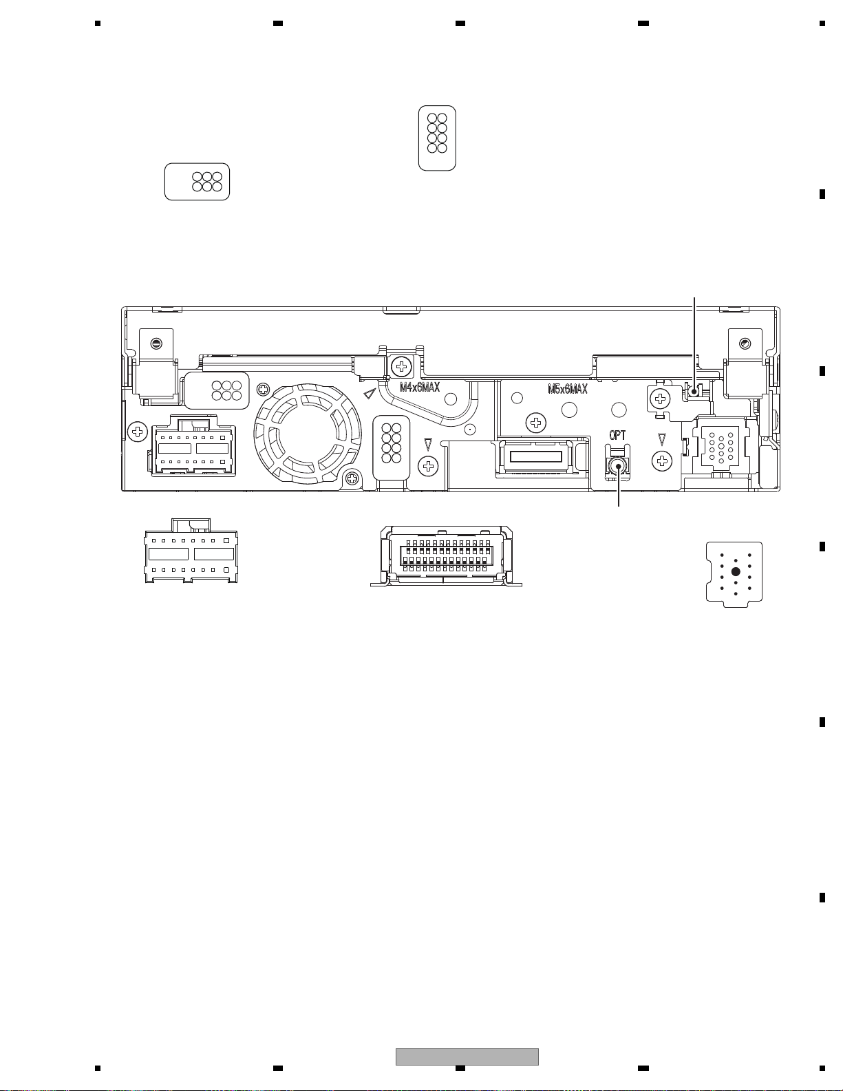
5678
56
7
8
C
D
F
A
B
E
1
2
7
8
1. REAR AUDIO OUTPUT
2. WIRED REMOTE INPUT
3. AUDIO INPUT L
4. BT MIC
5. AUDIO INPUT R
6. REAR VIEW CAMERA INPUT
7. REAR MONITOR OUTPUT
8. VIDEO INPUT
1. FL-
2. RL-
3. FL+
4. RL+
5. FR-
6. RR-
7. FR+
8. RR+
9. P.B.
10. BGSENS
11. ACC
12. B.REM
13. ILM
14. MUTE
15. B.UP
16. GND
16
15
2
1
1
2
5
6
1. SUBWOOFER OUTPUT R
2. SYBWOOFER OUTPUT L
3. REAR OUTPUT R
4. REAR OUTPUT L
5. FRONT OUTPUT R
6. FRONT OUTPUT L
11
10
9
8
7
6
5
4
3
2
1
IP-BUS INPUT
1. BUS+
2. BUSG
3. BUSLG
4. NC
5. BUS-
6. BUSRG
7. BUSL+
8. ASENBO
9. BUSR+
10. BUSR-
11. BUSL-
1. CCR
2. CCG
3. CCB
4. CCSYNC
5. GNDSIG
6. NC
7. NC
8. NC
9. ASENB
10. NC
11. NC
12. NC
13. ONSEI+
14. ONSEI-
15. NC
16. NC
17. NC
18. NC
19. DSEN
20. TVON
21. GION
22. NC
23. NC
24. SYS_TO_NAVI
25. NAVI_TO SYS
26. GNDD
RGB IN
1
2
25
26
OPTICAL OUTPUT
(RD, RI model only)
ANTENNA
5.5 CONNECTOR FUNCTION DESCRIPTION
AVH-P6300BT/XNUC
61
Page 62
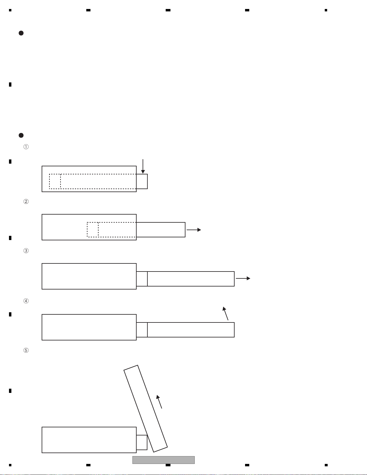
1234
1234
C
D
F
A
B
E
5.6 MECHANICAL DESCRIPTION
1. The operation is carried out with two motors; motor for anteroposterior driving (CXC6638) and motor for angle
driving (CXC6639).
2. The analog potential generated from the angle encoder is detected for detecting the angle operation status and
the operation position.
3. The angle last position memory function is memorized by microcomputer using 256-resolution STEP of VDD.
4. The pulse is detected by photo interrupter for detecting the horizontal operation status.
5. When the reset is started, the discharge operation is carried out again after the storage status and the system
enters the startup status.
6. The angle is adjusted with angle keys ( + / - ).
7. The storage and the discharge of monitor is carried out with OPEN/CLOSE key and the temporal tilting of monitor
is carried out with temporal tilting key.
8. The monitor automatic storage and discharge ON/OFF and setback ON/OFF at ACC ON/OFF is set from the
navigation menu screen.
If ACC is set to ON when OPEN key is pressed or the automatic opening and closing setting is ON, the motor
for angle driving is rotated to 0° direction for 500 ms (imposition).
500 ms later, the motor for angle driving is stopped and the motor for anteroposterior driving is rotated to the
discharge direction.
The motor for anteroposterior driving is continuously rotated to the discharge direction for 600 ms after LIFTSW
changes from H to L.
600 ms later, the motor for anteroposterior driving is stopped and the motor for angle driving is rotated to UP
direction.
If the angle VOL voltage becomes approximately 90° voltage, the discharge is completed by braking the motor
for angle driving. (If the previous angle is memorized, the operation is carried out with the angle)
90° voltage or last memory position
Outline of FLAP operation
Explanation on FLAP discharge operation
62
AVH-P6300BT/XNUC
Page 63
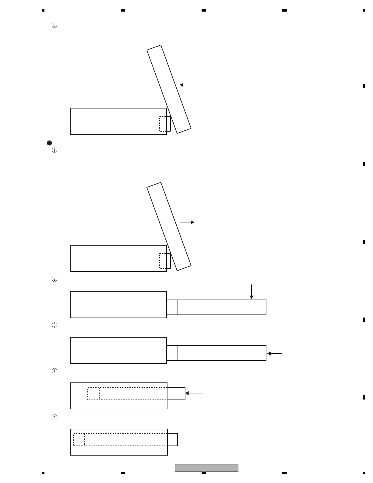
5678
56
7
8
C
D
F
A
B
E
When the setback is set to ON, the motor for angle driving is braked after the monitor angle voltage reaches the
previous angle memory, and then the motor for anteroposterior driving is rotated to the storage direction in low
speed. After that, if LIFTPULSE changes from L to H, the motor for anteroposterior driving is stopped.
Explanation on FLAP storage operation
In six seconds after ACC is turned OFF when CLOSE key is pressed or the automatic opening and closing
setting is ON, the motor for angle driving is rotated to 0° direction.
When the setback is set to ON, the motor for anteroposterior driving is rotated to the discharge direction in high
speed and the motor is continuously rotated for 600 ms after LIFTSW changes from H to L, and then the motor
for angle driving is rotated to 0° direction.
The motor for angle driving is rotated to 0° direction for 900 ms after DEG0SW changes from H to L and the
imposition operation is carried out.
900 ms later, the motor for angle driving is braked and the motor for anteroposterior driving is rotated to the
storage direction.
After the horizontal operation status detection pulse is detected 15 times, the motor for anteroposterior driving is
rotated to the storage direction in low speed.
If the horizontal operation status detection pulse cannot be detected for 600 ms, the brake is operated and the
monitor storage is completed.
AVH-P6300BT/XNUC
63
Page 64
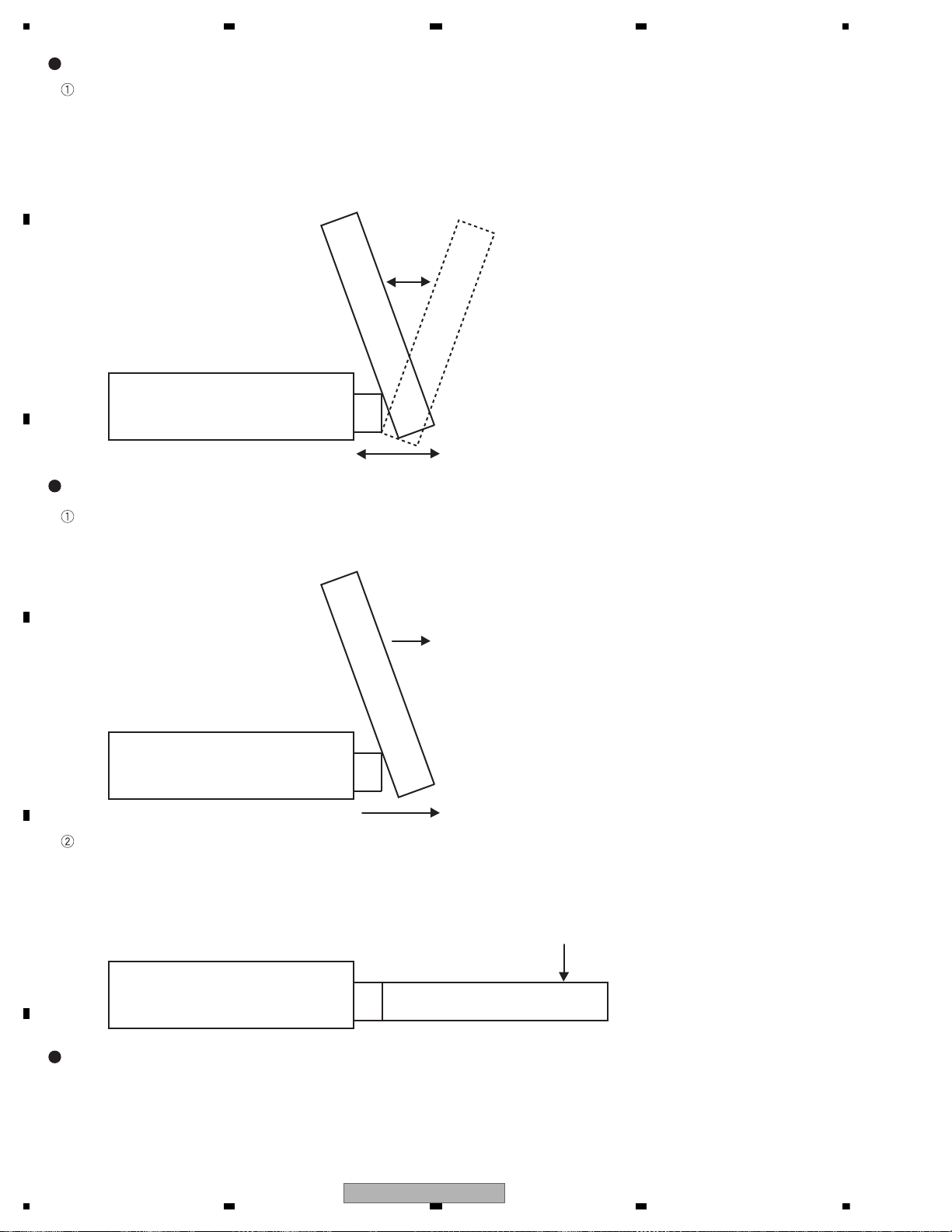
1234
1234
C
D
F
A
B
E
The motor for angle driving is rotated to UP direction and DOWN direction by + key and – key, respectively from
the monitor stop position. If you keep pressing the key, the monitor carries out the continuous angle operation
from approximately 50 to 110° without step. When the setback is set to ON, pressing the key rotates the motor
for anteroposterior driving in the horizontal discharge direction and the angle is adjusted by changing the angle
voltage only for the effective portion of angle adjustment key in 600 ms after LIFTSW changes from H to L. In
three seconds after the adjustment, the motor for anteroposterior driving is rotated in the horizontal storage
direction in low speed and the brake is operated after LIFTPULSE changes from L to H.
Pressing the temporal tilting key from the monitor stop position rotates the motor for angle driving to 0° direction.
When the setback is set to ON, pressing the key rotates the motor for anteroposterior driving and the brake is
operated in 600 ms after LIFTSW changes from H to L, and then the motor for angle driving is rotated in 0°
direction.
The motor for angle driving is rotated for 900 ms after DEG0SW changes from H to L, and the monitor is stopped
at the horizontal position by brake. In seven seconds after that, the navigation system operation sound sounds
three times in one second intervals and in ten seconds, the motor for angle driving rotates in angle UP direction
and the brake stops at the last memory position. When the setback is set to ON, the motor for angle driving is
stopped at the last memory position, and then the motor for anteroposterior driving rotates in the horizontal
storage direction in low speed and the motor is stopped after LIFTSW changes from L to H.
1. For the angle position, the angle voltage should be checked all the time and the last memory should be
memorized by addition and subtraction of voltage. However, if the monitor is forcibly moved with hands etc., it is
not memorized.
2. If the predefined pulse cannot be detected during the horizontal operation, the operation should be stopped at
that point.
Explanation on FLAP angle adjustment
Explanation on FLAP temporal tilting operation
Precautions on FLAP operation
64
AVH-P6300BT/XNUC
Page 65
5678
56
7
8
C
D
F
A
B
E
BackUp is interrupted temporarily, operation by Acc OFF/ON
0
Flap position is stopped
indeterminately
BackUp is
interrupted
temporarily
Nothing is changed
Nothing is changed
(Standby immediately)
Nothing is changed Nothing is changed Nothing is changed Nothing is changed
The system does not
stay in this status
Flap position identifying
operation is started
BackUp is
interrupted
temporarily
Acc OFF
Acc OFF, less
than six seconds
after Acc OFF
In six seconds
after Acc OFF
Acc ON ON ON
1
During release of setback for flap
position identification
Operation is continued Operation is continued Operation is continued Operation is continued Operation is continued Operation is continued Operation is continued Operation is continued
Operation is continued Operation is continued Operation is continued Operation is continued Operation is continued Operation is continued Operation is continued Operation is continued
Operation is continued Operation is continued Operation is continued Operation is continued Operation is continued Operation is continued Operation is continued Operation is continued
2
During falling for flap position identification
3
During storage for flap position identification
4 Closing is stopped Nothing is changed Nothing is changed
(Standby immediately)
Nothing is changed
(To standby)
Nothing is changed Nothing is changed Nothing is changed
(The system does not enter
standby status. However, if
Acc is turned OFF when the
close operation is stopped
immediately after the position
identification, the system
immediately enters the
standby status.)
Nothing is changed Changes depending
on automatic opening
and closing setting
position
5 Avoidance of horizontal obstacle is
stopped
Nothing is changed Nothing is changed Nothing is changed Close operation is
started
The system does not
stay in this status
Nothing is changed
Nothing is changed
(The system does not
enter standby status)
Nothing is changed
(Standby immediately)
6 During discharge Operation is continued Operation is continued Operation is continued Operation is continued Operation is continued Operation is continued
Close operation is
started
The system does not
stay in this status
7 During forcible discharge Operation is continued Operation is continued Operation is continued Operation is continued Operation is continued Operation is continued Operation is continued
Operation is continued
(Closes after forcible
discharge)
8 During rising Operation is continued Operation is continued Operation is continued Operation is continued Operation is continued Operation is continued
Close operation is
started
The system does not
stay in this status
9 Opening is stopped Nothing is changed Nothing is changed Nothing is changedNothing is changed Nothing is changed Close operation is
started
The system does not
stay in this status
Nothing is changed
(Standby immediately)
10 Nothing is changed Nothing is changed
(Standby immediately)
Nothing is changed Nothing is changed Nothing is changed
Nothing is changed
(The system does not
enter standby status)
Nothing is changed
(To standby)
Open operation is
started
11 Operation is continued Operation is continued Operation is continued Operation is continued Operation is continued Operation is continued
Close operation is
started
The system does not
stay in this status
12 Operation is continued Operation is continued Operation is continued Operation is continued Operation is continued Operation is continued Operation is continued
(Closed after release)
Operation is continued
13
Operation is continued
only during the increase
from the lower limit of
angle adjustment range.
In other cases, the
operation is stopped.
Operation is continued
only during the increase
from the lower limit of
angle adjustment range.
In other cases, the
operation is stopped.
Operation is continued
(Key is released)
Operation is continued
(Key is released)
Operation is continued
(Key is released)
Close operation is
started
The system does not
stay in this status
Operation is continued
14 Operation is stopped Operation is continued Operation is stoppedOperation is continued
(Key is released)
Operation is continued
(Key is released)
Operation is continued
(Key is released)
Close operation is
started
The system does not
stay in this status
15 Nothing is changed
(Angle adjustment
waiting time is
continued)
Nothing is changed
(Angle adjustment
waiting time is
continued)
Nothing is changed
(Angle adjustment
waiting time is
continued)
Nothing is changed
(Angle adjustment
waiting time is
continued)
Nothing is changed
(Angle adjustment
waiting time is
continued)
Nothing is changed
(Angle adjustment
waiting time is
continued)
Close operation is
started
The system does not
stay in this status
16 Operation is continued Operation is continued Operation is continued Operation is continued Operation is continued Operation is continued
Close operation is
started
The system does not
stay in this status
17
Nothing is changed
(Temporal tilting
waiting time is
continued)
Nothing is changed
(Temporal tilting
waiting time is
continued)
Nothing is changed
(Temporal tilting
waiting time is
continued)
Nothing is changed
(Temporal tilting
waiting time is
continued)
Nothing is changed
(Temporal tilting
waiting time is
continued)
Nothing is changed
(Temporal tilting
waiting time is
continued)
Close operation is
started
The system does not
stay in this status
18 Operation is continued
19 Operation is continued
20
Avoidance of vertical obstacle is
stopped
During setback transition
During release of setback
During angle UP
During angle DOWN
During waiting of angle adjustment
During transition of temporal tilting
Temporal tilting is stopped
During release of temporal tilting
During falling
During storage Operation is continued
Operation is continued
Operation is continued
Operation is continued
Operation is continued
Operation is continued
Operation is continued
Operation is continued
Operation is continued
Operation is continued
Operation is continued
Operation is continued
Operation is continued
Operation is continued
Operation is continued
Operation is continued
Close operation is
started
Operation is continued
Operation is continued
The system does not
stay in this status
Operation is continued
Operation is continued
Status of flap
Automatic opening and closing setting OFF Automatic opening and closing setting ON
AVH-P6300BT/XNUC
65
Page 66
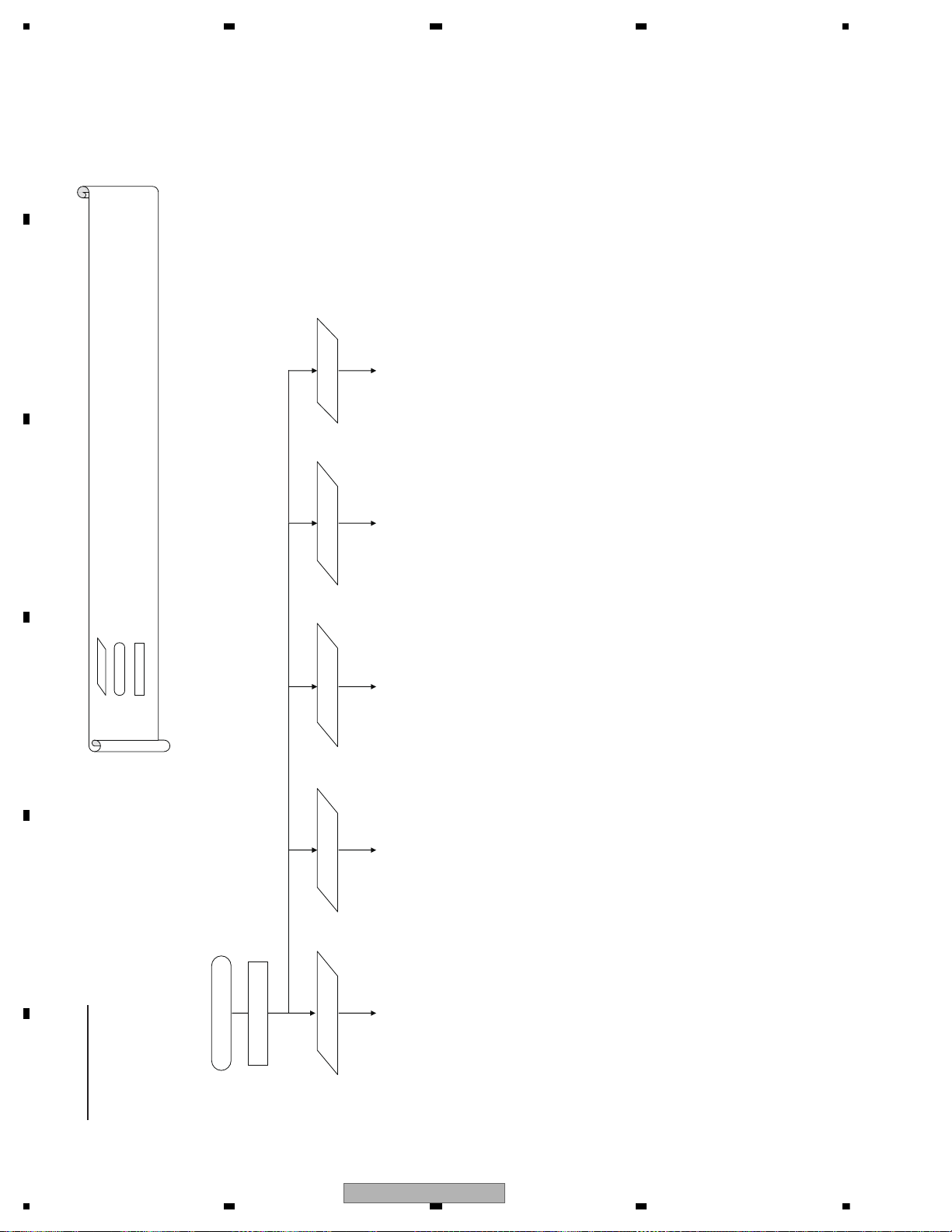
1234
1234
C
D
F
A
B
E
6. SERVICE MODE
[Note] The first four letters only. The rest of four letters are spaces
(5)(4)(3)(2)(1)
[Note] The DVD mecha needs to be activated in the test mode again to move to another test after selecting each test (FE/EDC1/EDC2).
Activate test mode
TEST
Select FE test Select EDC1 test Select EDC2 test
Continue to FE test mode image Continue to EDC1 test mode image Continue to EDC2 test mode image
Select LD live
time mode
Continue to LD live time mode image
Select simplified
FE test mode
Continue to simplified FE test mode
Test mode image
…Key operation
…Operation status
… Contents displayed by the DVD mecha (only those compatible with video)
Eight letters worth of the data is transmitted to the product (to the HOST side) through the UART communication
Legend:
[MUTE] + [FORWARD] + Reset start
Switch position of the remote control unit.
[AVH mode]
(1)-(8) and EJECT is the key of remote control unit.
6.1 DVD TEST MODE
66
AVH-P6300BT/XNUC
Page 67
5678
56
7
8
C
D
F
A
B
E
(8)(7)(6)(5)(3),(4)(2)(1)
Power_OFF
EJECT
1E00 0000
CRG_transfer to the
0300 0000
Disc type CD-RW
Disc type CD
outermost circumference
1D00 0000
CRG_HOME
Disc type
2 DVD layers
Eight letters worth of the data is transmitted to the product (to the HOST side) through the UART communication
… Operation status
… Contents displayed by the DVD mecha (only those compatible with video)
Legend: …Key operation
0000 0000 0100 0000 0200 0000
Disc type
1 DVD layer
LD-ON/OFF
CRG+/-
Measure S curve
LO-ON : 1100 0000
LD-OFF : 1000 0000
1C00 0000 : CRG-
1B00 0000 : CRG+
Operated while keys
are pressed down
1A00 0000
(2)
Stop F search
[Note] LD-OFF automatically occurs if no action is taken for approx. 10 seconds after LD-ON.
An error occurs if F close is attempted in the LD-OFF status.
Even during the focus search (S-shape measurement mode), failure of LD-OFF within 10 seconds violates
safety regulations. Therefore, LD-OFF occurs in 9 seconds despite focus search after LD-ON.
For F close after the focus search (S-shape measurement mode), power OFF first, then power ON again
Add two items: TEMAX level display / TEMIN level display
1100 0000
FEMAX level
FEMIN level
ASMAX level
ENVMAX level
FE normalization coefficient
Spindle gain coefficient
TEMAX level display
TEMIN level display
FE offset coefficient
TE offset coefficient
AS offset coefficient
ENV offset coefficient
TG offset coefficient
DBAL coefficient
VIN1 offset cancel value
VIN2 offset cancel value
VIN3 offset cancel value
VIN4 offset cancel value
VIN5 offset cancel value
VIN6 offset cancel value
VIN7 offset cancel value
VIN8 offset cancel value
VIN9 offset cancel value
VIN10 offset cancel value
FE test mode
0X00 0000
(1) EJECT(5)(4)(3)(2)
Power ON
0FFF 0000
Front-End test mode image
AVH-P6300BT/XNUC
1x00 0000
F close F search
a b
1FFF 0000
Focus closed status
67
Page 68
1234
1234
C
D
F
A
B
E
(2)
(1) (3),(4)(2) (8)
Delete GBAL coefficient.
For TBAL coefficient and TE normalization coefficient,
separate the display data identification in layer 0/layer 1.
(3),(4)(1) (6) (8)
For FBAL coefficient, focus gain coefficient,
tracking gain coefficient and AS normalization
adjustment value, separate the display data
identification in layer 0/layer 1.
* In the CRG +/- operation test, continue operation until the
NULL command is issued from the HOST
(8)(7)(2)(1)
(1)
For focus gain coefficient, tracking gain coefficient and
AS normalization adjustment value, separate the display
data identification in layer 0/layer 1.
To (2)
Tracking balance
TBAL coefficient (0 layer)
TBAL coefficient (1 layer)
TE normalization coefficient (0 layer)
TE normalization coefficient (1 layer)
Off-track adjustment result
Tracking close
Focus Jump
L0 layer : 2000 0000
L1 layer : 2100 0000
CRG+/-
Operated while keys
are pressed down
2B00 0000 : CRG+
2C00 0000 : CRG-
Power_OFF
CRG +/-
Power_OFF
Operated while keys
are pressed down
3B00 0000 : CRG+
3C00 0000 : CRG-
2x00 0000
2FFF 0000
3000 0000
3FFF 0000
FBAL coefficient (0 layer)
FBAL coefficient (1 layer)
Focus gain coefficient (0 layer)
Focus gain coefficient (1 layer)
Tracking gain coefficient (0 layer)
Tracking gain coefficient (1 layer)
AS normalization adjustment value (0 layer)
AS normalization adjustment value (1 layer)
Measure error ratio
Error ratio
Focus gain coefficient (0 layer)
Focus gain coefficient (1 layer)
Tracking gain coefficient (0 layer)
Tracking gain coefficient (1 layer)
AS normalization adjustment value (0 layer)
AS normalization adjustment value (1 layer)
T.OPEN
Power_OFF
RF level value
3FFF 0000
Tracking closed status
Start displaying
RF level value
5000 0000
Notify RF level once
every 500 msecs
End displaying RF
level value
a b
dc
68
AVH-P6300BT/XNUC
Page 69
5678
56
7
8
C
D
F
A
B
E
dc
(8)(7)(3),(4)(6)(5)(2)(1)
Power_OFF
To (2)
T.OPEN
E.g.) To specify 300000 for the ID, the specified ID is: 4A03 0000
For FBAL coefficient, focus gain coefficient,
tracking gain coefficient and AS normalization
adjustment value, separate the display data
identification in layer 0/layer 1.
AS normalization adjustment value (0 layer)
FBAL coefficient (0 layer)
FBAL coefficient (1 layer)
Focus gain coefficient (0 layer)
AS normalization adjustment value (1 layer)
Focus gain coefficient (1 layer)
Tracking gain coefficient (0 layer)
Tracking gain coefficient (1 layer)
T.Jump+/-
Jump+ : 4B00 0000
Jump- : 4C00 0000
ID Search
4A00 0000
Focus Jump
L0 layer : 4x00 0000
L1 layer : 4x00 0000
speed
Change playback
DVDX1.3~
(3)(1)-(4)
Specify No.
Specify ID
1.6CAV
4x00 0000
CDX4CLV:
(5)(5)
of tracks
of tracks
Start jumping
Display No.
To specify the number of tracks, select one from the prepared number of tracks.
Change to cyclic in (3). Determine in (4).
For CDs: 1, 4, 10, 11 or 32 tracks
For DVDs: 1, 4, 10, 11, 32, 64 or 100 tracks
Change how to specify an ID address.
Specify a digit with the commands (1) and (2). Commands (3) and (4) are to increase/decrease the
number. Determine with the command (5).
Display ID
Start searching
:4100 0000
:4300 0000
:4200 0000
:4000 0000
Three types of speed patterns only as shown above. The first two digits of the specified ID represent the test status. The rest of six digits are the ID.
DVD X CAV, CD X 2CLV
DVD X 1CLV, CD X 1CLV
L0 layer
L0 layer
:4000 0000
:4200 0000
changed
V
V
DVD X CAV
DVD X 1CLV
DVD X 1.3~1.6CAV, CD X 4CLV
DVD X 1CLV
L1 layer
L1 layer
L0 layer
L0 layer
Taking the Joy-Stick as an example, (1) = right, (2) = left, (3) = up, (4) = down and (5) = determine.
:4100 0000
:4300 0000
DVD X 1.3~1.6CAV
DVD X 1CLV
L1 layer
L1 layer
[Note] The equipment needs to be powered OFF and activated again in the test mode as no restoration is possible in case of an error in the Power_OFF.
4000 0000
Tracking closed status
4x00 0000
Measure
error ratio
Error ratio
Focus gain coefficient (0 layer)
Focus gain coefficient (1 layer)
Tracking gain coefficient (0 layer)
Tracking gain coefficient (1 layer)
AS normalization adjustment value (0 layer)
AS normalization adjustment value (1 layer)
AVH-P6300BT/XNUC
Error occurs
For focus gain coefficient, tracking gain
coefficient and AS normalization adjustment
value, separate the display data identification
in layer 0/layer 1.
(8)
Display error
Power_OFF
Display error
Error occurs in Power_OFF
69
Page 70
1234
1234
C
D
F
A
B
E
[Note] The same image is shared in EDC1 and EDC2.
(2)(1) [Note] Ejecting is allowed at any time during the EDC test mode,
provided that the BD disc status bit in the UART communication is uncertain
Eject
After completion of EJECT operation
(5)
[Note] Update the display at intervals of 0.5 seconds until 0/1 layer is selected or ejected.
(1)-(4)
EDC 1/2 test mode
0000 0000
Select 0 layer Select 1 layer
Specify ID
Start EDC 1/2
0000 0000 0100 0000
1003 0000 1103 0000
0 layer : 10** ****
1 layer : 11** ****
[Note] ** **** is the ID specified value
0 layer : 20** ****
1 layer : 21** ****
[Note] ** **** is the current ID value
EJECT operation
Test mode
Eject
**** ****
[Note] **** **** is the current ID value
EDC test mode image
Legend: …Key operation
… Operation status
… Contents displayed by the DVD mecha (only those compatible with video)
Eight letters worth of the data is transmitted to the product (to the HOST side) through the UART communication
70
AVH-P6300BT/XNUC
Page 71
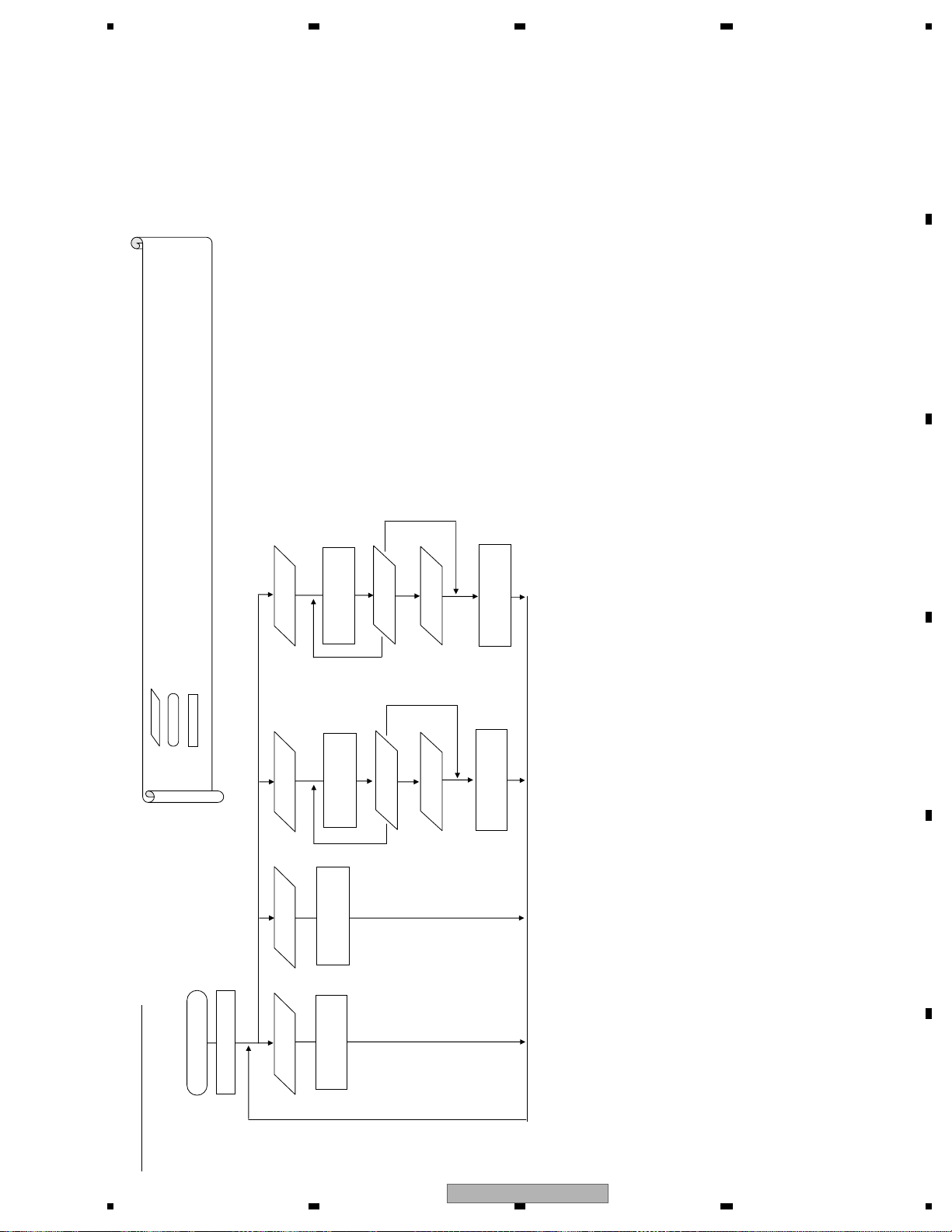
5678
56
7
8
C
D
F
A
B
E
(8)(8)
(6)(5)(2)(1)
live time
Set DVD LD
Eight letters worth of the data is transmitted to the product (to the HOST side) through the UART communication
… Operation status
… Contents displayed by the DVD mecha (only those compatible with video)
Legend: …Key operation
live time
Set CD LD
live time
Display DVD LD
set time
40** ****
30** ****
20** ****
[Note] ** **** represents
Specify the
(1)-(4)
set time
set time
set time
Specify the
(1)-(4)
[Note] ** **** is the
[Note] ** **** is the
DVD LD live time
(5)
(5)
Register the
set time
set time
Register the
20** ****
DVD LD live time
[Note] ** **** represents
10** ****
CD LD live time
[Note] ** **** represents
[How to specify a set time]
Specify a digit with the commands (1) and (2). Commands (3) and (4) are to increase/decrease the number. Determine with the command (5). Cancel with the command (8).
10** ****
0000 0000
LD live time mode
live time
Display CD LD
CD LD live time
[Note] ** **** represents
LD live time mode image
AVH-P6300BT/XNUC
[Note] All live times exceeding 999999 hours are notified as 999999 hours.
[Note] The live time represented in “*E** ****” may not be an accurate
value as it represents the end of the life of the FLASH memory.
71
Page 72
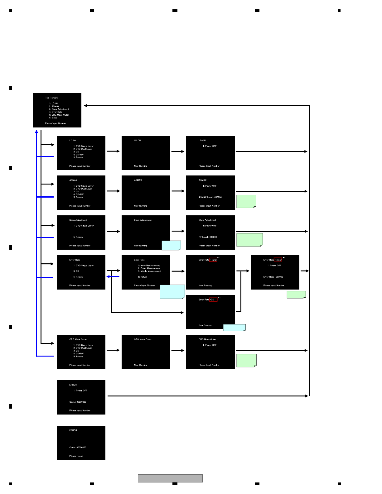
1234
1234
C
D
F
A
B
E
2 Select
3 Select
4 Select
Select
Select
Select DVD
Select
Select CD
5 Select
Return
5 Select
Return
5 Select
Return
5 Select
Return
5 Select
Select
5 Select
Return
1 Select
Select
5 Select
Return
LD ON
completed
Acquire
ASMAX
value
Acquire RF
level value
Select
Select
Select
Display ASMAX
value
Display RF level
value
(Updated at intervals
of approx. 500 msecs)
Select
Acquire error
ratio
Search
destination ID
0x00100000
Search destination ID
Inner : 0x00040000
Outer : 0x00200000
Middle : 0x00100000
Search destination
CRG home position
*1: Display the selected position
Inner DVD: Inner
Outer DVD: Outer
Middle DVD: Middle
CD: CD
Select
Display error ratio
CRG Move
completed
<In case of an error>
<In case of an error in Power_OFF>
Select
CRG transfers to
the outermost
circumference
<Screen transition>
Simplified FE test mode
Numbers on each screen can be selected with the “test key commands”.
No display data for the test mode is notified in the simplified FE test mode.
[Notes]
The simplified FE test mode checks the status transition and the test results only with the mecha OSD. Therefore, the following actions need to be taken in the HOST:
• Output the mecha image output to the front monitor. To locate the operating buttons on the screen, combine the screen display and button operation.
• In case of the product with the rear monitor output, output the image of the simplified test mode.
For these actions, consult with the service department.
72
AVH-P6300BT/XNUC
Page 73
5678
56
7
8
C
D
F
A
B
E
Service Test Mode
The service test mode is used to check functions in fault diagnosis by a serviceman in case of any defect found in the
DVD mecha.
This mode is enabled only when the test mode is activated. At this time, no normal operation is executed.
1. Outline
The service test mode is used to check functions in fault diagnosis by a serviceman in case of any defect found in the
DVD mecha. No general user goes into this mode.
The mode is implemented mainly to check the FE part. It is originally the test mode at the FE part implemented in the
PC communication, which is modified to allow implementation in the HOST communication.
The command for the test mode received in the HOST communication is interpreted by the application part, converted
to the PC communication command and transferred to the OS.
The OS transfers this command to the PC task as if it received the command in the PC communication.
The execution result is noticed to the application part by an e-mail instead of the PC communication.
The application part then transmits the result in the HOST communication to display OSD.
2. Conditions for operation
(1) This service test mode is enabled only when the test mode is activated. At this time, no normal operation is executed.
(2) No request from the host is received while the core executes the test mode command.
(3) The core start-up notice is not necessary in the test mode.
3. Requests for HOST
The service test mode requires two items: the item that displays the notice command in the FE test mode in HOST
and the item to display the mecha OSD with no change in the simplified FE test mode.
Displaying the test result only in the mecha OSD, the simplified FE test mode does not require the notice of the test
result to HOST.
Therefore, the simplified FE test mode needs to display the video output of the mecha on the monitor.
4. I/F specifications
5. Operation flow
STATUS = 00h, TP = 11h, D0 = EEh, (Key commands for the test mode)
D1: Types of key commands exclusive for the test mode
* In CRG+/-, operation stops when the key is released. At that time, the DVD mecha should make the
key command request (TP = B1h) on a regular basis to prevent any omission of key release.
Specification for the UART (HOST) communication
1) Key commands for the test mode
Value of D1 Purpose
01h Test mode command (1)
02h Test mode command (2)
03h Test mode command (3)
04h Test mode command (4)
05h Test mode command (5)
06h Test mode command (6)
07h Test mode command (7)
08h Test mode command (8)
D0h Test mode command EJECT
F0h Test mode command NULL
AVH-P6300BT/XNUC
73
Page 74
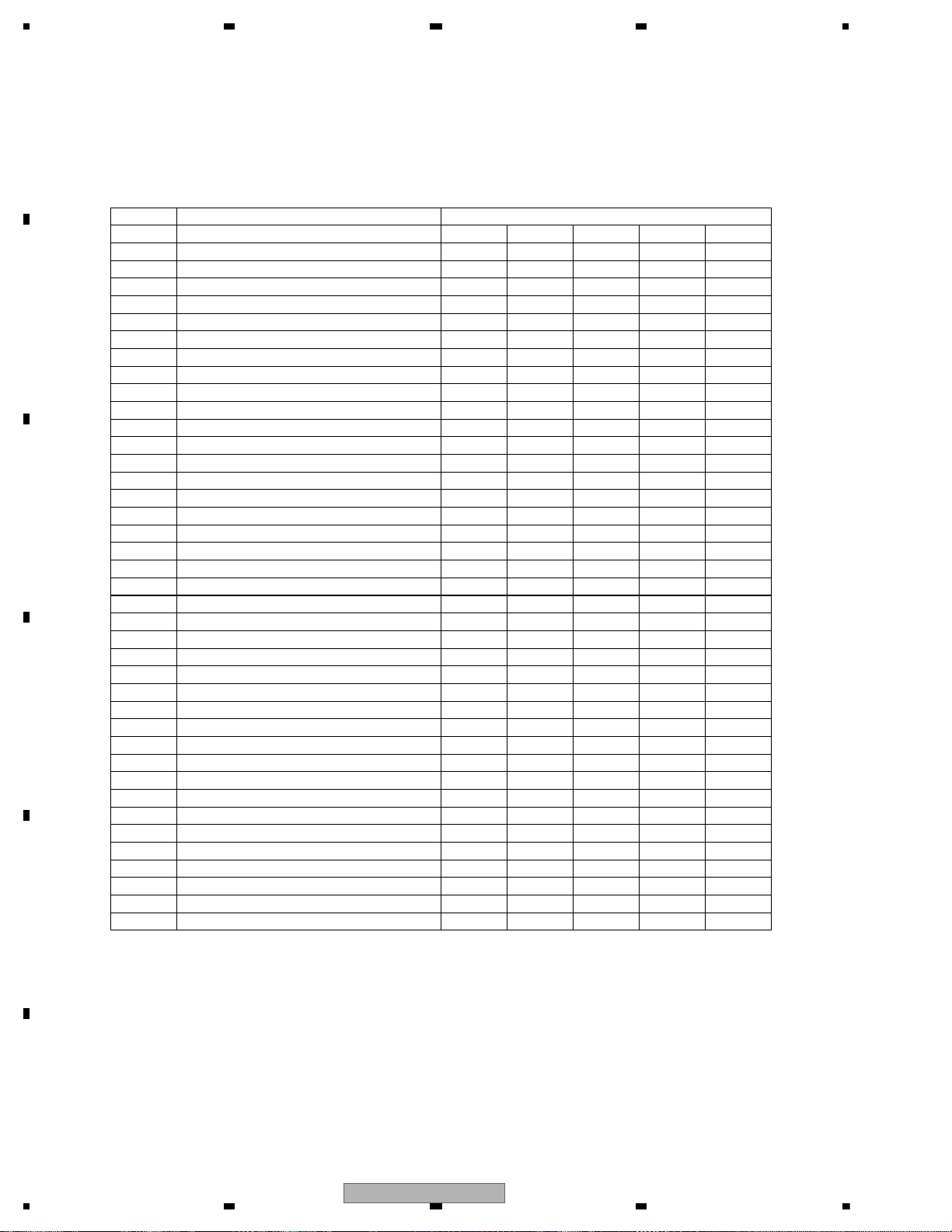
1234
1234
C
D
F
A
B
E
STATUS = 00h, TP = B5h, D0 = 02h, (Display data for the test mode)
D1: Display data identifier exclusive for the test mode
[The values of D1 are as shown in the table below]
D2 – 9: Eight letters worth of display data in ASCII. (Status or results are displayed)
* Each coefficient (excluding the status display) outputs data at intervals of every second.
E.g.) Power-on (examples of “1-” in the continuous display specifications above)
D1 = 01h, set the status display data to D2 – D9 and transmit
[1 second later]
D1 = 02h, set the FE offset coefficient to D2 – D9 and transmit
[1 second later]
D1 = 03h, set the TE offset coefficient to D2 – D9 and transmit
:
:
[1 second later]
D1 = 07h, set the DBAL coefficient to D2 – D9 and transmit
[1 second later]
D1 = 01h, after setting the status display data to D2 – D9 and transmitting, wait for keys
2) Display data for the test mode
Value of D1
Purpose Continuous display specification
01h Status display
02h FE offset coefficient 1-1
03h TE offset coefficient 1-2
04h AS offset coefficient 1-3
05h ENV offset coefficient 1-4
06h TG offset coefficient 1-5
07h DBAL coefficient 1-6
30h VIN1 offset cancel value 1-7
31h VIN2 offset cancel value 1-8
32h VIN3 offset cancel value 1-9
33h VIN4 offset cancel value 1-10
34h VIN5 offset cancel value 1-11
35h VIN6 offset cancel value 1-12
36h VIN7 offset cancel value 1-13
37h VIN8 offset cancel value 1-14
38h VIN9 offset cancel value 1-15
39h VIN10 offset cancel value 1-16
08h FEMAX level 2-1
09h FEMIN level 2-2
0Ah ASMAX level 2-3
0Bh ENVMAX level 2-4
0Ch FE normalization coefficient 2-5
0Dh Spindle gain coefficient 2-6
0Eh TBAL coefficient (0 layer) 3-1
1Eh TBAL coefficient (1 layer) 3-2
10h TE normalization coefficient (0 layer) 3-3
20h TE normalization coefficient (1 layer) 3-4
40h Off-track adjustment result 3-5
11h FBAL coefficient (0 layer) 4-1
21h FBAL coefficient (1 layer) 4-2
12h Focus gain coefficient (0 layer) 4-3 5-2
22h Focus gain coefficient (1 layer) 4-4 5-3
13h Tracking gain coefficient (0 layer) 4-5 5-4
23h Tracking gain coefficient (1 layer) 4-6 5-5
14h
AS normalization adjustment value (0 layer)
4-7 5-6
24h
AS normalization adjustment value (1 layer)
4-8 5-7
15h Error ratio 5-1
16h TEMAX level 2-7
17h TEMIN level 2-8
50h RF level
74
AVH-P6300BT/XNUC
Page 75
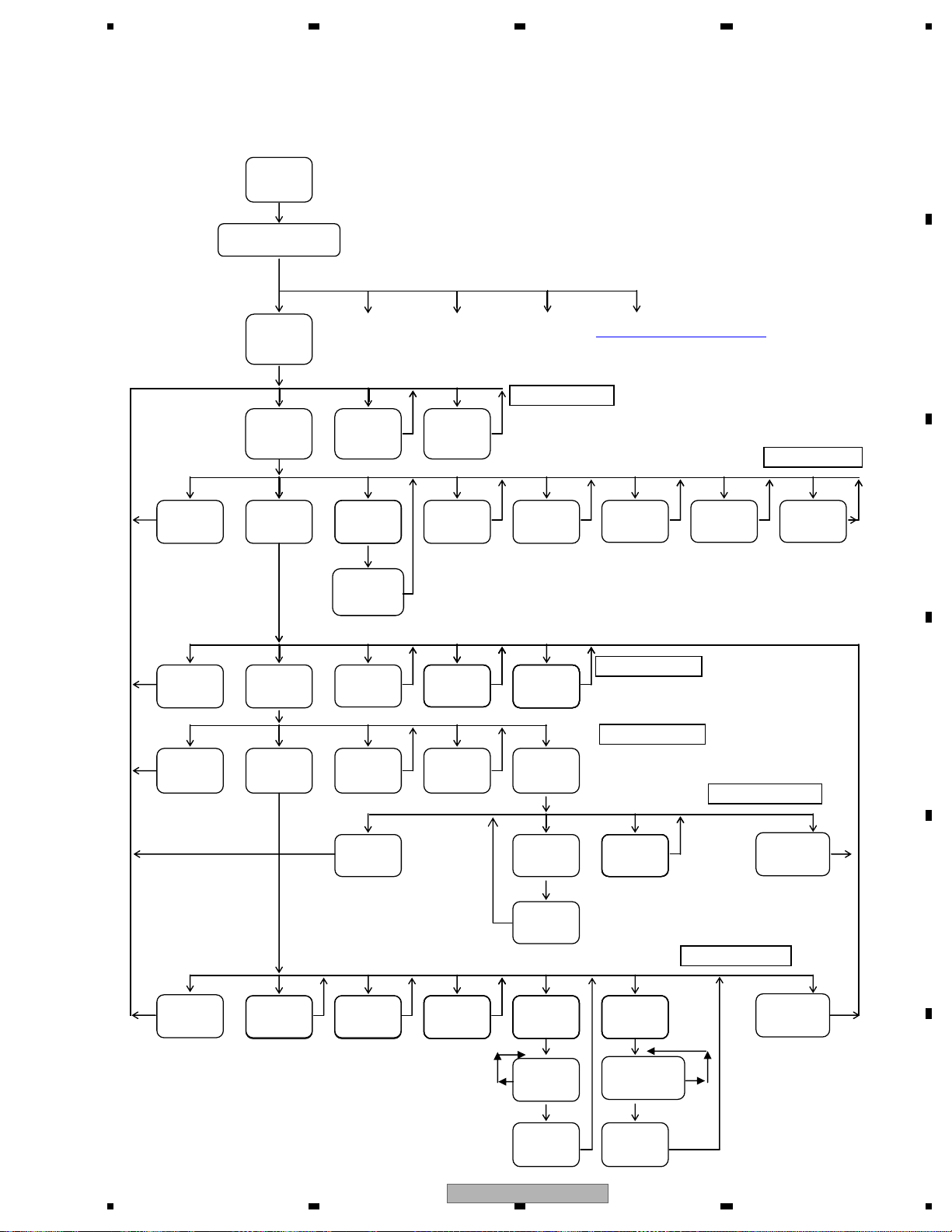
5678
56
7
8
C
D
F
A
B
E
Note 1
A media type is specified here. Settings should be implemented according to this specification.
Note 2 Switching gains should be: normal gain -> OEIC =H -> OEIC =H and FEPx4 amps ON
Note 3 Any other operation is prohibited during measurement
Note 4 Playback speed should be: 1.3 – 1.6CAV for DVDs and x4CLV fixed for CDs
Number of keys required for the product: nine ((1) – (8) plus EJECT)
Test Mode In Activate the test mode
Set the source to DVD
The test mode commands 1 to 8 + EJECT as well as the NULL command should be used for the
HOST communication.
To specify the number of tracks, select one from the prepared numbers of tracks.
Change to cyclic in (3). Determine in (4).
For CDs: 1, 4, 10, 11 or 32 tracks
For DVDs: 1, 4, 10, 11, 32, 64 or 100 tracks
Change how to specify an ID address
Specify a digit with the commands (1) and (2). Commands (3) and (4) are to increase/decrease
the number. Determine with the command (5).
Taking the Joy-Stick as an example, (1) = right, (2) = left, (3) = up, (4) = down and (5) = determine.
*F close and F search will not be executed unless LD is ON.
(1) (2) (3) (4) (5)
To FE
* To 1 * To 2 * To 3
* To simplified FE test mode
test mode
(1) (2)-(5) EJECT Powered OFF status
(2):1 DVD layer
(3):2 DVD layers
Disc TypePower On Eject (4):CD
Note 1
(5):CD-RW
Powered ON status
(8) (1) (2) (3) (4) (5) (6) (7)
Power Off
Focus Close
Adjustment
included
Focus Search
CRG+
CRG- CRG_HOMELD_ON
Carriage transferred
to the outermost
circumference
(2)
Focus Search
STOP
(8) (1) (2) (3) (4)
T.Bal
Other adjustment
Focus JumpPower Off CRG-
CRG+
Focus Close status 1
included
(8) (1) (3) (4) (5) Focus Close status 2
Tracking Close
Adjustment
included
CRG+Power Off
CRG-
RF level value
RF level display status
(8) (1) (2) (7)
Power Off
(8) (1) (2) (5) (6) (3),(4) (7)
Power Off
Measure
error ratio
Note 3
Switch playback
speed
Note 4
AVH-P6300BT/XNUC
Start displaying
RF level value
Measure
error ratio
Note 3
Tracking Open
(1)
End displaying
RF level value
Tracking Close status
ID Search T.JumpFocus Jump Tracking Open
+/-
(1)-(4) (3)
Specify ID
Specify No.
of tracks
(5) (5)
Start ID search
Start jumping
75
Page 76
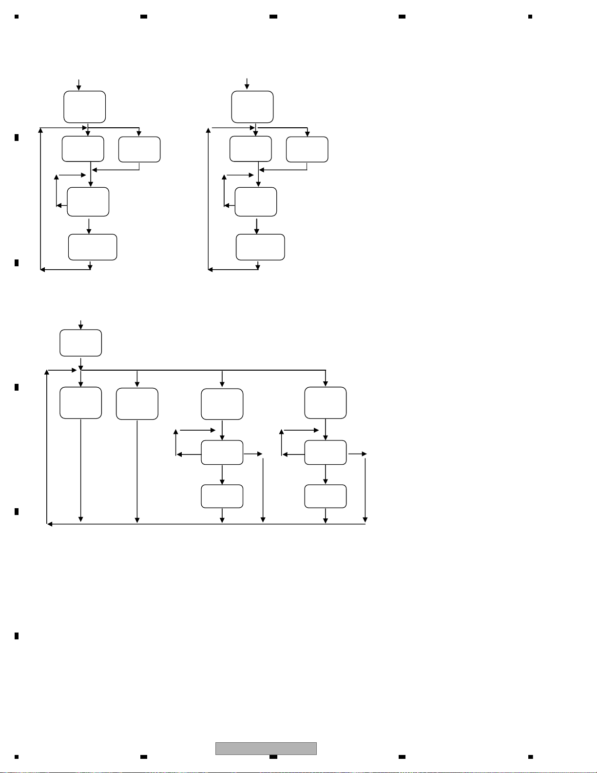
1234
1234
C
D
F
A
B
E
*1 *2
EDC2
mode
(1) (2) (1) (2)
Select
0 layer
Select
1 layer
Select
0 layer
Select
1 layer
(1)-(4) (1)-(4)
Specify ID Specify ID
(5) (5)
Start EDC1 Start EDC2
*3
LD live time
mode
(1) (2) (5) (6)
Display CD
LD live time
Display DVD
LD live time
Set CD LD
live time
Set DVD LD
live time
Specify
set time
Specify
set time
Register
set time
Register
set time
EDC1
mode
(1)-(4) (1)-(4)
(5)(5)
(8)(8)
[How to specify a set time]
Specify a digit with the commands (1) and (2). Commands (3) and (4) are to increase/decrease the number. Determine with the command (5).
Cancel with the command (8).
76
AVH-P6300BT/XNUC
Page 77
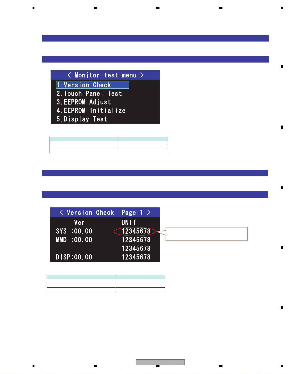
5678
56
7
8
C
D
F
A
B
E
[Method for Mode IN]
When the reset start is done while pushing REVERSE and EJECT, it shifts to the monitor test mode.
[Display specifications]
[Method for Mode IN]
Choose "Version Check" among the monitor test mode menu screen.
[Display specifications]
[Operation specification]
Operational description Remote controller key
Selection cursor up movement 2
Selection cursor down movement 8
Menu enter 5
1. Version Check
[Operation specification]
Operational description Remote controller key
Return to test mode menu 1
Page up
9
Page down
7
When 8 digits of read number is strange,
displayed with red.
6.2 MONITOR TEST MODE
AVH-P6300BT/XNUC
77
Page 78
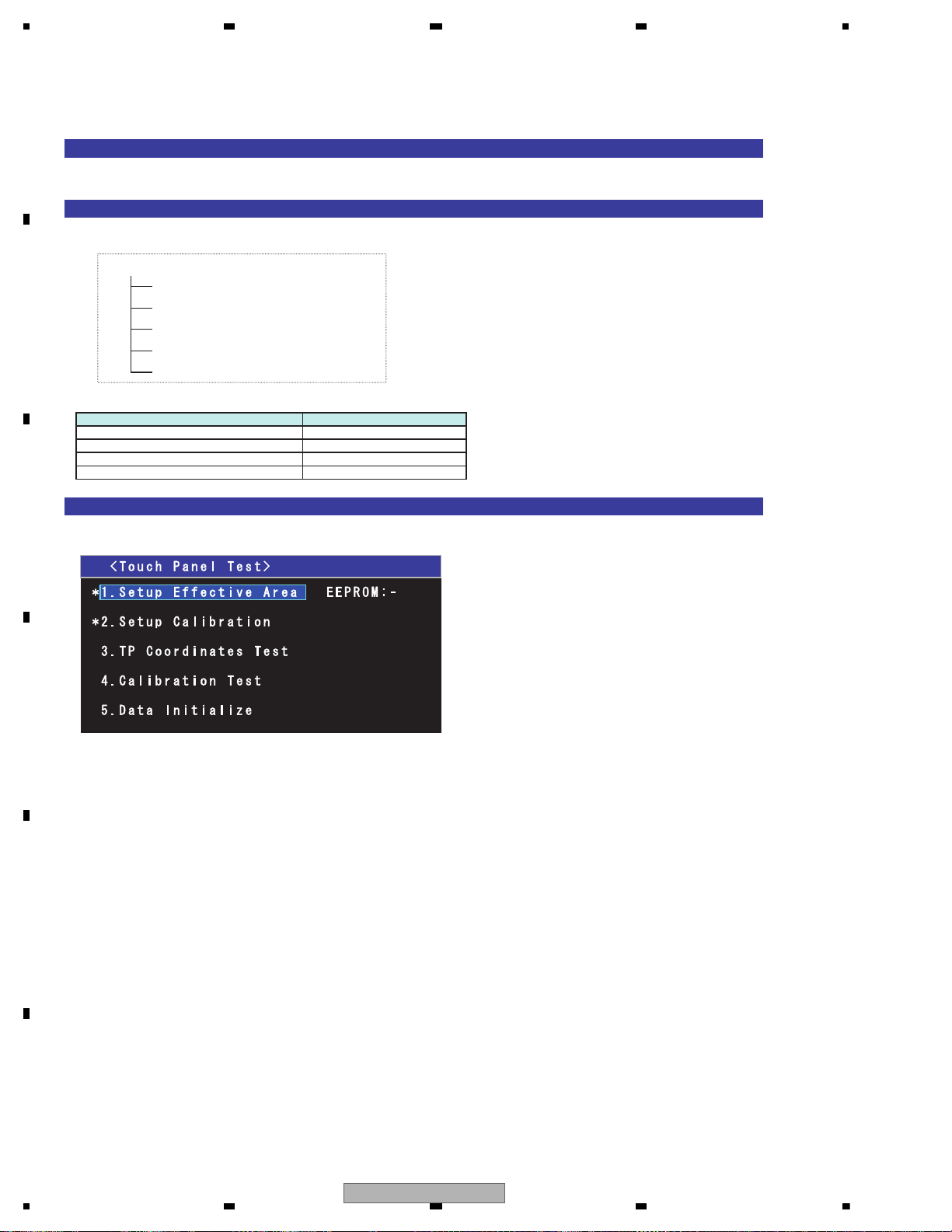
1234
1234
C
D
F
A
B
E
[How to activate the touch panel test mode]
Choose "Touch Panel Test" among the monitor test mode menu screen.
[Menu types in the mode]
The calibration test mode consists of the following menus.
Top menu
[Description of the top menu]
[Display specification]
Conditions for lighting of the adjustment complete mark “ * ”.
Outermost circumference inspection :
In case the outermost circumference inspection has been completed normally.
Calibration inspection :
In case the calibration has been completed normally.
Conditions for the adjustment complete mark “ * ” to go out.
Outermost circumference inspection :
In case the outermost circumference inspection has never been performed.
In case the EEPROM initialization has been performed.
In case the adjustment value has been initialized.
Calibration inspection :
In case the calibration inspection has never been performed.
In case the EEPROM initialization has been performed.
In case the adjustment value has been initialized.
Data initialization
Outermost circumference inspection
Calibration inspection
Coordinate inspection
Calibration verification
[Operation specification]
Operational description Remote controller key
Selection cursor up movement 2
Selection cursor down movement 8
Return to test mode menu 1
Menu enter 5
2. T ouch Panel T est
78
AVH-P6300BT/XNUC
Page 79
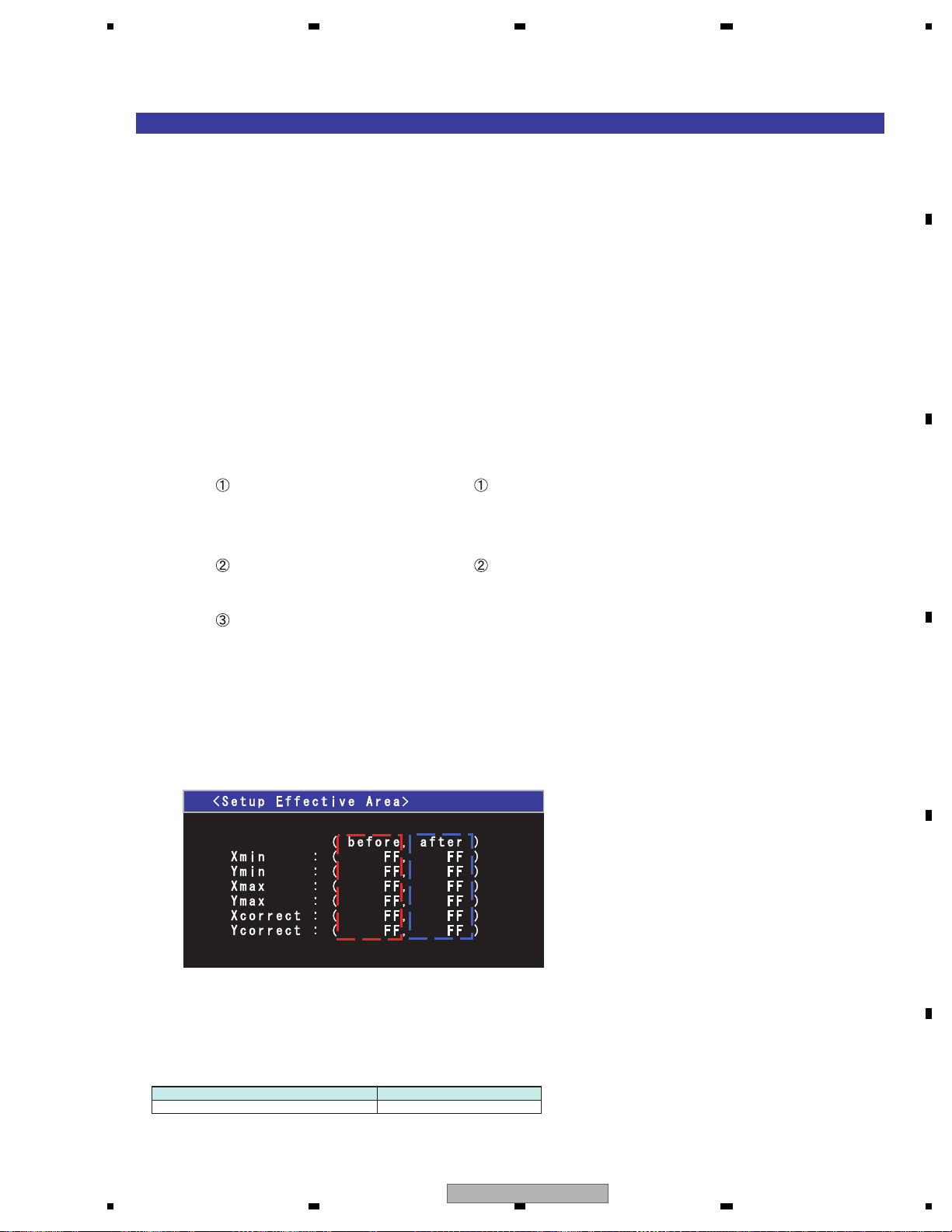
5678
56
7
8
C
D
F
A
B
E
[Outermost circumference inspection]
[Outline]
Outermost circumference value of X and Y is obtained by tracing the outermost circumference of
the touch panel screen.
When exiting the menu screen by pressing 5 key, the captured value is stored in the EEPROM.
Furthermore, when storing the value, checking is made as to whether the value is within the range or not.
When the value is within the range.
Write the following value and adjustment information to the EEPROM, then “OK” is displayed.
1. The outermost value of X and Y(min/max) : 4 byte
2. The reference value for A/D correction of X,Y : 2 byte
3. Adjustment information(Adjustment OK) : 1 byte
When the value is within the range.
Write the following adjustment information to the EEPROM, then “NG” is displayed.
1. Adjustment information(Adjustment NG) : 1 byte
The initial value and the setting value allowable range are as follows.
<Before initial value> <After initial value>
Outermost value Outermost value
Xmin : 3Bh Xmin : 78h
Ymin : 43h Ymin : 78h
Xmax : F6h Xmax : B4h
Ymax : EEh Ymax : B4h
A/D correction value A/D correction value
X : 35h X : 00h
Y : 39h Y : 00h
Setting value allowable range
X direction Minimum value : 00h to 80h
Maximum value : 9Eh to FFh
Maximum value - Minimum value : more then 73h
Y direction Minimum value : 00h to 83h
Maximum value : 9Ah to FFh
Maximum value - Minimum value : more then 6Bh
[Display specifications]
Outermost circumference inspection in process
X/Y information of [MIN] and [MAX] of the outermost circumference are displayed.
[BEFOR] indicates the value stored in the EEPROM.
[AFTER] indicates MIN/MAX of the A/D value currently captured.
[Operation specification]
Operational description Remote controller key
Return to top menu 5
AVH-P6300BT/XNUC
79
Page 80
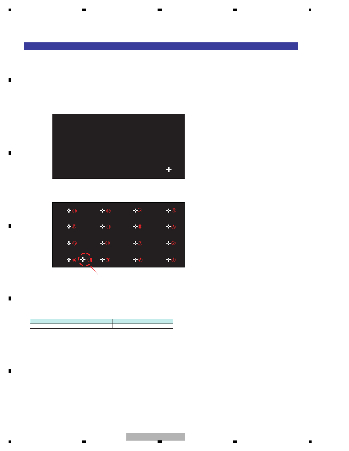
1234
1234
C
D
F
A
B
E
[16 points adjustment]
[Outline]
When correctly touched, the cursor will disappear, and the next cursor will appear. Calibration is conducted
by repeating this process 16 times.
When the 17th point has been finally touched, setting information for the 16 points and the normal ending
information, total of 17 byte data, are written into the EEPROM, and the screen returns to the TOP menu.
[Display specifications]
16 points adjustment in process
Order of display of the locations to be pressed.
This point is intended to end the
calibration inspection, and therefore, the
corrected value of this point is not obtained.
[Operation specification]
Operational description Remote controller key
Return to top menu 5
80
AVH-P6300BT/XNUC
Page 81
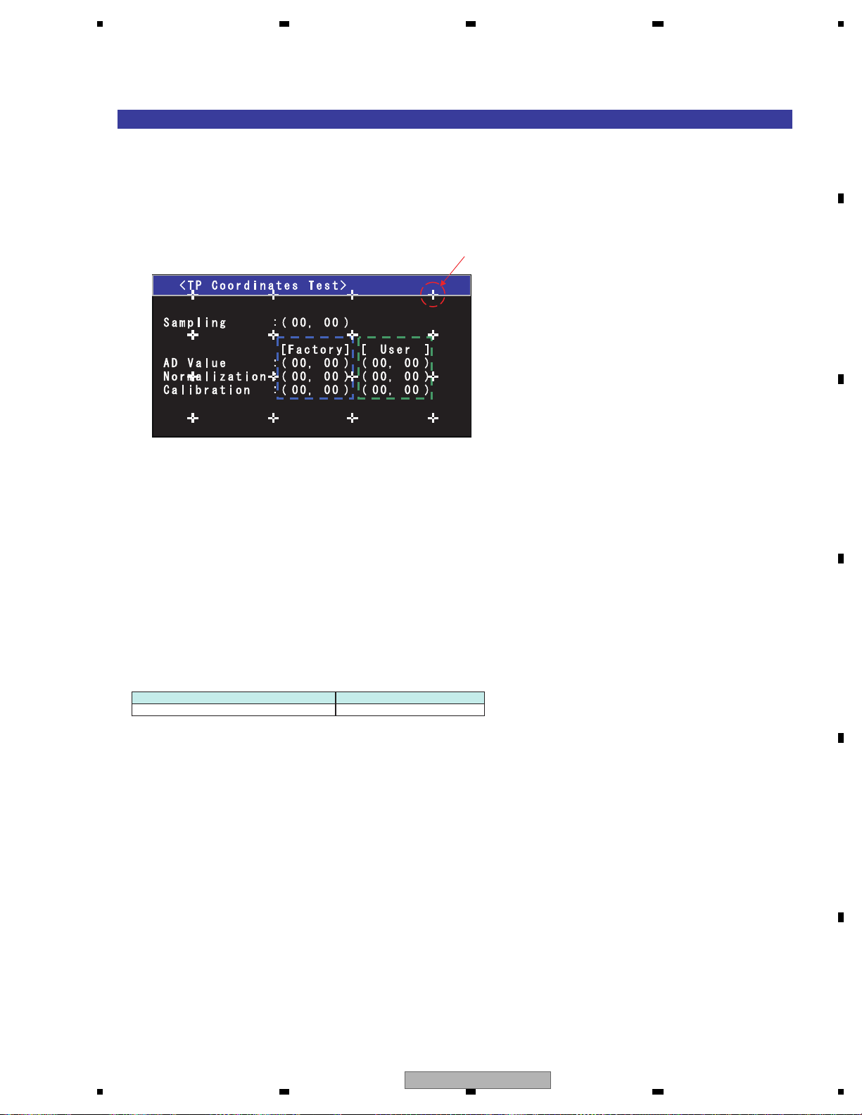
5678
56
7
8
C
D
F
A
B
E
[Coordinate inspection]
[Outline]
The coordinate before correction and after correction at the time of pressing the touch panel are displayed for
coordinate verification.
Furthermore, the red "+" cursor can be moved by the key operaiont mentioned bellow, and the coordinate of
the cursor center is displayed.
[Display specifications]
Fixed display
[Operation specification]
Operational description Remote controller key
Return to top menu 1
Each displayed coordinate is as follows.
The values under [Factory] are the corrected values in the Factory region and the values under [User] are
the corrected values in the User region.
• Sampling : A/D value (X direction, Y direction) of the pressed point is displayed.
• AD Value : The coordinate (X direction, Y direction) of the A/D value of the pressed point corrected by
the reference value for A/D correction is displayed.
• Normalization : The coordinate (X direction, Y direction) after normalizing the A/D corrected coordinate
within the effective range is displayed. (0~255)
• Calibration : The coordinate (X direction, Y direction) which is the result of adding the correction
by calibration to the normalized coordinate is displayed.
16 calibration points "+" are displayed in white.
AVH-P6300BT/XNUC
81
Page 82

1234
1234
C
D
F
A
B
E
[Calibration verification]
[Outline]
Touch the cursor “+” displayed on the screen. The correct touch will delete the cursor and another cursor
will be displayed. The incorrect touch will make the characters of cursor turn red.
Repeat this for 4 points, and “OK” is displayed upon the last press of 4th point.
[Display specifications]
The pushing order
confirming
[Operation specification]
Operational description Remote controller key
Return to top menu 1
82
AVH-P6300BT/XNUC
Page 83
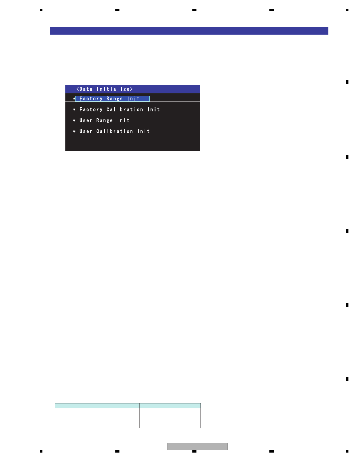
5678
56
7
8
C
D
F
A
B
E
[Data initialization]
[Outline]
Result of outermost circumference inspection and of calibration inspection (corrected value) are returned to
their initial values.
As for the initialized items, the initial values are written into the EEPROM and the adjustment information
is cleared.
[Display specifications]
Conditions for the adjustment completion mark (*) to be lighted up.
Outermost circumference inspection
When the outermost circumference inspection of the calibration for line has been completed normally.
Calibration inspection
When the calibration inspection of the calibration for line has been completed normally.
User outermost circumference inspection
When the user outermost circumference inspection of the calibration for line has been completed normally.
User calibration inspection
When the user calibration inspection of the calibration for line has been completed normally.
Conditions for the adjustment completion mark (*) to go out.
Outermost circumference inspection
When the above mentioned lighting conditions are not applicable.
When the adjusted value has been initialized (Data initialize).
When the EEPROM has been initialized.
Calibration inspection
When the above mentioned lighting conditions are not applicable.
When the adjusted value has been initialized (Data initialize).
When the EEPROM has been initialized.
User outermost circumference inspection
When the above mentioned lighting conditions are not applicable.
In case the outermost circumference inspection of the calibration for line or the 16-point adjustment is normally
terminated after normal termination of the outermost circumference inspection for user calibration.
When the adjusted value has been initialized (Data initialize).
When the EEPROM has been initialized.
User calibration inspection
When the above mentioned lighting conditions are not applicable.
In case the outermost circumference inspection of the calibration for line or the 16-point adjustment is normally
terminated after normal termination of the outermost circumference inspection for user calibration.
When the adjusted value has been initialized (Data initialize).
When the EEPROM has been initialized.
[Operation specification]
Operational description Remote controller key
Selection cursor up movement 2
Selection cursor down movement 8
Menu enter 5
Return to test mode menu 1
AVH-P6300BT/XNUC
83
Page 84
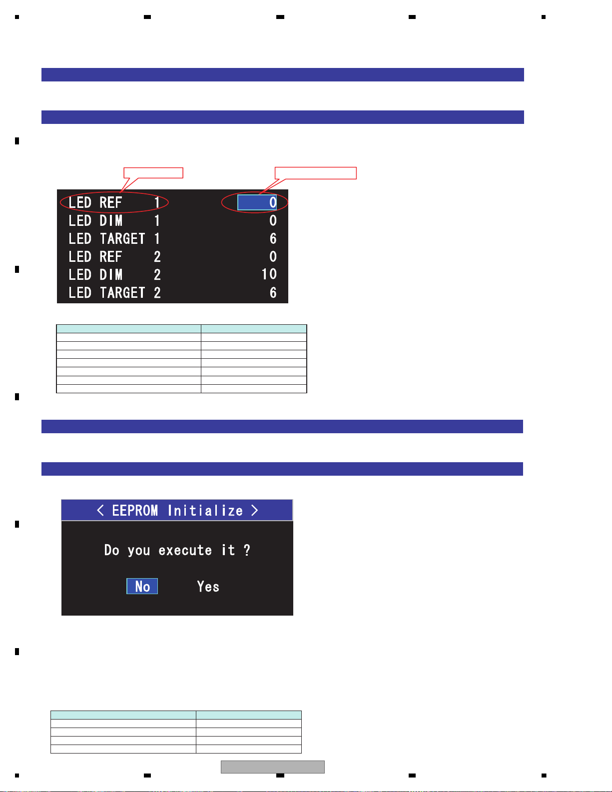
1234
1234
C
D
F
A
B
E
[Method for Mode IN]
Choose "EEPROM Adjust" among the monitor test mode menu screen.
[Display specifications]
3. EEPROM Adjust
example)
Adjustment value
Setting item
[Operation specification]
Operational description Remote controller key
Selection cursor up movement 2
Selection cursor down movement 8
Item content value up 6
Item content value down 4
Next menu page 9
Former menu page 7
Return to test mode menu 1
[Method for Mode IN]
Choose "EEPROM Initialize" among the monitor test mode menu screen.
[Display specifications]
Default of a cursor is the location of "No".
Choose "YES" and decide, initialize a setting value.
*) Don't turn off power while initializing.
When normally ends, "It succeeded" is displayed.
When will not end in four seconds, judged to be abnormal, "It failed" is displayed.
[Operation specification]
Operational description Remote controller key
Selection cursor left movement 4
Selection cursor right movement 6
Return to test mode menu 1
Menu enter 5
4. EEPROM Initialize
The setting items and the adjusted values are displayed on each page.
*The adjusted value section indicates initial values stored in EEPROM.
*If writing a value fails, the indication will not change.
When EEPROM is initialized, eject lock may be enabled. Please cancel eject lock in this case.
84
AVH-P6300BT/XNUC
Page 85
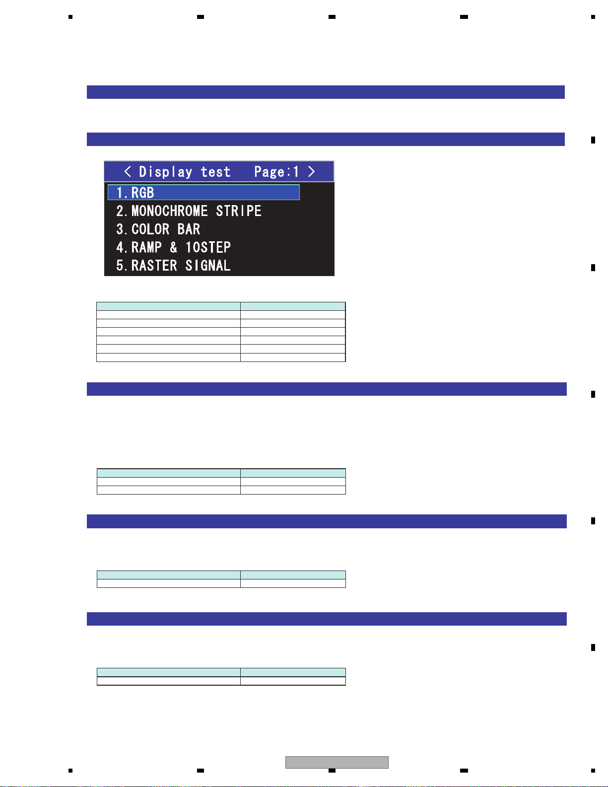
5678
56
7
8
C
D
F
A
B
E
[Method for Mode IN]
Choose "Display Test" among the monitor test mode menu screen.
[Display specifications]
5. Display Test
[Operation specification]
Operational description Remote controller key
Selection cursor up movement 2
Selection cursor down movement 8
Page up 9
Page down 7
Menu enter 5
Return to test mode menu 1
[RGB]
RGB is plotted in the following pattern:
R100% -> R50% -> G100% -> G50% -> B100% -> B50% -> BLACK -> GRAY -> WHITE -> GREEN and MAGENTA
dot signal
(The display of the screen will be changed in 1 second.)
[Operation specification]
Operational description Remote controller key
Stop/Restart 5
Return to test mode menu 1
[MONOCHROME STRIPE]
Display of monochrome stripe signal (1dot Width)
[Operation specification]
Operational description Remote controller key
Return to test mode menu 1
[COLOR BAR]
Display of color bar signal
[Operation specification]
Operational description Remote controller key
Return to test mode menu 1
AVH-P6300BT/XNUC
85
Page 86
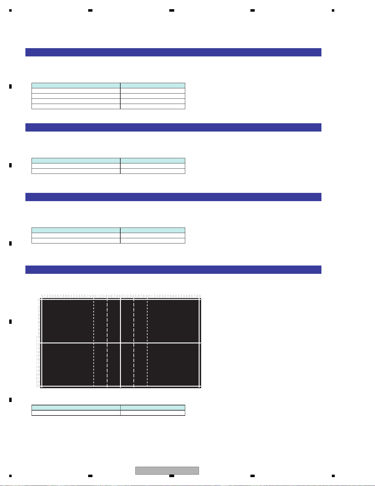
1234
1234
C
D
F
A
B
E
[RAMP & 10STEP]
Display of step signal and signal for alpha blend check
[Operation specification]
Operational description Remote controller key
alpha blend rate up 2
alpha blend rate down 8
Next signal 5
Return to test mode menu 1
[RASTER SIGNAL]
Display of signal for step confirmation
[Operation specification]
Operational description Remote controller key
Next signal 5
Return to test mode menu 1
[CONTRAST]
Display of Black/White signal
[Operation specification]
Operational description Remote controller key
Next signal 5
Return to test mode menu 1
[CENTER MARKER]
Display of signal for screen central location setting.
[Operation specification]
Operational description Remote controller key
Return to test mode menu 1
86
AVH-P6300BT/XNUC
Page 87
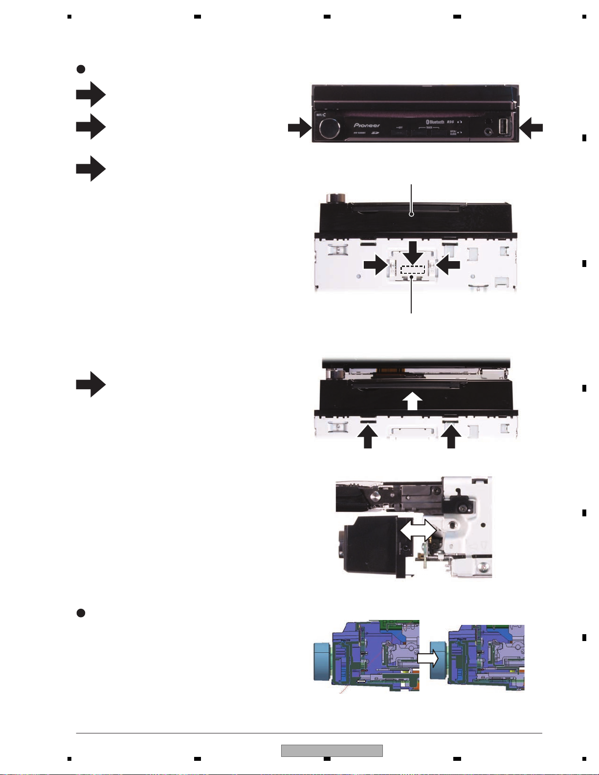
5678
56
7
8
C
D
F
A
B
E
Remove the two screws.
Remove the two screws and then remove
the Holder.
Disconnect the connector.
1
4
2
3
1
2
1
4 4
3
Grille Assy
Holder
Removing the Grille Assy (Fig.1)
Fig.1
Slide the Grille Assy forward by pushing two
tabs with tweezers or other item.
Attach and remove the Grille Assy by
sliding it horizontally.
2
How to assemble the Grille Assy
As the mother PCB SD part is fixed with
the Grille Assy, insert it horizontally.
7. DISASSEMBLY
AVH-P6300BT/XNUC
87
Page 88
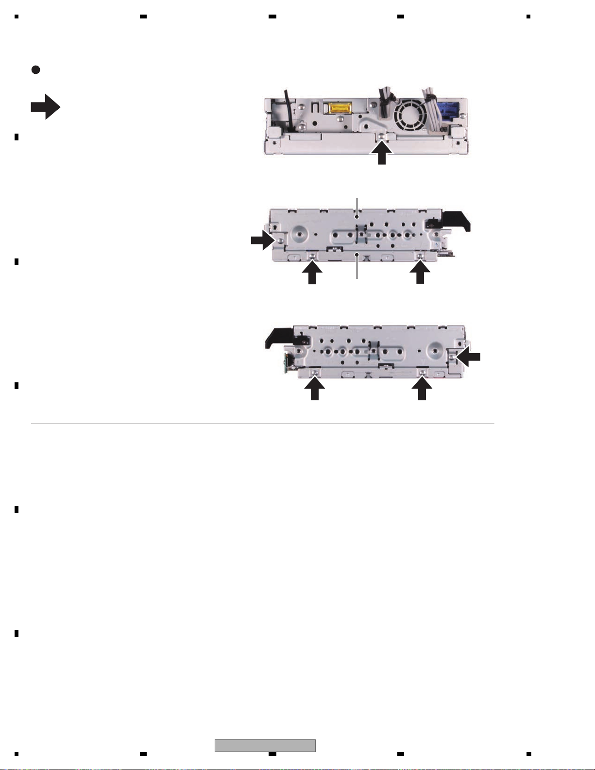
1234
1234
C
D
F
A
B
E
Remove the seven screws and then separate the Drive Unit and the Chassis Assy.
1
1
1
1
1
1
1 1
Chassis Assy
Drive Unit(Left Side)
(Rear Side)
(Right Side)
How to separate the Drive Unit and the
Chassis Assy (Fig. 2)
Fig.2
88
AVH-P6300BT/XNUC
Page 89
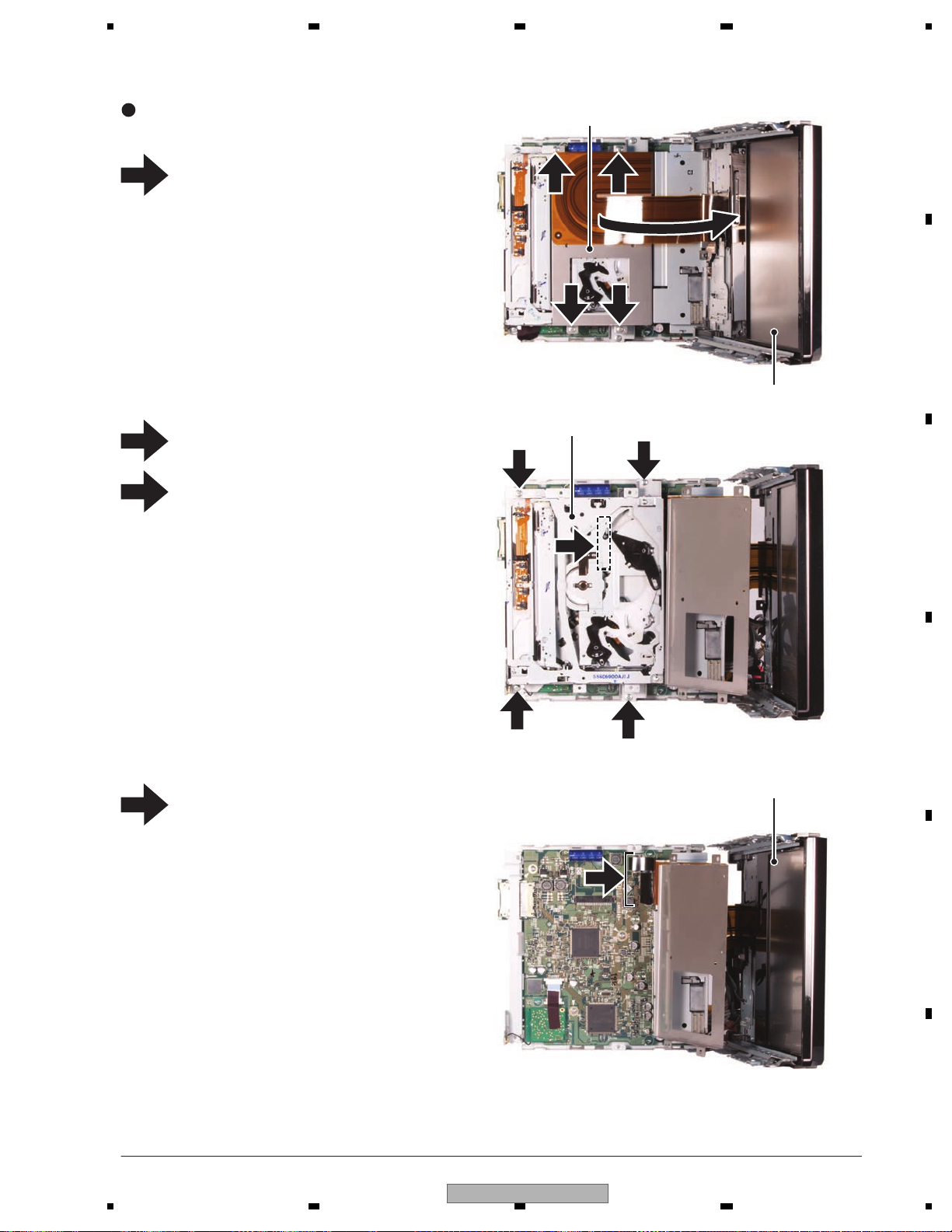
5678
56
7
8
C
D
F
A
B
E
Fig.3
1
2
1
2
1 1
2
2
Remove the four screws and then lift the
Bracket toward the Drive Unit.
Remove the four screws.
Disconnect the connector and then remove
the DVD Mechanism Module.
Disconnect the two connectors and then
remove the Drive Unit.
1
2
3
4
Removing the DVD Mechanism Module
and the Drive Unit (Fig.3)
Bracket
DVD Mechanism Module
Drive Unit
Drive Unit
3
4
AVH-P6300BT/XNUC
89
Page 90
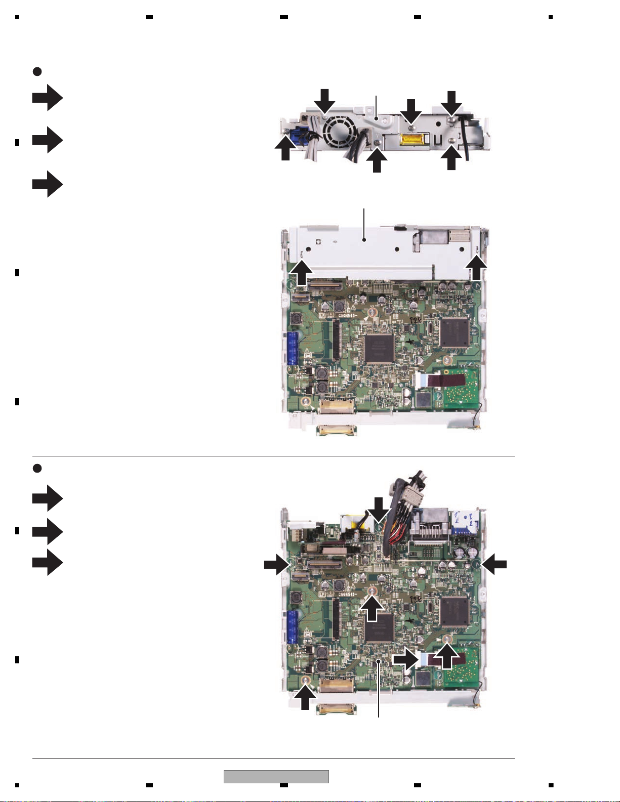
1234
1234
C
D
F
A
B
E
3
2
3
1
1
1
Fig.5
Fig.4
2
1
2
3
3
3
2
2
2
Remove the screw.
Remove five screws.
Straighten the tabs at two locations indicated
and then remove the Holder.
Remove the three screws.
Disconnect the connector. (Only BT model)
Straighten the tabs at three locations indicated and then remove the DVD Amp Unit.
1
2
3
1
2
3
Removing the Holder and the Panel (Fig.4)
Removing the DVD Amp Unit (Fig.5)
Panel
Holder
DVD Amp Unit
90
AVH-P6300BT/XNUC
Page 91
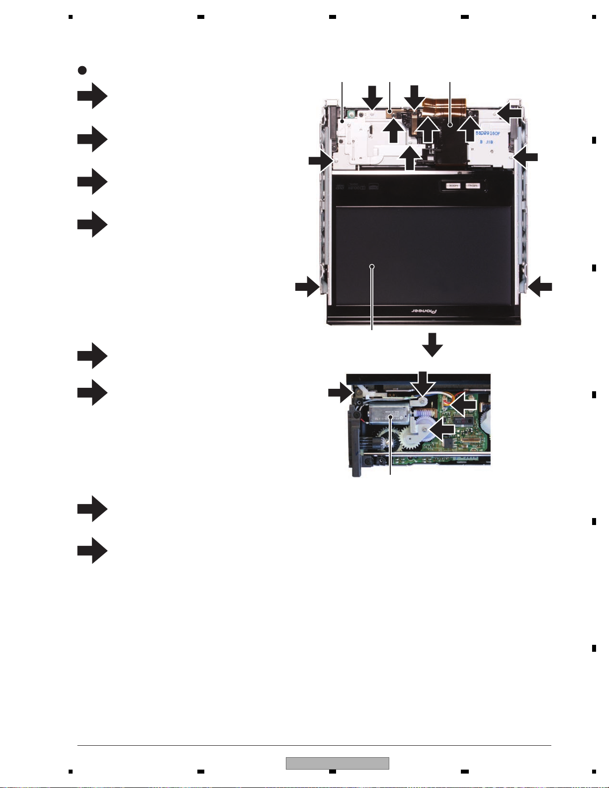
5678
56
7
8
C
D
F
A
B
E
1
2
Fig.6
Remove the two screws and then remove
the two Guids(Right side, Left side).
Pull out the Monitor Assy in the direction
indicated by an arrow.
Remove the two screws and then remove
the Spring.
Remove the screw and then remove
the Arm and Cover.
Disconnect the connector.
Remove the five screws and then remove
the Cover.
Disconnect the connector.
Remove the three screws and then remove
the Motor Unit.
Removing the Motor Unit, the Drive Unit
can operate to lead to the Monitor Assy.
1
2
3
Removing the Monitor PCB 1/2 (Fig.6)
Monitor Assy
Motor Unit
Arm and Cover
3
Cover
1
4
4
4
4
4
Spring
4
5
6
7
8
5
6
6
6
7 7
8
AVH-P6300BT/XNUC
91
Page 92
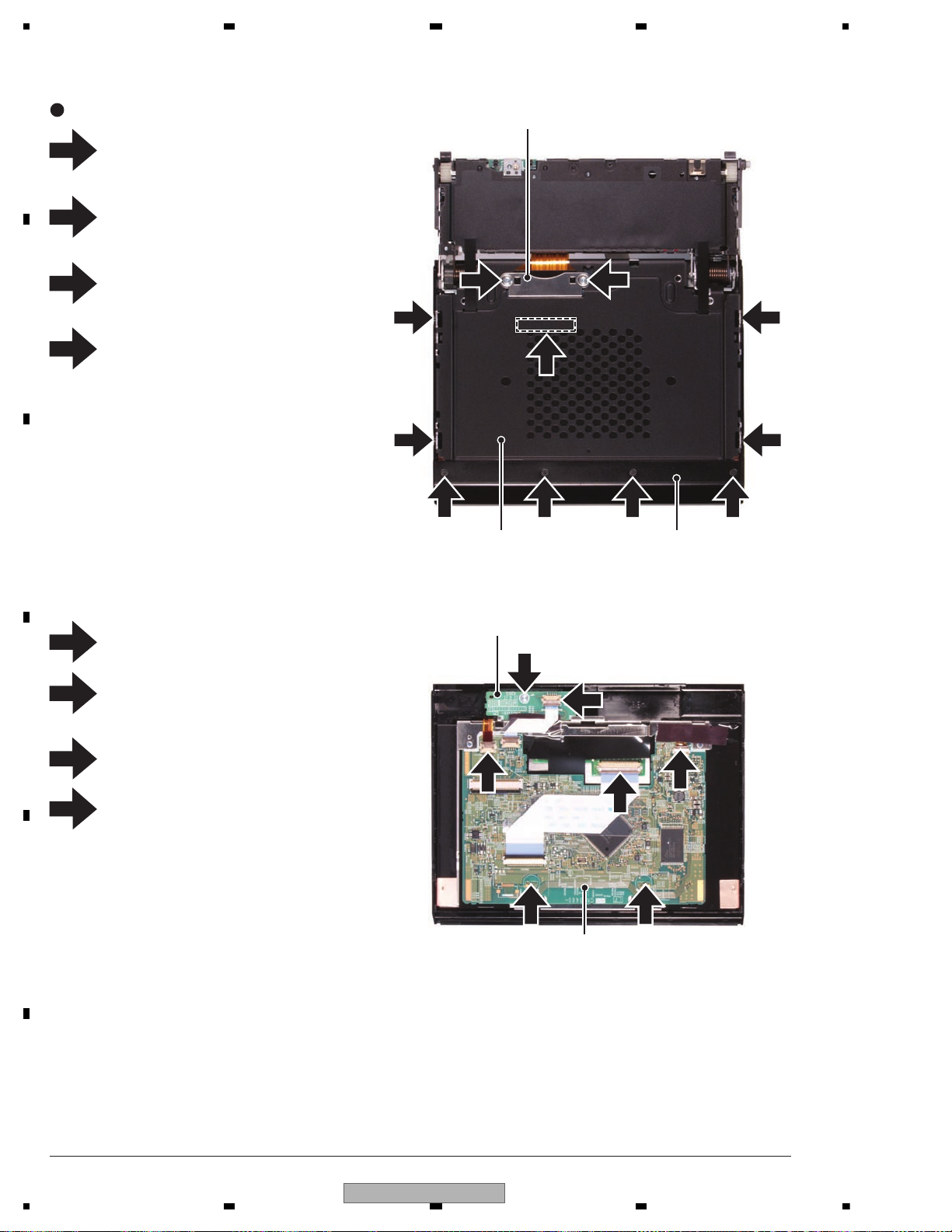
1234
1234
C
D
F
A
B
E
1
1
8
2
2
5
6 6
5
5
4
2 2
3 3
3 3
7
Remove the two screws and then remove
the Holder.
Remove the four screws and then remove
the Cover.
Remove the four screws and then remove
the Case Unit.
Disconnect the connector.
Disconnect the three connectors.
Straighten the tabs at two locations indicated and then remove the Monitor PCB.
Remove the screw.
Disconnect the connector and then remove
the Keyboard PCB.
1
2
3
4
5
6
7
8
Removing the Monitor PCB 2/2 (Fig.7)
Holder
Case Unit Cover
Keyboard PCB
Monitor PCB
Fig.7
92
AVH-P6300BT/XNUC
Page 93
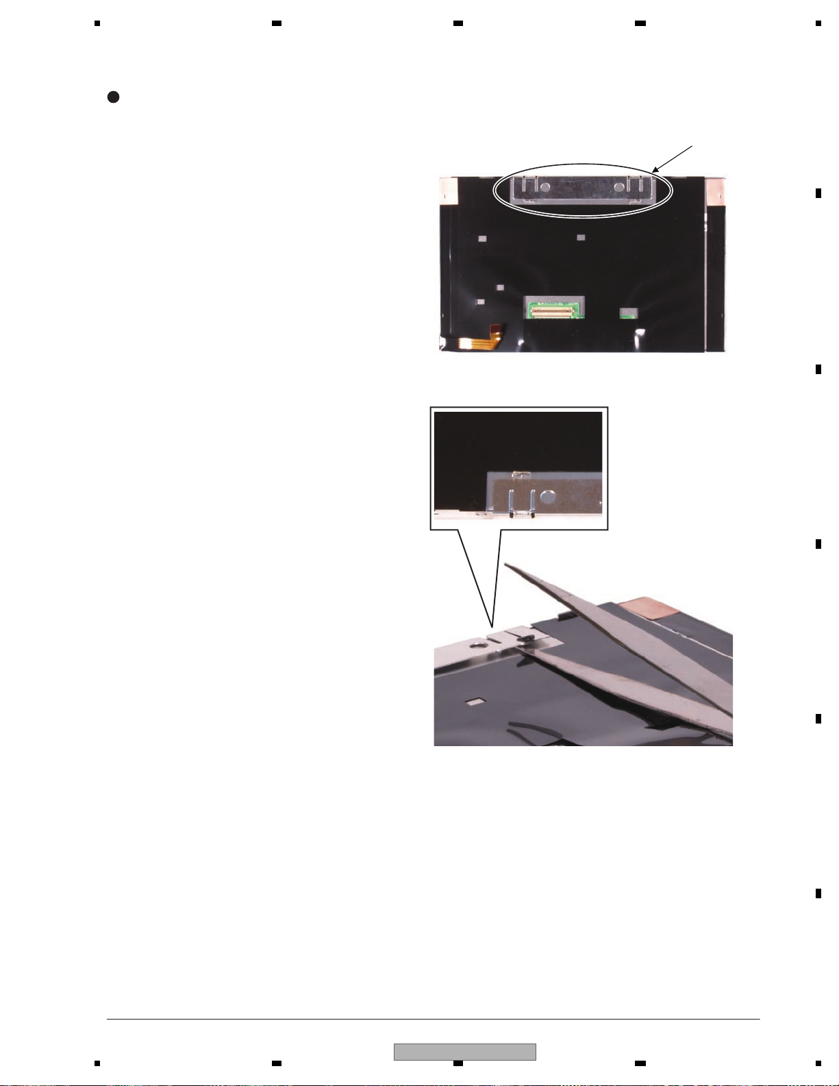
5678
56
7
8
C
D
F
A
B
E
Insert the tweezers (thin one) as shown in
the figure and remove the tab.
Caution
If you pick up the tab forcibly, the plate bends.
It can be removed by just inserting the
tweezers straightly.
Fig.8
Holder
Removing the Holder of LCD (Fig.8)
AVH-P6300BT/XNUC
93
Page 94
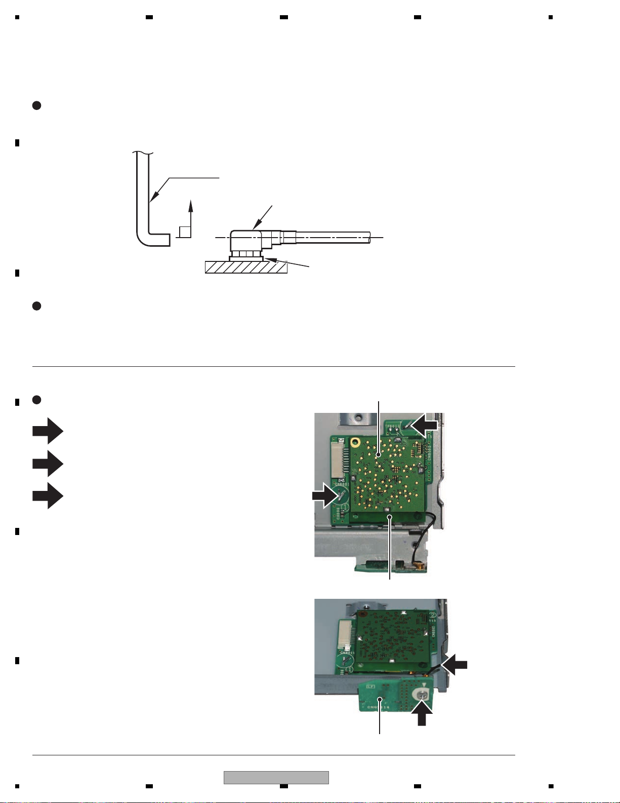
1234
1234
C
D
F
A
B
E
Fig.9
- - Removing the BT PCB and the BT ANT PCB (Fig.9)
Only BT model
Straighten the tabs at two locations indicated
and then remove the BT PCB.
Disconnect the Cord Assy using GGF1539.
Remove the screw and then remove the
BT ANT PCB.
1
1
2
3
1
2
3
BT ANT PCB
BT PCB
Connector
Coaxial Jumper
GGF1539
When unplugging the Coaxial Jumper, make sure to use jig GGF1539.
If the antenna cable is directly unplugged without using jig GGF1539, you might damage your fingertip or fingernail.
- -
How to Remove the Coaxial Jumper
- - When unplugging Coaxial Jumper, hook the point of jig GGF1539 on the lid of Coaxial Jumper
- - and vertically draw out along with the engagement axis of connector.
- -
How to Attach the Coaxial Jumper
- - For inserting Coaxial Jumper, adjust cord assy with the engagement axis of connector and insert it as vertically
- - as possible.
- - Do not insert the Coaxial Jumper in extreme slant, as the connector might suffer damage.
BT Module
94
AVH-P6300BT/XNUC
Page 95
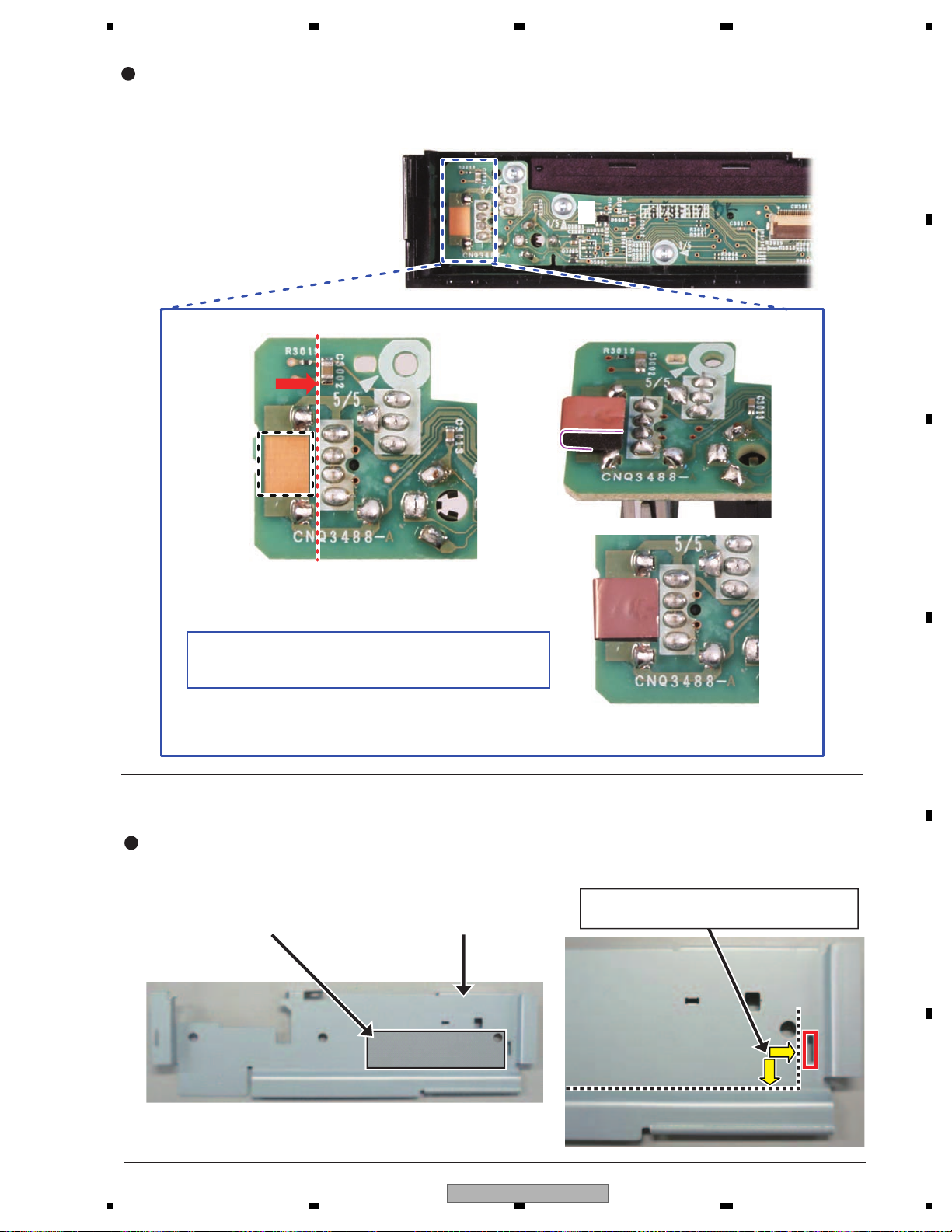
5678
56
7
8
C
D
F
A
B
E
Attention: How to install the Cushion
Align the cushion to PCB silk-print, and stick it.
Be careful not to touch the cushion to the USB terminal.
The sticking direction is shown on the right figure.
When you install the grille to the PCB, confirm the cushion is sticking on the Panel PCB properly.
Pasting position is shown below.
Align plate to bending line and square hole.
EMI Absorb Sheet (CNN3809) Holder (CND5511)
Attention: How to install the Sheet (AVH-P6300BT/XNUC)
AVH-P6300BT/XNUC
95
Page 96
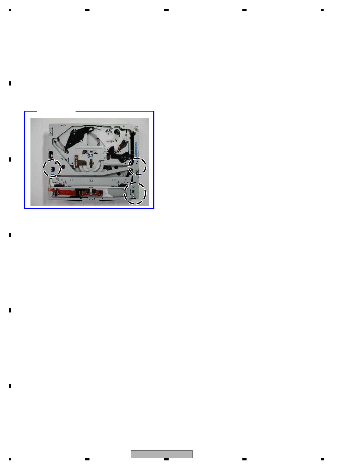
1234
1234
C
D
F
A
B
E
Handling OK
-How to hold the mechanism
1. Hold the specified parts (indicated by broken lines) of upper and lower frames.
2. Hold the main frame and the upper frame.
3. Do not hold the front part of the upper frame because the intensity is low.
4. Do not touch the switch on the ceiling surface of the mechanism. (Fig. 1)
5. Take care not to catch the flexible part on the side face.
6. Take note that a deformation may be generated if you hold the front part of the upper frame or CRG mechanism
part or a foreign object is inserted.
96
AVH-P6300BT/XNUC
Page 97
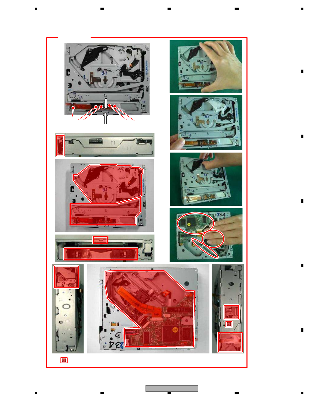
5678
56
7
8
C
D
F
A
B
E
Handling NG
Do not touch here
Do not touch here
Do not touch here
Fig. 1
: Do not touch here
AVH-P6300BT/XNUC
97
Page 98
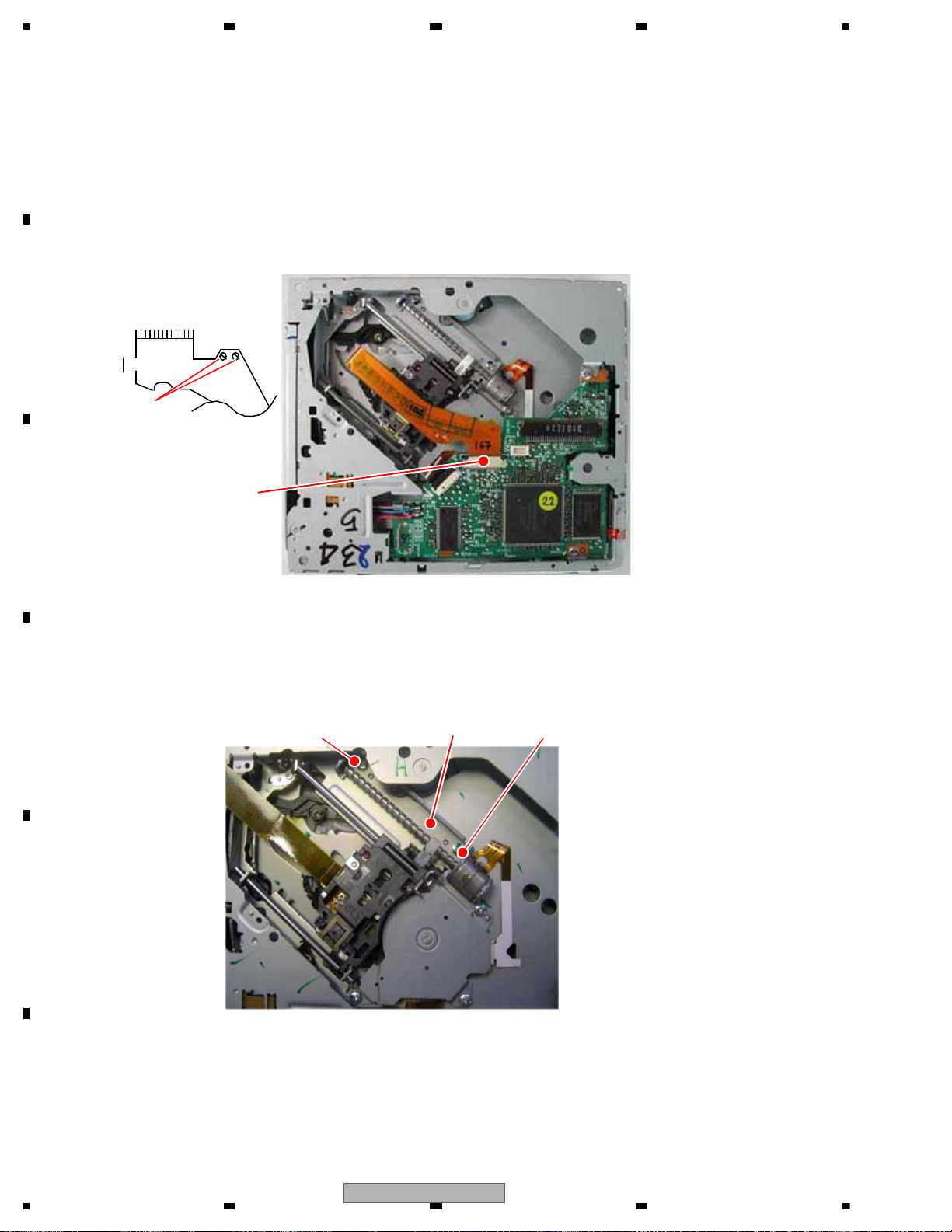
1234
1234
C
D
F
A
B
E
Fig. 2
Fig. 1
Connector
(pickup flexible part)
Short circuit
-How to remove the PU unit
1. Set the mechanism to the locking position (disc load standby position).
2. Set the ceiling surface of the mechanism module downward.
3. Short-circuit two parts of lands of the pickup flexible part. (Fig. 1)
4. Remove the connector of the pickup flexible part. (Fig. 2)
(The flexible part is damaged if the board is removed without removing the flexible part, so be sure to remove it.)
1. Unscrew two screws and remove the CRG motor ASS'Y.
Fig. 3
Locking screw (CRG) Locking screw (CRG)
CRG motor ASS’Y
98
AVH-P6300BT/XNUC
Page 99
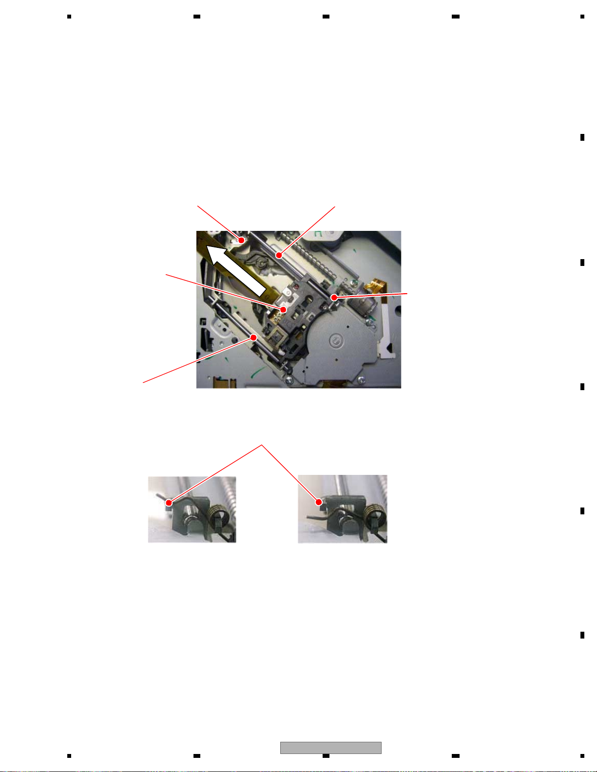
5678
56
7
8
C
D
F
A
B
E
1. Apply the main shaft holddown spring to the temporary applying part of CRG chassis.
2. Remove the CRG motor ASS'Y following “How to remove the CRG motor ASS'Y”.
3. Remove the retainer plate spring of the main shaft.
4. While holding up the tip of the pickup rack, slide the main shaft and remove the PU unit.
(Caution) When you attach the PU again, carry out the adjustment surely following the description in the
service manual of the mounted product.
Be sure to carry out the actual applying of main shaft holddown spring.
Retainer plate spring
Main shaft
PU unit
Main shaft holddown spring
Sub shaft
Fig. 4
Temporary applying part of CRG chassis
Actual applyingTemporary applying
AVH-P6300BT/XNUC
99
Page 100
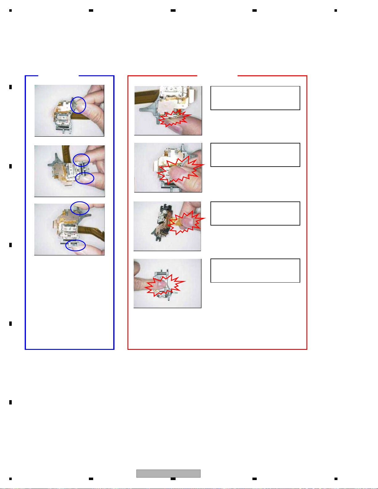
1234
1234
C
D
F
A
B
E
Do not touch the radiator.
Do not touch the ACT(object lens).
Do not pull the FPC.
Do not touch the Miller or
Collimator lens.
-How to hold PU (Fig. 5)
1. When you hold PU, hold “Handling OK” part shown in the figure and do not hold “Handling NG” part.
Fig. 5
Handling OK Handling NG
100
AVH-P6300BT/XNUC
 Loading...