

Page 1
21708-01
PSS SB PASSIVE JUNCTION
4
D Betriebsanleitung
4
GB Operating instructions
4
F Manuel d'utilisation
Sicherheitsbestimmungen
• Installieren und nehmen Sie die PSS SB
PASSIV JUNCTION nur dann in Betrieb,
wenn Sie diese Betriebsanleitung gelesen
und verstanden haben und Sie mit den
geltenden Vorschriften über Arbeitssicherheit
und Unfallverhütung vertraut sind.
Für den Einsatz der PSS SB ACTIVE
JUNCTION sind die Angaben und Anforderungen der "SafetyBUS p Installationsrichtlinien" gültig (siehe Systemhandbuch
SafetyBUS p). Beachten Sie die Ausführungen unbedingt, da sonst alle
Gewährleistungs-, Garantie- und Haftungsansprüche verloren gehen.
Beachten Sie darüber hinaus die Richtlinie
"SafetyBUS p - IP67 Physical Layer
Concept" des SafetyBUS p Club International
e. V.
Sicherheit
Bei der PSS SB PASSIVE JUNCTION
handelt es sich um kein sicherheits-
relevantes Gerät.
EMVG
Das Gerät ist für den Einsatz in Industrieumgebung bestimmt. Beim Einsatz im
Wohnbereich können Funkstörungen
entstehen.
ESD
ACHTUNG!
Durch elektrostatische Entladung
können Bauteile des Geräts
beschädigt werden. Sorgen Sie für
Entladung, bevor Sie das Gerät
berühren, z. B. durch Berühren
einer geerdeten, leitfähigen Fläche
oder durch Tragen eines geerdeten
Armbands.
Safety regulations
• Only install and commission the PSS SB
PASSIVE JUNCTION if you have read and
understood these operating instructions and
are familiar with the applicable regulations for
health and safety at work and accident
prevention.
The information and requirements stipulated
in the "SafetyBUS p Installation Manual" are
valid when using the PSS SB ACTIVE
JUNCTION (see SafetyBUS p System
Manual). Failure to comply with these
stipulations will render all warranty and
liability claims invalid.
The guidelines in the "SafetyBUS p - IP67
Physical Layer Concept" of the SafetyBUS p
Club International e. V. must also be met.
Safety
The PSS SB PASSIVE JUNCTION is not a
safety-related device.
EMCD
The device is designed for use in an
industrial environment. It is not suitable for
use in a domestic environment, as this can
lead to interference.
ESD
CAUTION!
Electrostatic discharge can damage
components on the device. Ensure
against discharge before touching
the device, e.g. by touching an
earthed, conductive surface or by
wearing an earthed armband.
Consignes de sécurité
• Vous n’installerez le PSS SB PASSIV
JUNCTION et ne le mettrez en service
qu’après avoir lu et compris le présent
manuel d’utilisation et vous être familiarisé
avec les prescriptions en vigueur sur la
sécurité du travail et la prévention des
accidents.
Pour l’utilisation du PSS SB ACTIVE
JUNCTION, les informations mentionnées
dans les « Directives d’installation du
SafetyBUS p » s’appliquent (voir le manuel
du système SafetyBUS p). Veuillez tenir
compte impérativement des explications car,
dans le cas contraire, tous les droits de
garantie ainsi que les revendications relatifs
à la responsabilité deviendront caducs.
Par ailleurs, veuillez respecter également la
directive « SafetyBUS p - IP67 Physical
Layer Concept » du SafetyBUS p Club
International e. V.
Sécurité
Le PSS SB PASSIVE JUNCTION n’est pas
un appareil de sécurité.
CEM
L’appareil est conçu pour fonctionner dans
un environnement industriel. Son utilisation
dans une habitation privée peut entraîner des
perturbations radioélectriques.
Décharge électrostatique
ATTENTION !
Les décharges électrostatiques
peuvent endommager des
éléments de l’appareil. Veuillez
vous décharger avant de toucher
l’appareil, par exemple, en
touchant une surface conductrice
mise à la terre ou en portant un
bracelet de mise à la terre.
Gewährleistung und Haftung
Gewährleistungs- und Haftungsansprüche
gehen verloren, wenn
• das Gerät nicht bestimmungsgemäß
verwendet wurde.
• die Schäden auf Nichtbeachtung der
Dokumentation zurückzuführen sind.
• das Betreiberpersonal nicht ordnungsgemäß ausgebildet ist.
• das Gehäuse geöffnet wurde.
• Veränderungen irgendeiner Art vorgenommen wurden (z. B. Austauschen von
Bausteinen auf den Leiterplatten,
Lötarbeiten usw.).
Warranty and liability
All claims to warranty and liability will be
rendered invalid if:
• The system was used contrary to the
purpose for which it is intended.
• Damage can be attributed to not having
followed the guidelines in the
documentation.
• Operating personnel are not suitably
trained or sufficiently qualified.
• The housing was opened.
• Any type of modification has been made
(e.g. exchanging components on the PCB
boards, soldering work etc.).
- 1 -
Garantie et responsabilité
Les droits de garantie et les revendications
ayant trait à la responsabilité sont perdus si
• l’appareil n’est pas utilisé conformément
aux prescriptions.
• les dommages ont été causés par le nonrespect de la documentation.
• le personnel exploitant n’a pas été formé
convenablement.
• le boîtier a été ouvert.
• des modifications de quelque type que ce
soit ont été apportées (par exemple
remplacement de composants des circuits
imprimés, travaux de soudage, etc.).
Page 2
Entsorgung
Entsorgen Sie das Gerät nach Ablauf seiner
Lebensdauer sachgerecht.
Disposal
The unit must be disposed of properly when
it reaches the end of its service life.
Fin de vie
Recycler l’appareil au bout de sa durée de
vie, conformément aux règles en vigueur.
INFO
Die Betriebsanleitung dient der
Instruktion. Bewahren Sie sie für
künftige Verwendung auf.
Bestimmungsgemäße Verwendung
Die PSS SB PASSIVE JUNCTION ist
bestimmt für den Einsatz in SafetyBUS pNetzwerken. Sie dient als Umsetzer von
IP20-Umgebung auf IP67-Umgebung.
Befinden sich die Feldgeräte in IP67Umgebung, muss geeignetes Kabel und
Verbindungsmaterial verwendet werden. Die
Angaben der Richtlinie "SafetyBUS p - IP67
Physical Layer Concept" des SafetyBUS p
Club International e.V. sind bindend.
Die Daten der PSS SB PASSIVE JUNCTION
sind im Abschnitt "Technische Daten“
festgelegt. Ein hiervon abweichender Einsatz
gilt als nicht bestimmungsgemäß. Jegliche
bauliche, technische oder elektrische
Veränderung gilt als nicht bestimmungsgemäß.
Wichtig: Beachten Sie die Sicherheitsbestimmungen, sonst erlischt
jegliche Gewährleistung.
Lieferumfang
• PSS SB PASSIV JUNCTION
• 4-poliger Schraubsteckverbinder
5-poliger Schraubsteckverbinder
• Betriebsanleitung
INFORMATION
This manual is intended for instruction
and should be retained for future
reference.
Intended use
The PSS SB PASSIVE JUNCTION is
designed for use in SafetyBUS p networks. It
is used to convert from an IP20 to an IP67
environment.
If the field devices are in an IP67
environment, suitable cable and connection
materials must be used. The information in
the guideline: "SafetyBUS p - IP67 Physical
Layer Concept", published by the SafetyBUS
p Club International e.V., is binding.
Details of the PSS SB PASSIVE JUNCTION
are provided in the "Technical details"
section. Use of the device outside the
specifications given here will be deemed as
improper use. Any component, technical or
electrical modifications will be deemed as
improper use.
Important: Failure to keep to these
safety regulations will render the
warranty invalid.
Range
• PSS SB PASSIVE JUNCTION
• 4-pin screw connector
5-pin screw connector
• Operating manual
INFORMATION
Le manuel d’utilisation sert à la
formation des utilisateurs. Veuillez
conserver ce manuel pour une
utilisation ultérieure.
Utilisation conforme aux prescriptions
Le PSS SB PASSIVE JUNCTION est destiné
à une utilisation dans les réseaux SafetyBUS
p. Il sert à convertir un environnement IP20
en environnement IP67.
Si les appareils de terrain se trouvent dans
un environnement IP67, il faut utiliser un
câble et un matériel de liaison appropriés.
Les informations mentionnées dans la
directive « SafetyBUS p - IP67 Physical
Layer Concept » du SafetyBUS p Club
International e.V. doivent être obligatoirement suivies.
Vous trouverez de plus amples informations
sur le PSS SB PASSIVE JUNCTION dans le
paragraphe « Caractéristiques techniques ».
Toute autre utilisation est considérée comme
non conforme. Toute modification
structurelle, technique ou électrique est
considérée comme non conforme.
Important : Respectez les consignes
de sécurité sinon la garantie devient
caduque.
Contenu de la livraison
• PSS SB PASSIV JUNCTION
• connecteur à vis débrochable à 4 broches
connecteur à vis débrochable à 5 broches
• manuel d’utilisation
Funktionsbeschreibung
Die PSS SB PASSIVE JUNCTION ist für den
Einsatz in SafetyBUS p-Netzwerken
konzipiert. Sie dient als Übergangspunkt
zwischen einem IP20-Strang und einem
IP67-Strang. Befinden sich Feldgeräte in
IP67-Umgebung, kann die Versorgungsspannung für die Feldgeräte über die PSS
SB PASSIVE JUNCTION eingespeist
werden. Verwenden Sie in diesem Fall ein
Buskabel das für die IP67-Umgebung
konzipiert ist. Das Kabel enthält außer den
Datenleitungen auch die Leitungen für die
Versorgungsspannung der Feldgeräte.
INFO
Zu Leitungslängen und Anzahl der
Feldgeräte beachten Sie die
"SafetyBUS p Installationsrichtlinien".
Function description
The PSS SB PASSIVE JUNCTION is
designed for use in SafetyBUS p networks. It
is used as a junction between an IP20
branch and an IP67 branch. If field devices
are in an IP67 environment, the supply
voltage for the field devices can be provided
via the PSS SB PASSIVE JUNCTION. In this
case you should use a bus cable designed
for the IP67 environment. In addition to the
data lines the cable also contains the voltage
supply lines for the field devices.
INFORMATION
Please refer to the "SafetyBUS p
Installation Manual" for details of cable
runs and the number of field devices.
Description du fonctionnement
Le PSS SB PASSIVE JUNCTION est conçu
pour une utilisation dans les réseaux
SafetyBUS p. Il sert de point de transition
entre un tronçon IP20 et un tronçon IP67. Si
les appareils de terrain se trouvent dans un
environnement IP67, la tension d’alimentation destinée aux appareils de terrain peut
être fournie par l’intermédiaire du PSS SB
PASSIVE JUNCTION. Dans ce cas, veillez à
utiliser un câble de bus approprié pour
l’environnement IP67. Ce câble renferme
non seulement les câbles de données mais
également les lignes nécessaires à la tension
d’alimentation des appareils de terrain.
INFORMATION
Pour les longueurs de câble et le
nombre d’appareils de terrain, tenez
compte des « Directives d’installation
du SafetyBUS p ».
- 2 -
Page 3
IP67IP20
24 V
0 V
Legende/Key/Légende :
MD
LD
I/OD
X2
X3
X1
X4
S
E
Versorgungsspannung/Supply voltage/Tension d’alimentation
Leitung/Line/Câble: Daten und Versorgungsspannung/Data and supply voltage line/Données et tension d’alimentation
Datenleitung/Data line/Câbles de données
Erdungsschiene/Earth bar/Rail de mise à la terre
Kabelschirm/Cable shield/Câble de blindage
Funktionserde/Functional earth/Mise à la terre
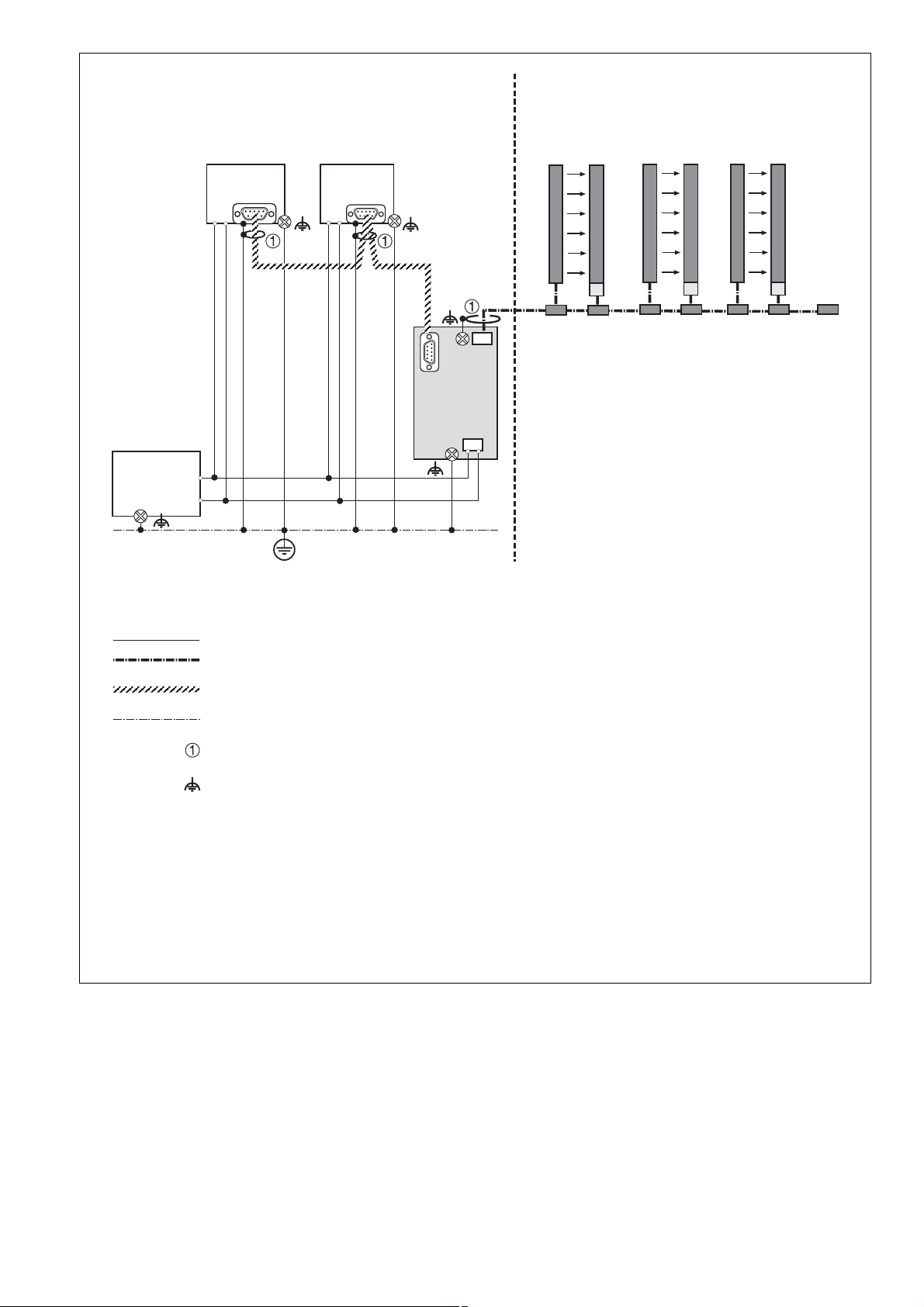
Fig. 1: IP20: Schaltschrank, IP67: Feld/IP20: Control cabinet, IP67: Field/IP20 : armoire électrique, IP67 : champ
- 3 -
Page 4

Gerätebeschreibung
Gerätemerkmale:
• Anschlussmöglichkeit für
- IP20-Strang (9-poliger Sub-D-Buchsenstecker)
- IP67-Strang (Schraubsteckverbinder X4)
- Versorgungsspannung (Schraubsteckverbinder X1)
• Anzeigeelement LED POWER:
Versorgungsspannung vorhanden
Unit description
Unit features:
• Connection option for:
- IP20 branch (female 9-pin D-Sub
connector)
- IP67 branch (screw connector X4)
- Supply voltage (screw connector X1)
• Display element LED POWER: Supply
voltage present
Description de l’appareil
Propriétés de l’appareil :
• Raccordements possibles pour
- tronçon IP20 (connecteur femelle Sub-D
à 9 broches)
- tronçon IP67 (connecteur à vis
débrochable X4)
- tension d’alimentation (connecteur à vis
débrochable X1)
• dispositif d’affichage LED POWER :
tension d’alimentation présente
Anschlussbelegung
Terminal assignment
2
IP20
Line
X2
X3
1
Passive Junction
X0
6
Shield
br-LOW
Shield
2345
1
IP67 Line X4
311059
Power
Power X1
3
2
1
24V
wt-GND
gn-HIGH
4
0V
Repérage des broches
rd-VCC
3
4
5
Legende/Key/Légende
1: SafetyBUS p -Schnittstelle/SafetyBUS p interface/Interface SafetyBUS p
2: Einpressbarer M4-Anschluss/M4 press fit connection/Raccordement M4 à presser
3: 5-polige Stiftleiste/5-pin male connector/Broche mâle à 5 pôles
4: LED POWER/LED POWER/LED POWER
5: 4-polige Stiftleiste/4-pin male connector/Broche mâle à 4 pôles
6: Einpressbarer M4-Anschluss/M4 press fit connection/Raccordement M4 à presser
Fig. 2
- 4 -
Page 5

Gewährleistung und Haftung
Warranty and liability
Garantie et responsabilité
SafetyBUS p für IP20
Die Verbindung zu SafetyBUS p (IP20) wird
über einen 9-poligen Sub-D-Stiftstecker
hergestellt.
6
9
Fig. 3: X2: 9-poliger Sub-D-Stiftstecker/X2: Male 9-pin D-Sub connector/X2: 9-poliger Sub-D-Stiftstecker
SafetyBUS p für IP67
Die Verbindung zu SafetyBUS p (IP67)
wird über einen 5-poligen Schraubsteckverbinder (X4) hergestellt.
1
5
SafetyBUS p for IP20
Connection to SafetyBUS p (IP20) is via a
male 9-pin D-Sub connector.
1: n.c.
2: CAN_L (brown/brown/marron)
3: CAN_GND (white/white/blanc)
4: n.c.
5: CAN_SHLD
6: n.c.
7: CAN_H (grün/green/vert)
8: n.c.
9: n.c.
n.c. = nicht belegt/not connected/non affecté
SafetyBUS p for IP67
Connection to SafetyBUS p (IP67) is via
a 5-pin screw connector (X4).
SafetyBUS p pour IP20
La connexion au SafetyBUS p (IP20) est
établie via un connecteur mâle Sub-D à
9 broches.
SafetyBUS p pour IP67
La connexion au SafetyBUS p (IP67)
est établie via un connecteur à vis
débrochable à 5 broches (X4).
1: Schirm/shield/Schirm (alternativer Anschluss/alternative connection/xxx)
X4
1234
Fig. 4: X4: 5-poliger Schraubsteckverbinder/X4: 5-pin screw connector/X4 : connecteur à vis débrochable à 5 broches
5
Montage
INFO
Beachten Sie das Kapitel "Installation
und Montage" der "SafetyBUS p
Installationsrichtlinien".
Die PSS SB PASSIVE JUNCTION ist auf
eine Normschiene aufschnappbar.
• Bauen Sie das Gerät in einen Schaltschrank mit einer Schutzart von
min. IP54 ein.
• Zur Befestigung auf einer Normschiene
dient ein Rastelement auf der Rückseite
des Geräts.
• Sichern Sie das Gerät bei Montage auf
einer senkrechten Tragschiene durch ein
Halteelement wie z. B. Endhalter oder
Endwinkel.
2: CAN_L (braun/brown/marron)
3: GND (weiß/white/blanc) (CAN_GND und/and/et VCC_GND)
4: GND (0V)
5: GND (0V)
Installation
INFORMATION
Please refer also to the chapter
entitled "Installation and Assembly" in
the "SafetyBUS p Installation
Manual".
The PSS SB PASSIVE JUNCTION is
suitable for DIN rail mounting.
• The device should be installed in a control
cabinet with a protection type
of at least IP54.
• There is a notch on the back of the unit for
DIN rail attachment.
• If you are installing the unit on to a vertical
DIN rail, ensure that it is mounted securely
by using a retaining bracket or an end
angle.
Montage
INFORMATION
Veuillez tenir compte du chapitre
« Installation et montage » des «
Directives d’installation du
SafetyBUS p ».
Le PSS SB PASSIVE JUNCTION est
encliquetable sur un rail normalisé.
• Installer l’appareil dans une armoire
possédant un indice de protection
d’au moins IP54.
• Un élément de fixation sur la face arrière
de l’appareil permet une installation sur un
rail normalisé.
• Immobiliser l’appareil monté sur un profilé
support vertical à l’aide d’un élément de
maintien, par exemple : un support
terminal ou une équerre terminale.
- 5 -
Page 6

Spannungsversorgung
X1
Supply voltage
1: +24 V DC
2: +24 V DC
3: 0 V
4: 0 V
Alimentation en tension
1234
Fig. 5: X1: 4-poliger Schraubsteckverbinder/X1: 4-pin screw connector/X1 : connecteur à vis débrochable à 4 broches
ACHTUNG!
• Beachten Sie die Angaben zur Toleranz
der Versorgungsspannung in den technischen Daten unbedingt. Außerhalb des
angegeben Bereichs ist ein sicherer
Betrieb nicht gewährleistet.
• Überspannungen oder Störspannungen
können die Elektronik des Geräts ganz
oder teilweise zerstören.
WARNUNG!
Achten Sie bei der 24-VVersorgungsspannung auf eine
sichere elektrische Trennung.
Andernfalls besteht die Gefahr von
elektrischem Schlag. Die Netzgeräte müssen EN 60742
(DIN VDE 0551) bzw. EN 50178
entsprechen.
Um eine möglichst geringe Restwelligkeit der
Spannung zu erreichen, empfehlen wir den
Einsatz von Drehstrom-Brückengleichrichtern
oder geregelten Netzteilen.
Isolationsspannungsprüfung
Die Busteilnehmer von Pilz sind durch
Schutzelemente an der Spannungs-
versorgung mit Funktionserde verbunden.
Isolationsspannungsprüfungen sind nur mit
Spannungen bis ca. 42 V möglich.
CAUTION!
• Ensure that you comply with the
information for supply voltage tolerance as
specified in the technical details. Safe
operation cannot be guaranteed outside
this range.
• Overvoltage or interference voltage can
damage or even destroy the electronics on
the device.
WARNING!
Safe electrical isolation must be
ensured for the external 24 V
supply. Failure to do so could result
in electric shock. Power supplies
must conform to EN 60742,
(DIN VDE 0551) or EN 50178.
To achieve the lowest possible residual
ripple, we recommend that you install a
three-phase bridge rectifier or regulated
supply.
Insulation voltage test
Pilz bus subscribers are connected to
functional earth via protection elements on
the voltage supply.
Insulation voltage tests are only possible with
voltages up to ca. 42 V.
ATTENTION !
• Respectez les valeurs des caractéristiques
techniques relatives à la tolérance de la
tension d’alimentation. Une exploitation en
toute sécurité n’est plus garantie en
dehors de cette plage.
• Des surtensions et des tensions parasites
peuvent détruire entièrement ou partiellement l’électronique de l’appareil.
AVERTISSEMENT !
Veiller à une séparation électrique
sécurisée pour la tension d’alimentation de 24 V. Dans le cas
contraire, il y a risque de choc
électrique. Les blocs d’alimentation
doivent être conformes aux normes
EN 60742, (DIN VDE 0551) et
EN 50178.
Pour réduire le plus possible l’ondulation
résiduelle de la tension, nous recommandons
l’installation de redresseurs en pont pour
courants alternatifs ou des blocs
d’alimentation régulés.
Contrôle de la tension d’isolement
Les abonnés du bus Pilz sont reliés à la mise
à la terre par des éléments de protection
placés sur l’alimentation en tension.
Les contrôles de la tension d’isolement ne
peuvent être effectués qu’avec des tensions
maximales d’environ 42 V.
Anschluss
Anschluss der Spannungsversorgung
• Schließen Sie die 24 V des Netzteils an
Klemmkontakt 1/2 der Klemmleiste X1 an.
• Schließen Sie die 0 V des Netzteils an
Klemmkontakt 3/4 der Klemmleiste X1 an.
Erdung
WICHTIG
Achten Sie auf die durchgehende
Verbindung des Kabelschirms in jedem
Strang. Stellen Sie die Verbindung für
die eingehende und abgehende
Busleitung in jedem Busstecker
fachgerecht her.
Connection
Supply voltage connection
• Connect the 24 V on the power supply to
terminal contact 1/2 on terminal block X1.
• Connect the 0 V on the power supply to
terminal contact 3/4 on terminal block X1.
Earthing
NOTICE
Ensure that the cable screening is
connected throughout in each branch.
Ensure the connection for the IN/OUT
bus cable is made correctly in each
bus connector.
- 6 -
Raccordement
Raccordement de l’alimentation en tension
• Raccorder les 24 V de l’alimentation sur la
borne de serrage 1/2 du bornier X1.
• Raccorder les 0 V de l’alimentation sur la
borne de serrage 3/4 du bornier X1.
Mise à la terre
IMPORTANT
Vérifier la liaison continue du câble de
blindage dans chaque tronçon. Etablir
une liaison appropriée de la ligne de
bus entrante et de la ligne de bus
sortante pour chaque connecteur de
bus.
Page 7

INFO
Beachten Sie die Angaben im Kapitel
"Installation und Montage" der
"SafetyBUS p Installationsrichtlinien".
IP20-Strang
Verbinden Sie den Kabelschirm einmal für
den gesamten Hauptstrang impedanzarm mit
der Schirmschiene oder Erdungsschiene
(Fig 1).
IP67-Strang
• Führen Sie den Kabelschirm des IP67Strangs auf einen der Anschlüsse der
beiden Klemmleisten X4 (SHIELD) oder
X3 (SHIELD).
INFO
Empfehlung: Legen Sie den Kabelschirm des IP67-Strangs an der
Klemme X3 (SHIELD) (siehe Fig. 2)
an.
INFORMATION
Please refer to the information in the
chapter entitled "Installation and
Assembly" in the "SafetyBUS p
Installation Manual".
IP20 branch
Connect the shielded screening with low
impedance to the screen bar or earth bar;
this only needs to be done once for the
whole main branch (Fig 1).
IP67 branch
• Connect the cable shield of the IP67
branch to one of the connections on the
two terminal blocks X4 (SHIELD) or X3
(SHIELD).
INFORMATION
Recommendation: Connect the cable
shield of the IP67 branch to terminal
X3 (SHIELD) (see Fig. 2).
INFORMATION
Veuillez tenir compte des indications
mentionnées dans le chapitre
« Installation et montage » des
« Directives d’installation du
SafetyBUS p ».
Tronçon IP20
Relier avec une faible impédance et une
seule fois le câble de blindage, pour
l’ensemble du tronçon principal, au rail de
blindage ou au rail de mise à la terre (fig. 1).
Tronçon IP67
• Amener le câble de blindage du tronçon
IP67 sur l’un des raccordements des deux
borniers X4 (SHIELD) ou X3 (SHIELD).
INFORMATION
Recommandation : appliquer le câble
de blindage du tronçon IP67 sur la
borne X3 (SHIELD) (cf. fig. 2).
• Verbinden Sie die Anschlüsse der
Klemmleiste X0 ( ) impedanzarm mit der
Schirmschiene oder Erdungsschiene (Fig.
1).
• Beachten Sie die Angaben der Richtlinie
"SafetyBUS p - IP67 Physical Layer
Concept" des SafetyBUS p Club International e.V.
Gerät in Betrieb nehmen
INFO
Beachten Sie das Kapitel "Inbetriebnahme" der "SafetyBUS p
Installationsrichtlinien".
Betrieb
Das Gerät ist betriebsbereit, wenn die LED
"POWER" dauerhaft leuchtet.
Abmessungen in mm (")
48 (1.88")
• Connect the X0 terminal block connections
( ) with low impedance to the screen bar
or earth bar (Fig. 1).
• Follow the guidelines in the "SafetyBUS p IP67 Physical Layer Concept" published
by the SafetyBUS p Club International e.V.
Commissioning the unit
INFORMATION
Please refer also to the chapter
entitled "Commissioning" in the
"SafetyBUS p Installation Manual".
Operation
The unit is ready for operation when the
"POWER" LED is lit continuously.
Dimensions in mm (")
72 (2.83)
• Relier, avec une faible impédance, les
raccordements du bornier X0 ( ) au rail
de blindage ou au rail de mise à la terre
(fig. 1).
• Respecter les indications mentionnées
dans les directives « SafetyBUS p - IP67
Physical Layer Concept » du SafetyBUS p
Club International e.V.
Mettre l’appareil en service
INFORMATION
Veuillez tenir compte du chapitre
« Mise en service » des « Directives
d’installation du SafetyBUS p ».
Utilisation
L’appareil est prêt à fonctionner lorsque la
LED « POWER » reste allumée.
Dimensions en mm (")
IP20
Line
X2
Shield
br-LOW
Shield
2345
1
X3
IP67 Line X4
Passive Junction
311059
Power
Power X1
X0
2
1
24V
wt-GND
3
0V
gn-HIGH
rd-VCC
4
96 (3.77")
Fig. 6: Abmessungen mit SafetyBUS p-Stecker/Dimensions with SafetyBUS p connector/Abmessungen mit SafetyBUS p-Stecker
- 7 -
Page 8

Technische Daten
Versorgungsspannung U
Spannungstoleranz
Leistungsaufnahme bei U
ohne Last
Galvanische Trennung
SafetyBUS p
Übertragungsrate
Leitungslänge
Übertragungsart
Klimabeanspruchung
EMV
Umgebungstemperatur
Lagertemperatur
Feuchtebeanspruchung
Betauung
Schutzart
Einbauraum (z. B. Schaltschrank)
Gehäuse
Klemmenbereich
Einbaulage
Anschlussart
Sub-D-Buchsenstecker
Schraubsteckverbinder
Querschnitt des Außenleiters
1 Leiter
flexibel
2 Leiter gleichen Querschnitts
flexibel mit Aderendhülse ohne
Kunststoffhülse
Anzugsdrehmoment der
Anschlussklemmen (Schrauben)
Gehäusematerial
Gehäuse
Fuß
Abmessungen H x B x T
Gewicht
B
B
Technical details
Supply voltage U
Voltage tolerance
Power consumption at U
without load
Galvanic isolation
SafetyBUS p
Transmission rate
Cable runs
Transmission type
Climatic suitability
EMC
Ambient temperature
Storage temperature
Climatic suitability
Condensation
Protection type
Mounting (e.g. control cabinet)
Housing
Terminals
Mounting position
Connection type
Female D-Sub connector
Screw connector
Cable cross section
1 core
flexible
2 core, same cross section
flexible with crimp connectors,
without insulating sleeve
Torque setting for
connection terminals (screws)
Housing material
Housing
Base
Dimensions H x W x D
Weight
B
B
Caractéristiques techniques
Tension d’alimentation U
Page de la tension d'alimentation
Consommation pour U
sans charge
Isolation galvanique
SafetyBUS p
Vitesse de transmission
Longueur de câble
Mode de transmission
Sollicitations climatiques
CEM
Température d'utilisation
Température de stockage
Sollicitation due à l’humidité
Condensation
Indice de protection
Lieu d’implantation (ex. armoire)
Boîtier
Borniers
Position de montage
Mode de raccordement
Connecteur Sub-D femelle
Connecteur à vis débrochable
Capacité de raccordement
1 conducteur
souple
2 câbles de même diamètre
souple avec embout sans
chapeau plastique
Couples de serrage des
borniers de raccordement (vis)
Matériau du boîtier
boîtier
socle
Dimensions H x L x P
Poids
B
B
24 V DC
85 ... 110%
3 mA zuzüglich Lastströme
des IP67-Strangs
(max. 3 A)/
3 mA plus load currents
from the IP67 branch
(max. 3 A)/
3 mA, plus les courants de
charge du tronçon IP67
(max. 3 A)
nein/no/non
max. 500 kBit/s
max. 3500 m
differenzielle
Zweidrahtleitung/
Differential two-wire cable/
deux fils différentiels
DIN IEC 60068-2-78
EN 61000-6-2
EN 55011
0 ... +60 °C
-25 ... +70 °C
DIN IEC 60068-2-78
max. 93 % r. F./r.h./HR
unzulässig/not permitted/
non admise
IP54
IP20
IP20
beliebig/any/indifférente
1 x 9-pol./1 x 9-pol./1 x 9
pôles
1 x 5-pol./1 x 5-pol./1 x 5
pôles
1 x 4-pol./1 x 4-pol./1 x 4
pôles
0,08 ... 2,5 mm
0,08 ... 1,5 mm
2
2
1,2 Nm
PA 6 UL 94-HB
PA 66 UL 94-V2
96 x 48 x 61 mm
(3.77" x 1.88" X 2.40")
88 g
Es gelten die 2007-03 aktuellen Ausgaben
der Normen.
A
Pilz Ges.m.b.H., ✆ 01 7986263-0, Fax: 01 7986264, E-Mail: pilz@pilz.at
safety@pilz.com.au
E-Mail: pilz@pilzbr.com.br
B L
CH
Pilz Belgium, ✆ 09 3217570, Fax: 09 3217571, E-Mail: info@pilz.be
Pilz lndustrieelektronik GmbH, ✆ 062 88979-30, Fax: 062 88979-40, E-Mail: pilz@pilz.ch
✆ 74436332, Fax: 74436342, E-Mail: pilz@pilz.dk
Electronic,
pilz.fi@pilz.dk
Fax: 031 789555, E-Mail: info@pilz.it
Ltd.,
info@mx.pilz.com
352, E-Mail: t.catterson@pilz.co.nz
Office,
SE
✆ 03 88104000, Fax: 03 88108000, E-Mail: siege@pilz-france.fr
GB
Pilz Automation Technology, ✆ 01536 460766, Fax: 01536 460866, E-Mail: sales@pilz.co.uk
IRL
✆ 045 471-2281, Fax: 045 471-2283, E-Mail: pilz@pilz.co.jp
✆ 021 62494658, Fax: 021 62491300,
Pilz Skandinavien K/S, ✆ 0300 13990, Fax: 0300 30740, E-Mail: pilz.se@pilz.dk
NL
Pilz Nederland, ✆ 0347 320477, Fax: 0347 320485, E-Mail: info@pilz.nl
P
Pilz Industrieelektronik S.L., ✆ 229407594, Fax: 229407595, E-Mail: pilz@pilz.es
✆ 0224 2360180, Fax: 0224 2360184, E-Mail: pilz.tr@pilz.de
info@pilzusa.com
www
www.pilz.com
D
Pilz GmbH & Co. KG, Sichere Automation, Felix-Wankel-Straße 2, 73760 Ostfildern, Deutschland, ✆ +49 711 3409-0, Fax: +49 711 3409-133,
E-Mail: pilz.gmbh@pilz.de
The standards current on 2007-03 apply. Les versions actuelles 2007-03 des normes
s'appliquent.
AUS
Pilz Australia, ✆ 03 95446300, Fax: 03 95446311, E-Mail:
BR
Pilz do Brasil, ✆ 11 4337-1241, Fax: 11 4337-1242,
DK
E
Pilz lndustrieelektronik S.L., ✆ 938497433, Fax: 938497544, E-Mail: pilz@pilz.es
Pilz Ireland Industrial Automation, ✆ 021 4346535, Fax: 021 4804994, E-Mail: sales@pilz.ie
MEX
E-Mail: sales@pilz.com.cn
USA
FIN
Pilz Skandinavien K/S, ✆ 09 27093700, Fax: 09 27093709, E-Mail:
Pilz de Mexico, S. de R.L. de C.V., ✆ 55 5572 1300, Fax: 55 5572 4194, E-Mail:
NZ
ROK
Pilz Automation Safety L.P., ✆ 734 354-0272, Fax: 734 354-3355, E-Mail:
Pilz Korea, ✆ 031 8159541, Fax: 031 8159542, E-Mail: info@pilzkorea.co.kr
TR
Pilz Elektronik Güvenlik Ürünleri ve Hizmetleri Tic. Ltd. ¸Sti.,
I
Pilz ltalia Srl, ✆ 031 789511,
Pilz New Zealand, ✆ 09- 6345-350, Fax: 09-6345-
PRC
Pilz China Representative
- 8 -
Pilz Skandinavien K/S,
F
Pilz France
J
Pilz Japan Co.,
21 708-01, 2007-03 Printed in Germany
 Loading...