

Page 1

Programmable Safety Systems
PSS-Range
PSS Standard Function Blocks
MBS Emergency Stop Circuits
Version 2.2
Operating Manual
Item No. 19 227-08
The spirit of safety.
Page 2

All rights to this manual are reserved by the publishers. Copies may be made for
internal purposes.
While every effort has been made to ensure that the information in this manual is
accurate, no responsibility can be accepted for errors or omissions contained within it.
We reserve the right to amend specifications without notice. We are grateful for any
feedback on the contents of this manual.
The names of products, goods and technologies used in this manual are trademarks of
the respective companies.
Page 3

Contents
Introduction 1-1
MBS Modular Block System 1-2
Categories / requirement classes 1-3
Overview of manual 1-4
Definition of symbols 1-5
Terminology 1-6
Overview 2-1
Software package 2-1
Range 2-2
Safety 3-1
Safety guidelines 3-1
Use of qualified personnel 3-1
Warranty and liability 3-1
Application guidelines 3-2
Standards 3-3
Fault detection 3-4
Fault detection techniques 3-5
Feasibility test 3-5
Pulsed input signals 3-6
Self test on the outputs 3-6
Fault prevention 3-6
Intended Use 4-1
System software 4-1
Intended use of the standard function blocks 4-2
SB060: Emergency stop monitoring 4-2
SB061: Emergency stop monitoring 4-2
SB062: Emergency stop monitoring 4-3
1Modular Block System: Emergency Stop Circuits
Page 4
Contents
SB063: Emergency stop monitoring 4-3
SB065: Feedback loop monitoring 4-4
SB067: Feedback loop monitoring 4-5
SB070: Initialisation of administration data block (DB015) 4-6
SB071: Initialisation of administration data blocks
(DB015/DB016/DB017) 4-6
MBS Basics 5-1
Block design 5-1
Structure 5-1
Formal parameters and actual parameters 5-2
Administration data blocks DB015, DB016 and DB017 5-3
Structure of the administration data blocks 5-3
Blocks contained in the administration data blocks 5-5
Input parameter SSNR 5-7
Fault diagnostics 5-9
Error types 5-9
Fault diagnostics using the administration data blocks 5-10
Temporary flag range in MBS blocks 5-11
Output parameter FG/ENBL 5-11
Assignment of input and output parameters 5-12
Minimum scan time 5-12
Global parameters 5-13
Standard Function Blocks 6-1
Guidelines for selecting standard function blocks 6-1
Emergency stop monitoring 6-1
SB060 NA_KAT_2 6-1
SB061 NA_1 6-1
SB062 E-STOP 6-2
SB063 E-STOP 6-2
Feedback loop monitoring 6-3
SB067 RFK_K4 6-3
SB065 FBL 6-3
2
Modular Block System: Emergency Stop Circuits
Page 5

Initialisation of administration data blocks 6-4
SB070 INIT_MBS 6-4
SB071 INIT_MBS 6-4
SB060: Emergency stop monitoring
Category 2 6-6
Block header 6-6
Input parameters 6-6
Output parameters 6-7
Error messages 6-7
Global parameters used in administration data block DB015 6-8
Blocks required 6-8
SB061: Emergency stop monitoring
Category 4 6-10
Block header 6-10
Input parameters 6-10
Output parameters 6-11
Error messages 6-11
Global parameters used in administration data block DB015 6-13
Blocks required 6-13
SB062: Emergency stop monitoring
Category 4 6-14
Block header 6-14
Input parameters 6-14
Output parameters 6-15
Function test 6-15
Error messages 6-16
Global parameters used in administration data block DB015 6-17
Blocks required 6-17
SB063: Emergency stop monitoring
Category 4 6-18
Block header 6-18
Input parameters 6-18
Output parameters 6-19
Function test 6-19
Error messages 6-20
Global parameters used in the administration data blocks 6-21
Blocks required 6-21
SB065: Feedback loop monitoring 6-22
Block header 6-22
Input parameters 6-22
3Modular Block System: Emergency Stop Circuits
Page 6

Contents
Output parameters 6-23
Functions 6-24
Error messages 6-25
Global parameters used in the administration data blocks 6-27
Blocks required 6-27
SB067: Feedback loop monitoring 6-28
Block header 6-28
Input parameters 6-28
Output parameters 6-28
Error messages 6-29
Global parameters used in administration data block DB015 6-30
Blocks required 6-30
SB070: Initialisation of administration data block
DB015 6-32
Block header 6-32
Input parameters 6-32
Function 6-32
Error messages 6-34
Blocks required 6-34
SB071: Initialisation of administration data blocks 6-36
Block header 6-36
Input parameters 6-36
Function 6-36
Error messages 6-38
Blocks required 6-38
Link Blocks 7-1
Check list 7-1
Examples 8-1
Application and parameters of individual blocks 8-1
Emergency stop monitoring
with manual start (start-up and operation), category 2 8-2
Emergency stop monitoring
with automatic start (start-up and operation), category 2 8-4
4
Modular Block System: Emergency Stop Circuits
Page 7

Emergency stop monitoring
with manual start (start-up and operation), category 4 8-6
Emergency stop monitoring
with automatic start-up, manual start (operation)
and function test, category 4 8-8
Feedback loop monitoring
Shutdown with two contactors connected in series,
category 4 8-10
Feedback loop monitoring
Shutdown with two main contactors connected in series and
pulsed outputs, category 4 8-12
Feedback loop monitoring (selective shutdown),
category 4 8-14
Emergency stop monitoring with monitoring of feedback loop,
category 4 8-18
Appendix 9-1
Assignment table
Category and requirement class 9-1
Standard function blocks: current versions 9-2
Changes to the standard function blocks 9-3
SB060: Emergency stop monitoring 9-3
SB061: Emergency stop monitoring 9-3
SB062: Emergency stop monitoring 9-4
SB063: Emergency stop monitoring 9-5
SB065: Feedback loop monitoring (RFK) 9-5
SB067: Feedback loop monitoring (RFK) 9-5
SB070: Initialisation of administration data block (DB015) 9-5
SB071: Initialisation of administration data blocks
(DB015/DB016/DB017) 9-6
Changes to the operating manual 9-6
Changes from Version 1.3 to Version 2.0 9-6
Changes from Version 2.0 to Version 2.2 9-6
5Modular Block System: Emergency Stop Circuits
Page 8

Page 9

Introduction
This manual describes how to manage the standard function blocks in the
“MBS Emergency Stop Circuits” software package in accordance with their
intended use.
Standard function blocks in the “MBS Emergency Stop Circuits” package
are part of the Pilz MBS Modular Block System. They can be used in the
failsafe section of a PSS-range programmable safety system.
To fully understand this manual you will need to be conversant with the
information found in the general documentation for the PSS-range
(System Manual, Installation Manual for the modular/compact PSS, PSS
SW PG Programming Manual/PSS WIN-PRO Programming Manual).
In particular you should refer to the following documents from the System
Manual:
• Safety Manual
• FS System Description
• Error List
To fully understand the bus-specific requirements and correlations for
SafetyBUS p applications you will need some knowledge of the design and
management of SafetyBUS p.
Knowledge of the safety regulations for the particular area of application is
assumed.
This installation manual is intended for instruction and should be retained
for future reference.
1-1Modular Block System: Emergency Stop Circuits
Page 10

Introduction
MBS Modular Block System
Safety-related areas can be equipped with a multitude of safety devices
such as E-STOPs, safety gates, light barriers etc. Safety devices are
required in various quantities and combinations, depending on the object
requiring protection. The Pilz MBS Modular Block System was developed
to drive the various safety devices and to carry out process engineering
functions, helping users to save time and money.
The MBS consists of individual standard function blocks (SBs), which are
geared specifically towards the relevant safety device or process
engineering function. It allows standard function blocks to be used in any
combination. The standard function blocks can be combined in any
sequence (max. 600).
Standard function blocks are encoded by an authorised body so that they
cannot be modified. If an encoded standard function block is used within
an application program, program testing may be restricted to the new parts
of the program, considerably reducing the test time.
1-2
Modular Block System: Emergency Stop Circuits
Page 11

Categories / requirement classes
EN 954-1 divides safety devices into categories.
All standard function blocks are designed for the highest category
permitted for the safety device to be monitored. If safety devices with lower
categories are to be monitored, input parameters may be assigned
identical inputs (further information can be found in the description for the
relevant standard function block).
In process engineering, safety requirements must conform to DIN V 19250
(Basic Safety Requirements for Measurement and Control Protection
Devices).
Requirement classes in accordance with DIN V 19250 may be referred to
the categories as per EN 954-1. The Appendix contains a table showing
the assignment of category ↔ requirement class.
1-3Modular Block System: Emergency Stop Circuits
Page 12

Introduction
Overview of manual
1 Introduction
The chapter you are reading provides an introduction to the Modular
Block System (MBS). It is designed to familiarise you with the
contents, structure and specific order of this manual and also contains
terminology definitions.
2 Overview
This chapter provides information on the most important features of
the software package and provides a brief overview of the application
range.
3 Safety
This chapter must be read as it contains important information on
safety regulations.
4 Intended Use
This chapter must be read as it contains information on intended use.
5 MBS Basics
This chapter explains the basic functions and safety requirements of
the MBS.
6 Standard Function Blocks
This chapter explains the function of the standard function blocks in
the software package.
7 Link Blocks
This chapter is designed to help you link the standard function blocks
into your project and to commission the safety functions.
8 Examples
This chapter is designed to give an overview of how the standard
function blocks may be applied and contains typical application
examples.
9 Appendix
The Appendix contains a table that explains the relationship between
categories and requirement classes, plus a list that documents the
current version status of the standard function blocks.
1-4
Modular Block System: Emergency Stop Circuits
Page 13

Definition of symbols
Information in this manual that is of particular importance can be identified
as follows:
DANGER!
This warning must be heeded! It warns of a hazardous situation that
poses an immediate threat of serious injury and death and indicates
preventive measures that can be taken.
WARNING!
This warning must be heeded! It warns of a hazardous situation that
could lead to serious injury and death and indicates preventive
measures that can be taken.
CAUTION!
This refers to a hazard that can lead to a less serious or minor injury plus
material damage, and also provides information on preventive measures
that can be taken.
NOTICE
This describes a situation in which the product or devices in its immediate
environment could be damaged. It also provides information on preventive
measures that can be taken.
INFORMATION
This gives advice on applications and provides information on special
features, as well as highlighting areas within the text that are of particular
importance.
1-5Modular Block System: Emergency Stop Circuits
Page 14

Introduction
Terminology
• The term “input” is frequently abbreviated to “I” (e.g. I-Parameter).
• The term “output” is frequently abbreviated to “O” (e.g. O-Parameter).
• The term “PSS” is always used when the description is valid for all
applicable PSS programmable safety systems. If the description only
relates to a specific PSS series, the specific name for that series will be
used (e.g. PSS 3000 or PSS SB 3056).
• In this manual, the system software “PSS SW PG” and “PSS WIN-PRO”
is referred to as “programming device” or “PG”.
1-6
Modular Block System: Emergency Stop Circuits
Page 15

Overview
Software package
The “MBS Emergency Stop Circuits” software package is part of the Pilz
MBS Modular Block System. The software package contains all the
standard function blocks necessary for electronically-monitored safety
devices on distributed automation plants. This includes:
• Evaluation of E-STOP buttons, grab wires etc.
• Monitoring safety, maintenance and supply gates
Standard function blocks in the “MBS Emergency Stop Circuits” software
package are used in the failsafe section of a PSS-range programmable
safety system.
Range
The software package consists of:
• The files for the software package on CD and
• An operating manual:
PSS Standard Function Blocks MBS Emergency Stop Circuits, Version
2.0
The software package on the CD contains the following standard function
blocks:
• SB060 NA_Kat_2
Monitoring E-STOP button up to category 2 in accordance with
EN 954-1, 03/97 and AK 3 in accordance with DIN V 19 250,
01/89
(approved safety block)
• SB061 NA_1
Monitoring E-STOP button up to category 4 in accordance with
EN 954-1, 03/97 and AK 6 in accordance with DIN V 19 250,
05/94
(approved safety block)
• SB062 E-STOP
Monitoring E-STOP button up to category 4 in accordance with
EN 954-1, 03/97 and AK 6 in accordance with DIN V 19 250,
05/94
(approved safety block)
2-1Modular Block System: Emergency Stop Circuits
Page 16

Overview
• SB063 E-STOP
Monitoring E-STOP button up to category 4 in accordance with
EN 954-1, 03/97 and AK 6 in accordance with DIN V 19 250,
05/94
(approved safety block)
• SB065 FBL
Feedback loop monitoring
(approved safety block)
• SB067 RFK_K4
Feedback loop monitoring
(approved safety block)
• SB070 INIT_MBS
Initialisation of the administration data block (DB015)
(approved safety block)
• SB071 INIT_MBS
Initialisation of the administration data blocks (DB015/DB016/
DB017)
(approved safety block)
• SB255 System block
SB255 is described in the PSS System Description
2-2
Modular Block System: Emergency Stop Circuits
Page 17

Safety
Safety guidelines
These safety guidelines are an important part of this manual. Failure to
keep to these guidelines will render all warranty, guarantee and liability
claims invalid.
• All health and safety / accident prevention regulations for the particular
area of application must be observed.
• Before using one or more of the standard function blocks in this software
package, you must perform a safety assessment in accordance with the
Machinery Directive.
Use of qualified personnel
The package may only be assembled, installed, commissioned, operated,
maintained and decommissioned by qualified personnel who, because
they are
• Qualified electrical engineers and/or
• Have received training from qualified electrical engineers
are suitably experienced to operate devices, systems, plant and machinery
in accordance with the general standards and guidelines for safety
technology.
Warranty and liability
All claims to warranty and liability will be rendered invalid if:
• Standard function blocks are used contrary to the purpose for which they
were intended
• Damage can be attributed to not having followed the guidelines in the
manual
• Operating personnel are not suitably qualified.
3-1Modular Block System: Emergency Stop Circuits
Page 18

Safety
Application guidelines
• The instructions given in the “Safety Manual” and in the “Installation
Manual” must be followed.
• Please read the information in Chapter 4 regarding the intended use of
these blocks.
• The use of Pilz SBs does not detract from the fact that it is the
responsibility of the user to design appropriate safety systems for plant,
machinery and software.
• It is the users' responsibility to determine their application requirements
by carrying out a detailed risk analysis, which should take into account
relevant regulations and standards, etc.
WARNING!
Please note: To achieve the corresponding category or requirement class,
the whole system including all safety-related components (parts, devices,
user program etc.) must be included in the assessment. For this reason,
Pilz cannot accept liability for the correct classification into a category or
requirement class.
3-2
Modular Block System: Emergency Stop Circuits
Page 19

Standards
To use the SBs correctly you will need to have a good knowledge of the
relevant standards and directives. The following gives an overview of the
most important standards:
• E-STOP circuits EN 418
• Safety of machinery -
Two-hand controls EN 574
• Mechanical presses EN 692
• Hydraulic presses EN 693
• Hydraulic stamping and bending presses EN 12 622
• Machinery directive- basic terminology EN 292-1 and EN 292-2
• Printing and paper machinery prEN 1010
• Safety gates EN 1088
• Electrosensitive protective equipment EN 61 496-1
• Electrical equipment EN 60 204-1
• Machinery safety EN 954-1
• Basic Safety Requirements for Mea-
surement and Control Protection Devices DIN V 19 250
• Electrical equipment on firing plants prEN 50 156-1
Please note this is not an exhaustive list of safety standards and
directives.
3-3Modular Block System: Emergency Stop Circuits
Page 20

Safety
Fault detection
The detection of errors and defects is an important function of the PSS, in
addition to pure control tasks.
Potential faults are subdivided into:
• Errors in the system hardware and wiring errors in the periphery units:
• Feasibility errors and functional errors in the process periphery units
- Errors in the system hardware are automatically detected and managed
by the PSS
- If test signals are used, wiring errors in the periphery units will
automatically be detected and managed by the PSS.
Users do not need to take this type of error into account within the
application program (additional information can be found in the PSS
“System Description”).
(input devices, actuators, wiring etc.).
These errors must be detected and managed through the PSS control
program.
WARNING!
It is particularly important to detect open circuits and shorts within the
safety circuits (e.g. two-hand, E-STOP etc.)
It is the responsibility of the user to select and apply an appropriate fault
detection system.
3-4
Modular Block System: Emergency Stop Circuits
Page 21

Fault detection techniques
Various options are available to the user to help detect and rectify errors in
the process periphery units:
• Errors can be detected via the feasibility checks in the application program, e.g. by using redundant input devices.
• Errors can be detected by pulsing the signal lines using the test pulses
from the PSS DI2O T module.
• Errors can be detected by using the automatic tests in the output
modules.
• Avoid potential errors by using appropriate wiring.
Additional information on how to exclude potential errors can be found in
the directive VDI 2854 (safety requirements on automated manufacturing
systems).
Feasibility test
Redundant input devices for safety functions must undergo a feasibility
test within the application program.
Example:
A two-hand button has a N/C and a N/O contact. Once the application
program has detected the open N/C contact, it must check that the N/O
contact closes within an appropriate period of time. The function test
must be carried out for all possible combinations of the two contacts.
The plant must be stopped immediately if a feasibility error occurs. Similar
tests will also be required for other input devices.
If safety valves have feedback contacts, these must be evaluated
accordingly.
3-5Modular Block System: Emergency Stop Circuits
Page 22

Safety
Pulsed input signals
Input devices for inputs with infrequent operation (e.g. E-STOP, off
buttons, etc.) must be pulsed using test signals. The connection of test
pulses to input devices is described in the “Installation Manual”.
Test pulses should also be used for input devices which have an important
safety function and frequent operation (e.g. two-hand, camshaft etc.).
Self test on the outputs
PSS output modules regularly carry out function tests. Using these tests,
dual-pole switching output modules on the PSS are automatically able to
detect and deal with open circuits, short circuits and external power
sources in the periphery wiring.
Single-pole switching output modules can detect short circuits but not
open circuits.
Fault prevention
Not all potential faults can be detected and managed. Such faults must be
excluded by suitable wiring.
Example: If the feed to the input device and the feedback from the input
device to the input use the same multicore cable, a short circuit between
the two wires could short out the input device. Such a fault would go
undetected.
3-6
Modular Block System: Emergency Stop Circuits
Page 23
Intended Use
The software package “MBS Emergency Stop Circuits” is designed for use
within the failsafe section of the PSS-range of programmable safety
systems.
INFORMATION
Use of standard function blocks outside the specifications described here
will be deemed improper use.
INFORMATION
Always use the current version of a standard function block. Please
ensure you refer to the Appendix, sections entitled “Standard function
blocks: current versions” and “Changes to the standard function blocks”.
System software
The software package “MBS Emergency Stop Circuits” can be used with
the following system software:
• PSS SW PG
• PSS WIN-PRO
INFORMATION
Depending on the programming language selected on PSS WIN-PRO,
designations for formal parameters and operands may differ from those
found on PSS SW PG. Any designations that are different will
automatically be replaced by PSS WIN-PRO .
Further information is available in the programming manual for “PSS SWPG” or “PSS WIN-PRO”.
4-1Modular Block System: Emergency Stop Circuits
Page 24

Intended Use
Intended use of the standard function blocks
SB060: Emergency stop monitoring
SB060 is a standard function block for monitoring single-channel E-STOP
buttons up to category 2, in accordance with EN 954-1, 11/94 and AK 3, in
accordance with DIN V 19 250, 01/89. It is also possible to use SB 060 to
monitor safety gates and light barriers up to category 2, in accordance
with EN 954-1.
Operating modes:
• With or without start-up reset on cold-start
• With or without automatic reset when E-STOP is released
INFORMATION
Input circuitry:
• Use E-STOP button with test pulses
SB061: Emergency stop monitoring
SB061 is a standard function block for monitoring E-STOP buttons up to
category 4, in accordance with EN 954-1, 03/97 and AK 6, in accordance
with DIN V 19 250, 05/94. It is also possible to use SB061 to monitor
safety gates up to category 4, in accordance with EN 954-1, 03/97.
Operating modes:
• With or without start-up reset on cold-start
• With or without automatic reset when E-STOP is released
INFORMATION
Input circuitry:
• Use E-STOP button with test pulses
• When using SB061 for category 4 applications:
- use dual-channel elements
• When using SB061 for category 2 applications:
- use single-channel elements
4-2
Modular Block System: Emergency Stop Circuits
Page 25

SB062: Emergency stop monitoring
SB062 is a standard function block for monitoring E-STOP buttons up to
category 4, in accordance with EN 954-1, 03/97 and AK 6, in accordance
with DIN V 19 250, 05/94. It is also possible to use SB 062 to monitor
safety gates up to category 4, in accordance with EN 954-1, 03/97.
Operating modes:
• With or without start-up reset on cold-start or on a SafetyBUS group
start
• With or without automatic reset when E-STOP is released
• With or without prompt for function test after a synchronisation error
when the E-STOP is released
INFORMATION
Input circuitry:
• Use E-STOP button with test pulses
• When using SB062 for category 4 applications:
- use dual-channel elements
• When using SB062 for category 2 applications:
- use single-channel elements
SB063: Emergency stop monitoring
SB063 is a standard function block for monitoring E-STOP buttons up to
category 4, in accordance with EN 954-1, 03/97 and AK 6, in accordance
with DIN V 19 250, 05/94. It is also possible to use SB063 to monitor
safety gates up to category 4, in accordance with EN 954-1, 03/97.
INFORMATION
On SB063, the SSNR may lie in the range of 1 to 600.
Operating modes:
• With or without start-up reset on cold start or on a SafetyBUS p group
start
4-3Modular Block System: Emergency Stop Circuits
Page 26

Intended Use
• With or without automatic reset when E-STOP is released
• With or without prompt for function test after a synchronisation error
when the E-STOP is released
INFORMATION
Input circuitry:
• Use E-STOP button with test pulses
• When using SB063 for category 4 applications:
- use dual-channel elements
• When using SB063 for category 2 applications:
- use single-channel elements
SB065: Feedback loop monitoring
SB065 is a standard function block for the direct control and monitoring of 1
or 2 contactors up to category 4, in accordance with EN 954-1, 03/97.
INFORMATION
On SB065, the SSNR may lie in the range of 1 to 600.
Features and application areas:
• Feedback loop is monitored during the change in the switch signal and
while the contactors are in a static condition.
• Feedback loop can be monitored on two separate feedback loops of
contactors connected in series
• Feedback loop can be monitored on two separate feedback loops of
contactors connected in parallel
• Feedback loop can be monitored on group contactors
• Selectable time for feedback loop monitoring
• Parameter to suppress error messages when an I/O-Group stops
(SafetyBUS p)
INFORMATION
Input circuitry:
4-4
• To achieve category 4, two independent shutdown routes must be
provided within the current path of the potentially dangerous drive
Modular Block System: Emergency Stop Circuits
Page 27

• If wiring is to be laid outside the control cabinet, feedback loops must use
test pulses.
• Feedback loops must use test pulses if the possibility of a short-circuit
cannot be excluded.
• If only one contactor is used to switch a potentially dangerous drive, it
must be possible to switch this off via a group contactor within the
current path (selective shutdown).
• The group contactor must also be monitored through a feedback loop.
SB067: Feedback loop monitoring
SB067 is a standard function block for the direct control and monitoring of
contactors up to category 4, in accordance with EN 954-1, 03/97.
Features and application areas:
• Feedback loop is monitored during the change in the enable flag and
while the contactor is in a static condition.
• Feedback loop can be monitored on two separate feedback loops of
main contactors connected in series.
• Feedback loop can be monitored on group contactors.
INFORMATION
Input circuitry:
• To achieve category 4, two independent shutdown routes must be
provided within the current path of the potentially dangerous drive.
• If wiring is to be laid outside the control cabinet, feedback loops must use
test pulses.
• Feedback loops must use test pulses if the possibility of a short-circuit
cannot be excluded.
• If only one relay is used to switch a potentially dangerous drive, it must
be possible to switch this off via a group contactor located within the
current path (selective shutdown).
• The group contactor must also be monitored through a feedback loop.
4-5Modular Block System: Emergency Stop Circuits
Page 28

Intended Use
SB070: Initialisation of administration data block (DB015)
SB070 is used to calculate the global parameters, depending on the set
minimum scan time (see also under “Minimum Scan Time” in Chapter 5).
The global parameters in administration data block DB015/DW1001 ... DW
1023 are initialised using SB070.
Function:
• Reads in the set minimum scan time from DB002 (configurator)
• Calculates the cycles based on the times transferred in the parameters
• Enters the calculated values into the administration DB.
SB071: Initialisation of administration data blocks (DB015/DB016/DB017)
SB071 is used to calculate the global parameters, depending on the set
minimum scan time (see also under “Minimum Scan Time” in Chapter 5).
Global parameters DW1001 ... DW1023 in administration data blocks
DB015, DB016 and DB017 are initialised using SB071.
Function:
• Reads in the set minimum scan time from DB002 (configurator)
• Calculates the cycles based on the times transferred in the parameters
• Enters the calculated values into the administration data blocks.
NOTICE
It is absolutely essential that SB071 is called in OB120 when using the
following standard function blocks:
• SB063 E-STOP
• SB064 S-GATE
• SB065 FBL
4-6
Modular Block System: Emergency Stop Circuits
Page 29

MBS Basics
Block design
Structure
Safety-related areas can be equipped with a multitude of safety devices
such as (e.g. E-STOPs, safety gates, light barriers). These safety devices
are used in various quantities and combinations, depending on the object
requiring protection.
The Modular Block System (MBS) is made up of individual standard
function blocks. A standard function block is geared towards the
requirements of specific safety devices (e.g. monitoring an E-STOP
button, safety gate monitoring).
A standard function block must be assigned to each safety device in order
for it to be evaluated and monitored using the MBS. This procedure
enables any combination of individual safety devices to be evaluated and
monitored. The standard function blocks can be combined in any
sequence within the user program (max. 600).
One exception to this are standard function blocks used to drive and
monitor contactors or valves. For control engineering reasons, these
should be called up at the end of the user program.
5-1Modular Block System: Emergency Stop Circuits
Page 30
MBS Basics
Formal parameters and actual parameters
Parameters can be set on the MBS standard function blocks. Formal
parameters are established in the block header. The user must assign a
corresponding actual parameter to each formal parameter. When the
standard function block is called up in the user program, the formal
parameters will be replaced by the user-specific actual parameters.
Formal parameter
PSS SW PG
PSS WIN-PRO: Pilz IL
X
B
W
D
Z
INFORMATION
Depending on the programming language selected on PSS WIN-PRO,
designations for formal parameters and operands may differ from those
found on PSS SW PG. Any designations that are different will
automatically be replaced by PSS WIN-PRO.
Actual parameter
PSS SW PG
PSS WIN-PRO: Pilz IL
Input bit E
Output bit A
Flag bit M
Input byte EB
Output byte AB
Flag byte MB
Constant KB
Input word EW
Output word AW
Flag byte MW
Constant KW
Data block DB
Timer or counter
5-2
Further information is available in the programming manual for “PSS SWPG” or “PSS WIN-PRO”.
Modular Block System: Emergency Stop Circuits
Page 31

Administration data blocks DB015, DB016 and DB017
Data blocks DB015, DB016 and DB017 are permanently specified within
the Modular Block System (MBS).
These data blocks are common administration blocks for fault and
diagnostic data from the MBS standard function blocks and for block and
parameter data that is required internally.
The administration data block DB015 must always be installed when using
MBS standard function blocks. Administration data blocks DB016 and
DB017 are installed when necessary.
The administration data blocks must always be installed with their full
length of 1024 data words and they must always have read/write status.
NOTICE
Data blocks DB015, DB016 and DB017 should only be used as MBS
administration data blocks and not for other data.
Structure of the administration data blocks
The administration data blocks DB015, DB016 and DB017 have the same
structure.
Each standard function block in the user program has 5 data words
available in one of the administration data blocks. These data words are
used to back up the temporary flags from the standard function block (see
section entitled “Temporary flag range in MBS blocks”).
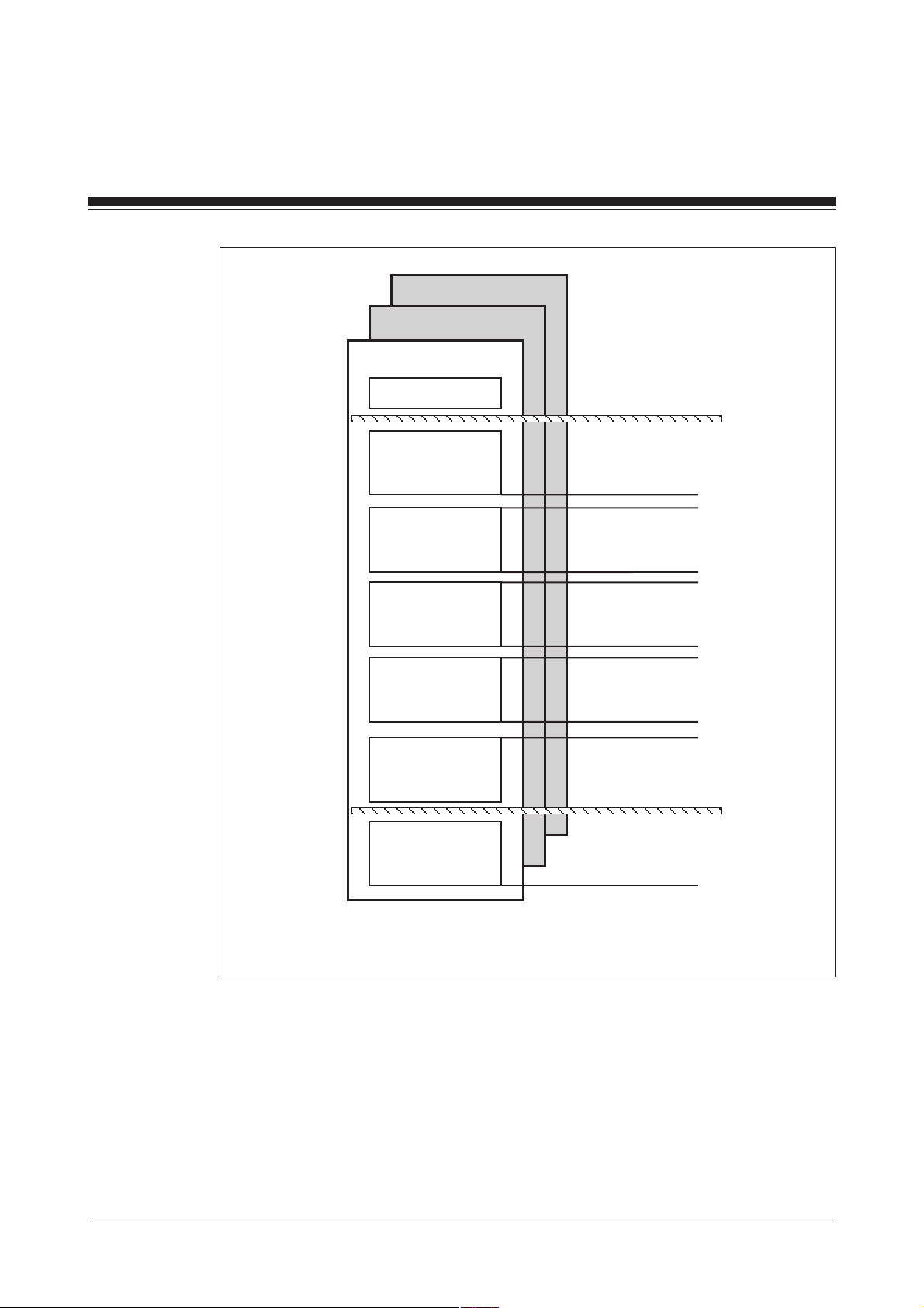
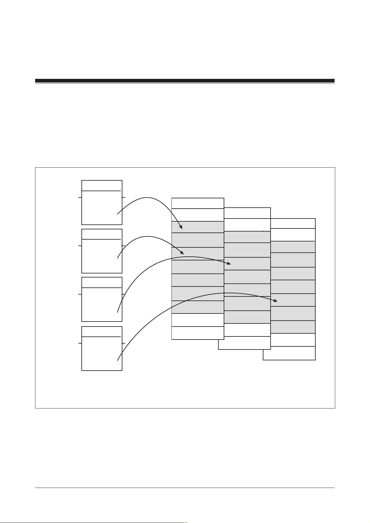
In each of the administration data blocks, the range DW0001 to DW1000
is divided into 5 blocks, each with 200 data words (see Fig. 5-1).
5-3Modular Block System: Emergency Stop Circuits
Page 32
MBS Basics
DB017
DB016
DB015
DW0000
Block 1
200 data words
Block 2
200 data words
Block 3
200 data words
Block 4
200 data words
Block 5
200 data words
Block 6
Global
parameters
DW 0001
to
DW 0200
DW 0201
to
DW 0400
DW 0401
to
DW 0600
DW 0601
to
DW 0800
DW 0801
to
DW 1000
DW 1001
to
DW 1023
5-4
Fig. 5-1: Structure of the administration data blocks
Modular Block System: Emergency Stop Circuits
Page 33

Blocks contained in the administration data blocks
Each standard function block occupies 1 data word per block (see
Fig. 5-2). This means a max. of 200 safety devices (e.g. E-STOP 1, ESTOP 2, safety gate 1) can be managed per administration data block.
The PSS uses a standard function block’s SSNR to automatically generate
the corresponding data words (see section entitled “Input parameter
SSNR”).
DB017
DB016
DB015
DW0000
Block 1
Data word 1
Block 2
Data word 2
Block 3
Data word 3
Block 4
Data word 4
Block 5
Data word 5
Block 6
Global
parameters
Fig. 5-2: Contents of the administration data blocks
Data words 1 to 5
of an MBS
standard function block
5-5Modular Block System: Emergency Stop Circuits
Page 34

MBS Basics
DW0000 (DB015)
1st data block (DB015/DB016/DB017):
DW 0001 ... DW0200 Bits for hardware and operator errors
2nd data block ... 5th data block (DB015/DB016/DB017):
If parameters for a standard function block’s input parameter
SSNR are not within the permitted range, DW0000 of DB015
will contain the incorrect SSNR parameter. The standard
function block will not be enabled (output parameter FG/
ENBL= 0).
If the SSNR=0, DW0000 of DB015 will contain the decimal
value -1 or KH FFFF.
The significance of the individual bits can be found in the
description for the relevant standard function block (see
section entitled “Fault diagnostics”).
If a data word contains the value 0, no error has been found
DW0201 ... DW1000
Data blocks 2 ... 5 are used for internal block data.
6th data block (DB015/DB016/DB017)
DW1001 ... DW1023
Data block 6 contains the global parameters (see section
entitled “Global parameters”).
5-6
Modular Block System: Emergency Stop Circuits
Page 35

Input parameter SSNR
MBS standard function blocks have input and output parameters which
can be adapted to suit the respective control configuration. The input
parameter SSNR (safety subroutine number) is available on all MBS
standard function blocks. It is required to manage the administration data
blocks DB015, DB016 and DB017.
INFORMATION
MBS standard function blocks may differ in terms of the permitted value
range for the SSNR. The following value ranges are possible for the
SSNR:
• Value range of input parameter SSNR: 1 ... 200
(byte constant type: KB001 ... KB200)
• Value range of input parameter SSNR: 1 ... 600
(word constant type: KF000001 ... KF000600)
The valid value range for the SSNR of a standard function block is
documented in the standard function block description.
The input parameter SSNR determines the administration data block plus
the 5 data words assigned in the administration data block of the
corresponding safety device (1 DW per block). The administration data
blocks are assigned the following SSNR ranges:
• SSNR 001 ... 200: DB015
• SSNR 201 ... 400: DB016
• SSNR 401 ... 600: DB017
The one data word per block is generated automatically internally (SSNR +
offset).
5-7Modular Block System: Emergency Stop Circuits
Page 36

MBS Basics
NOTICE
• One MBS standard function block must be used for each safety device.
• Each standard function block should be assigned its own SSNR.
• Make sure that each SSNR is assigned once only.
If two SB calls have the same value for the SSNR, they will access the
same data word in the administration data block. This can lead to
malfunctions.
• Document the assignment of the safety device to the respective SSNR of
the standard function block.
Example
Safety device 2 (E-STOP button) is monitored using SB061. The value
KB002 is assigned to input parameter SSNR of SB061.
The following DWs in DB015 are therefore assigned to safety device 2:
Block 1: DW0002
Block 2: DW0202
Block 3: DW0402
Block 4: DW0602
Block 5: DW0802
The user program has read-only access to these data words.
INFORMATION
On some blocks (e.g. SB061), the input parameter SSNR is monitored.
These blocks must be run through as part of each PSS cycle. The
following commands should therefore be entered once only at the end of
OB 101:
A DB015
I DW1015
Effect:
The counter for monitoring the SSNR in DB015/DW1015 (global
parameters) will be incremented.
5-8
Modular Block System: Emergency Stop Circuits
Page 37

Fault diagnostics
Error types
On programmable safety systems from the PSS-range, a distinction is
made between two types of errors. On the one hand there are errors which
are detected and evaluated through the PSS operating system, and on the
other there are errors which are detected and evaluated through the user
program. The reaction to these two types of errors is different.
Where errors are detected through the operating system, the FS section of
the PSS will switch to a STOP condition and all outputs will be switched off
safely.
Where errors are detected through the user program, only the configured
error reaction will occur. Errors that are detected via an MBS standard
function block belong to this second type of error.
5-9Modular Block System: Emergency Stop Circuits
Page 38
MBS Basics
Fault diagnostics using the administration data blocks
Data words DW0001 ... DW0200 of an administration data block contain
the error messages from the individual MBS standard function blocks (see
Fig 5-3). 1 data word is reserved for each standard function block used.
The assignment is made using the SSNR.
SB061
KB001
KB005
KF000205
KF000427
SSNR
SB061
SSNR
SB065
SSNR
SB065
SSNR
FG
FG
ENBL
ENBL
DB015
DW0000
DW0001
...
DW0005
...
DW0027
...
DW0200
...
DW1023
DB016
DW0000
DW0001
...
DW0005
...
DW0027
...
DW0200
...
DW1023
DB017
DW0000
DW0001
...
DW0005
...
DW0027
...
DW0200
...
DW1023
Fig. 5-3: Managing the MBS error messages using the administration data blocks (example)
5-10
Modular Block System: Emergency Stop Circuits
Page 39

Temporary flag range in MBS blocks
Internally, MBS blocks use the flags in the range M 64.00 ... M69.31 as
temporary flags.
NOTICE
We recommend the following:
• Do not use flags from the temporary flag range for your own applications.
Malfunctions may occur if you use the temporary flag range M64.00 ...
M69.31 for your own applications.
• If it is absolutely necessary to use this flag range, under no
circumstances should you use the flags:
- in alarm OBs
- as input parameters for standard function blocks
- as output parameters for standard function blocks
- as global parameters
Output parameter FG/ENBL
Many standard function blocks have an enable output FG/ENBL. This
output parameter indicates the enable status of a standard function block.
The enable status results from the standard function block’s check of the
inputs.
FG / ENBL = 1: No error found,
FG / ENBL = 0: An error has been found,
function is enabled
function is not enabled.
5-11Modular Block System: Emergency Stop Circuits
Page 40

MBS Basics
Assignment of input and output parameters
Input and output parameters should be assigned in accordance with the
details given in the operating manual.
WARNING!
If several unused output parameters are connected to the same flag,
malfunctions may occur in the standard function blocks. If an unused
output has to be assigned a flag, make sure the output is assigned to a
flag that is not used anywhere else in the program.
Minimum scan time
Most of the timer functions required within the blocks are performed using
cycle counters. This means that almost all the timers are available for use
in applications.
INFORMATION
• If MBS blocks are used, a minimum scan time must always be
entered in the configurator. Empirical values should be used.
• If the error message F-20/06 (error category/error number) appears in
the CPU display, you must amend the minimum scan time appropriately.
This error message indicates that the minimum scan time has been
exceeded. The PSS must not be operated while this error message is
present.
SB070 and SB071 automatically enter the minimum scan time in DW1022
of the administration data blocks. In this way it is automatically available to
the MBS.
INFORMATION
Please note that the times are imprecise. The lack of precision on times is
due to the cyclical processing of the user program. It is determined by the
scan time of the respective user program.
The following is generally valid:
The greater the ratio of time value to scan time, the greater accuracy you
will have with the required times.
5-12
Modular Block System: Emergency Stop Circuits
Page 41

Global parameters
Block 6 (DW1001 ... DW1023) of the administration data blocks contains
global parameters. These are parameters that are valid for several blocks.
For details of which global parameters a standard function block uses,
please refer to the description of the individual standard function blocks.
The data words in block 6 must be initialised when the program is started
(OB120) using SB070/SB071 (INIT_MBS).
The abbreviations in brackets {... : ...} at the end of each data word
correspond to the parameters in SB071. The times that are also specified
within the brackets are empirical values, unless stated otherwise.
DW1001 Number of cycles in the contact synchronisation time between
DW1002 Number of cycles in the feedback loop’s reaction time to a
DW1003 Number of cycles in the contact switchover time between a
2 N/O contacts or 2 N/C contacts (e.g. E-STOP button, reset
key, etc.)
{CoSy : 50 ms}
change in the PSS output connected to the main contactor
{RFbL : 100 ms}
N/O and N/C contact (pushbutton)
{CS_B : 100 ms}
DW1004 Number of cycles in the contact switchover time between a
N/O and N/C contact (relay)
{CS_R: 50 ms}
DW1005 Number of cycles in the machine clock time
{MaCy : max. 30 s in accordance with EN 61496-1 section
A.8.4, 06/98}
DW1006 Number of cycles in the permitted ESPE reaction time
{ESPE : max. 150 ms in accordance with EN 61496-1 section
5.2.4, 06/98}
DW1007 Reserved
DW1009 Reserved
DW1010 Reserved
DW1011 Reserved
DW1012 Reserved
DW1013 Reserved
5-13Modular Block System: Emergency Stop Circuits
Page 42

MBS Basics
DW1014 Reserved
DW1015 Counter for monitoring the SSNR
DW1016 Reserved
DW1017 Reserved
DW1018 Reserved
DW1019 Reserved for administration
DW1020 Reserved
DW1021 Reserved for burner management
DW1022 Min. scan time from DB002/DW0002
DW1023 Reserved
5-14
Modular Block System: Emergency Stop Circuits
Page 43

Standard Function Blocks
Guidelines for selecting standard function blocks
Several standard function blocks are available for the following safety
devices:
• E-STOP button
• Feedback loop
• Initialisation of the administration data blocks
The following information is designed to help you select the standard
function block that is most appropriate for your application.
Emergency stop monitoring
SB060 NA_KAT_2
SB060 is designed to monitor single-channel E-STOP buttons in
applications up to category 2.
The additional commands for monitoring the SSNR are required (A
DB015, I DW1015). Further information is available in Chapter 5, in the
section entitled “Input parameter SSNR”.
SB061 NA_1
SB061 is used in applications up to category 4. This standard function
block has no parameter to evaluate the status of I/O-Groups
(SafetyBUS p).
INFORMATION
Do not use SB061 in applications with SafetyBUS p.
SB061 cannot be used to monitor whether contacts switch synchronously
when releasing an E-STOP button that has been operated.
The additional commands for monitoring the SSNR are required
(A DB015, I DW1015). Further information is available in Chapter 5, in the
section entitled “Input parameter SSNR”.
6-1Modular Block System: Emergency Stop Circuits
Page 44

Standard Function Blocks
SB062 E-STOP
SB062 is used in applications up to category 4. This standard function
block is suitable for applications with SafetyBUS p. It has an input
parameter to evaluate the status of the I/O-Group (SafetyBUS p), for which
parameters are set on the E-STOP button contacts.
The run time for SB062 in comparison with SB061 has been optimised so
that SB062 is suitable for use in time-critical or very extensive applications
(even without SafetyBUS p).
It is possible to monitor whether contacts switch synchronously when
releasing an E-STOP button that has been operated. SB062 provides an
additional input parameter for this task.
The additional commands for monitoring the SSNR are not required.
SB063 E-STOP
SB063 is used in applications up to category 4. The function range of
SB063 corresponds largely to that of SB062. However, the value range for
the safety subroutine number SSNR has been expanded to 1...600 (see
Chapter 5, section entitled “Input parameter SSNR”).
The use of SB063 is preferred in very extensive applications (> 200
standard function blocks). In this case, a fast PSS-CPU (e.g. CPU 3) is
also preferable.
The additional commands for monitoring the SSNR are not required.
6-2
Modular Block System: Emergency Stop Circuits
Page 45

Feedback loop monitoring
SB067 RFK_K4
SB067 is used in applications up to category 4. This standard function
block has no parameter to evaluate the status of I/O-Groups
(SafetyBUS p).
INFORMATION
Do not use SB067 in applications with SafetyBUS p.
In applications with SafetyBUS p, use SB065 instead.
SB065 FBL
SB065 is used in applications up to category 4. The function range of
SB065 corresponds largely to that of SB067. However, the value range for
the safety subroutine number SSNR has been expanded to 1...600 (see
Chapter 5, section entitled “Input parameter SSNR”).
Other changes compared with SB067:
• Additional input parameter to set the time for monitoring the feedback
loop individually
• Additional output parameter to drive 2 contactors
• Improved error message output
This standard function block is suitable for applications with SafetyBUS p.
It has an input parameter to evaluate the status of the I/O-Group
(SafetyBUS p), for which parameters are set on the feedback loop
contacts.
The use of SB065 is preferred in the following applications:
• Applications with SafetyBUS p
• Very extensive applications (> 200 standard function blocks) with/without
SafetyBUS p
In this case, a fast PSS-CPU (e.g. CPU 3) is also preferable.
6-3Modular Block System: Emergency Stop Circuits
Page 46

Standard Function Blocks
Initialisation of administration data blocks
SB070 INIT_MBS
SB070 exclusively initialises administration data block DB015 with global
parameters. For this reason it can only be used in applications which:
• Comprise a maximum of 200 standard function blocks
• Do not use standard function blocks SB063, SB064 and SB065
SB071 INIT_MBS
SB071 initialises all three administration data blocks (DB015, DB016 and
DB017) with global parameters. It can be used for all applications.
NOTICE
SB071 is essential if you are using any one of the following standard
function blocks:
• SB063
• SB064
• SB065
In this case, the use of SB071 is firmly specified.
6-4
Modular Block System: Emergency Stop Circuits
Page 47

Notes
6-5Modular Block System: Emergency Stop Circuits
Page 48

Standard Function Blocks
SB060: Emergency stop monitoring, category 2
SB060
Block header
Input parameters
•
•
SB 060
NA_Kat_2
B - SSNR
X - EIN
X - S1_Ö
X - QAnf
X - QAut
SSNR
EIN
: Safety subroutine number
Permitted value range: 1 ... 200
Format: Byte constants KB001 ... KB200
(see sections in Chapter 5 entitled “Administration data blocks
DB015, DB016 and DB017” and “Input parameter SSNR”).
: Reset button (N/O contact)
EIN
= 0/1-pulse edge: Reset occurs
FG - X
•
S1_Ö
•
QAnf
•
QAut
: E-STOP N/C contact
: Automatic reset (PSS cold start)
QAnf
= RLO-0 (M 110.00): No reset required.
Cycle: When the PSS is started up (PSS switched
off/on) or cold started (PSS STOP/RUN), the
enable is triggered without an additional reset.
QAnf
= RLO-1 (M 110.01): Reset required.
Cycle: When the PSS is started up (PSS switched
off/on) or cold started (PSS STOP/RUN), a reset
is required through the input parameter
order to trigger the enable.
: Automatic reset when E-STOP button is released
QAut
= RLO-0 (M 110.00): Reset through input parameter
is required.
QAut
= RLO-1 (M 110.01): Automatic reset when E-STOP is
released. The value of input parameter
irrelevant.
EIN
EIN
in
EIN
is
6-6
Modular Block System: Emergency Stop Circuits
Page 49

Output parameters
•
FG
Error messages
Any fault that is detected will be stored in the corresponding error data
word (
with.
• Error messages in DB015
- Bit 09: E-STOP button operated
- Bit 14: Reset button pressed constantly (i.e. stuck in)
: Enable flag bit
FG
= 0: Not enabled
FG
= 1: Function enabled when no errors are present
SSNR
) of DB 015 (1st data block), until the fault has been fully dealt
Remedy: Check button, cable and input card, release E-STOP
button and reset (input parameter
Remedy: Check button, cable and input card, release E-STOP
button and reset again (input parameter
EIN
)
EIN
)
- Bit 15: E-STOP released, ready for reset.
Remedy: Press reset button (input parameter
• Error messages on the CPU-display
- E 001: Parameter error
SSNR
does not lie within the limits of 1 ... 200
- E 002: Parameter error
SSNR
assigned more than once OR
DW1015 in DB015 was not incremented
EIN
)
Modular Block System: Emergency Stop Circuits 6-7
Page 50

Standard Function Blocks
Global parameters used in administration data block DB 015
Global parameters may be set with SB070 in OB120.
• DW1015: Counter for monitoring the
INFORMATION
On some blocks (e.g. E-STOP) the input parameter
These blocks must be run through as part of each PSS-cycle. The
following commands should therefore be entered once only at the end of
OB101:
A DB015
I DW1015
Effect:
The counter for monitoring the
parameters) will be incremented.
SSNR
SSNR
in DB015/DW1015 (global
SSNR
SB060
is monitored.
Blocks required
• DB015: Administration data block
DB015 must consist of its total length of 1024 data words.
DB015 must have READ/WRITE access.
• SB070 Initialisation of global parameters in DB 015
• SB255: To call up the operating system
6-8
Modular Block System: Emergency Stop Circuits
Page 51

Notes
Modular Block System: Emergency Stop Circuits 6-9
Page 52

Standard Function Blocks
SB061: Emergency stop monitoring, category 4
SB061
Block header
Input parameters
•
•
B - SSNR
X - EIN
X - S1_Ö
X - S2_Ö
X - QAnf
X - QAut
SSNR
EIN
: Safety subroutine number
Permitted value range: 1 ... 200
Format: Byte constants KB001 ... KB200
(see sections in Chapter 5 entitled “Administration data blocks
DB015, DB016 and DB017” and “Input parameter SSNR”).
: Reset button (N/O contact)
EIN
= 0/1-pulse edge: Reset occurs
SB 061
NA_1
FG - X
6-10
•
S1_Ö
•
S2_Ö
•
QAnf
•
QAut
: E-STOP N/C contact 1
: E-STOP N/C contact 2
: Automatic reset (PSS cold start)
QAnf
= RLO-0 (M 110.00): No reset required.
Cycle: When the PSS is started up or cold started,
the enable is triggered without an additional reset.
QAnf
= RLO-1 (M 110.01): Reset required.
Cycle: When the PSS is started up or cold
started, a reset is required through the input
parameter
: Automatic reset when E-STOP button is released
QAut
= 0: Reset through input parameter
EIN
in order to trigger the enable.
EIN
is required.
Modular Block System: Emergency Stop Circuits
Page 53

Output parameters
•
FG
QAut
EIN
QAnf
INFORMATION
Automatic reset is only possible in conjunction with:
EIN
QAnf
This means that an automatic reset
(
(
: Enable flag bit
FG
FG
= 1: Automatic reset when
= 1: E-STOP-button is released
= 0:
= RLO-1 (M 110.01) and
= RLO-0 (M 110.00).
QAut
= 1) and a reset on PSS start-up
QAnf
= 1) are mutually exclusive.
= 0: Not enabled
= 1: Function enabled when no errors are present
Error messages
Any fault that is detected will be stored in the corresponding error data
word (
with.
• Error messages in DB 015
SSNR
- Bit 00: E-STOP button operated
- Bit 01: Contact synchronisation time exceeded for N/C contact
- Bit 02: Contact synchronisation time exceeded for N/C contact
) of DB 015 (1st data block), until the fault has been fully dealt
Remedy: Check button, cable and input card, release E-STOP
button and reset (input parameter
Remedy: Check button, cable and input card, release E-STOP
button and reset (input parameter
Remedy: Check button, cable and input card, release E-STOP
button and reset (input parameter
EIN
EIN
EIN
)
)
)
S1_Ö
S2_Ö
Modular Block System: Emergency Stop Circuits 6-11
Page 54

Standard Function Blocks
- Bit 03: With: “Automatic reset (PSS cold start)”:
E-STOP button operated and reset button pressed
Remedy: Check button, cable and input card, release E-STOP
button and reset again (input parameter
With: “Automatic reset when E-STOP button is released”:
E-STOP button operated
Remedy: Release E-STOP button
- Bit 08: E-STOP released, ready for reset
Remedy: Press reset button (input parameter
- Bit 09: Reset button pressed constantly (i.e. stuck in)
Remedy: Check button, cable and input card, release E-STOP
button and reset again (input parameter
- Bit 10: Reset successful, but N/C contact S1_Ö failed to open when
the E-STOP button was operated.
Remedy: Press E-STOP button again to ensure that contacts
open correctly and then reset; otherwise: check cable and
input card, release the E-STOP button and reset (input
parameter
EIN
SB061
EIN
).
EIN
)
EIN
)
)
- Bit 11: Reset successful, but N/C contact S2_Ö failed to open when
the E-STOP button was operated.
Remedy: Press E-STOP button again to ensure that contacts
open correctly and then reset; otherwise: check cable and
input card, release the E-STOP button and reset (input
parameter
• Error messages on the CPU-display
- E 001: Parameter error
SSNR
EIN
)
does not lie within the limits of 1 ... 200
6-12
Modular Block System: Emergency Stop Circuits
Page 55

- E 002: Parameter error
SSNR
assigned more than once OR
DW1015 in DB015 was not incremented
Global parameters used in administration data block DB015
Global parameters may be set with SB070 in OB120.
• DW1001: Number of cycles in the contact synchronisation time between
the 2 N/C contacts on the E-STOP button
Blocks required
• DW1015: Counter for monitoring the
SSNR
INFORMATION
On some blocks (e.g. E-STOP) the input parameter
SSNR
is monitored.
These blocks must be run through as part of each PSS-cycle. The
following commands should therefore be entered once only at the end of
OB101:
A DB015
I DW1015
Effect:
The counter for monitoring the
SSNR
in DB015/DW1015 (global
parameters) will be incremented.
• DB015: Administration data block
DB015 must consist of its total length of 1024 data words.
DB015 must have READ/WRITE access.
• SB070 Initialisation of global parameters in DB015
• SB255: To call up the operating system
Modular Block System: Emergency Stop Circuits 6-13
Page 56

Standard Function Blocks
SB062: Emergency stop monitoring, category 4
SB062
Block header
Input parameters
•
SSSNR
SB062
E-STOP
B - SSNR
X - GRP
X - RSET
X - NC_1
X - NC_2
X - AuST
X - ARst
X - FTST
: Safety subroutine number
Permitted value range: 1 ... 200
Format: Byte constants KB001 ... KB200
(see sections in Chapter 5 entitled “Administration data blocks
DB015, DB016 and DB017” and “Input parameter SSNR”).
ENBL - X
•
GRP:
•
RSET:
•
NC_1:
•
NC_2:
•
AuSt:
On SafetyBUS p applications:
Assign the status flag of the I/O-Group containing inputs
and
NC_
2 (M 116.00 for I/O-Group 0 to M 116.31 for I/OGroup 31).
On non-SafetyBUS p applications:
Assign RLO-1 (M 110.01)
Reset button (N/O contact)
RSET
E-STOP N/C contact 1
E-STOP N/C contact 2
Reset on start-up (PSS cold start) or when I/O-Group is
started (SafetyBUS p)
AuST
Sequence: When the PSS is powered up or cold started or the
I/O-Group is started (GRP = 0/1-pulse edge), an initial reset is
required through input parameter
enable.
= 0/1-pulse edge: Reset occurs
= RLO-0 (M 110.00): Initial reset required.
RSET
, in order to trigger the
NC_1
6-14
Modular Block System: Emergency Stop Circuits
Page 57

•
ARst:
•
FTST
Output parameters
•
ENBL:
AuSt
= RLO-1 (M 110.01): No initial reset required.
Sequence: When the PSS is powered up or cold started or the
I/O-Group is started (GRP = 0/1-pulse edge), the enable is
triggered without a further reset.
also required in order to set the enable.
Automatic reset when E-STOP button is released
ARst
= RLO-0 (M 110.00): Reset through input parameter
RSET
ARst
STOP button is released
Function test
FTST
FTST
if a synchronisation error occurs when the E-STOP button
is released.
Enable flag bit
ENBL
ENBL
is required
= RLO-1 (M 110.01): Automatic reset required when E-
= RLO-0 (M 110.00): No function test required
= RLO-1 (M 110.01): A function test must be performed
= 0: Enable is blocked
= 1: This function is error-free, the E-STOP button
has not been operated
NC_1
= 1 and
NC_2
= 1 is
Function test
Input parameter
test is required if a synchronisation error occurs when the E-STOP button
is released.
Irrespective of parameter
if a synchronisation error occurs when the E-STOP button is operated.
The function test will check whether both contacts on the E-STOP button
are switching synchronously.
Sequence of function test:
• Press E-STOP button
• Release E-STOP button
• Press reset button (input parameter
Modular Block System: Emergency Stop Circuits 6-15
FTST
can be used to establish whether or not a function
FTST
, a function test must always be performed
RSET
)
Page 58

Standard Function Blocks
Error messages
Any fault that is detected will be stored in the corresponding error data
word (
with.
• Error messages in DB015
SSNR
- Bit 00: E-STOP button operated
- Bit 01: Reset required
- Bit 03: Function test required due to a synchronisation error
- Bit 04: E-STOP button operated and reset button pressed
) of DB015 (1st data block), until the fault has been fully dealt
Remedy: Release E-STOP button and reset
(input parameter
Remedy: Reset (input parameter
Remedy: Perform function test (press E-STOP button, release
it and reset (input parameter
Remedy: Check button, cable and input card, release E-STOP
button and reset again (input parameter
RSET
SB062
)
RSET
RSET
))
)
RSET
)
- Bit 05: Reset button pressed too soon or constantly pressed
Remedy: Check reset button, cable and input card and reset
again (input parameter
- Bit 06: Initial reset required
Remedy: Reset (input parameter
- Bit 07: Synchronisation error N/C contact 1
Remedy: Check button, cable and input card, release the ESTOP button and perform a function test (press E-STOP
button, release it and reset (input parameter
- Bit 08: Synchronisation error N/C contact 2
Remedy: Check button, cable and input card, release the ESTOP button and perform a function test (press E-STOP
button, release it and reset (input parameter
- Bit 09: I/O-Group stop triggered while PSS is in RUN mode
Remedy: Start I/O-Group
RSET
)
RSET
)
RSET
RSET
))
))
6-16
Modular Block System: Emergency Stop Circuits
Page 59

• Error messages on the CPU-display
- None
Global parameters used in administration data block DB015
The global parameter may be set in OB120 using SB070.
• DW1001: Number of cycles in the contact synchronisation time between
the 2 N/C contacts on the E-STOP button
Blocks required
• DB015: Administration data block
DB015 must consist of its total length of 1024 data words.
DB015 must have READ/WRITE access.
• SB070: Initialisation of global parameters in DB015
Modular Block System: Emergency Stop Circuits 6-17
Page 60

Standard Function Blocks
SB063: Emergency stop monitoring, category 4
SB063
Block header
Input parameters
•
SSNR
SB063
E-STOP
W - SSNR
X - GRP
X - NC_1
X - NC_2
X - AuSt
X - ARSt
X - FTST
X - RSET
: Safety subroutine number
Permitted value range: 1 ... 600
Format: Word constants KF000001 ... KF000600
(see sections in Chapter 5 entitled “Administration data blocks
DB015, DB016 and DB017” and “Input parameter SSNR”).
ENBL - X
•
GRP:
•
NC_1:
•
NC_2:
•
AuSt:
I/O-Group status flag (SafetyBUS p) containing the inputs
NC_1
and
NC_2
I/O-Group 31)
If the SB is being used without SafetyBUS p, the input
parameter must be assigned RLO-1.
E-STOP N/C contact 1
E-STOP N/C contact 2
Reset on start-up (PSS cold start) or when I/O-Group is started
(SafetyBUS p)
AuSt
= 0: Initial reset required.
Sequence: When the PSS is cold/warm started or the I/OGroup is started (
required through input parameter
enable.
(M116.00 for I/O-Group 0 to M116.31 for
GRP
= 0/1-pulse edge), an initial reset is
RSET
, in order to trigger the
6-18 Modular Block System: Emergency Stop Circuits
Page 61

•
ARSt:
•
FTST
•
RSET:
AuSt
= 1: No initial reset required
Sequence: When the PSS is cold/warm started or the I/OGroup is started (GRP = 0/1-pulse edge), the enable is
triggered without a further initial reset.
is also required in order to set the enable.
Automatic reset when E-STOP button is released
ARSt
= 0: Reset through input parameter
ARSt
= 1: Automatic reset required when E-STOP button is
released
Function test
FTST
= 0: No function test required
FTST
= 1: A function test must be performed if a
synchronisation error occurs when the E-STOP button is
released.
Reset button (N/O contact)
RSET
RSET should be assigned RLO-0 if you do not need a reset
button (e.g. with automatic reset).
= 0/1-pulse edge: Reset occurs
NC_1
RSET
= 1 und
is required
NC_2
= 1
Output parameters
•
ENBL:
Function test
The function test will check whether both contacts on the E-STOP button
are switching synchronously.
A function test must always be performed if a synchronisation error occurs
when the E-STOP button is operated.
Input parameter
test is required if a synchronisation error occurs when the E-STOP button
is released.
Enable bit
ENBL
ENBL
= 0: Enable is blocked
= 1: This function is error-free, the E-STOP button
FTST
has not been operated
can be used to establish whether or not a function
Modular Block System: Emergency Stop Circuits 6-19
Page 62

Standard Function Blocks
Sequence of function test:
• Press E-STOP button
• Release E-STOP button
SB063
Error messages
• Press reset button (input parameter
Any fault that is detected will be stored in the corresponding error data
word (
fault has been fully dealt with.
• Error messages in the administration data block
SSNR
- Bit 00: E-STOP button operated
- Bit 01: Reset required
- Bit 03: Function test required due to a synchronisation error
- Bit 04: E-STOP button operated and reset button pressed
) of the administration data block (1st data block), until the
Remedy: Release E-STOP button and reset
(input parameter
Remedy: Reset (input parameter
Remedy: Perform function test (press E-STOP button, release
it and reset (input parameter
Remedy: Check button, cable and input card, release E-STOP
button and reset again (input parameter
RSET
)
RSET
RSET
)
RSET
))
)
RSET
)
- Bit 05: Reset button pressed too soon or constantly pressed
Remedy: Check reset button, cable and input card and reset
again (input parameter
- Bit 06: Initial reset required
Remedy: Reset (input parameter
- Bit 07: Synchronisation error N/C contact 1
Remedy: Check button, cable and input card, release the ESTOP button and perform a function test (press E-STOP
button, release it and reset (input parameter
6-20 Modular Block System: Emergency Stop Circuits
RSET
)
RSET
)
RSET
))
Page 63

- Bit 08: Synchronisation error N/C contact 2
Remedy: Check button, cable and input card, release the ESTOP button and perform a function test (press E-STOP
button, release it and reset (input parameter
- Bit 09: I/O-Group stop triggered while PSS is in RUN mode
Remedy: Start I/O-Group
• Error messages on the CPU-display
- E003 Administration data block has not been initialised
Remedy: Call SB071 in OB120
Global parameters used in the administration data blocks
The global parameter may be set in OB120 using SB071.
• DW1001: Number of cycles in the contact synchronisation time between
the 2 N/C contacts on the E-STOP button
Blocks required
RSET
))
• DB015, DB016, DB017: Administration data blocks
The data blocks must consist of their total length of 1024 data
words and have READ/WRITE access (see Chapter 5, section
entitled “Administration data blocks...”).
• SB071: Initialisation of global parameters in DB015, DB016 and DB017
Modular Block System: Emergency Stop Circuits 6-21
Page 64

Standard Function Blocks
SB065: Feedback loop monitoring
SB065
Block header
Input parameters
•
SSNR
SB065
FBL
W- SSNR
X - GRP
X - ON
X - FbL1
X - FbL2
W- TFbL
X - RSET
: Safety subroutine number
Permitted value range: 1 ... 600
Format: Word constants KF000001 ... KF000600
(see sections in Chapter 5 entitled “Administration data blocks
DB015, DB016 and DB017” and “Input parameter SSNR”).
ENBL - X
K1 - X
K2 - X
•
GRP
: I/O-Group status flag (SafetyBUS p) containing the inputs
FBL1
and
FBL2
(M116.00 for I/O-Group 0 to M116.31 for I/OGroup 31)
If the SB is being used without SafetyBUS p, the input
parameter must be assigned RLO-1
•
ON
: Switch on contactors via output parameters K1 and
ON
= 0/1 pulse edge: Switch on output parameters K1 and
(K1 = 1 and K2 = 1)
ON
= 1/0 pulse edge: Switch off output parameters K1 and
(K1 = 0 and K2 = 0)
•
FbL1
: Feedback loop N/C contact on contactor 1
•
FbL2
: Feedback loop N/C contact on contactor 2
K2
K2
K2
6-22 Modular Block System: Emergency Stop Circuits
Page 65

•
TFbL
: Time for feedback loop monitoring when switching on/off
Permitted value range in ms: 0 ... 2000
When
will be used from DW1002 of the administration data block
(global parameter
Format: Word constants KF000000 ... KF002000
Recommended value: 100 ms (KF000100)
INFORMATION
The value for feedback loop monitoring should be less than the interval
between consecutive operations.
Irrespective of parameter
feedback loops
switching on (ON = 0/1 pulse edge).
•
RSET
: Reset input
RSET
Input circuitry
If you are only using one feedback loop, connect the feedback loop input
to
FbL1
and
TFbL
= 0, the default value for feedback loop monitoring
RFbL
).
TFbL
, the initial acknowledgements from
FbL1
=1 and
= 0/1 pulse edge: trigger reset
FbL2
.
FbL2
= 1 must always be present when
Output parameters
•
ENBL
•K1: Output for driving contactor 1
•K2: Output for driving contactor 2
Output circuitry
If you are only using one contactor, connect the contactor output to K1 and
K2
Modular Block System: Emergency Stop Circuits 6-23
: Enable bit
.
ENBL
ENBL
= 0: Enable is blocked
= 1: Contactors are free from error
Page 66

Standard Function Blocks
Wiring for category 4
If you use two contactors in applications for category 4, please note the
following guidelines when using the various output modules:
• DOS: The contactors must be connected to adjacent blocks of 8
outputs (see “Installation Manual for the PSS 3000/PSS 3100
series”)
• DI2OZ: The contactors may be connected to a dual-pole output.
Connect the contactor output to K1 and K2.
• DI8O8: The contactors must be connected to two different single-pole
outputs in the range O0 to O5. Alternatively, where the outputs
are so configured, the contactors may be connected to a dualpole output O4 or O5 (see “Installation Manual PSS SB
DI8O8”). In this case, connect the contactor output to K1 and
K2
.
SB065
Functions
The contactors can only be switched on when they are in their start
position (
The operation is monitored via acknowledgements from
When switching on and off, acknowledgements must change state within a
maximum reaction time. This reaction time can be set within the range of
0 ... 2000 ms via input parameter
exceeded, an error message will be issued (
will be switched off immediately (K1 = 0 and K2 = 0). The error will need to
be reset.
The time for feedback loop monitoring should be set as short as possible.
When
used from DW1002 of the administration data block (global parameter
RFbL
monitoring should in any case be less than the interval between
consecutive operations.
FbL1
=1 and
TFbL
= 0, the default value for feedback loop monitoring will be
, recommended value: 100 ms). The value for feedback loop
FbL2
= 1).
FbL1
TFbL
. If the maximum reaction time is
ENBL
= 0) and the contactors
and
FbL2
.
6-24 Modular Block System: Emergency Stop Circuits
Page 67

The acknowledgements
condition. If there are discrepancies between the set and true condition, an
error message will be issued (
switched off immediately (K1 = 0 and K2 = 0). The error will need to be
reset.
FbL1
and
ENBL
FbL2
are also monitored in the static
= 0) and the contactors will be
Error messages
It is possible to reset errors via the input parameter
0 and when ON = 1. However, a prerequisite for setting the enable and,
when ON = 1, switching on the contactors, is that the signals from the
feedback loops are correct.
Any fault that is detected will be stored in the corresponding error data
word (
fault has been fully dealt with.
• Error messages in the administration data block
SSNR
- Bit 00: Fault as the signal changes at input parameter
- Bit 01: Fault as the signal changes at input parameter
) of the administration data block (1st data block), until the
feedback loop 1 (
Remedy: Check contactor, contacts, cable, input card, output
card, value of input parameter
then reset (input parameter
feedback loop 1 (
Remedy: Check contactor, contacts, cable, input card, output
card, value of input parameter
then reset (input parameter
FbL1
) remains open
FbL1
) remains closed
TFbL
RSET
TFbL
RSET
)
)
RSET
both when ON =
ON,
and all conditions and
ON,
and all conditions and
- Bit 02: Fault as the signal changes at input parameter
feedback loop 2 (
Remedy: Check contactor, contacts, cable, input card, output
card, value of input parameter
then reset (input parameter
Modular Block System: Emergency Stop Circuits 6-25
FbL2
) remains open
TFbL
RSET
and all conditions and
)
ON,
Page 68

Standard Function Blocks
SB065
- Bit 03: Fault as the signal changes at input parameter
feedback loop 2 (
Remedy: Check contactor, contacts, cable, input card, output
card, value of input parameter
then reset (input parameter
- Bit 04: Fault during the static condition at input parameter
feedback loop 1 (
Remedy: Check contactor, contacts, cable, input card, output
card and all conditions and then reset (input parameter
- Bit 05: Fault during the static condition at input parameter
feedback loop 1 (
Remedy: Check contactor, contacts, cable, input card, output
card and all conditions and then reset (input parameter
- Bit 06: Fault during the static condition at input parameter
feedback loop 2 (
Remedy: Check contactor, contacts, cable, input card, output
card and all conditions and then reset (input parameter
- Bit 07: Fault during the static condition at input parameter
feedback loop 2 (
Remedy: Check contactor, contacts, cable, input card, output
card and all conditions and then reset (input parameter
FbL2
) remains closed
FbL1
) interrupted
FbL1
) closed
FbL2
) interrupted
FbL2
) closed
TFbL
RSET
and all conditions and
)
ON,
ON,
ON,
ON,
ON,
RSET
RSET
RSET
RSET
)
)
)
)
- Bit 08: Reset input constantly 1 or set too early
Remedy: Release reset button and press again, otherwise:
check switch, cable and input card and reset again (input
parameter
- Bit 09: I/O-Group stop triggered while PSS is in normal RUN mode
Remedy: Start I/O-Group
• Error messages on the CPU-display
- E003: Administration data block has not been initialised
Remedy: Call SB071 in OB120
RSET
)
6-26 Modular Block System: Emergency Stop Circuits
Page 69

Global parameters used in the administration data blocks
Global parameters may be set in OB120 using SB071.
• DW1002: Number of cycles for the reaction time of the feedback loop
with contactors
• DW1022: Minimum scan time
Blocks required
• DB015, DB016, DB017: Administration data blocks
The data blocks must consist of their total length of 1024 data
words and have READ/WRITE access (see Chapter 5, section
entitled “Administration data blocks...”).
• SB071: Initialisation of global parameters in DB015, DB016 and DB017
Modular Block System: Emergency Stop Circuits 6-27
Page 70

Standard Function Blocks
SB067: Feedback loop monitoring
SB067
Block header
Input parameters
•
•
•
SSNR
RFK1
RFK2
SB 067
RFK_K4
B - SSNR
X - RFK1
X - RFK2
X - RSET
X - Ein
: Safety subroutine number
Permitted value range: 1 ... 200
Format: Byte constants KB001 ... KB200
(see sections in Chapter 5 entitled “Administration data blocks
DB015, DB016 and DB017” and “Input parameter SSNR”).
: Feedback loop N/C contact on contactor 1
: Feedback loop N/C contact on contactor 2
FG - X
K- X
•
RSET
•
Ein
Input circuitry
If you are only using one feedback loop, connect the RFK input to
and
Output parameters
•
FG
•K: Output to main contactor
: Reset input
RSET
: Switches on main contactor via output parameter
Ein
Ein
RFK2
.
: Enable bit
FG
FG
= 0/1 signal edge: Trigger reset
= 0/1-signal edge: Switch on output parameter K (K = 1)
= 1/0-signal edge: Switch off output parameter K (K = 0)
= 0: Not enabled
= 1: No error found on this relay block function
K
RFK1
6-28
Modular Block System: Emergency Stop Circuits
Page 71

Error messages
Any fault that is detected will be stored in the corresponding error data
word (
with.
• Error messages in DB015
SSNR
- Bit 00: Faults which occur as the pulse edge changes at the input
- Bit 01: Faults which occur as the pulse edge changes at the input
- Bit 02: Faults which occur as the pulse edge changes at the input
) of DB015 (1st data block), until the fault has been fully dealt
parameter
RFK 1 remains open
Remedy: Check contacts, cable, input card and all conditions
and then reset (input parameter
parameter
RFK 1 remains closed
Remedy: Check contacts, cable, input card and all conditions
and then reset (input parameter
parameter
RFK 2 remains open
Remedy: Check contacts, cable, input card and all conditions
and then reset (input parameter
EIN
EIN
EIN
RSET
RSET
RSET
)
)
)
- Bit 03: Faults which occur as the pulse edge changes at the input
parameter
RFK 2 remains closed
Remedy: Check contacts, cable, input card and all conditions
and then reset (input parameter
- Bit 04: Faults which occur as the pulse edge changes at the input
parameter
RFK 1 interrupted
Remedy: Check contacts, cable, input card and all conditions
and then reset (input parameter
- Bit 05: Faults which occur as the pulse edge changes at the input
parameter
RFK 1 closed
Remedy: Check contacts, cable, input card and all conditions
and then reset (input parameter
EIN
EIN
EIN
RSET
RSET
RSET
)
)
)
Modular Block System: Emergency Stop Circuits 6-29
Page 72

Standard Function Blocks
- Bit 06: Faults which occur as the pulse edge changes at the input
parameter
Faults which occur as the pulse edge changes at the inputRFK
2 interrupted
Remedy: Check contacts, cable, input card and all conditions
and then reset (input parameter
- Bit 07: Faults which occur as the pulse edge changes at the input
parameter
RFK 2 closed
Remedy: Check contacts, cable, input card and all conditions
and then reset (input parameter
- Bit 08: Faults which occur as the pulse edge changes at the input
parameter
Reset input constantly high or set too early
Remedy: Release reset button and press it again. If this does
not work, check contacts, cable, input card and all conditions
and then reset (input parameter
EIN
EIN
EIN
RSET
RSET
RSET
SB067
)
)
)
• Error messages on the CPU-display
- None
Global parameters used in administration data block DB015
Global parameters may be set in OB120 using SB070.
• DW1002: Number of cycles for reaction time of RFK
Blocks required
• DB015: Administration data block
DB015 must consist of its total length of 1024 data words.
DB015 must have READ/WRITE access.
• SB070 Initialisation of global parameters in DB015
6-30
Modular Block System: Emergency Stop Circuits
Page 73

Notes
Modular Block System: Emergency Stop Circuits 6-31
Page 74

Standard Function Blocks
SB070: Initialisation of administration data block (DB015)
SB070
Block header
Input parameters
•
•
•
SB 070
INIT_MBS
B - KoSy
B - RRFK
B - KU_S
B - KU_R
W - MaZy
B - RBWS
W - RVen
KoSy
: Contact synchronisation time of 2 N/O or N/C contacts
RRFK
KU_S
: Reaction time feedback loop contactor
: Contact switchover time N/O / N/C on buttons
Function
•
KU_R
•
MaZy
•
RBWS
•
RVen
• Reads in the preset minimum scan time from DB002
A minimum scan time must always be configured if you are using MBS
blocks. Please refer to the section entitled “Minimum scan time” in
Chapter 5.
• Calculates the cycles using the times transferred in the parameters
• Enters the values into global parameters DW1001 ... DW1007 of
administration data block DB015.
: Contact switchover time N/O / N/C on relays
: Machine cycle time for cycling ESPE/AOPD
: ESPE/AOPD reaction time
: Valve switchover time
6-32
Modular Block System: Emergency Stop Circuits
Page 75
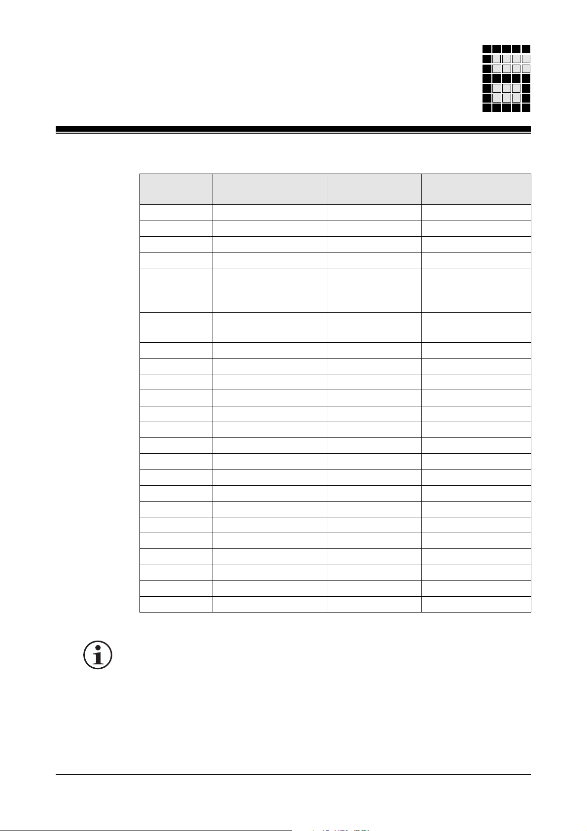
Table for setting the global parameters:
Input Parameters in Limits Suggested
parameters Admin.-DB in [ms] values in [ms]
KoSy DW 1001 0... 255 50
RRFK DW 1002 0... 255 100
KU_S DW 1003 0... 255 100
KU_R DW 1004 0... 255 50
MaZy DW 1005 0... 32 767 30 000, conforming
to EN 61 496-1
A.8.4/C.6.2
RBWS DW 1006 0... 255 150, conforming
to EN 61 496-1
RVen DW 1007 0... 32 767 None
DW 1008
DW 1009
Reserved DW 1010
DW 1011
DW 1012
DW 1013
DW 1014
Reserved DW 1015
DW 1016
DW 1017
DW 1018
DW 1019
Reserved DW 1020
Reserved DW 1021
Reserved DW 1022 Min. scan time DB002/DW0002
Reserved DW 1023
INFORMATION
• All times must be entered in ms.
• The values suggested are default values. If working with these values
produces nuisance errors, you can determine which values would be
suitable as follows:
- Start from the default value
- Increase this value in stages until the nuisance errors stop.
Modular Block System: Emergency Stop Circuits 6-33
Page 76

Standard Function Blocks
Please note:
Entering excessively high time values for monitoring operations will reduce
the safety level of your machine.
If you are using type 2 ESPE/AOPD devices, a maximum value of 150 ms
may be entered for parameter
• The number of cycles calculated is rounded down and transmitted to the
data words in administration data block DB 015.
• The SB must be called up once only when the PSS is started up
(e.g. in OB120).
Error messages
• None
RBWS
SB070
(EN 61 496-1).
Blocks required
• OB120
• DB015: Administration data block
DB015 must consist of its total length of 1024 data words.
DB015 must have READ/WRITE access.
6-34
Modular Block System: Emergency Stop Circuits
Page 77

Notes
Modular Block System: Emergency Stop Circuits 6-35
Page 78

Standard Function Blocks SB071
SB071: Initialisation of administration data blocks
Block header
Input parameters
•
•
•
SB071
INIT_MBS
B - CoSy
B - RFbL
B - CS_B
B - CS_R
W - MaCy
B - ESPE
CoSy
: Contact synchronisation time of 2 N/O or N/C contacts
RFbL
: Reaction time feedback loop contactor
CS_B
: Contact switchover time N/O / N/C on buttons
Function
•
CS_R
•
MaCy
•
ESPE
• Reads in the preset minimum scan time from DB002
A minimum scan time must always be configured if you are using MBS
blocks. Please refer to the section entitled “Minimum scan time” in
Chapter 5.
• Calculates the cycles using the times transferred in the parameters
• Enters the values into global parameters DW1001 ... DW1023 of the
administration data blocks.
: Contact switchover time N/O / N/C on relays
: Machine cycle time for cycling ESPE/AOPD
: ESPE/AOPD reaction time
6-36
Modular Block System: Emergency Stop Circuits
Page 79

Table for setting the global parameters:
Input Parameters in Limits Suggested
parameters Admin.-DB in [ms] values in [ms]
CoSy DW 1001 0... 255 50
RFbL DW 1002 0... 255 100
CS_B DW 1003 0... 255 100
CS_R DW 1004 0... 255 50
MaCy DW 1005 0... 30 000 30 000, conforming
to EN 61 496-1
A.8.4/C.6.2
ESPE DW 1006 0... 255 150, conforming
to EN 61 496-1
Reserved DW 1007
DW 1008
DW 1009
Reserved DW 1010
DW 1011
DW 1012
DW 1013
DW 1014
Reserved DW 1015
DW 1016
DW 1017
DW 1018
Reserved DW 1019 Administration
Reserved DW 1020
Reserved DW 1021
Reserved DW 1022 Min. scan time DB002/DW0002
Reserved DW 1023
INFORMATION
• All times must be entered in ms.
• The values suggested are default values. If working with these values
produces nuisance errors, you can determine which values would be
suitable as follows:
- Start from the default value
- Increase this value in stages until the nuisance errors stop.
Modular Block System: Emergency Stop Circuits 6-37
Page 80

Standard Function Blocks SB071
Please note:
Entering excessively high time values for monitoring operations will reduce
the safety level of your machine.
If you are using type 2 ESPE/AOPD devices, a maximum value of 150 ms
may be entered for parameter
• The number of cycles calculated is rounded down and transmitted to the
data words in the administration data blocks.
• The SB must be called up once only when the PSS is started up
(e.g. in OB120).
Error messages
• None
ESPE
(EN 61 496-1).
Blocks required
• OB120
• DB015/DB016/DB017: Administration data blocks
The data blocks must consist of their total length of 1024 data words.
The data blocks must have READ/WRITE access.
6-38
Modular Block System: Emergency Stop Circuits
Page 81

Link Blocks
Check list
• Safety regulations
• Selecting standard function blocks
- Which safety regulations need to be met?
- Aid: Relevant standards and regulations.
- Which safety devices or process functions need to be supported?
Aid: Consult plant and machinery plans.
- Which standard function blocks should be used?
Aid: Consult sample programs in Chapter 8.
- Is the contact arrangement on the operator elements suitable for the
standard function blocks?
- Does the PSS have the correct I/O arrangement?
• Start up the failsafe section of the programming device
- Enter password.
• Load project into programming device
- Aid: Use “Change Project” from the project menu.
• Import all the blocks you need into the project
- Aid: Use “Import” from the project menu.
• Link the project allocation table to the block allocation table
- Aid: Use “Import” from the project menu.
- Does the allocation table contain all the operands and tags?
Tip: Logic signals may be linked symbolically.
• Adapt the allocation table to the wiring plan
- Adapt the I/Os in the allocation table.
Aid: Allocation table editor.
- Keep reserved flags free (do not use for your own applications).
• Configure system
- Call up the configurator
- Enter the set layout configuration
- Enter the test pulse allocation
- Enter preliminary run times for test purposes.
7-1Modular Block System: Emergency Stop Circuits
Page 82

Link Blocks
• Establish the sequence in which the blocks will be called up
• Create a supervisory (master) block
These can be optimised during commissioning.
- Enter a minimum scan time.
- If test pulses are to be connected to the 3 ms inputs (E x.16 ... E x.31):
Make sure the DI test time is set correctly.
- MBS blocks must be run through as part of each cycle.
- Aid: Flow chart and listing.
- The master block should be either a PB or an FB
(if parameters are required: FB).
- Call up the blocks in the correct sequence and set parameters for them
Assign a different number to each block SSNR (1 ... 600)
°
Document the SSNR you have used
°
If necessary, combine the enable output parameters (
°
suitable groups by means of a logic AND-operation.
- Remember to take into account any links which have already been
made.
- Enter details on the operation of the selected fault indicator
• Import / set up DB015 or DB015/DB016/DB017 in the project
- DB015/DB016/DB017 must always contain 1024 data words
- DB015/DB016/DB017 must have READ/WRITE status
• Create OB120
If necessary, add SB070 or SB071 call.
FG/ENBL
) into
7-2
Modular Block System: Emergency Stop Circuits
Page 83

• Create OB101
- Reset all enable flags (
FG/ENBL
) at the start of the OB or at the start of
the cycle. This way you can be sure that the FG flags are indeed set.
INFORMATION
On some blocks (e.g. E-STOP) the input parameter “SSNR” is monitored
(see the description of the relevant SB in Chapter 6). These blocks must
be run through as part of each PSS cycle. The following commands
should therefore be entered once only at the end of OB101:
DB015 A
DW1015 I
- Call up the E-STOP standard function blocks directly in OB101 or, for
example, global call in an FB.
- Check:
Have all the blocks required for the application been called up?
• Things to note when starting up the program
Tip:
- On start up, the PSS clears all the flag words, outputs, timers and
counters in the FS section. All the necessary constants should
therefore be set when starting up the program.
• Link Project
INFORMATION
- All safety devices should be checked to ensure they operate correctly.
- Short-circuits and open circuits should be simulated.
7-3Modular Block System: Emergency Stop Circuits
Page 84

Link Blocks
Notes
7-4
Modular Block System: Emergency Stop Circuits
Page 85

Examples
Applications and parameters of individual blocks
The following examples are designed to show the application and
parameters of individual standard function blocks.
The voltage supply to the PSS and the reset input E 0.31 are not shown in
the wiring diagrams for the sake of clarity.
Many of the following diagrams state the category for which the circuitry is
designed, in accordance with EN 954-1, 03/97. For details of how this
relates to the corresponding AK requirement class (DIN V 19 250, 05/94),
please refer to the table in the Appendix.
NOTICE
It is important to note that the categories stated refer exclusively to the
PSS circuitry and the parameters set on the SBs.
To achieve the corresponding category throughout the whole system, all
safety-related components/devices (e.g. E-STOP button, safety limit
switch etc.), plus the whole of the application program must be considered
in the assessment (approved SBs do not need to be tested).
Pilz cannot accept responsibility for classifying installations into particular
categories.
8-1Modular Block System: Emergency Stop Circuits
Page 86
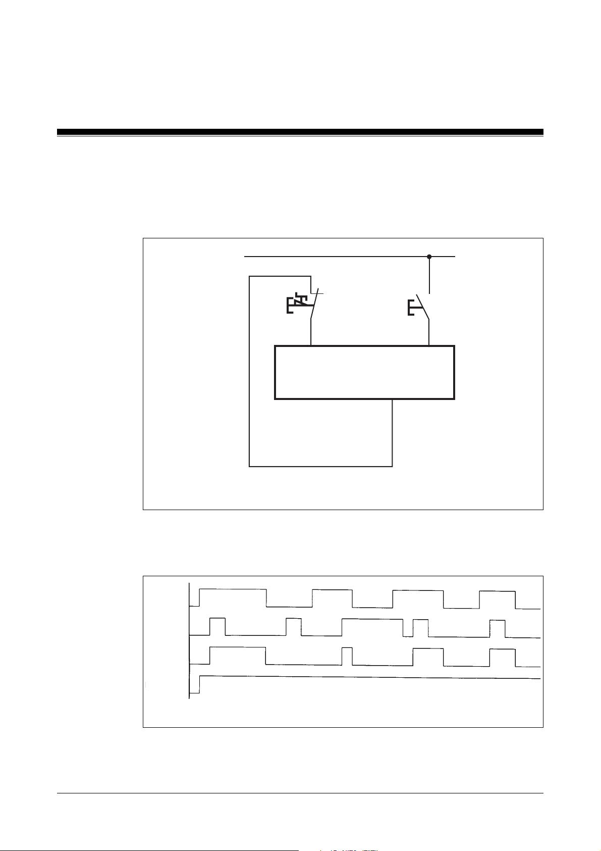
Examples
Emergency stop monitoring with manual start (start-up and operation), category 2
Block used: SB060/NA_Kat_2
24 V
Fig. 8-1: Wiring diagram
E-STOP
E0.01 E0.31
PSS
pulsed output
START
A1.00
8-2
1
E0.01
1
E0.31
1
M70.00
1
PSSSTART
Fig. 8-2: Timing diagram
Modular Block System: Emergency Stop Circuits
Page 87

Program:
SB 060
NA_Kat_2
KB 002 E 0.31 .START E 0.01 .E-STOP M 110.01 .RLO-1 M 110.00 .RLO-0 -
B - SSNR
X - EIN
X - S1_Ö
X - QAnf
X - QAut
FG - X
- M 70.00 .NA_FG
Insert the following additional commands at the end of OB101:
: A DB015
: I DW1015
: BE
8-3Modular Block System: Emergency Stop Circuits
Page 88
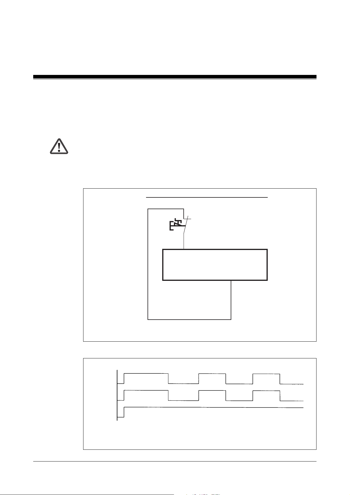
Examples
Emergency stop monitoring with automatic start (start-up and operation), category 2
Block used: SB060/NA_Kat_2
WARNING!
When a safety-related device provides a start or restart signal, the start or
restart shall take place automatically only if a hazardous situation cannot
exist (EN 954).
24 V
E-STOP
Fig. 8-3: Wiring diagram
1
E0.01
1
M70.00
PSSSTART
1
E0.01
PSS
pulsed output
A1.00
8-4
Fig. 8-4: Timing diagram
Modular Block System: Emergency Stop Circuits
Page 89

Program:
SB 060
NA_Kat_2
KB 002 M 110.01 .RLO-1 E 0.01 .E-STOP M 110.00 .RLO-0 M 110.01 .RLO-1 -
B - SSNR
X - EIN
X - S1_Ö
X - QAnf
X - QAut
FG - X
- M 70.00 .NA_FG
Insert the following additional commands at the end of OB101:
: A DB015
: I DW1015
: BE
8-5Modular Block System: Emergency Stop Circuits
Page 90
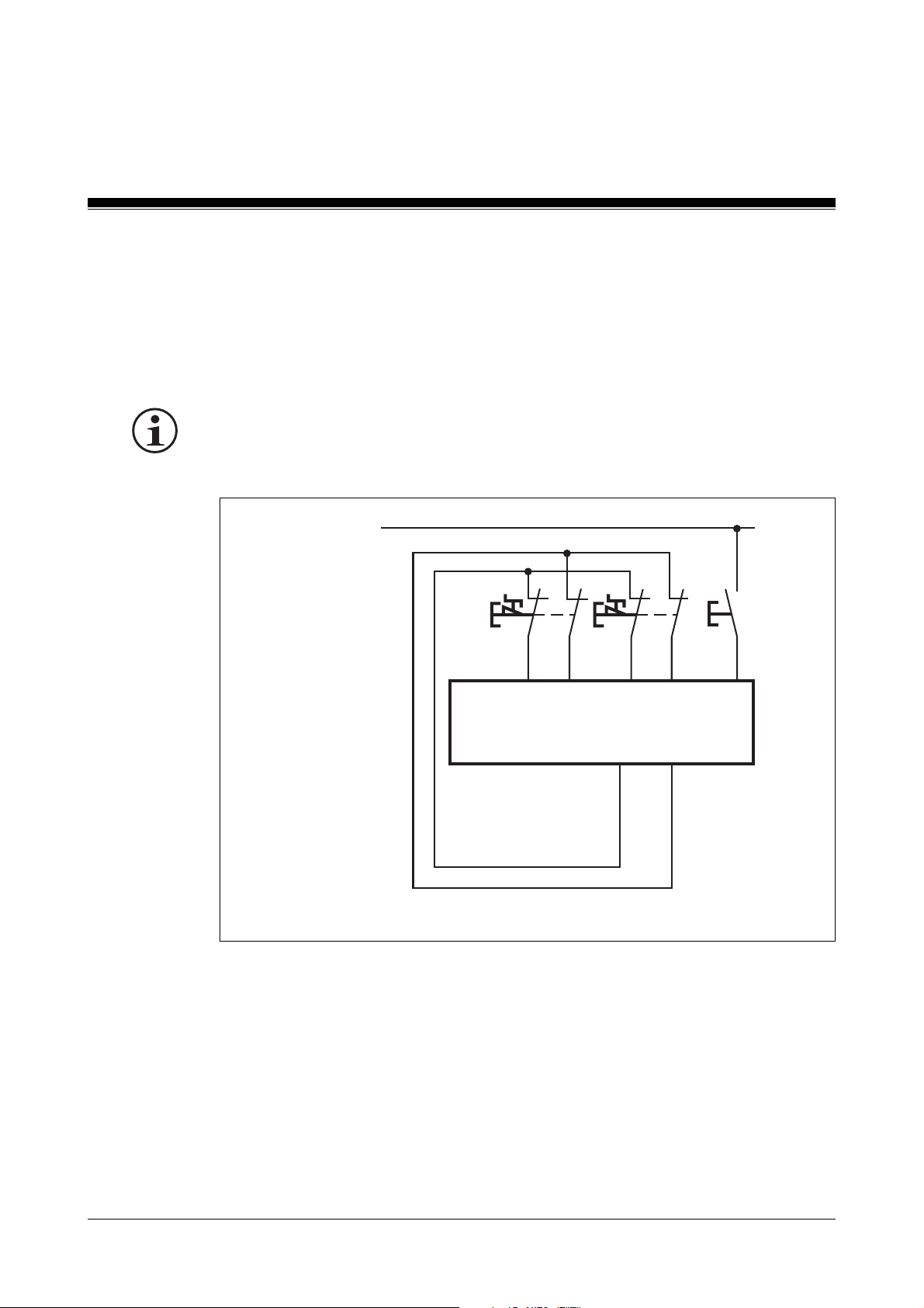
Examples
Emergency stop monitoring with manual start (start-up and operation), category 4
Block used: SB061/NA_1
INFORMATION
• The E-STOP in this example is designed for category 4.
24 V
Fig. 8-5: Wiring diagram
E-STOP 1 2
E0.01
E0.02 E0.03 E0.04 E0.31
PSS
pulsed outputs
START
A1.00 A1.01
8-6
Modular Block System: Emergency Stop Circuits
Page 91
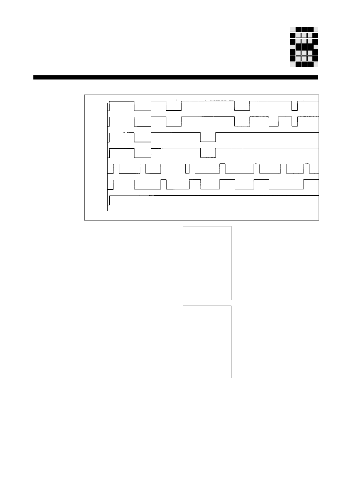
1
E0.01
1
E0.02
1
E0.03
1
E0.04
1
E0.31
1
M80.02
1
PSSSTART
Fig. 8-6: Timing diagram
Program:
SB061
NA_1
KB 003 E 0.31 .START E 0.01 .E-STOP1 E 0.02 .E-STOP1 M 110.01 .RLO-1 M 110.00 .RLO-0 -
B - SSNR
X - EIN
X - S1_Ö
X - S2_Ö
X - QAnf
X - QAut
SB061
NA_1
KB 004 E 0.31 .START E 0.03 .E-STOP2 E 0.04 .E-STOP2 M 110.01 .RLO-1 M 110.00 .RLO-0 -
B - SSNR
X - EIN
X - S1_Ö
X - S2_Ö
X - QAnf
X - QAut
Insert the following additional commands:
: L M80.00 .NA_1
: U M80.01 .NA_2
: = M80.02 .NA_GES
FG - X
FG - X
- M 80.00 .NA_1
- M 80.01 .NA_2
Insert the following additional commands at the end of OB101:
: A DB015
: I DW1015
8-7Modular Block System: Emergency Stop Circuits
Page 92
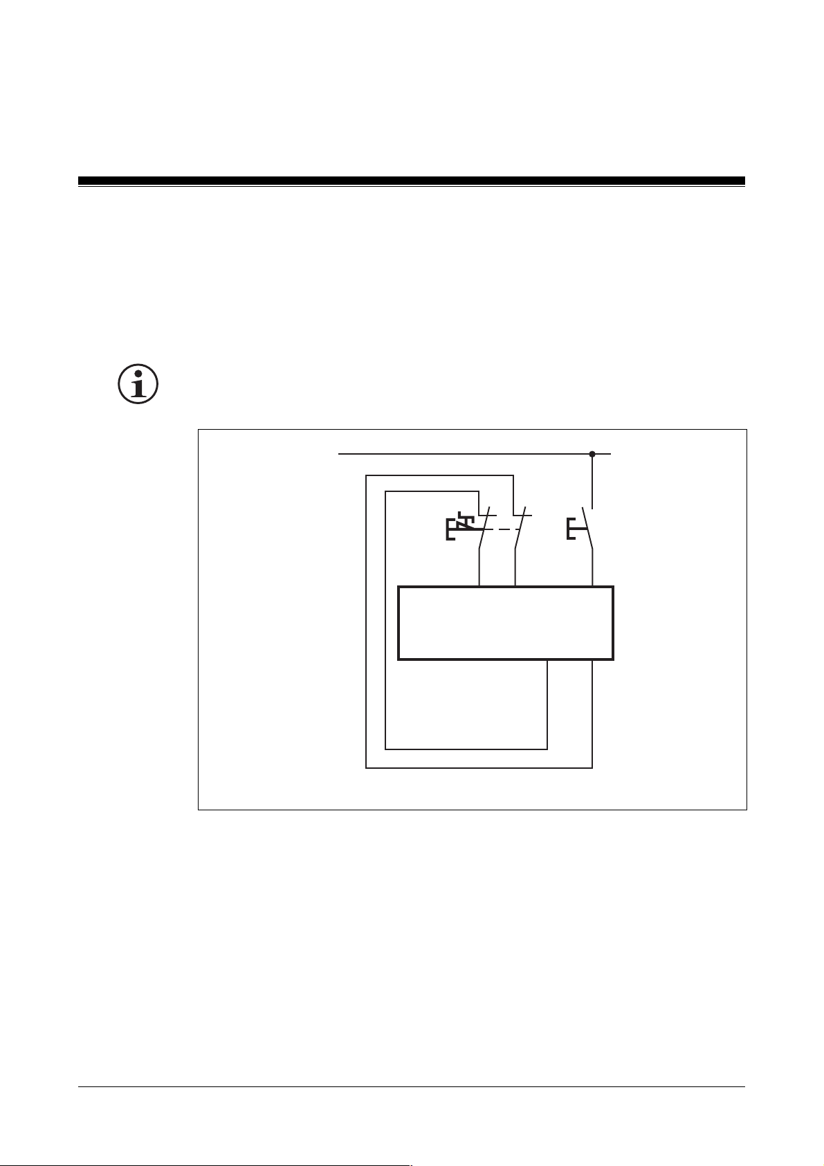
Examples
Emergency stop monitoring with automatic start-up, manual start (operation) and function test, category 4
Block used: SB063/E-STOP
INFORMATION
• The E-STOP in this example is operated to category 4.
24 V
Fig. 8-7: Wiring diagram
E-STOP 1
E40.01
RSET
E40.02 E40.07
PSS
pulsed outputs
T0 T1
8-8
Modular Block System: Emergency Stop Circuits
Page 93
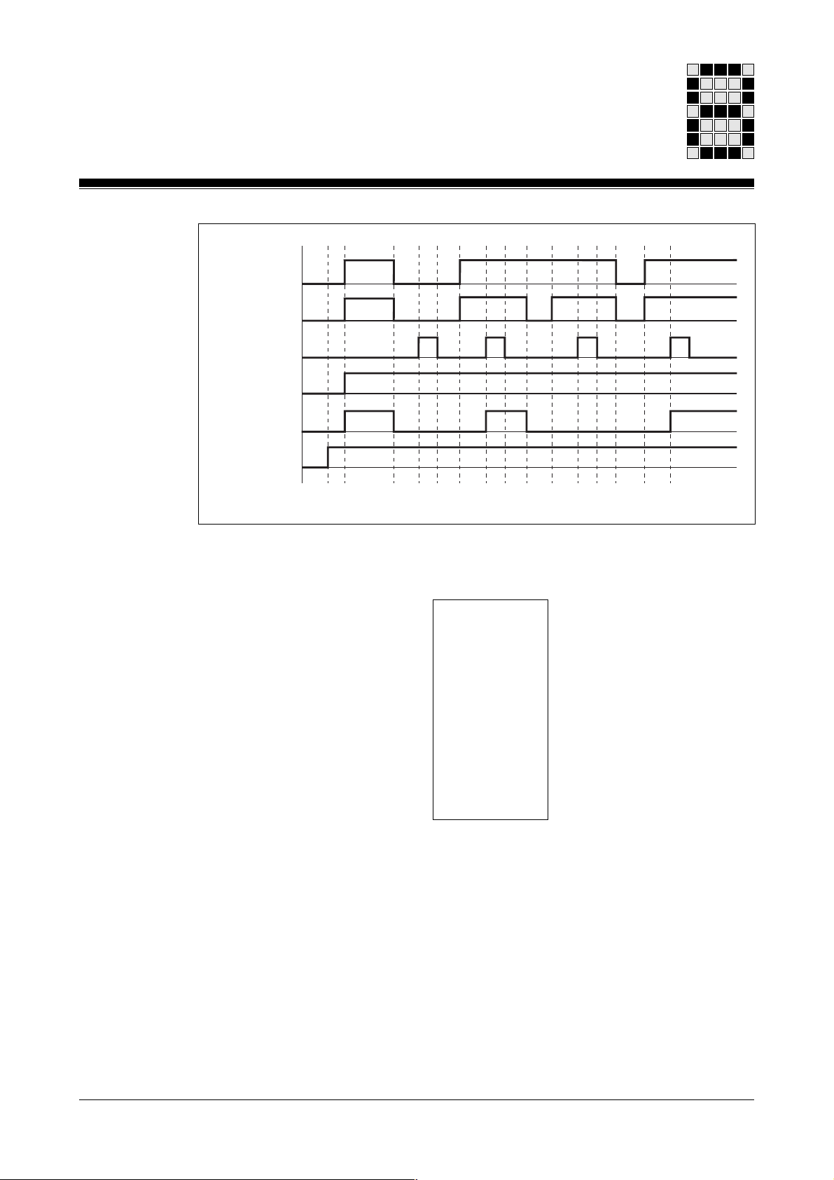
E 40.01
E 40.02
E 40.07
M 116.01
M 80.00
PSS-Start
Fig. 8-8: Timing diagram
Program:
KF 000005 M 116.01 .SBUS_Grp_01
E 40.01 .E-STOP1 E 40.02 .E-STOP1 M 110.01 .RLO-1 M 110.00 .RLO-0 M 110.01 .RLO-1 E 40.07 .Reset -
SB063
E-STOP
W - SSNR
X - GRP
X - NC_1
X - NC_2
X - AuSt
X - ARSt
X - FTST
X - RSET
ENBL - X
- M 80.00 .E-STOP_1
8-9Modular Block System: Emergency Stop Circuits
Page 94
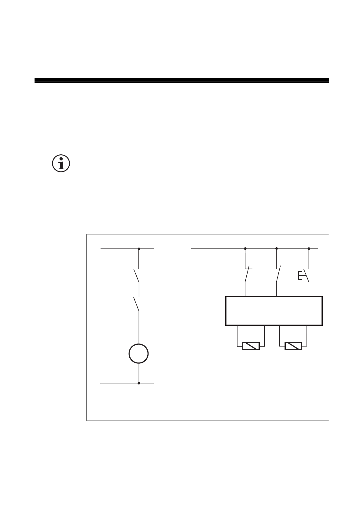
Examples
Feedback loop monitoring (shutdown with two contactors connected in series), category 4
Block used: SB065/FBL
INFORMATION
To achieve category 4, two independent shutdown routes must be
available within the current path of the potentially dangerous drive. This
can be achieved, for example, by connecting two contactors in series.
Please note:
The feedback loops must be wired inside the control cabinet.
L1 24 V
K-M1.1
K-M1.2
M1 M
N
Fig. 8-9: Wiring diagram
FBL
K-M1.1
FBL
K-M1.2
E0.01 E0.02 E0.08
PSS
A1.00
K-M1.1
A1.08
K-M1.2
M1
EIN
8-10
Modular Block System: Emergency Stop Circuits
Page 95
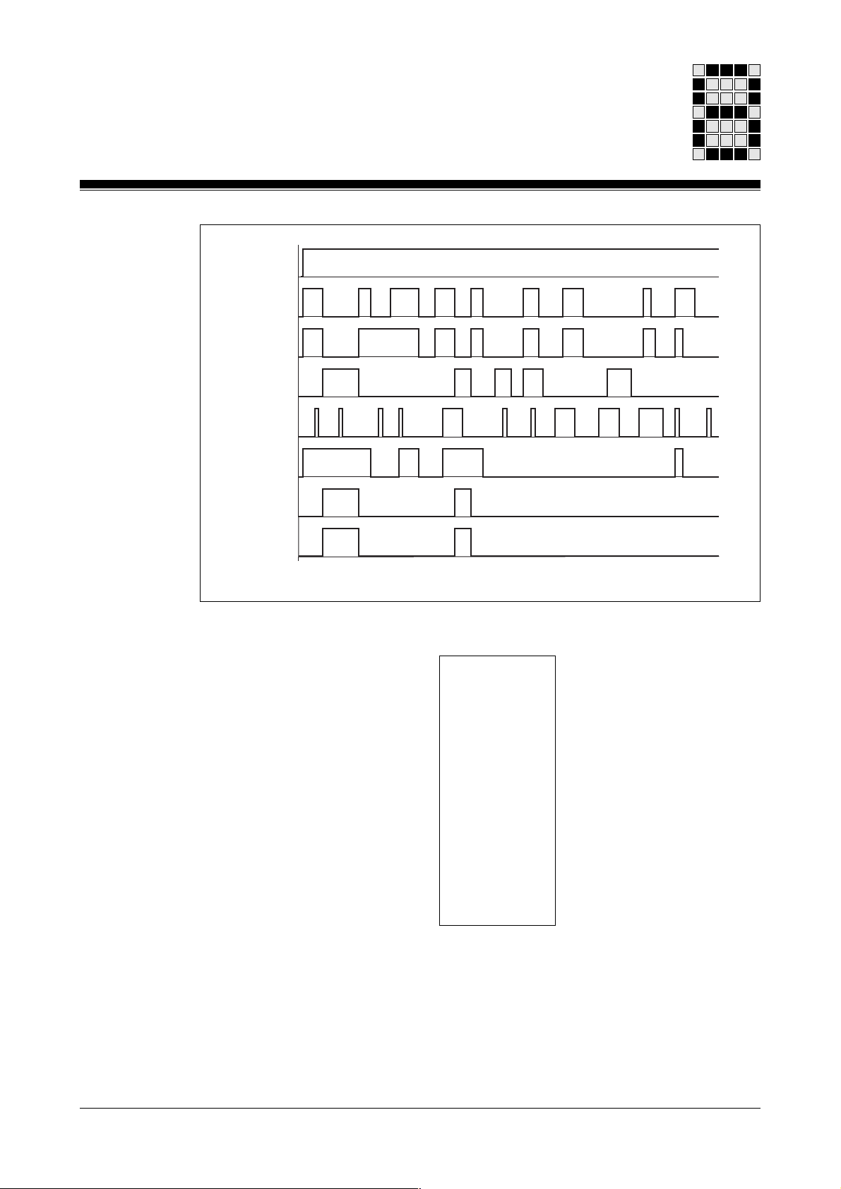
PSSSTART
E0.01
E0.02
E0.08
E0.31
M72.01
A1.00
A1.08
1
0
1
0
1
0
1
0
1
0
1
0
1
0
1
0
Fig. 8-10: Timing diagram
Program:
KF 000500
M 110.01 .RLO-1 E 0.08 .M1_ON E 0.01 .FbL-K-M1.1 E 0.02 .FbL-K-M1.2 KF 000300 .Mon.Time E 0.31 .Reset
SB065
FBL
W - SSNR
X - GRP
X - ON
X - FbL1
X - FbL2
W - TFbL
X - RSET
ENBL - X
K1 - X
K2 - X
- M 072.01 .FG-M1
- A 1.00 .K-M1.1
- A 1.08 .K-M1.2
8-11Modular Block System: Emergency Stop Circuits
Page 96
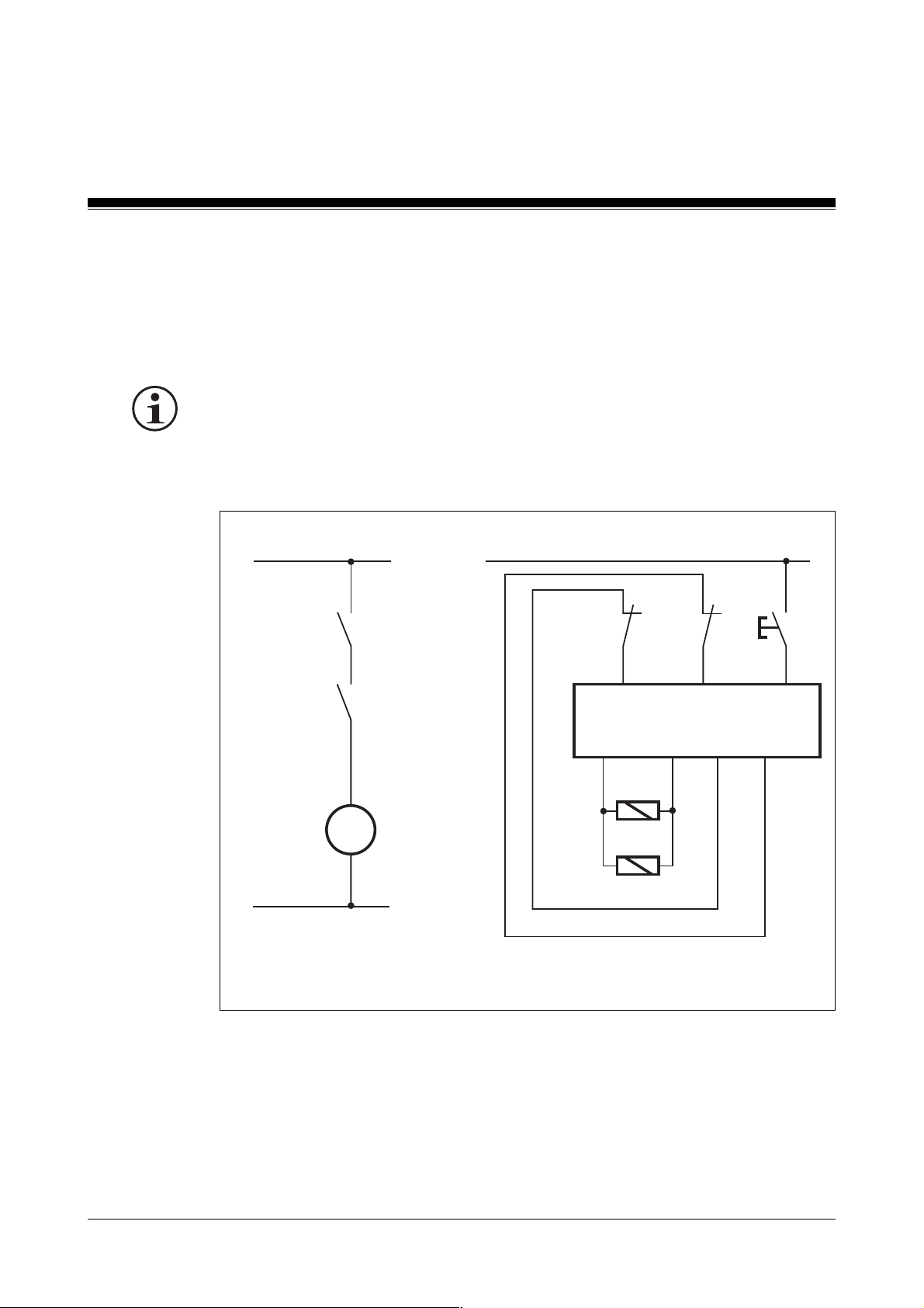
Examples
Feedback loop monitoring (shutdown with two main contactors connected in series and pulsed outputs), category 4
Block: SB067/RFK_K4
INFORMATION
If wired outside the control cabinet, or if there is any possibility of a short
circuit, the feedback loops must be allocated pulsed outputs (A0.16 and
A0.17); this must be entered in the configurator (DB002).
L1 24 V
K-M1.1
K-M1.2
M1
N
Fig 8-11: Wiring diagram
M
RFK
K-M1.1
K-M1.1
K-M1.2
RFK
K-M1.2
E0.01 E0.02 E0.08
PSS
+ A1.16 -
M1
START
pulsed outputs
A0.16 A0.17
8-12
Modular Block System: Emergency Stop Circuits
Page 97
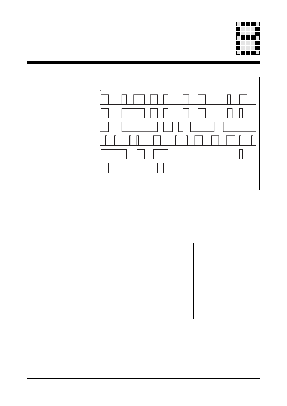
PSS
PSS-
START
START
E00.01
E00.02
E00.08
E00.31
M72.01
M72.01
A01.16
E0.01
E0.02
E0.08
E0.31
A1.16
1
0
1
1
0
1
1
0
1
1
0
1
1
0
1
1
0
1
1
0
Fig. 8-12: Timing diagram
Program:
KB 006
E 0.01 .RFK-K-M1.1 E 0.02 .RFK-K-M1.2 E 0.31 .Reset E 0.08 .M1_START -
SB 067
RFK_K4
B - SSNR
X - RFK1
X - RFK2
X - RSet
X - Ein
FG - X
K- X
- M 072.01 .FG-M1
- A 1.16 .K-M1.1/2
8-13Modular Block System: Emergency Stop Circuits
Page 98
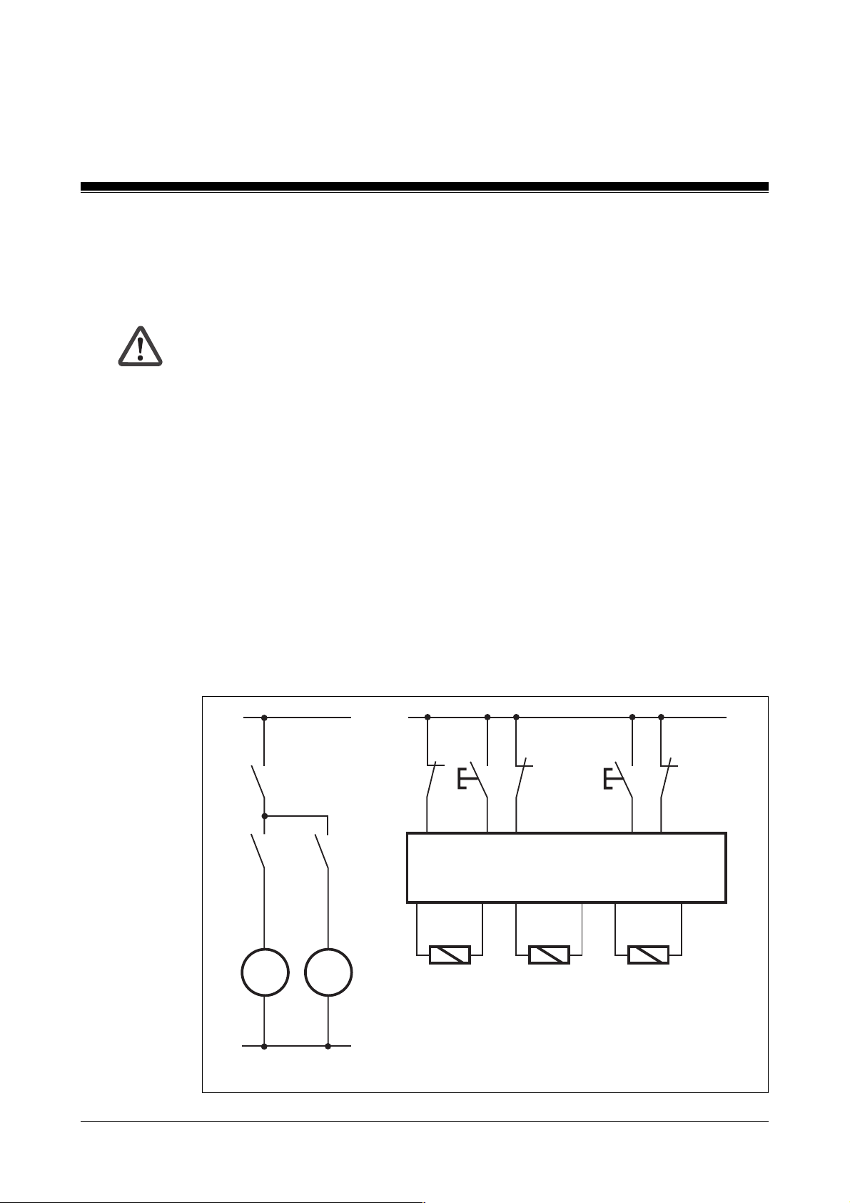
Examples
Feedback loop monitoring (selective shutdown), category 4
Block used: SB067/RFK_K4
WARNING!
If only one contactor is used to switch a potentially dangerous drive, it
must be possible to switch this contactor off via a group contactor situated
within the current path. This group contactor must be controlled with the
AND-linked FG-signals of the individual main contactors and must be
monitored with a feedback loop.
The subordinate main contactors may only switch on if the group contactor
monitor FG = 1. The switch-on signal from the subordinate contactors
must form an AND-connection with the FG-signal from the group contactor
and must be assigned to the
Ein
-parameter of the main contactor monitor.
If only one feedback loop is used, the feedback input will be connected to
RFK1
and
RFK2
.
Please note:
The feedback loops must be wired inside the control cabinet. If this is not
possible, the feedback loops must be pulsed.
K-M1.2
M1.2
24 V
RFK
K-G1
E0.0
+ A1.16 -
K-G1
M1.1
START
E0.8
PSS
M1.2
START
E0.9
E0.2
RFK
K-M1.1
E0.1
+ A1.17 - + A1.18 -
K-M1.1 K-M1.2
RFK
K-M1.2
L1
K-G1
K-M1.1
M1.1
M M
8-14
N
Fig 8-13: Wiring diagram
0 V
Modular Block System: Emergency Stop Circuits
Page 99

Program:
Motor 1.1 :Segment 01
: L A 1.16 .K-G1 K-M1.1 switches on if K-G1 is “1” and
: U E 0.08 .M1.1_Start start command (here E 0.08) is “1”.
: = M 070.01 .K-M1.1_Start
: CAL SB 067
SB 067
RFK_K4
KB 008
E 0.01 .RFK-K-M1.1 E 0.01 .RFK-K-M1.1 E 0.31 .Reset M 070.01 .K-M1.1_Start -
B - SSNR
X - RFK1
X - RFK2
X - RSet
X - Ein
FG - X
K- X
- M 072.01 .FG-M1.1
- A 1.17 .K-M1.1
Motor 1.2 :Segment 02
: L A 1.16 .K-G1 K-M1.2 switches on if K-G1 is “1” and
: U E 0.09 .M1.2_Start the start command (here E 0.09) is “1”.
: = M 070.02 .K-M1.2_Start
: CAL SB 067
SB 067
RFK_K4
KB 009
E 0.02 .RFK-K-M1.2 E 0.02 .RFK-K-M1.2 E 0.31 .Reset M 070.02 .K-M1.2_Start -
B - SSNR
X - RFK1
X - RFK2
X - RSet
X - Ein
FG - X
K- X
- M 072.02 .FG-M1.2
- A 1.18 .K-M1.2
Group 1 :Segment 03
: L M 072.01 .FG-M1.1 K-G1 can only switch on if K-M1.1 and
: U M 072.02 .FG-M1.2 K-M1.2 are error-free.
: = M 070.00 .K-M1.2_Start
8-15Modular Block System: Emergency Stop Circuits
Page 100

Examples
: CAL SB 067
KB 010
E 0.00 .RFK-K-G1 E 0.00 .RFK-K-G1 E 0.31 .Reset M 070.00 .FG -
SB 067
RFK_K4
B - SSNR
X - RFK1
X - RFK2
X - RSet
X - Ein
FG - X
K- X
- M 072.00 .FG-G1
- A 1.16 .K-G1
8-16
Modular Block System: Emergency Stop Circuits
 Loading...