

Page 1

PSSnet GW1 MOD-CAN
Gateways
Operating Manual-1002693-EN-02
Page 2

Preface
This document is a translation of the original document.
All rights to this documentation are reserved by Pilz GmbH & Co. KG. Copies may be made
for internal purposes. Suggestions and comments for improving this documentation will be
gratefully received.
Pilz®, PIT®, PMI®, PNOZ®, Primo®, PSEN®, PSS®, PVIS®, SafetyBUS p®, SafetyEYE®,
SafetyNET p®, the spirit of safety® are registered and protected trademarks of Pilz GmbH
& Co. KG in some countries.
SD means Secure Digital
Page 3

Content
Section 1 Introduction 5
1.1 Validity of documentation 5
1.2 Retaining the documentation 5
1.3 Definition of symbols 5
Section 2 Overview 6
2.1 Module features 6
2.2 Unit view 7
2.2.1 Front 7
2.2.2 Top 8
2.2.3 Right-hand side 8
2.2.4 Bottom 9
Section 3 Safety 10
3.1 Intended use 10
3.1.1 Electromagnetic compatibility 10
3.1.1.1 Connecting the earth cables 11
3.1.1.2 Cable routing 12
3.1.1.3 Equipotential bonding 12
3.1.1.4 Shielding 13
3.1.1.5 Lighting in the control cabinet 13
3.1.1.6 Testing the EMC-compliance of an installation 13
3.2 Safety regulations 14
3.2.1 Use of qualified personnel 14
3.2.2 Warranty and liability 15
3.2.3 Disposal 15
3.3 Safety during installation 15
Section 4 Function description 16
4.1 Operation 16
4.1.1 Block diagram 17
4.2 Modbus/TCP 17
4.2.1 Modbus/TCP data ranges (Server connections) 17
4.2.2 Data transfer limits 18
4.2.3 Function codes (Client connections) 18
4.3 CANopen 20
4.4 Translation tables 20
4.4.1 Payload 20
4.4.2 Diagnostic data 21
4.5 Interfaces 24
Section 5 Installation 25
5.1 General installation guidelines 25
5.1.1 Dimensions 26
5.2 Mounting distances 27
5.3 Supply voltage 27
5.4 Install Gateway 28
Operating Manual PSSnet GW1 MOD-CAN
1002693-EN-02
3
Page 4

Content
Section 6 Commissioning 29
6.1 General wiring guidelines 29
6.2 Wiring the units 29
6.2.1 Cable requirements 29
6.2.2 Terminals 30
6.3 Terminal configuration 30
6.4 Interfaces 30
6.4.1 CANopen interface 30
6.4.2 CANopen termination 31
6.4.3 RJ45 interface 31
6.4.3.1 RJ45 connection cable 31
6.5 Set addresses and transmission rate 32
6.5.1 Set IP address 32
6.5.2 Set device address 33
6.5.3 Setting the transmission rate 34
Section 7 Operation 35
7.1 Display elements 35
7.1.1 Display elements for device diagnostics 35
7.2 Web server 36
7.2.1 Call web server 36
7.2.2 Password management 36
7.3 Exchange Gateway 37
Section 8 Technical details 38
Section 9 Order reference 41
Operating Manual PSSnet GW1 MOD-CAN
1002693-EN-02
4
Page 5
Introduction
1
1.1
1.2
1.3
Introduction
Validity of documentation
This documentation is valid for the product PSSnet GW1 MOD-CAN. It is valid until new
documentation is published.
This operating manual explains the function and operation, describes the installation and
provides guidelines on how to connect the product.
Retaining the documentation
This documentation is intended for instruction and should be retained for future reference.
Definition of symbols
Information that is particularly important is identified as follows:
DANGER!
This warning must be heeded! It warns of a hazardous situation that poses
an immediate threat of serious injury and death and indicates preventive
measures that can be taken.
WARNING!
This warning must be heeded! It warns of a hazardous situation that could
lead to serious injury and death and indicates preventive measures that can
be taken.
ATTENTION!
This refers to a hazard that can lead to a less serious or minor injury plus
material damage, and also provides information on preventive measures
that can be taken.
CAUTION!
This describes a situation in which the product or devices could be damaged and also provides information on preventive measures that can be taken. It also highlights areas within the text that are of particular importance.
Information
This gives advice on applications and provides information on special features.
Operating Manual PSSnet GW1 MOD-CAN
1002693-EN-02
5
Page 6

Overview
2
2.1
Overview
Module features
The PSSnet GW1 MOD-CAN
} operates as a protocol converter between Modbus/TCP and CANopen,
} can be used to exchange data between products that support Modbus/TCP or CAN-
open . For example, this may be a control system from the automation system
PSS 4000 from Pilz on one side and a third-party product on the other. The third party
product must support CANopen .
Features of the PSSnet GW1 MOD-CAN:
} Can be used with Pilz products that support Modbus/TCP:
– Control systems from the automation system PSS 4000 (e.g. PSSu H)
– Compact/modular 3rd generation PSS-range programmable safety systems (e.g.
PSS SB 3006-3 ETH-2, PSS(1) SB CPU3 ETH-2)
– Operator terminals PMI with Modbus/TCP interface (e.g. PMI 5)
– Motion control systems (e.g. PMCprimo Drive3, PMCprimo DriveP, PMCprimo 16+)
} 1 x RJ45 socket for connection to Modbus/TCP,
} Can manage up to 8 Modbus/TCP connections
} Can operate as a Modbus/TCP connection Server,
} Web server for managing and configuring the Gateway,
} Supports CiA 301 V4.2.0,
} Operates as a Slave in the CANopen network,
} Transmission rate 10 MBit/s (10BaseT) and 100 MBit/s (100BaseTX),
} 1 x male 9-pin D-Sub connector for connection to CANopen,
} supports autonegotiating,
} LEDs for displaying the communication status and errors,
} input/output data
– up to 512 Bytes acyclical data (SDO),
– in total (RxPDO and TxPDO) max. 512 Bytes,
– additionally it is possible to transfer data between the control systems,
} supply voltage
– 20 ms buffer in case of supply interruptions,
– plug-in connection terminals (either spring-loaded terminal or screw terminal).
Operating Manual PSSnet GW1 MOD-CAN
1002693-EN-02
6
Page 7
Overview
2.2
2.2.1
Unit view
Front
22,5 (0,88“)
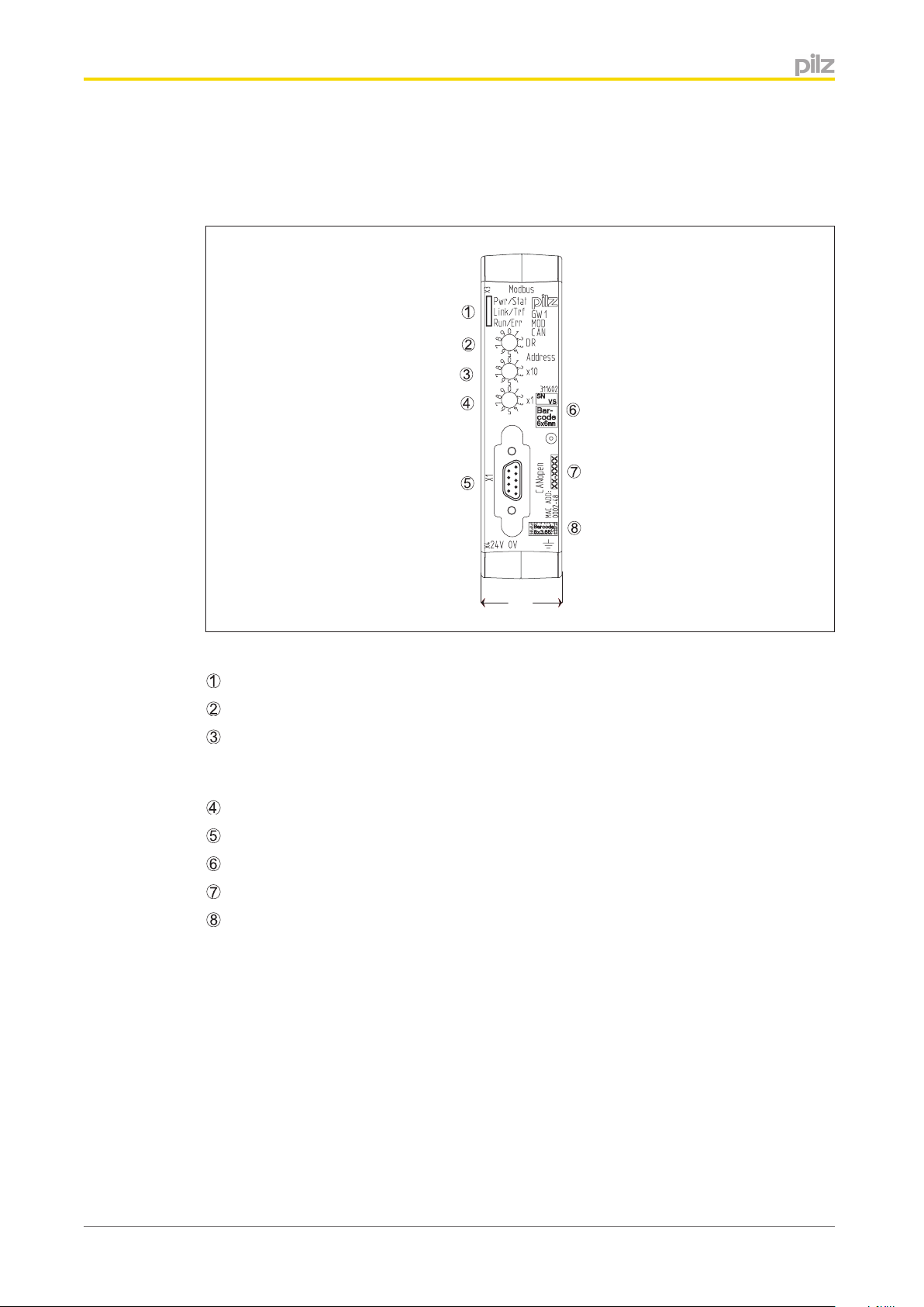
Front view
: LEDs for displaying the communication status and faults
: Rotary switch DR for setting the transmission rate
: Rotary switch X10 for setting the tens digit of the device address; this is the address
used to address the Gateway of the CANopen Master. This address must be set in the software for the CANopen Master
: Rotary switch X1 for setting the units digit of the device address for this Gateway
: CANopen interface (male 9-pin D-Sub connector)
: Barcode with the item number, serial number and version of the Gateway
: MAC address
: 2D code with the MAC address
Operating Manual PSSnet GW1 MOD-CAN
1002693-EN-02
7
Page 8
Overview
2.2.2
Top
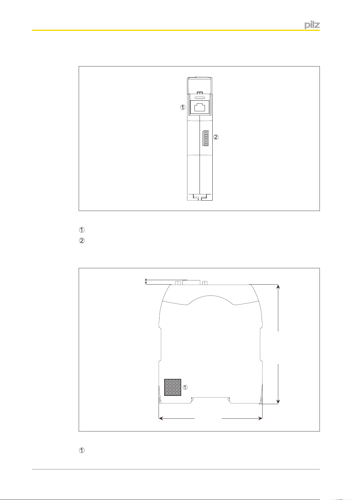
Top
: Modbus/TCP interface (RJ45)
OFFON
128
64
32
16
IP-ADDRESS
8
4
2
1
2.2.3
: DIP switch for IP address
Right-hand side
4,25 (0,17“)
1
2
4
8
16
32
64
128
110 (4,33“)
IP-Address
Right-hand side
: QR code with a link to the Pilz homepage with further information on the Gateway
Operating Manual PSSnet GW1 MOD-CAN
1002693-EN-02
96 (3,78“)
8
Page 9
Overview
2.2.4
Bottom
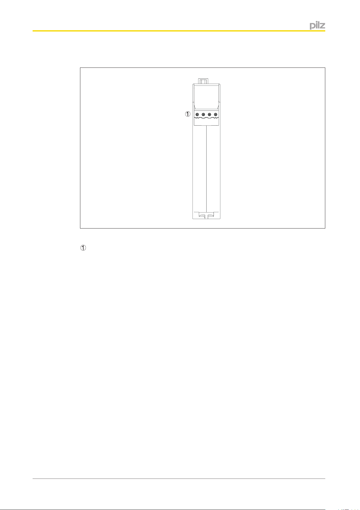
Bottom
: Supply voltage connection
Operating Manual PSSnet GW1 MOD-CAN
1002693-EN-02
9
Page 10

Safety
3
3.1
Safety
Intended use
The product serves as a protocol converter between Modbus/TCP and CANopen. It can be
used with various Pilz products as well as third-party products, provided they support the
documented properties and requirements.
} Modbus/TCP
The Gateway can be used with products that operate as connection Client during data
exchange. The product must support at least one of the documented function codes .
} CANopen
The Gateway can be used as a passive subscriber (Slave) in a CANopen network. The
basic functions of communication via CANopen correspond to the System Description
published by the CANopen User Group.
The Gateway may not be used for safety-related functions.
Intended use includes making the electrical installation EMC-compliant. The product is designed for use in an industrial environment. It is not suitable for use in a domestic environment, as this can lead to interference.
The following is deemed improper use in particular:
} Any component, technical or electrical modification to the product
} Use of the product outside the areas described in this manual
} Use of the product outside the technical details (see chapter entitled “Technical De-
tails”)
3.1.1
Electromagnetic compatibility
To ensure electromagnetic compatibility the correct procedures must be carried out during
installation.
A device is electromagnetically compatible if:
} It functions without error in a given electromagnetic environment
} It does not adversely affect its own environment.
Electromagnetic interference can reach the devices through:
} Fields
} Power supplies
} Earth cabling
} Bus connections
} Interfaces
} Input and output cables
The interference can be transferred from the producer (source) to the receiver (interference
sink) via the coupling routes.
Interference reaches the interference sink (e.g. the control system devices) in various ways:
} DC coupling:
DC coupling occurs if the source and sink of interference have common cable connec-
tions. The common cable presents complex resistances, inducing potential differences.
Operating Manual PSSnet GW1 MOD-CAN
1002693-EN-02
10
Page 11
Safety
Typical sources of interference are switches/relays, running motors or varying potentials
for other systems on the same power supply.
} Capacitive (electrical) coupling:
A different potential between the source and interference sink (e.g. two cables) creates
an electrical field. Coupling is proportional to the rate of voltage change.
Typical sources of interference are contactors, static discharge, parallel signal cables.
} Inductive (magnetic) coupling:
A live cable produces a magnetic field which also surrounds adjacent cables. Interfer-
ence voltage is induced. Coupling is proportional to the rate of current change.
Typical sources of interference are mains cables running in parallel, live cables, high
frequency cables, inductors, transformers, motors.
} Electromagnetic coupling:
A cable can emit a signal as a radio wave. This wave is then picked up by another ca-
ble.
Typical sources of interference are transmitters such as radios, sparks from spark
plugs, welding equipment, etc.
3.1.1.1
CAUTION!
Powerful HF transmitters should only be operated at a distance of more
than 0.6 m.
} Static discharge:
Static discharge occurs where there are very high differences in potential between two
points. If the two points are brought closer together or if the potential difference is increased, discharges can occur in the air gaps.
Typical sources of interference are people who are statically charged from a synthetic
carpet, for example.
Connecting the earth cables
Please note:
} A conductor cross section of at least 2.5 mm
2
should be used for the connection to the
central earth bar. Connections should be kept as short as possible.
} Connections to the earth bar should always be in star form.
} Connect together the 0V connections on all the 24 V power supplies and earth the 0 V
mains at a single point, or ensure that measures are in place to monitor for earth faults.
Earthed supply voltages offer the best noise immunity.
} The connection of the 0 V supply to the central earth bar or earth fault monitor must be
in accordance with relevant national regulations (such as EN 60204-1, NFPA 79:17-7,
NEC: Article 250).
} Connections should be protected from corrosion.
} Flexible earthing straps should be used on moving earth parts (e.g. machine parts,
gates). Ensure these earthing straps are as short and wide as possible.
Operating Manual PSSnet GW1 MOD-CAN
1002693-EN-02
11
Page 12

Safety
3.1.1.2
Cable routing
It is possible to differentiate between cables according to their function. The
following groups exist:
}
Group 1: Data and supply lines for DC voltages below 60 V and AC voltages below 25 V
} Group 2: Data and supply lines for DC voltages from 60 V to 400 V and AC voltages
from 25 V to 400 V.
} Group 3: Supply lines above 400 V
Cabling inside buildings:
} The cable groups listed above should be laid separately.
} Cables of the same group can be laid within the same cable duct.
} Cables from group 1 and group 2 should be laid in separate groups or in cable ducts
which are at least 10 cm apart.
} Cables from group 1 and group 3 should be laid in separate groups or in cable ducts
which are at least 50 cm apart.
} Data and signal lines should be laid as close as possible to an earthed surface.
Cabling to open air systems:
} As far as possible use metal conduits. These should be electrically connected and
earthed.
} Ensure there is sufficient protection against lightning by using metal conduits earthed at
both ends, or concrete cable ducts with reinforcements connected across the joints.
3.1.1.3
Equipotential bonding
Potential differences can occur if the devices are connected to different earth or ground
connections. Even cable shields that are connected at either end and have different earth
connections can cause potential differences. In order to avoid interference, equipotential
bonding cables must be installed.
In doing so you must ensure the following:
} Select a low impedance equipotential bonding cable.
} Select the following as standard values for the cross section of the equipotential bond-
ing cables:
– 16 mm
– 25 mm
2
for equipotential bonding cable up to 200 m in length
2
for equipotential bonding cable over 200 m in length
} If the control system devices are connected with shielded signal cables which are
earthed at either end, the impedance is calculated as follows:
– Impedance equipotential bonding cable = 10 % of shield impedance
} Use copper or galvanised steel equipotential bonding cable.
} Connect equipotential bonding cables to the earth bar over as wide a surface area as
possible.
} As short a distance as possible should be kept between the equipotential bonding cable
and signal cable.
Operating Manual PSSnet GW1 MOD-CAN
1002693-EN-02
12
Page 13

Safety
3.1.1.4
Shielding
Interference currents must be diverted to cable shields via shield bars.
In doing so you must ensure the following:
} Connect the shields with low impedance to the shield bar or earth bar.
} Use cables with braided screening, with a minimum cover area of 80 %.
} When laying cables without equipotential bonding or using foil shields: Connect the
shield at one end.
} If possible, use metal or metallised plugs to connect cables for serial data transfer. Al-
ways refer to the regulations relating to the fieldbus systems.
} If the shield is not to be connected at the end of the cable, it must have no connection
to the connector housing.
} If the shield is to be connected, connect it to the shield bar at the point where the cable
enters the cabinet, without making a break in the cable. Use metal cable clamps which
cover the shield over a wide surface area. Route the shield as far as the units, but do
not connect it to the units.
Digital inputs and outputs do not need shielded cables.
However, if the connection cables have a shield, it should be connected at one end.
Analogue inputs and the incremental encoder inputs on speed monitors should always be
connected using shielded cables.
3.1.1.5
3.1.1.6
Lighting in the control cabinet
Use low interference panel lighting for inside the control cabinet.
Testing the EMC-compliance of an installation
You can use the list below to check that the installation of the Gateway is EMC-compliant.
Check Measures Done
Are there areas with a high
probability of interference?
EMC protection in these areas should be planned
with particular care.
(e.g. computers running,
process control areas, distribution cabinets, cable
casing, frequency converters, hand-held radios etc.).
Are areas where comput-
If necessary shield the whole area.
ers are running or areas
such as process control
rooms sufficiently shielded
from electromagnetic coupling?
Does the cable layout take
into account the principles
of EMC compliance?
Some important points: Lay cables close to earth,
keep clear of other electrical equipment, keep ca-
bles in ducts separate from other parts of the in-
stallation, keep cables as short as possible, avoid
multiple crossovers.
Is the supply voltage free
of interference?
Operating Manual PSSnet GW1 MOD-CAN
1002693-EN-02
Supplies with interference voltages should be fit-
ted with a mains filter.
13
Page 14

Safety
Check Measures Done
EMC characteristics of individual units / all units
tested once installed?
Earthed parts connected
correctly?
Cable groups laid separately?
Are the shields connected
correctly?
Equipotential bonding carried out?
Test EMC characteristics under operating condi-
tions, e.g. while hand-held radios are in use, or
HF frequency generators are close by. Test static
discharge with operating personnel, test mutual
interference between units under different operat-
ing conditions.
The connections between the units, racking bars,
earth conductors and shield bars are important.
Inactive metal parts should be connected over a
wide surface area and earthed at a central point;
with insulated metal: Remove insulation or use
special contact fixings; protect the connection
from corrosion; connect the cabinet doors to the
body of the cabinet using earthing straps.
Separate cables into groups. Supply and signal
leads should be laid separately.
Use shielded cables for analogue and data leads;
use metallic plugs; connect cable shields to shield
bar at point of entry to cabinet; connect cable
shields over a wide surface area and with low im-
pedance.
If the installation extends over a wide area: lay
equipotential bonding cable.
3.2
3.2.1
Are inductive loads
switched?
24 VDC power supply? Power supplies must conform to EN
Sufficient fuse protection should be used with in-
ductive loads
60742:9/1995, EN 60950-1:2006/A11:2009 or EN
50178: 10/97.
Safety regulations
Use of qualified personnel
The products may only be assembled, installed, programmed, commissioned, operated,
maintained and decommissioned by competent persons.
A competent person is someone who, because of their training, experience and current professional activity, has the specialist knowledge required to test, assess and operate the
work equipment, devices, systems, plant and machinery in accordance with the general
standards and guidelines for safety technology.
It is the company’s responsibility only to employ personnel who:
} Are familiar with the basic regulations concerning health and safety / accident preven-
tion
} Have read and understood the information provided in this description under "Safety"
} And have a good knowledge of the generic and specialist standards applicable to the
specific application.
Operating Manual PSSnet GW1 MOD-CAN
1002693-EN-02
14
Page 15

Safety
3.2.2
3.2.3
3.3
Warranty and liability
All claims to warranty and liability will be rendered invalid if
} The product was used contrary to the purpose for which it is intended
} Damage can be attributed to not having followed the guidelines in the manual
} Operating personnel are not suitably qualified
} Any type of modification has been made (e.g. exchanging components on the PCB
boards, soldering work etc.).
Disposal
When decommissioning, please comply with local regulations regarding the disposal of
electronic devices (e.g. Electrical and Electronic Equipment Act).
Safety during installation
The product requires a 24 VDC supply. Check that the external power supply provides this
voltage.
The tolerance of the supply voltage must comply with the technical details. Safe operation
cannot be guaranteed outside this range.
Protect the external power supply by fitting a fuse between the external power supply and
the product. The size of the fuse will depend on the specification of the external power supply, the conductor cross section and on local regulations.
WARNING!
Risk of electrocution!
Safe electrical isolation must be ensured for the external power supply that
generates the supply voltage. Failure to do so could result in electric shock.
The power supplies must comply with EN 60950-1:2006/A11:2009, EN
61558-2-6:11/1997.
WARNING!
Risk of electrocution!
When voltage is applied, contact with live components could result in serious or even fatal injury from an electric shock.
Operating Manual PSSnet GW1 MOD-CAN
1002693-EN-02
15
Page 16

Function description
4
4.1
Function description
Operation
The Gateway
} operates as a protocol converter between Modbus/TCP and CANopen,
} operates on the Modbus/TCP side as connection Server and on the CANopen-side as
Slave,
} Uses an LED to indicate whether there is data traffic via the connection
} Uses an LED to indicate the interface used for this data traffic
} If the connection to CANopen or to Modbus/TCP is no longer available, the payload is
retained with the current values
} is exclusively designed for exchanging non-safety-related data
The Gateway is interposed in the data flow between the connected devices.
Protocol conversion, Modbus/TCP to CANopen
} Signal path from CANopen-enabled product to Modbus/TCP-enabled product:
CANopen-enabled product
version
uct
} Signal path from Modbus/TCP-enabled product to CANopen-enabled product:
Modbus/TCP-enabled product
tocol conversion
product
-> Data input/output Modbus/TCP interface -> Modbus/TCP-enabled prod-
-> CANopen interface on the Gateway -> CANopen-enabled
-> CANopen interface on the Gateway -> Protocol con-
-> Data input/output Modbus/TCP interface -> Pro-
Operating Manual PSSnet GW1 MOD-CAN
1002693-EN-02
16
Page 17

Function description
4.1.1
4.2
Block diagram
1x CANopen
Connection to
Modbus/TCP
Mapping
Block diagram
24 V
0 V
Power
Modbus/TCP
The Gateway can manage a max. of 8 Modbus/TCP connections. The Gateway is always
the connection Server. The connection Clients may be various devices, e.g. PC, control
system, display unit. They can access the Gateway simultaneously.
4.2.1
Port number "502" in the Gateway is set as the default for data exchange via a Modbus/
TCP connection.
Modbus/TCP data ranges (Server connections)
The product supports the following Modbus/TCP data areas:
Data area Modbus syntax Example
Coils (Bit)
0x00000 … 0x65535
[read/write]
Discrete Inputs (Bit)
1x00000 … 1x65535
[read only]
Input Register (Wort/16 Bits)
3x00000 … 3x65535
[read only]
Holding Register (Wort/16
Bits)
4x00000 … 4x65535
[read/write]
Modbus/TCP data areas
0x[xxxxx] 0x00031
1x[xxxxx] 1x08193
3x[xxxxx] 3x00002
4x[xxxxx] 4x00805
Operating Manual PSSnet GW1 MOD-CAN
1002693-EN-02
17
Page 18

Function description
Information
Addressing for Pilz systems starts at "0". On devices from other manufacturers, addressing may start at "1".
Please refer to the operating manual provided by the relevant manufacturer.
4.2.2
Data transfer limits
This table contains the maximum data lengths supported per telegram:
Data transfer Max. data length per tele-
gram
Read data (Bit) FC 01 (Read Coils) 1 … 2000
FC 02 (Read Discrete Inputs)
Read data (Word) FC 03 (Read Holding Regis-
ters)
FC 04 (Read Input Register)
Write data (Bit) FC 05 (Write Single Coil) 1 Bit
FC 15 (Write Multiple Coils) 1 … 1968
Write data (Word) FC 06 (Write Single Regis-
ter)
FC 16 (Write Multiple Registers)
Read and write data (Word) FC 23 (Read/Write Multiple
Registers)
1 … 125
1 Word
1 … 123 Words
Read 1 … 125 Words
Write 1 … 121 Words
4.2.3
Data transfer limits
Information
There may be some restrictions in data length, depending on the device that
is used. Please refer to the information stated in the operating manual of the
relevant unit.
Function codes (Client connections)
The connection Client can access the Gateway's data areas using the following function
codes (FC):
Data area Modbus syntax Example
FC 01 Read Coils The connection Client reads
bit data from the connection
Server,
data length = 1 Bit, content,
content: input/output data
(data received from 0x)
Operating Manual PSSnet GW1 MOD-CAN
1002693-EN-02
18
Page 19

Function description
Data area Modbus syntax Example
FC 02 Read Discrete Input The connection Client reads
FC 03 Read Holding Register The connection Client reads
FC 04 Read Input Register The connection Client reads
bit data from the connection
Server,
data length = 1 Bit, content,
content: input/output data
(data received from 1x)
word data from the connection Server,
data length = 1 Word,
content: diagnostic word
(data received from 4x)
word data from the connection Server,
data length = 1 Word,
content: diagnostic word
(data received from 3x)
FC 05 Write Single Coil The connection Client writes
to one bit datum in the connection Server,
data length = 1 Bit,
content: input data (send
data to 0x)
FC 06 Write Single Register The connection Client writes
to one word datum in the
connection Server,
data length = 1 Word,
content: input data (send
data to 4x)
FC 15 Write Multiple Coils The connection Client writes
to multiple bit data in the
connection Server,
data length = 1 Bit,
content: input data (send
data to 0x)
FC 16 Write Multiple Registers The connection Client writes
to multiple word data in the
connection Server,
data length = 1 Word,
content: input data (send
data to 4x)
FC 23 Read/Write Multiple Regis-
Operating Manual PSSnet GW1 MOD-CAN
1002693-EN-02
ters
The connection Client reads
and writes multiple word data
within a telegram
(receive data from 3x and
send data to 4x)
19
Page 20

Function description
4.3
4.4
4.4.1
CANopen
The manufacturer's ID, the device ID and any functions supported by a field device are defined in a device description file. The device description file (Electronic Data Sheet, EDS) is
fieldbus-dependent. The content and format of a device description file are specified in the
fieldbus standard. The file is needed in order to include an unknown field device in the respective fieldbus configuration tool and in order to configure the plant-specific requirements.
An EDS file in a standardised text format is used for CANopen devices.
Translation tables
Only Register 4x is represented in the tables. The same assignment applies for Registers
0x, 1x, and 3x.
Payload
Modbus CANopen
SDO
Subindex
Register Byte PDO COB-ID Index
4x00001 Low Byte RxPDO1 0x200 + Node-Id 2000 1
(hex)
High Byte 2
4x00002 …
400004
4x00005 Low Byte RxPDO2 0x300 + Node-Id 2000 9
4x00006 …
4x00008
4x00009 Low Byte RxPDO3 0x400 + Node-Id 2000 11
4x00010 …
4x00012
4x00013 Low Byte RxPDO4 0x500 + Node-Id 2000 19
4x00014 …
4x00016
4x00129 Low Byte TxPDO1 0x180 + Node-Id 2002 1
4x00130 …
4x00132
Low Byte
High Byte
High Byte A
Low Byte
High Byte
High Byte 12
Low Byte
High Byte
High Byte 1A
Low Byte
High Byte
High Byte 2
Low Byte
High Byte
3 … 8
B … 10
13 … 18
1B … 20
3 … 8
4x00133 Low Byte TxPDO2 0x280 + Node-Id 2002 9
High Byte A
4x00134 …
4x00136
Operating Manual PSSnet GW1 MOD-CAN
1002693-EN-02
Low Byte
High Byte
B … 10
20
Page 21

Function description
4x00137 Low Byte TxPDO3 0x380 + Node-Id 2002 11
Modbus CANopen
Register Byte PDO COB-ID Index
High Byte 12
SDO
Subindex
(hex)
4.4.2
4x00138 …
4x00140
4x00141 Low Byte TxPDO4 0x480 + Node-Id 2002 19
4x00142 …
4x00144
Key to abbreviations:
TxPDO: Transmit Process Data Object
RxPDO: Receive Process Data Object
Low Byte
High Byte
High Byte 1A
Low Byte
High Byte
13 … 18
1B … 20
Diagnostic data
CANopen SDO Modbus Register Access type Meaning in CANopen
Subin-
dex
Index
200a 001 4x01001 Low Byte RO IP address (Modbus),
200a 002 High Byte RO IP address (Modbus),
(hex)
LL Byte
LH Byte
200a 003 4x01002 Low Byte RO IP address (Modbus),
HL Byte
200a 004 High Byte RO IP address (Modbus),
HH Byte
200a 005 4x01003 Low Byte RO Subnet Mask (Mod-
bus), LL Byte
200a 006 High Byte RO Subnet Mask (Mod-
bus), LH Byte
200a 007 4x01004 Low Byte RO Subnet Mask (Mod-
bus), HL Byte
200a 008 High Byte RO Subnet Mask (Mod-
bus), HH Byte
200a 009 4x01005 Low Byte RO Gateway (Modbus),
LL Byte
200a 00A High Byte RO Gateway (Modbus),
LH Byte
200a 00B 4x01006 Low Byte RO Gateway (Modbus),
HL Byte
Operating Manual PSSnet GW1 MOD-CAN
1002693-EN-02
21
Page 22

Function description
CANopen SDO Modbus Register Access type Meaning in CANopen
200a 00C High Byte RO Gateway (Modbus),
200a 00D 4x01007 Low Byte RO DHCP activated (Mod-
200a 00E High Byte RO Reserved
200a 00F 4x01008 Low Byte RO Max. number of Mod-
200a 010 High Byte RO Reserved
200a 011 4x01009 Low Byte RO Current number of
200a 012 High Byte RO Reserved
200a 013 4x01010 Low Byte RO Modbus Port Number,
Index
Subin-
dex
(hex)
HH Byte
bus)
bus connections
Modbus connections
L Byte, (default: 502)
200a 014 High Byte RO Modbus Port Number,
H Byte, (default: 502)
200a 015 4x01011 Low Byte RO Keep Alive Time of
Modbus connections
in ms, L Byte, (default:
32000)
200a 016 High Byte RO Keep Alive Time of
Modbus connections
in ms, H Byte, (default: 32000)
200a 017 4x01012 Low Byte RO Reserved
200a 018 High Byte RO Reserved
200a 019 4x01013 Low Byte RO Reserved
200a 01A High Byte RO Reserved
200a 01B 4x01014 Low Byte RO Reserved
200a 01C High Byte RO Reserved
200a 01D 4x01015 Low Byte RO Reserved
200a 01E High Byte RO Reserved
200a 01F 4x01016 Low Byte RO Reserved
200a 020 High Byte RO Reserved
200a 021 4x01017 Low Byte RO Reserved
200a 022 High Byte RO Reserved
200a 023 4x01018 Low Byte RO Reserved
200a 024 High Byte RO Reserved
200a 025 4x01019 Low Byte RO Reserved
200a 026 High Byte RO Reserved
200a 027 4x01020 Low Byte RO CANopen address
Operating Manual PSSnet GW1 MOD-CAN
1002693-EN-02
22
Page 23

Function description
CANopen SDO Modbus Register Access type Meaning in CANopen
200a 028 High Byte RO Reserved
200a 029 4x01021 Low Byte RO CANopen bit rate, for
200a 02A High Byte RO Reserved
200a 02B 4x01022 Low Byte RO
200a 02C High Byte RO Reserved
200a 02D 4x01023 Low Byte RO
200a 02E High Byte RO Reserved
Index
Subin-
dex
(hex)
the bit rates for the
values Setting the
transmission rate [
34]
CANopen RUN status
} 0 = LED off
} 1 = LED on
} 5 = LED flashes
Key to LED statuses
Display elements for
device diagnos-
tics [
36]
CANopen ERR status
} 0 = LED off
} 1 = LED on
} 5 = LED flashes
} 10 = LED flashes
once periodically
} 11 = LED flashes
twice periodically
} 12 = LED flashes
three times periodically
Key to LED statuses
Display elements for
device diagnos-
tics [
36]
200a 02F 4x01024 Low Byte RO Reserved
200a 030 High Byte RO Reserved
200a 031 4x01025 Low Byte RO Reserved
200a 032 High Byte RO Reserved
RO = Read Only
Operating Manual PSSnet GW1 MOD-CAN
1002693-EN-02
23
Page 24

Function description
4.5
Interfaces
The Gateway has a CANopen interface and a Modbus/TCP interface to
} Receive data from the CANopen interface,
} Receive data from the Modbus/TCP interface,
} Send the translated data to the CANopen interface or to the Modbus/TCP interface.
– The Modbus/TCP data is translated for CANopen using the mapping table; the
same applies with the CANopen data for Modbus/TCP.
The connection to CANopen-enabled devices is made via a male 9-pin D-Sub connector.
Information on displaying the downloaded fieldbus data and on configuration and management of the Gateway can be found under "Web Server" .
Operating Manual PSSnet GW1 MOD-CAN
1002693-EN-02
24
Page 25

Installation
5
5.1
Installation
General installation guidelines
} The Gateway should be installed in a single mounting area with a protection type of at
least IP54.
} Fit the Gateway to a horizontal mounting rail. The venting slots must face upwards and
downwards. Other mounting positions could destroy the device.
} Use the locking elements on the rear of the unit to attach it to a mounting rail.
} In environments exposed to heavy vibration, the unit should be secured against lateral
movement by using a fixing element (e.g. retaining bracket or end angle).
} The ambient temperature of the devices in the control cabinet must not exceed the fig-
ure stated in the technical details, otherwise air conditioning will be required.
} To comply with EMC requirements, the mounting rail must have a low impedance con-
nection to the control cabinet housing.
} Push the unit upwards or downwards before lifting it from the mounting rail.
} The description below assumes that the mounting rail is already installed.
CAUTION!
Damage due to electrostatic charging!
Electrostatic discharge can damage components. Ensure against discharge
before touching the product, e.g. by touching an earthed, conductive surface
or by wearing an earthed armband.
Operating Manual PSSnet GW1 MOD-CAN
1002693-EN-02
25
Page 26

Installation
5.1.1
Dimensions
4,25 (0,17“)
96 (3,78“)
110,39 (4,35“)
22,5 (0,88“)
Dimensions
Operating Manual PSSnet GW1 MOD-CAN
1002693-EN-02
26
Page 27

Installation
5.2
Mounting distances
When installing the device in the control cabinet / mounting space it is essential to maintain
a certain distance from the top and bottom, as well as to other heat-producing devices (see
diagram). The values stated for the mounting distances are minimum specifications.
30 mm
(1.81“)
20 mm
(0.787“)
20 mm
(0.787“)
5.3
Wall or heat-producing device
30 mm
(1.81“)
Mounting distances
Wall or heat-producing device
Supply voltage
The Gateway requires a 24 VDC supply.
To achieve the lowest possible residual ripple (≤ 5%), we recommend that you install a
three-phase bridge rectifier or regulated supply.
Protect the external power supply by fitting a fuse between the external power supply and
the control system. The size of the fuse will depend on the specification of the external
power supply, the conductor cross section and on local and national regulations.
Operating Manual PSSnet GW1 MOD-CAN
1002693-EN-02
27
Page 28

Installation
5.4
Install Gateway
Use the locking elements on the rear of the product to attach it to a mounting rail.
1. Guide the product straight on to the mounting rail, so that the locking elements click into
place.
2. Push the product back as far as it will go.
3. Make sure that the locking mechanisms click into position, connecting the product firmly
into the mounting rail.
[2]
Top hat rail installation
[1]
Operating Manual PSSnet GW1 MOD-CAN
1002693-EN-02
28
Page 29

Commissioning
6
6.1
Commissioning
General wiring guidelines
Please note:
} Information given in the "Technical details" must be followed.
} Max. continuous current that the external power supply must provide: 160 mA
} Use copper wiring that can withstand temperatures of up to 75 °C.
} Always connect the mounting rail to the functional earth via an earthing terminal. This
will be used to dissipate hazardous voltages in the case of a fault.
} Separate the supply voltage cable from the analogue input current lines.
} For transducers located outside the control cabinet: Where the cable enters the control
cabinet, the cable shield must be connected to the earth potential over a wide surface
area and with low impedance (connect in star).
} The power supply must meet the regulations for extra low voltages with safe separation.
Information
Only connect and disconnect the Gateway when the supply voltage is
switched off.
6.2
6.2.1
Please note the following when connecting the interfaces:
} The following minimum requirements of the connection cable and connector must be
met:
– Only use standard industrial Ethernet cable and connectors.
– Only use double-shielded twisted pair cable and shielded RJ45 connectors (indus-
trial connectors).
– Only use 100BaseTX cable in accordance with the Ethernet standard (min. Catego-
ry 5)
} Measures to protect against interference:
– Ensure the requirements for the industrial use of CANopen are met, as stated in
the Installation Manual published by the User Group.
Wiring the units
Cable requirements
Screw terminals:
} Minimum conductor cross section on field connection terminals = 0.25 mm
} Maximum conductor cross section on field connection terminals for the functional earth
= 2.5 mm
} Torque setting with screw terminals: 0.50 Nm.
2
(AWG12),
2
(AWG24),
Operating Manual PSSnet GW1 MOD-CAN
1002693-EN-02
29
Page 30

Commissioning
34
. . .
. .
Spring-loaded terminals:
} Minimum conductor cross section on field connection terminals = 0.2 mm
} Maximum conductor cross section on field connection terminals = 2.5 mm
} Terminal points per connection: 2,
} Stripping length: 9 mm.
2
(AWG24),
2
(AWG12),
6.2.2
6.3
6.4
Terminals
The plug-in terminals for the inputs and outputs are not supplied with the system. You can
select between spring-loaded terminals and a screw connection.
Terminal configuration
Module supply Terminal configuration X4
4-pin female connector
Terminal configuration
1 +24 V infeed for module supply
2 0 V infeed for module supply
3 Not connected
4 Functional earth
12
Interfaces
The following minimum requirements must be met:
} Ethernet standards (min. Category 5) 100BaseTX
} Double-shielded twisted pair cable for industrial Ethernet use
} Shielded RJ45 connectors (industrial connectors)
6.4.1
Operating Manual PSSnet GW1 MOD-CAN
1002693-EN-02
CANopen interface
The connection to CANopen is made via a male 9-pin D-Sub connector.
1 n.c. 6 n.c.
2 CAN_L 7 CAN_H
3 CAN_GND 8 n.c.
4 n.c. 9 n.c.
5 CAN_SHLD
n.c. = not connected
Please note the following when connecting to CANopen:
} Only use metal plugs or metallised plastic plugs
} Twisted pair, screened cable must be used to connect the interfaces
6
9
1
5
30
Page 31

Commissioning
6.4.2
6.4.3
CANopen termination
To minimise cable reflection and to guarantee a defined rest signal on the transmission line,
CANopen must be terminated at both ends.
RJ45 interface
RJ45 socket, 8-pin PIN Standard Crossover
1 TD+ (Transmit+) RD+ (Receive+)
2 TD- (Transmit-) RD- (Receive-)
3 RD+ (Receive+) TD+ (Transmit+)
Interface assignment of RJ45 socket
n.c. = not connected
4 n.c. n.c.
5 n.c. n.c.
6 RD- (Receive-) TD- (Transmit-)
7 n.c. n.c.
8 n.c. n.c.
6.4.3.1
RJ45 connection cable
RJ45 connection cable
: RJ45 connector, 8-pin
: 100BaseTX cable, max 100 m length
CAUTION!
With the plug in connection please note that the data cable and connector
have a limited mechanical load capacity. Appropriate design measures
should be used to ensure that the plug-in connection is insensitive to increased mechanical stress (e.g. through shock, vibration). Such measures
include fixed routing with strain relief, for example.
Operating Manual PSSnet GW1 MOD-CAN
1002693-EN-02
31
Page 32

Commissioning
6.5
6.5.1
Set addresses and transmission rate
Set IP address
The first three bytes of the IP address are: 192.168.0. The last byte of the IP address can
be configured.
The subnet mask is: 255.255.255.0.
The last byte of the IP address is configured using the DIP switches. Value range: 1 ...255.
Information
The IP address should only be set when the module is switched off (no voltage applied).
The settings are only transferred when booting. Any changes made to the
settings during operation will not be transferred.
There are various options for setting the last byte of the Gateway's IP address.
1. Use of the DHCP Server is enabled
DHCP is automatically enabled on a new module. In this case the IP address is taken
from the DHCP Server, if the DIP switch is set to 0. The module waits for approx. 15
seconds to receive an address from a DHCP Server, in which time it uses the default IP
address 192.168.0.1.
– Set the DIP switch to 0.
2. Setting via the DIP switch
The IP address that is set at the DIP switch is used. DHCP is therefore disabled.
– Set the DIP switch to a value between 1 – 254.
3. Enable DHCP via DIP switch
If the DIP switch is set to 255, DHCP is always used, irrespective of the configuration in
the web server.
– Set the DIP switch to 255.
Example: DIP switch: 00010100 (20 decimal)
1 2 3 4 5 6 7 8
ON
(MSB) (LSB)
DIP switch setting: 20 (decimal) as the value for the last byte of the IP address
Operating Manual PSSnet GW1 MOD-CAN
1002693-EN-02
32
Page 33

Commissioning
6.5.2
DIP switch
"IP address"
Meaning Example:
IP address 020
D
OFF ON
1 0 128
2 0 64
3 0 32
4 0 16
5 0 8
6 0 4
7 0 2
8 0 1
DIP switch IP address
D
D
D
D
D
D
D
D
Set device address
The Gateway's device address is set using two rotary switches x1 and x10. Permitted device addresses are in the range 0 ... 99 (decimal).
X10
1. On the middle rotary switch x10, use a small screwdriver to set the tens digit for the address ("3" in the example).
X1
2. On the lower rotary switch x1, set the ones digit for the address ("6" in the example).
– Device address 36 is set in the diagrams as an example.
Operating Manual PSSnet GW1 MOD-CAN
1002693-EN-02
33
Page 34

Commissioning
6.5.3
Setting the transmission rate
DR
1. On the upper rotary switch DR, use a small screwdriver to set the transmission rate (in
the example, "3" corresponds to 50 kBit/s).
Switch
setting
Transmission rate
0 1 2 3 4 5 6 7 8 9
- 10 20 50 125 250 500 800 1 -
kBit/s kBit/s kBit/s kBit/s kBit/s kBit/s kBit/s MBit/s
Information
The transmission rate cannot be changed during operation.
Operating Manual PSSnet GW1 MOD-CAN
1002693-EN-02
34
Page 35

Operation
1
2
3
7
7.1
7.1.1
Operation
Display elements
Status LEDs on the front provide information on the module's activity.
LED on
LED flashes
LED flashes briefly
LED flashes once periodically
LED flashes twice periodically
LED flashes tree times periodically
LED off
LED display symbols
Display elements for device diagnostics
LED LED status Meaning
Pwr/Stat
LED LED status Meaning
Link/Trf
Green Fault-free operation
Red Internal error (module error) or IP address
conflict
No supply voltage or device is defective
Green Link present, 100 Mbit/s
Green Traffic present, 100 Mbit/s
Red Max. 15 sec. after power-up: Still waiting for
answer from DHCP Server.
After more than 15 sec.: The default IP address 192.168.0.1 is already used in the network. In this case the module cannot be
reached via Ethernet.
Red No Modbus/TCP connection
Red Incorrect Register range (during Client re-
quest)
Orange Link present, 10 Mbit/s
Orange Traffic present, 10 Mbit/s
No link
Operating Manual PSSnet GW1 MOD-CAN
1002693-EN-02
35
Page 36

Operation
1
1
2
3
LED LED status Meaning
7.2
Run/Err
Green Gateway in "Operational" status
Green Gateway in "Stopped" status
Green Gateway in "Pre-Operational" status
Red CAN controller is in "Bus Off" status
Red Error threshold value has been reached, the
CAN controller has received too many error
telegrams
Red Monitoring error, activation of master-slave
monitoring, e.g. heartbeat monitoring
Red Error in "Synchronisation" status. A synchroni-
sation telegram, e.g. to write simultaneously
on several devices, did not occur within the
configured time.
No supply voltage
Web server
A web server is implemented within the Gateway; it is started once the Gateway is connected to the supply voltage.
7.2.1
7.2.2
The web server is intended for use with Internet Explorer or Firefox.
Make sure that Javascript and Cookies are enabled in your browser's security settings.
Call web server
1. Connect the Gateway to the PC.
2. Call up the following HTML page:
– http://192.168.0.xxx
– For xxx, enter the value that you have set as the last byte of the IP address.
3. Enter the user name and password correctly and log on to the web server.
4. Select the option you require from the options in the overview and then follow the instructions.
Password management
} For access to the web server, two users have been preset in its delivery condition.
Users Access type Password
User Read access only 1111
User Read and write access 0000
} Access without a password is not possible.
} User names and passwords can be changed.
Operating Manual PSSnet GW1 MOD-CAN
1002693-EN-02
36
Page 37

Operation
} If the password is changed and the new password is forgotten, you have no longer the
option to access the web server via the gateway. In this case, the gateway has to be
sent to Pilz and reset to the original delivery status. Thereby all settings will be lost.
Ensure that the (new) password is saved reliably once the password has been
changed.
} Ensure that the configuration with the passwords of the delivery status is saved before
changing the passwords.
1. Call up the web server.
2. Copy these files to a PC using FTP:
– eth_cfg.xml (Ethernet configuration),
– password.xml (user definition).
7.3
Exchange Gateway
When exchanging the Gateway, the current configuration should be saved first, so that the
configuration can be imported into the new Gateway.
Recommended procedure:
1. Call up the web server and save the configuration.
– Copy these files to a PC using FTP:
eth_cfg.xml (CANopen configuration),
password.xml (user definition).
2. Switch off the supply voltage.
3. Disconnect all cables from the Gateway.
4. Remove the Gateway from the mounting rail.
5. Install the new Gateway in accordance with the Installation Manual, Installation [
6.
Incorporate the Gateway into the network, Set addresses and transmission rate [ 32]
– Make sure that the settings for the IP address, device address and, if necessary,
transmission rate are exactly the same as they were on the old module.
7. Copy the configuration data to the new Gateway via FTP.
8. Restart the Gateway via the web server.
25].
.
Operating Manual PSSnet GW1 MOD-CAN
1002693-EN-02
37
Page 38

Technical details
8
General 311602
Approvals CE, GOST, cULus Listed
Content of QR code http://www.pilz.com/QR311602
Electrical data 311602
Supply voltage
for Module supply
Voltage 24 V
Type DC
Output of external power supply (DC) 3,0 W
Status indicator LED
Fieldbus interface 311602
Fieldbus interface CANopen
Unit type Slave
Protocol CiA 301 V4.2.0
Station address 0 - 99d
Maximum data length of the fieldbus interface
Input 512 Byte
Output 512 Byte
Input/output combined 512 Byte
Transmission rates 1 MBit/s, 10 kbit/s, 125 kBit/s, 20 kbit/s, 250 kBit/s,
Connection 9-pin male D-Sub connector
Galvanic isolation Yes
Type of galvan. isolation Functional insulation
MODBUS 311602
Number of MODBUS connections 8
Connection type RJ45
Device type Server
Permitted address range MODBUS/TCP port 1 - 65535
Operating mode Auto-MDIX, Autonegotiation
Default port MODBUS/TCP 502
Transmission rates 10 MBit/s, 100 MBit/s
Galvanic isolation Yes
Times 311602
Supply interruption before de-energisation 20 ms
Keep alive time default value 32000 ms
Environmental data 311602
Ambient temperature
In accordance with the standard EN 60068-2-14
Temperature range 0 - 60 °C
Storage temperature
In accordance with the standard EN 60068-2-1/-2
Temperature range -25 - 70 °C
Technical details
50 kbit/s, 500 kBit/s, 800 kbit/s
Operating Manual PSSnet GW1 MOD-CAN
1002693-EN-02
38
Page 39

Technical details
Environmental data 311602
Climatic suitability
In accordance with the standard EN 60068-2-30, EN 60068-2-78
Humidity 93 % r. h. at 40 °C
Condensation Not permitted
EMC EN 61131-2
Vibration
In accordance with the standard EN 60068-2-6
Frequency 5,0 - 150,0 Hz
Max. acceleration 1g
Shock stress
In accordance with the standard EN 60068-2-27
Acceleration 15g
Duration 11 ms
Max. operating height above sea level 2000 m
Airgap creepage
In accordance with the standard EN 61131-2
Overvoltage category II
Protection type
In accordance with the standard EN 60529
Mounting (e.g. cabinet) IP54
Housing IP20
Terminals IP20
Potential isolation 311602
Potential isolation between CANopen and system voltage
Type of potential isolation Functional insulation
Rated surge voltage 500 V
Potential isolation between MODBUS and system voltage
Type of potential isolation Functional insulation
Rated surge voltage 500 V
Mechanical data 311602
DIN rail
Top hat rail 35 x 7,5 EN 50022
Material
Bottom PC
Front PC
Cross section of external conductors with screw ter-
minals
1 core flexible 0,25 - 2,50 mm², 24 - 12 AWG
2 core with the same cross section, flexible with
0,20 - 1,50 mm², 24 - 16 AWG
crimp connectors, no plastic sleeve
2 core with the same cross section, flexible without
0,20 - 1,50 mm², 24 - 16 AWG
crimp connectors or with TWIN crimp connectors
Torque setting with screw terminals 0,50 Nm
Connection type Spring-loaded terminal, plug in; Screw terminal,
plug in
Cross section of external conductors with spring-load-
0,20 - 2,50 mm², 24 - 12 AWG
ed terminals: flexible with/without crimp connector
Operating Manual PSSnet GW1 MOD-CAN
1002693-EN-02
39
Page 40

Technical details
Mechanical data 311602
Spring-loaded terminals: Terminal points per connec-
2
tion
Stripping length 9 mm
Dimensions
Height 96,0 mm
Width 22,5 mm
Depth 114,3 mm
Weight 90 g
The standards current on 2012-10 apply.
Operating Manual PSSnet GW1 MOD-CAN
1002693-EN-02
40
Page 41

Order reference
9
Order reference
Product type Features Order no.
PSSnet GW1 MOD-EtherCAT
Order reference: Accessories
Product type Features Order no.
Set spring terminals 1 set of spring-loaded terminals 783 542
Set screw terminals 1 set of screw terminals 793 542
Order reference
Communication module for connection to CANopen 311 602
Operating Manual PSSnet GW1 MOD-CAN
1002693-EN-02
41
Page 42

© Pilz GmbH & Co. KG, 2011
of the equipment. We accept no responsibility for the validity, accuracy and entirety of the text and graphics presented in this information. Please contact our Te chnical Support if you have any questions.
Back cover
Sachnummer Printed in Germany
1002693-EN-02, 2013-06 Printed in Germany
© Pilz GmbH & Co. KG, 2011
...
In many countries we are
represented by our subsidiaries
and sales partners.
Please refer to our homepage
for further details or contact our
headquarters.
Technical support
+49 711 3409-444
support@pilz.com
are registered and protected trademarks
®
, the spirit of safety
®
, SafetyNET p
®
, SafetyEYE
®
, SafetyBUS p
®
, PVIS
®
, PSS
®
, PSEN
®
, Primo
®
, PNOZ
®
, PMI
®
Pilz GmbH & Co. KG
Felix-Wankel-Straße 2
73760 Ostfildern, Germany
Telephone: +49 711 3409-0
Telefax: +49 711 3409-133
E-Mail: pilz.gmbh@pilz.de
Internet: www.pilz.com
, PMCprotego
®
, PIT
®
, Pilz
®
of Pilz GmbH & Co. KG in some countries. We would point out that product features may vary from the details stated in this document, depending on the status at the time of publication and the scope
InduraNET p
 Loading...