

Page 1

PSS67 F 16DI SB-T
Programmable control systems PSS
®
Operating Manual– Item No. 21 869-01
Page 2

All rights to this documentation are reserved by Pilz GmbH & Co. KG. Copies may be made
for internal purposes.
Suggestions and comments for improving this documentation will be gratefully received.
The names of products, goods and technologies used in this documentation are registered
®
trademarks of the respective companies. Automation Workbench
PNOZ
®
, Primo®, PSS®, SafetyBUS p® are registered trademarks of Pilz GmbH & Co. KG.
, Pilz®, PIT®, PMI®,
Page 3
Contents
Introduction 1-1
Validity of documentation 1-1
Overview of documentation 1-2
Definition of symbols 1-3
Overview 2-1
Front view 2-2
Safety 3-1
Intended use 3-1
Categories in accordance with EN 954-1 3-2
Digital inputs 3-2
System requirements 3-2
CPU versions 3-2
System software versions 3-3
Safety guidelines 3-3
Use of qualified personnel 3-3
EMCD 3-3
Warranty and liability 3-4
Disposal 3-4
Operating Manual: PSS67 F 16 DI SB-T
1
Page 4
Contents
Function Description 4-1
Inputs 4-1
Signal detection at the inputs 4-2
Signal change behaviour 4-2
Test pulse outputs/24 VDC terminals 4-3
Internal wiring diagram 4-3
Installation 5-1
Supply Voltage 6-1
Wiring 7-1
Wiring the inputs and test pulse outputs 7-1
Notes on wiring 7-2
Labelling the module 7-2
Digital inputs 7-3
Test pulse outputs 7-3
Example: Single-channel, failsafe input device, without test pulse 7-5
Example: Single-channel, failsafe input device, without test pulse 7-6
Example: Dual-channel input devices, without test pulses 7-7
Example: Dual-channel input devices, without test pulses 7-8
Example: Single-channel, failsafe input device, with test pulse 7-9
Example: Single-channel, failsafe input device, with test pulse 7-10
Example: Dual-channel, failsafe input device, with test pulse 7-11
Example: Dual-channel, failsafe input device, with test pulse 7-12
2 Operating Manual: PSS67 F 16DI SB-T
Page 5
SafetyBUS p Interface 8-1
Operation and Maintenance 9-1
Commissioning 9-1
Setting the device address 9-2
Display elements 9-4
Recommissioning 9-5
Faults 9-5
Module configuration 9-5
Technical Details 10-1
Order reference 10-2
Operating Manual: PSS67 F 16 DI SB-T
3
Page 6

Page 7

Introduction
This operating manual explains the function and operation of the
decentralised input module PSS67 F 16DI SB-T.
This documentation is intended for instruction and should be retained for
future reference.
Please also refer to the other manuals in the PSS-range, in particular the
SafetyBUS p Manual, the “FS System Description” and the “ST System
Description”.
You will need to be conversant with the information in these manuals in
order to fully understand this manual.
Validity of documentation
This documentation is valid for the PSS67 F 16DI SB-T from Version 1.1. It
is valid until new documentation is published. The latest documentation is
always enclosed with the unit.
1-1Operating Manual: PSS67 F 16DI SB-T
Page 8

Introduction
Overview of documentation
1 Introduction
The introduction is designed to familiarise you with the contents,
structure and specific order of this manual.
2 Overview
This chapter provides information on the most important features of
the digital input module.
3 Safety
This chapter must be read as it contains important information on
safety regulations and intended use.
4 Function Description
This chapter describes the individual components of the digitial input
module: inputs and test pulse outputs.
5 Installation
This chapter explains how to install the digital input module.
6 Supply Voltage
This chapter explains what you need to consider when connecting
the supply voltage.
7 Wiring the Inputs and Test Pulse Outputs
This chapter describes the safety-related wiring of the inputs and test
pulse outputs.
8 SafetyBUS p Interface
This chapter describes the configuration of the SafetyBUS p interface.
9 Operation and Maintenance
This chapter describes the commissioning of the digital input module.
10 Technical Details
1-2 Operating Manual: PSS67 F 16DI SB-T
Page 9
Definition of symbols
Information in this manual that is of particular importance can be identified
as follows:
DANGER!
This warning must be heeded! It warns of a hazardous situation that
poses an immediate threat of serious injury and death and indicates
preventive measures that can be taken.
WARNING!
This warning must be heeded! It warns of a hazardous situation which
could lead to serious injury or death and indicates preventive measures
that can be taken.
CAUTION!
This refers to a hazard that can lead to a less serious or minor injury plus
material damage, and also provides information on preventive measures
that can be taken.
NOTICE
This describes a situation in which the unit(s) could be damaged and also
provides information on preventive measures that can be taken.
INFORMATION
This gives advice on applications and provides information on special
features, as well as highlighting areas within the text that are of particular
importance.
1-3Operating Manual: PSS67 F 16DI SB-T
Page 10

Introduction
Notes
1-4 Operating Manual: PSS67 F 16DI SB-T
Page 11
Overview
The module PSS67 F 16DI SB-T can be used in a rugged industrial
environment up to protection type IP67.
It has 16 digital inputs and 4 dedicated test pulse outputs.
The inputs are suitable for connecting single or dual-channel safety-related
input devices, with or without test pulses. The inputs can be assigned to
two I/O-Groups on SafetyBUS p.
The 4 test pulse outputs are available via 8 M12 plug-in connectors. The
test pulses are permanently assigned to the inputs. The test pulse outputs
can also be configured as 24 VDC outputs.
The PSS67 F 16DI SB-T requires a 24 V supply, which provides power to
both the module electronics and the dedicated test pulse outputs.
The module is isolated from SafetyBUS p through optocouplers.
NOTICE
Before installing the module you should read and take note of the
information contained in the “SafetyBUS p Safety Manual”.
2-1Operating Manual: PSS67 F 16DI SB-T
Page 12
Overview
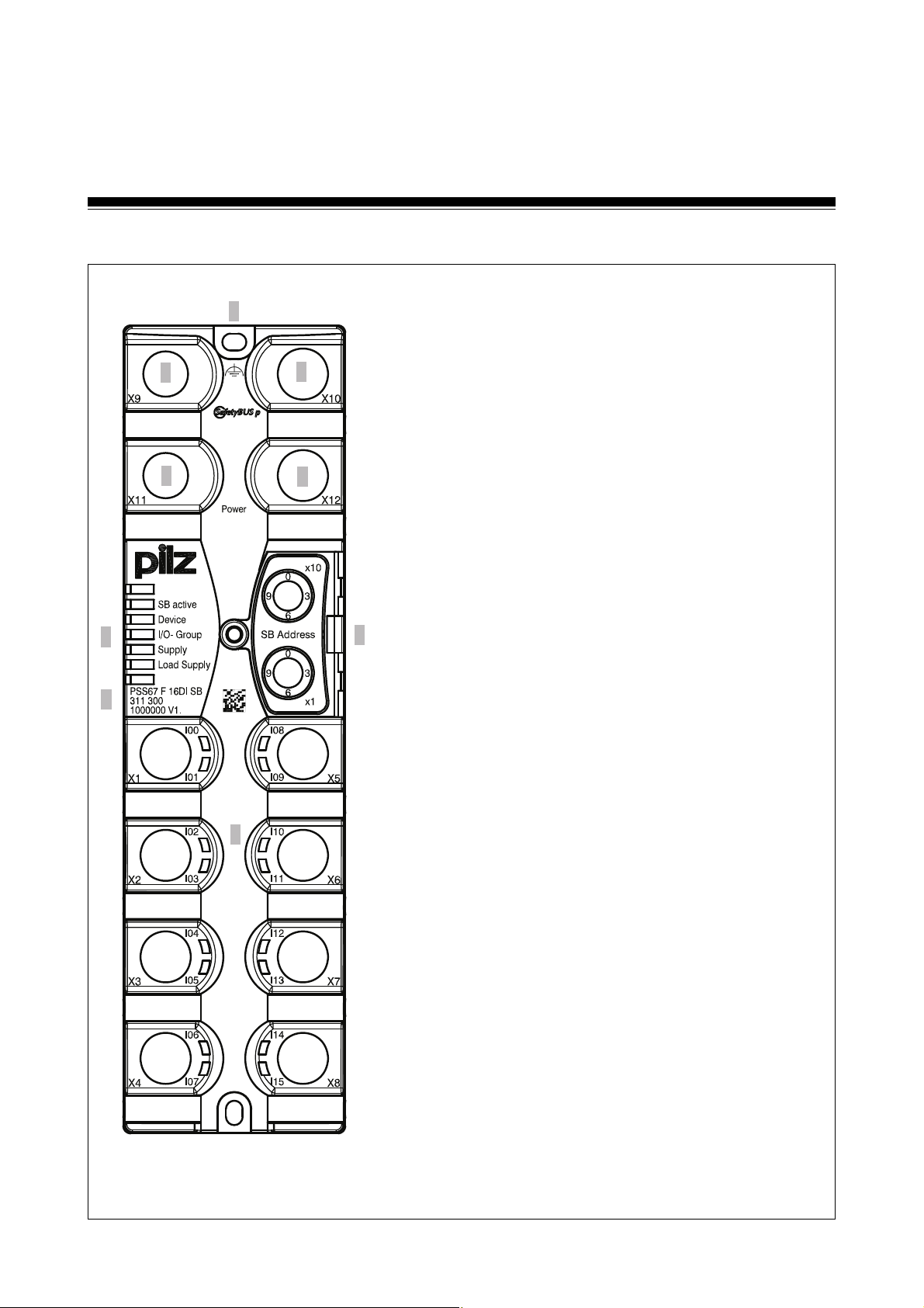
Front view
8
1
3
5
9
1
2
4
6
1: SafetyBUS p IN interface X9 (M12 male
connector)
2: SafetyBUS p OUT interface X10 (M12 female
connector)
3: Supply voltage connection IN
X11 (M12 male connector)
7
4: Supply voltage connection OUT
X12 (M12 female connector)
5: LEDs for operating status and
voltage supply
6: Rotary switch for setting the device address
on SafetyBUS p
7: Plug-in connectors for inputs and
test pulse outputs X1 to X8 (M12 female
connectors)
8: Functional earth connection
9: Labelling strip with:
•Device type
•Order number
•Serial number/hardware version
Fig. 2-1: Front view
2-2 Operating Manual: PSS67 F 16DI SB-T
Page 13

Safety
Intended use
The PSS67 F 16DI SB-T is a decentralised input module designed for use
on SafetyBUS p, where it has the function of an “Input/Output Device”.
The following is deemed improper use:
• Any component, technical or electrical modification to the digital input
module
• Use of the digital input module outside the areas described in this
manual
• Use of the digital input module outside the documented technical details
(see chapter entitled “Technical Details”).
3-1Operating Manual: PSS67 F 16 DI SB-T
Page 14

Safety
Categories in accordance with EN 954-1
WARNING!
Please note: To achieve the corresponding category or requirement class,
the whole system including all safety-related components (parts, devices,
user program etc.) must be included in the assessment. For this reason,
Pilz cannot accept liability for the correct classification into a category or
requirement class.
Digital inputs
Depending on the application area and its respective regulations, the
inputs may be used without test pulses for applications up to Category 3,
in accordance with EN 954-1. The possibility of a short circuit occurring in
the external wiring between different inputs or against the supply must be
eliminated through appropriate wiring.
For Category 4 applications, shorts between the input contacts must be
detected. This can be achieved through the use of the module’s test pulses
or, depending on the type of input device, through a feasibility test or
through detection of shorts across the contacts on the input device (e.g.
light grid) (for connection examples please see “Wiring the Inputs and
Outputs”).
System requirements
CPU versions
The PSS67 F 16DI SB-T is supported by the following SafetyBUS pcompatible programmable safety and control systems:
• PSS SB CPU from Version 1.3
• PSS1 SB CPU from Version 1.3
• PSS SB 3006 IBS-S PCP from Version 1.2
• PSS SB 3056 from Version 1.2
• PSS(1) SB CPU3 from Version 1.4
• all Compact 3rd Generation PSS, e.g. PSS SB 3047-3 ETH-2
3-2 Operating Manual: PSS67 F 16DI SB-T
Page 15

System software versions
The following system software is required in order to configure the module:
• PSS WIN-PRO from Version 1.7.0
Safety guidelines
Failure to keep to the following safety regulations will render all warranty
and liability claims invalid:
• All health and safety / accident prevention regulations for the particular
area of application must be observed.
• Before using the unit it is necessary to perform a safety assessment in
accordance with the Machinery Directive 98/37/EC.
Use of qualified personnel
The safety system may only be assembled, installed, programmed,
commissioned, operated, maintained and decomissioned by qualified
personnel. Qualified personnel are people who, because they are:
EMCD
• Qualified electrical engineers and
• Have received training from qualified electrical engineers,
are suitably experienced to operate devices, systems, plant and machinery
in accordance with the general standards and guidelines for safety
technology.
The module PSS67 F 16DI SB-T is designed for use in an industrial
environment. Interference may occur if used within a domestic environment.
3-3Operating Manual: PSS67 F 16 DI SB-T
Page 16

Safety
Warranty and liability
All claims to warranty and liability will be rendered invalid if:
• The module PSS67 F 16DI SB-T was used contrary to the purpose for
which it was intended
• Damage can be attributed to not having followed the guidelines in the
manual
• Operating personnel are not suitably qualified
• Any type of modification has been made (e.g. exchanging components
on the PCB boards, soldering work etc.).
Disposal
The module PSS67 F 16DI SB-T must be disposed of properly when it
reaches the end of its service life.
3-4 Operating Manual: PSS67 F 16DI SB-T
Page 17

Function Description
Inputs
Single and dual-channel input devices can be connected to the inputs, with
or without test pulses. The inputs are equipped with input filters.
Input signals must show a “High” (“1” signal) of 15 VDC (+15 ... +30 VDC)
and a “Low” (“0” signal) of 0 VDC (-3 ... +5 VDC).
The input status is signalled to the CPU on the controlling PSS via
SafetyBUS p. Green LEDs indicate the status of the inputs. An LED lights
up as soon as a “1” signal is present at the input.
Diagnostic circuitry checks the function of the inputs and the input filter. If
an error is detected, all the outputs in the affected I/O-Group are shut down
and the I/O-Group switches to a STOP condition. The module then triggers
an error telegram on SafetyBUS p and stores the error in its error buffer.
Where test pulses are not used, inputs with single-channel input devices
can be used in applications up to and including Category 2 in accordance
with EN 954-1; in the case of dual-channel input devices, this extends to
Category 3 applications. The possibility of a short circuit occurring in the
external wiring between different inputs or against the supply must be
eliminated through appropriate wiring.
Test pulses must be used for applications with single-channel input
devices above Category 2 and for applications with dual-channel input
devices above Category 3.
Connection examples can be found in the chapter entitled: “Wiring the
Inputs and Test Pulse Outputs”.
The inputs can be assigned to two I/O-Groups. Please refer to the section
entitled “Setting the device address”.
Operating Manual: PSS67 F 16DI SB-T
4-1
Page 18

Function Description
Signal detection at the inputs
To guarantee that a signal at an input (“0” signal or “1” signal) is detected, it
must be present for a certain time period. This period must be longer than
the event timeout configured in the PSS WIN-PRO system software. Once
a signal has been detected, a corresponding event telegram will be
triggered.
A signal (“0” signal or “1” signal) is ignored if it does not exceed the pulse
suppression time of 300 µs. In this case, no event telegram is triggered.
U
"1"-Signal
"0"-Signal
t1: Pulse duration to guarantee signal detection for “1” signals or “0” signals
(> Event Timeout)
t2: Max. pulse duration for pulse suppression with “1” signals or “0” signals
(300 µs)
Fig. 4-1: Signal detection at the inputs
Signal change behaviour
If a signal at an input changes, the module will send an event telegram.
The module must then wait for a confirmation telegram (ACK) from the
Master LD before it can send out a new event telegram.
If there is another signal change while the module is waiting for the
telegram, the module’s behaviour will depend on the configured signal
change behaviour.
t
1
t
1
t
2
t
4-2 Operating Manual: PSS67 F 16DI SB-T
Page 19

Two behaviour modes can be configured in the software’s configurator:
• “default”:
The signal changes are not registered.
• “Fast”:
Each signal change is temporarily stored in a FIFO telegram buffer. Once
the confirmation telegram arrives, the module sends consecutive event
telegrams for each detected signal change from the FIFO telegram buffer.
Test pulse outputs/24 VDC pins
The four test pulse outputs T0 to T3 may only be used for test pulses or as
24 VDC outputs.
The test pulse outputs are suitable for testing the wiring of input devices.
All safety-related inputs must operate in accordance with the failsafe
principle (on switching off).
Two test pulses are available on each plug-in connector; these test pulses
are permanently assigned to the inputs. The assignment of the test pulses
to the inputs cannot be changed in the system software’s configurator.
If the test pulse outputs are not being used, they can be configured as
24 VDC pins in the system software’s configurator (default setting).
Internal wiring diagram
The diagram on page 4-4 shows an internal wiring diagram of the
PSS67 F 16DI SB-T.
Operating Manual: PSS67 F 16DI SB-T
4-3
Page 20

Function Description
I
0
I
15
24 V DC
24 V DC
Test
Test
I
15
I
14
I
13
I
12
I
11
I
10
I
9
I
8
I
7
I
6
I
2
I
4
I
3
I
2
I
1
I
1
T
3
0
1
0
0
T3 / 24 V DC
T3 / 24 V DC
T2 / 24 V DC
T2 / 24 V DC
T1 / 24 V DC
/ 24 V DC
1
T
0
0
1
0
T
1
T
/ 24 V DC
0
/ 24 V DC
T
0
1
T
3
0
1
24 V DC
0
1
T
0
0
1
24 V DC
0
3,3 nF
1,2 M
OUT
CPU
(2-channel)
IN
DC
DC
5 V
24 V
Fig. 4-2: Internal wiring diagram of the PSS67 F 16DI SB-T
3,3 nF
3,3 nF
T3 / 24 V DC
T3 / 24 V DC
T2 / 24 V DC
T2 / 24 V DC
T1 / 24 V DC
/ 24 V DC
T
1
T
/ 24 V DC
0
/ 24 V DC
T
0
Ground
Ground
Supply
4-4 Operating Manual: PSS67 F 16DI SB-T
Page 21

Installation
Caution!
Electrostatic discharge can damage components on the
PSS67 F 16DI SB-T.
Ensure against discharge before touching the module, e.g. by touching an
earthed, conductive surface or by wearing an earthed armband.
The unit must be fastened to a flat mounting surface, so that there is no
strain on the housing when the module is screwed down. The mounting
distances will depend on which plug-in connectors are used and the
bending radius of the cables
To install the system, proceed as follows:
• Drill 2 x M4 holes (internal thread) in the mounting surface, as shown in
• Connect the functional earth to the upper fixing screw. If the functional
Fig. 5-1 (tolerance: ± 0.2 mm/0.01").
earth cannot be connected to the upper fixing screw, you will need to
connect the functional earth to Pin 5 of the M12 connector for the supply
voltage.
• Use two fixing screws to attach the module to the mounting plate.
Operating Manual: PSS67 F 16DI SB-T 5-1
Page 22

Installation
(1.18")
(0.18")
(2.36")
(8.1")
35.5 (1.4")
(1")
(8.46")
(1.18")
(0.18")
Fig. 5-1: Installing the PSS67 F 16DI SB-T, dimensions stated in mm (")
5-2 Operating Manual: PSS67 F 16DI SB-T
Page 23

Supply Voltage
Please note the following:
• When selecting the power supply, please refer to the requirements stated
under “Technical Details”.
• Overvoltage or interference voltage can damage or even destroy the
electronics on the PSS67 F 16DI SB-T. If this occurs, the affected I/OGroups will switch to a STOP condition and all the outputs in the affected
groups will be switched off. You should therefore take note of the relevant
EMC measures.
• WARNING!
Safe electrical isolation must be ensured for the external 24 V supply.
Failure to do so could result in electric shock. Power supplies must
conform to EN 60950, section 2.3, EN 60742 or EN 50178.
• To achieve the lowest possible residual ripple, we recommend that you
install a three-phase bridge rectifier or regulated supply.
• The “Ground” connection to the earth bar or earth fault monitor must be in
accordance with the relevant national regulations (e.g. EN 60204-1,
NFPA 79:17-7, NEC: Article 250).
INFORMATION
The module’s output circuits have been designed to guarantee maximum
safety. To achieve this, extensive tests are carried out internally.
Momentary interruptions to the “Supply” voltage during a test procedure
can falsify the test result, causing the following malfunction:
If the “Supply” voltage is interrupted momentarily, the unbuffered test pulse
outputs will transmit a “0” signal. The buffered module electronics reads
this signal at the pulsed inputs, thereby triggering the user's programmed
reaction. Example: The system reacts as though an E-STOP button has
been operated, although this is not the case: there has been a supply
interruption.
Remedy: “Supply” must be buffered.
Operating Manual: PSS67 F 16DI SB-T
6-1
Page 24

Supply Voltage
Use a 5-pin M12 plug-in connector to connect the module to the external
supply voltage.
The module also has an M12 socket which is physically next to the M12
connector; this is used to distribute the supply voltage to other modules.
SafetyBUS p
Supply
Fig. 6-1: Example for the supply and the forwarding of the supply voltages
Supply
WARNING!
The current carrying capacity of the M12 connectors is 4 A per contact.
Exceeding the permissible current carrying capacity may lead to connector
damage. Please note that the connection for the outgoing supply voltage
is not monitored for overload
6-2 Operating Manual: PSS67 F 16DI SB-T
Page 25

Functional earth
You can connect the functional earth to the upper fixing screw or to Pin 5 of
the M12 connector for the supply voltage.
INFORMATION
We recommend that you connect the functional earth to the upper fixing
screw.
3
4
X11(male connector) X12(female connector)
Fig. 6-2: Pin assignment for the supply voltage
Operating Manual: PSS67 F 16DI SB-T
55
2
2
1
1
3
1: + 24 VDC
2: Reserved for output devices
3: O V
4: Reserved for output devices
5: Functional earth
4
6-3
Page 26

Supply Voltage
Notes
6-4 Operating Manual: PSS67 F 16DI SB-T
Page 27

Wiring
Wiring the inputs and test pulse outputs
2
5
1
Fig. 7-1 Pin assignment of the inputs and test pulses
3
1: Test pulse X /24 V DC
2: Input X
3: 0 V
4: Input X+1
5: Test pulse X+1/ 24 V DC
4
This chapter describes the safety-related wiring of the digital inputs plus
the test pulse outputs.
CAUTION!
In order to guarantee protection type IP67, unused connectors should be
sealed using the blind plugs supplied.
CAUTION!
Make sure that the plug-in connectors are connected to the input devices
correctly. Once you have run a function test to check that the connectors
are connected to the input devices correctly, the inputs should be labelled.
If the inputs are connected to the input devices incorrectly, life-threatening
situations may arise on the plant.
INFORMATION
We recommend you use ready-made connectors to connect the inputs and
test pulse outputs.
INFORMATION
Please refer to the technical details for information on the maximum cable
runs when connecting input devices.
Operating Manual: PSS67 F 16DI SB-T 7-1
Page 28

Wiring
Notes on wiring
Where safety-related applications are concerned, it is essential that short
circuits and open circuits are unable to cause a hazardous condition within
a plant.
WARNING!
Safe separation is required when connecting a device with a circuit with
over 25 V AC or 60 V DC
The following terms are important:
• Signal inputs with frequent operation
These are signals that change status on several occasions within a
period of time.
• Single-channel safe input devices
These are positively-driven, normally-closed contacts which open on
actuation (failsafe principle).
• Elimination of short circuits between signals
This is possible within electrically-enclosed areas and also outside
electrically-enclosed areas for signals conducted in different multicore
cables. However, all components must meet the relevant regulations in
accordance with EN, DIN and VDE.
• In principle, the possibility of earth faults and open circuits cannot be
eliminated. With multi-channel input devices with frequent operation,
short circuits and open circuits can be detected via feasibility checks in
the control program.
The input test on the module uses test pulses to enable the operating
program of the PSS67 F 16DI SB-T to carry out a test to detect open
circuits and short circuits. The following pages contain details of
connection examples which may be of use when wiring the unit.
Labelling the module
You can label the SafetyBUS p and supply voltage connections, as well as
the inputs. 12 blank labels are supplied with the module. In addition you
can order a DIN A4 sheet with 264 labels as an accessory (order
no. 331 250).
7-2 Operating Manual: PSS67 F 16DI SB-T
Page 29

Digital inputs
Features:
• 16 digital inputs I0 ... I
• The inputs are connected using 8 5-pin M12 plug-in connectors. Two
inputs are available on each M12 plug-in connector.
• Only input signals that operate in accordance with the failsafe principle
(on switching off) are permitted for safety-related applications.
• Signals may be connected using unshielded cables.
Test pulse outputs
Features:
• 4 test pulse outputs T
• The assignment of test pulses to inputs is permanently specified and
cannot be configured using the system software’s configurator.
• Test pulses cannot be addressed via the PSS process I/O-image.
• Test pulses must only be used for test signals.
• Identical test pulses within a test pulse group (see Fig. 7.4) can take a
maximum 250 mA load. If you use all the test pulses, the maximum
permitted current load per plug-in connector and test pulse is 125 mA.
15
to T
0
3
Operating Manual: PSS67 F 16DI SB-T 7-3
Page 30

Wiring
Test pulse group 1
Test pulse group 2
T0
2 x 125 mA
T2 T3
2 x 125 mA
T1
2 x 125 mA
2 x 125 mA
I0 I1
T0 T1
I2 I3
T0 T1
I4 I5
T2 T3
I6 I7
T2 T3
I0 I1
T0 T1
I8 I9
T0 T1
I10 I11
T0 T1
I12 I13
T2 T3
I14 I15
T2 T3
2 x 125 mA
T0 T1
2 x 125 mA
T2 T3
2 x 125 mA
2 x 125 mA
Test pulse group 3
Test pulse group 4
Fig. 7-2 Current load on the test pulses
7-4 Operating Manual: PSS67 F 16DI SB-T
Page 31

Example: Single-channel, failsafe input device, without test pulse
Features:
• Depending on the application area and its respective regulations, this
connection diagram is suitable for input devices with frequent and
infrequent operation in accordance with EN 954-1, up to Category 2.
The possibility of a short circuit occurring in the external wiring between
different inputs or against the supply must be eliminated through
appropriate wiring.
• The input device must be approved for failsafe applications.
• Please read the instructions provided with the input device.
CAUTION!
A short circuit in the cable between the input device and input with the 24
VDC line or between adjacent input devices will not be detected.
Depending on the type of input device connected, this could create a risk to
both personnel and machinery (e.g. E-STOP). Always ensure that the unit
is suitably wired to eliminate the risk of short circuits.
Operating Manual: PSS67 F 16DI SB-T 7-5
Page 32

Wiring
Example: Single-channel, failsafe input device, without test pulse
L-
24 V
L+
Single-channel,
failsafe input device
Please ensure safety regulations and EMC guidelines are met!
Test pulse T0
I0 I1
T0 T1
I2 I3
T0 T1
I4 I5
T2 T3
I6 I7
T2 T3
I8 I9
T0 T1
I10 I11
T0 T1
I12 I13
T2 T3
I14 I15
T2 T3
7-6 Operating Manual: PSS67 F 16DI SB-T
Page 33

Example: Dual-channel input devices, without test pulses
Features:
• This type of connection is mainly used for signal inputs with frequent
operation.
• Depending on the application area and its respective regulations, this
connection diagram is suitable for input devices with frequent operation
and diverse channels, up to Category 4 in accordance with EN 954-1,
provided the functionality of both input device channels is monitored in
the user program via a feasibility check.
• Depending on the application area and its respective regulations, this
connection diagram is suitable for input devices with infrequent
operation up to Category 3 in accordance with EN 954-1, provided the
functionality of both input device channels is monitored in the user
program via a feasibility check.
• If you are using input devices with different (diverse) channels, adjacent
inputs may be used. Short circuits will be detected in the user program
via the feasibility check (see example in the PSS-Range Programming
Manual).
CAUTION!
A short circuit in the cable between the input device and input with the
24 VDC line or between adjacent input devices will not be detected.
Depending on the type of input device connected, this could create a risk to
both personnel and machinery (e.g. E-STOP). Always ensure that the unit
is suitably wired to eliminate the risk of short circuits.
Operating Manual: PSS67 F 16DI SB-T 7-7
Page 34

Wiring
Example: Dual-channel input devices, without test pulses
L-
24 V
L+
Dual-channel input
device with different
(diverse) channels
Please ensure safety regulations and EMC guidelines are met!
24 V
24 V
I0 I1
T0 T1
I2 I3
T0 T1
I4 I5
T2 T3
I6 I7
T2 T3
I8 I9
T0 T1
I10 I11
T0 T1
I12 I13
T2 T3
I14 I15
T2 T3
7-8 Operating Manual: PSS67 F 16DI SB-T
Page 35

Example: Single-channel, failsafe input device, with test pulse
Features:
• Depending on the application area and its respective regulations, this
connection diagram is suitable for applications up to Category 2 in
accordance with EN 954-1.
• The input device must be approved for failsafe applications.
• Please read the instructions provided with the input device.
• Short circuits between the cable from the test pulse to the input device
and the cable from the input device to the input will not be detected.
• Only input devices with N/C contacts can be tested.
Operating Manual: PSS67 F 16DI SB-T 7-9
Page 36

Wiring
Example: Single-channel, failsafe input device, with test pulse
L-
24 V
L+
Singlechannel,
failsafe input
device
Single-channel,
failsafe input
device with
supply voltage
from the test
pulse
0
24
S21
S11
A1
Test pulse T0
A2
12 22
I0 I1
T0 T1
I2 I3
T0 T1
I4 I5
T2 T3
I6 I7
T2 T3
I8 I9
T0 T1
I10 I11
T0 T1
I12 I13
T2 T3
I14 I15
T2 T3
Please ensure safety regulations and EMC guidelines are met!
7-10 Operating Manual: PSS67 F 16DI SB-T
Page 37

Example: Dual-channel, failsafe input device, with test pulse
Features:
• Depending on the application area and its respective regulations, this
connection diagram is suitable for applications up to Category 4 in
accordance with EN 954-1.
• This type of connection is mainly used for signal inputs with infrequent
operation.
• On input devices with identical channels, each channel should be given
a separate test pulse, where possible. This will ensure that all short
circuits are detected, with the exception of short circuits which short out
the input device (cable from the test pulse to the input device and cable
from the input device to the input).
• If the input device has only one test pulse, a short circuit between the
cables from the input device to the inputs will not be detected. In this
case the unit should be suitably wired to avoid the risk of this type of short
circuit. If diverse input devices are used, this type of error will be
detected.
Operating Manual: PSS67 F 16DI SB-T 7-11
Page 38

Wiring
Example: Dual-channel, failsafe input device, with test pulse
L-
24 V
L+
Dual-channel input device
with diverse channels
Dual-channel input device
with identical channels
Please ensure safety regulations and EMC guidelines are met!
Test pulse T1
Test pulse T0
Test pulse T1
Test pulse T0
I0 I1
T0 T1
I2 I3
T0 T1
I4 I5
T2 T3
I6 I7
T2 T3
I8 I9
T0 T1
I10 I11
T0 T1
I12 I13
T2 T3
I14 I15
T2 T3
7-12 Operating Manual: PSS67 F 16DI SB-T
Page 39

SafetyBUS p Interface
The module is connected to SafetyBUS p using a 5-pin A-coded M12
connector (X9). A 5-pin A-coded M12 socket (X10) is available to distribute
the bus signal to the other bus subscribers.
The X10 socket can also be used for bus subscriber termination.
To avoid reflection on the bus cable, the last bus subscriber must be fitted
with a terminating resistor. If the module is connected using 1:1 connection
cable, the terminating resistor is plugged into the free X10 socket . The
M12 terminator (Order no. 311 032) PSS SB M12 TERMINATOR is used
for termination via the SafetyBUS p socket.
55
4
X9 (male connector) X10 (female connector)
Fig. 8-1 Pin assignment of the SafetyBUS p interface
23
2
1
1
3
1: Shield
2: n.c.
3: CAN_GND (white)
4: CAN_H (green)
5: CAN_L
n.c. = not connected
4
8-1Operating Manual: PSS67 F 16DI SB-T
Page 40

SafetyBUS p Interface
Notes
8-2 Operating Manual: PSS67 F 16DI SB-T
Page 41

Operation and Maintenance
Operation and maintenance
Commissioning
• Install the digital input module as described in the chapter entitled
“Installation” on page 5-1.
• Connect the inputs and outputs as described in the chapter entitled
“Wiring the Inputs and Outputs” on page 7-1.
• Connect the supply voltage for the digital input module as described in
the chapter entitled “Supply Voltage” on page 6-1.
• Connect SafetyBUS p
• Set the device address.
• Configure the module using the system software’s configurator
9-1Operating Manual: PSS67 F 16DI SB-T
Page 42

Operation and Maintenance
Setting the device address
In order to operate the module on SafetyBUS p you will need to set the
device address that was defined for the module in the system software’s
configurator.
To do this you will need to use a screwdriver to open the transparent cover
on the rotary switches.
Use the rotary switches to set the required address. The rotary switch
labelled “x1” is used to set the units and the rotary switch labelled “x10” is
used to set the tens.
Permitted device addresses are in the range 32D ... 95D. The same applies
if the module is configured for SafetyBUS p 1 in the
SafetyBUS p Configurator on the PSS WIN-PRO system software. The
offset of 100D for device addresses on SafetyBUS p 1 is calculated
automatically from the bus configuration.
Rotary switch
"SB Address"
x10
x1
The I/O-Groups to which the module belongs must also be defined in the
system software’s configurator.
The module can be divided into sections A and B for this purpose. Section
A and section B may belong to different I/O-Groups. The module may either
have section A alone, section B alone, or both section A and section B. The
inputs can be assigned to both sections at will.
Membership of section A or section B is used in conjunction with the
device address to form the addresses under which the inputs can be
addressed by the controlling PSS.
Key
Set the tens
Set the unit
Example:
Device address 51D
In the process image of the controlling PSS, the inputs from Section A are
addressed under the device address as slot number and bit number
9-2 Operating Manual: PSS67 F 16DI SB-T
Page 43

0 ... 15. The inputs from Section B are addressed under the device address
as slot number and bit number 16 ... 31; this corresponds to an offset of 16
in the bit number.
So if input I6 from Section A is reconfigured into Section B, for example, the
address will change from x.06 to x.22.
Example: Device address is 36
Input Section Address Input Section Address
I
0
I
1
I
2
I
3
I
4
I
5
I
6
I
7
A E36.00 I
A E36.01 I
B E36.18 I
B E36.19 I
B E36.20 I
A E36.05 I
A E36.06 I
A E36.07 I
8
9
10
11
12
13
14
15
A E36.08
A E36.09
A E36.10
A E36.11
A E36.12
B E36.29
B E36.30
B E36.31
WARNING!
Any errors made when setting the device address will result in the loss of
the safety function.
If the same device address is set on two modules or the device addresses
of two modules are transposed, the controlling PSS may unknowingly
address the wrong inputs/outputs.
This will cause the plant to malfunction. The safe operation of the plant is
no longer guaranteed.
To avoid this, the greatest possible care must be taken when setting the
device addresses.
The device address may not be modified while the module is being
operated on SafetyBUS p (“SB active” LED lights up green or flashes),
otherwise all the I/O-Groups configured on the module will switch to a
STOP condition.
If it is necessary to change the set device address while the bus is running,
you will need to disconnect the module from SafetyBUS p while you make
the change. When you re-establish the connection to SafetyBUS p, the
module will quickly be ready for operation again (“Device” LED lights up
green).
9-3Operating Manual: PSS67 F 16DI SB-T
Page 44

Operation and Maintenance
Display elements
Status LEDs
Each input is assigned a status LED (I00 to I15).
The corresponding LED will light when its respective input has the status
“1”, otherwise it will remain unlit.
“Supply” LED
Indicates the presence of the supply voltage, “Supply”.
“Device” LED
This dual-colour LED indicates the device status.
• Red: A device error has occurred. The device error may involve one or
both of the I/O-Groups configured on the module.
• Flashing red: There is a periphery error.
• Green: The module is operating without error.
• LED off: A system error is preventing the module from starting up.
“SB active” LED
Indicates the presence of a connection between the module and the
Management Device.
• Green: Connection to the Management Device has been established
• LED off: No contact with SafetyBUS p (faulty wiring or Management
Device not in operation)
• Flashing green: There is contact with SafetyBUS p, but the Management
Device does not recognise the module (faulty device address or
configuration)
“I/O-Group” LED
Indicates the status of the I/O-Groups configured on the module.
• Green: All I/O-Groups configured on the module have “RUN” status
• LED off: All I/O-Groups configured on the module have “STOP” status
• Flashing green: One of the I/O-Groups configured on the module has
“STOP” status.
9-4 Operating Manual: PSS67 F 16DI SB-T
Page 45

“Load Supply” LED
Reserved for output devices
Recommissioning
NOTICE
When recommissioning, errors may occur when plugging in the connectors
as there is no protection against them being inserted incorrectly. Always
carry out a function test when recommissioning to ensure you exclude the
possibility of such an error.
Faults
If the module is defective or there is a wiring error, all the outputs in the
affected I/O-Group are shut down and the I/O-Group switches to a STOP
condition. An error telegram is then triggered on SafetyBUS p and the error
is entered in the error buffer of the PSS67 F 16DI SB-T.
An error message appears on the display of the controlling PSS. The error
stack display in the programming device can be used to locate the error
(see “SafetyBUS p System Description”).
Module configuration
The procedure for configuring SafetyBUS p and the module PSS67 F 16DI
SB-T is described in the online help of the PSS WIN-PRO system software.
9-5Operating Manual: PSS67 F 16DI SB-T
Page 46

Operation and Maintenance
Notes
9-6 Operating Manual: PSS67 F 16DI SB-T
Page 47

Technical Details
Electrical data
Supply voltage 24 VDC
Voltage tolerance -15 %/+20 %
Residual ripple DC 5%
Current consumption 90 mA plus load currents taken from the
test pulse outputs
Galvanic isolation Yes, between inputs and
SafetyBUS p
Connection B-coded M12 connector
SafetyBUS p
Transmission rate Max. 500 kBit/s
Cable runs Max. 3500 m
Transmission type Differential two-wire cable
Connection A-coded M12 connector
Digital inputs
Number of inputs 16
Type according to 61101-2 24 VDC Type 1
Separation of supply Yes, between inputs and SafetyBUS p
“1” Signal +15 ... +30 VDC
“0” Signal -3 ... +5 VDC
Input current Typ. 3.5 mA
Input delay < 1 ms
Pulse suppression < 300 µs
Status indicator Green LED
Dedicated test pulses
Number 4 (configurable in pairs as test pulse or
24 VDC output)
Output current at “1” signal Max. 0.125 A per pin
Total load capacity Max. 0.25 A per test pulse group
Cable runs Between test pulse output and input
Max. 100 m
10-1Operating Manual: PSS67 F 16DI SB-T
Page 48

Technical Details
Environmental data
Protection type (EN 60529) IP67
Mounting position Any
Climatic suitability EN 60068-2-1, EN 60068-2-2,
EN 60068-2-14
Ambient temperature
(EN 60068-2-14) -40 ... +60 °C
Storage temperature (EN 60068-2-1/-2) -40 ... +70 °C
EMC EN 61000-4-2, EN 61000-4-3, EN 61000-4-4,
EN 61000-4-5, EN 61000-4-6, EN 61000-6-2,
EN 61000-6-4
Vibration (EN 60068-2-6) 10 ... 150 Hz, 1g
10 ... 55 Hz, 0,35 mm
Shock (EN 60068-2-27) 15g, 11 ms
(EN 60068-2-29) 10g, 16 ms
Mechanical data
Weight 500 g
Dimensions (H x W x D) 215 x 60 x 35,5 mm
The names of products, goods and technologies used in this manual are trademarks of the respective companies.
The standards current on 2007/10 apply.
Order reference
Description Order No.
Marking labels (264 pcs.) 311 250
Cover for unused male connectors 311 252
Cover for unsed female connectors 311 251
10-2 Operating Manual: PSS67 F 16DI SB-T
Page 49

10-3Operating Manual: PSS67 F 16DI SB-T
Page 50

Technical Details
10-4 Operating Manual: PSS67 F 16DI SB-T
Page 51

...
In many countries we are
represented by our subsidiaries
and sales partners.
Please refer to our Homepage
for further details or contact our
headquarters.
Pilz GmbH & Co. KG
Sichere Automation
Felix-Wankel-Straße 2
73760 Ostfildern, Germany
Telephone: +49 711 3409-0
Telefax: +49 711 3409-133
E-Mail: pilz.gmbh@pilz.de
www
www.pilz.com
Technical support
+49 711 3409-444
21 869-01, 2007-12 Printed in Germany
 Loading...