

Page 1

1002909-EN-02
PSEN op Protective Column 2-4/1
Operating Manual
General
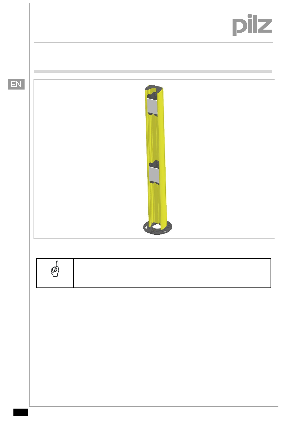
PSEN op Protective Column 2-4/1 is a column made of aluminium
and a base plate made of steel. The base plate consists of 2 plates
that can be adapted to the ground.
Deviation mirrors are already installed in the protective column.
They can be aligned independently of each other.
Overview
Features
Protects the installed deviation mirrors from accidental shock and
collisions.
One-piece profile made of coated aluminium with various lengths,
matching all height of PSEN op 2/4B (500 – 1200 mm).
Robust base plate consists of 2 plates, with pins for
compensating unevenness (levelling) and slot holes for angular
adjustment.
Spherical spirit level for easier level alignment.
Typical application areas
The accessories of PSEN op Protective Column 2-4/1 are
particularly suited for environments where vehicles such as forklifts
or automated guided vehicles can move freely.
Pilz GmbH & Co. KG, Felix-Wankel-Straße 2, 73760 Ostfildern, Germany 1
Telephone: +49 711 3409-0, Telefax: +49 711 3409-133, E-Mail: pilz.gmbh@pilz.de Original document
Page 2
1002909-EN-02
PSEN op Protective Column 2-4/1
Operating Manual
NOTICE
Fig. 1
In case the product is used for body protection the specifications of the directive EN
ISO 13855 "Positioning of safeguards with respect to the approach speeds of
parts of the human body" must be observed.
2 Pilz GmbH & Co. KG, Felix-Wankel-Straße 2, 73760 Ostfildern, Germany
Telephone: +49 711 3409-0, Telefax: +49 711 3409-133, E-Mail: pilz.gmbh@pilz.de Original document
Page 3
1002909-EN-02
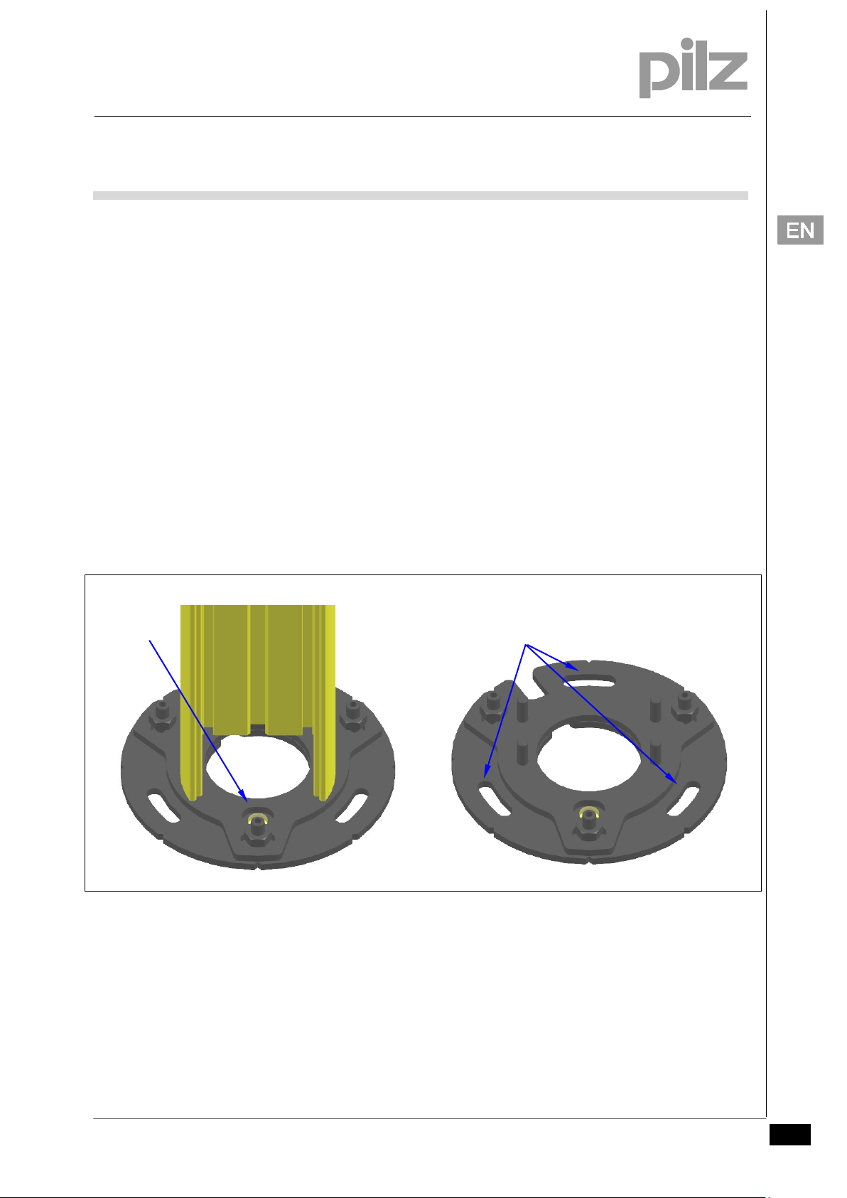
Slot holes for
Spirit level
PSEN op Protective Column 2-4/1
Operating Manual
Assembly
The profile of PSEN op Protective Column 2-4/1 is supplied with
pre-installed deviating mirrors and does not require mechanical
installation.
Levelling and angular adjustment of the plates
The grooves on the base plate are used to define the required angle
position. Tighten the slot holes on the bottom plate with the screws
M10 on the floor (not entirely). Slightly loosen the counter nuts on
the top plate and align any unevenness using the spirit level. Then
fix the screws M10 completely. Finally, check again whether the
protective column is straight, readjust if necessary and tighten the
counter nuts again (Fig. 2).
Fig. 2
bottom screws
Pilz GmbH & Co. KG, Felix-Wankel-Straße 2, 73760 Ostfildern, Germany 3
Telephone: +49 711 3409-0, Telefax: +49 711 3409-133, E-Mail: pilz.gmbh@pilz.de Original document
Page 4
1002909-EN-02
PSEN op Protective Column 2-4/1
Operating Manual
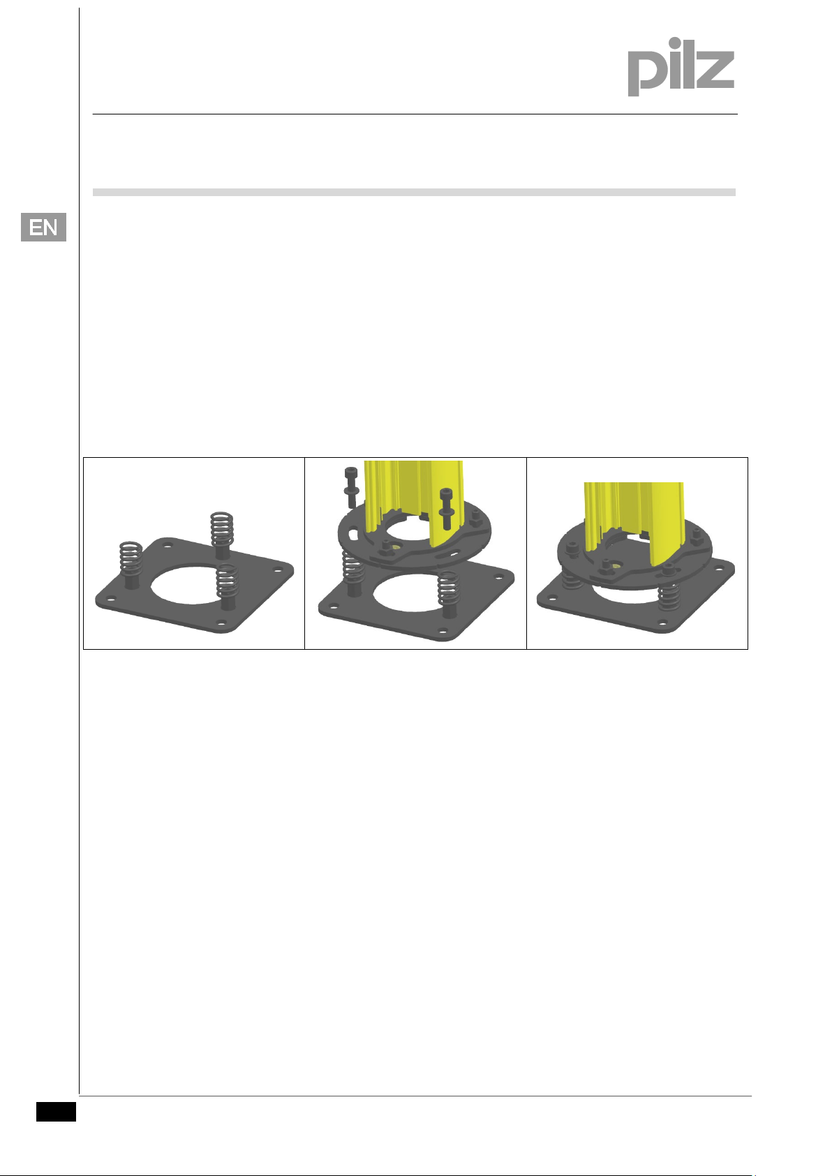
Installing the PSEN op Protective Base/1 accessories
Screw the additional plate to the floor and mount the 3 springs on
the spacers. Fix the protective column with the base plate so that
the slot holes of the bottom plate are right above the springs. Insert
the screws M10 together with the washers (PSEN op Protective
Base/1 accessories) into the slot holes and compress the 3 springs
equally when affixing the screws (Fig. 3). Align the protective
column as described in "Levelling and angular adjustment of the
plates".
The optimum working height of the springs (distance between base
plate and additional plate) is ca. 42 mm.
Fig. 3
4 Pilz GmbH & Co. KG, Felix-Wankel-Straße 2, 73760 Ostfildern, Germany
Telephone: +49 711 3409-0, Telefax: +49 711 3409-133, E-Mail: pilz.gmbh@pilz.de Original document
Page 5

1002909-EN-02
Screws M8x12
Screws M4x20
Screws M8x12
PSEN op Protective Column 2-4/1
Operating Manual
Aligning the deviating mirrors
To adjust the height of the deviating mirrors loosen the screws
M5x12 and position the deviating mirrors in the protective column as
required. Then tighten the screws again. If the protective column is
in vertical position, make sure that the deviating mirrors do not slip
downward.
The 3 screws M4x20 are used to level the deviation mirrors (Fig.4).
Pilz GmbH & Co. KG, Felix-Wankel-Straße 2, 73760 Ostfildern, Germany 5
Telephone: +49 711 3409-0, Telefax: +49 711 3409-133, E-Mail: pilz.gmbh@pilz.de Original document
Fig. 4
Page 6

1002909-EN-02
Number of mirrors
Operating range
Operating range
Transmitter
deviating
mirrors
deviating
mirrors
Receiver
PSEN op Protective Column 2-4/1
Operating Manual
Use of a deviating mirror reduces the effective operating range by
about 15%. This percentage increases further when using two or
three deviating mirrors.
In the table below the operating ranges are indicated, based on
the number of the mirrors used.
Without mirror 6 m 19 m
1 5.1 m 16.5 m
2 4.3 m 13.7 m
3 3.7 m 11.6 m
Installing PSEN op Protective Column 2-4/1 with PSEN op Mirror/1
Fig. 5
6 Pilz GmbH & Co. KG, Felix-Wankel-Straße 2, 73760 Ostfildern, Germany
Telephone: +49 711 3409-0, Telefax: +49 711 3409-133, E-Mail: pilz.gmbh@pilz.de Original document
Define the area to be protected and the exact positions where the
deviating mirrors, the transmitter and receiver units of the light
curtain are to be installed. The "Order reference" table combines
the recommended pairs of product and corresponding accessory.
Fix the PSEN op Protective Column 2-4/1 on the floor in the
required position. When using an additional plate (PSEN op
Protective Base/1) perform the installation as described in the
"Installing the PSEN op Protective Base/1 accessories" section.
Page 7

1002909-EN-02
ith PSEN op
4/1. The tolerances can be compensated by levelling and
angular adjustments of the protective columns and the laser pointer. Do not
PSEN op Protective Column 2-4/1
Operating Manual
Align the deviating mirror to ca. 45° to the optical path. PSEN op
Protective Column 2-4/1 allows regulation around the vertical axis
by +/- 5° (s. section "Levelling and angular adjustment of the
plates").
Position the laser pointer at the upper part of the transmitter unit
and align the unit so that the laser beam is horizontal in the
middle of the first deviating mirror. The height of the laser pointer
and the height where the pointer hits have to be identical.
Repeat the procedure and align the laser pointer at the bottom
part of the unit. Repeat these steps several times, if necessary.
Align the first deviation mirror so that the laser beam hits the
second deviating mirror in the position described before.
The laser pointer has mechanical tolerances when combined w
NOTICE
Protective Column 2-
compensate the tolerances by changing the deviating mirror position.
Pilz GmbH & Co. KG, Felix-Wankel-Straße 2, 73760 Ostfildern, Germany 7
Telephone: +49 711 3409-0, Telefax: +49 711 3409-133, E-Mail: pilz.gmbh@pilz.de Original document
Page 8

1002909-EN-02
PSEN op2B-2-050
PSEN op4B-2-050
PSEN opSB-4B-2-050
PSEN op2B-3-080
PSEN op4B-3-080
PSEN opSB-4B-3-080
PSEN op2B-4-090
PSEN op4B-4-090
PSEN opSB-4B-4-090
PSEN op2B-4-120
PSEN op4B-4-120
PSEN opSB-4B-4-120
PSEN op Protective Column 2-4/1
Operating Manual
Order reference
PSEN op Protective Column 2-4/1
Product type Description Order no.
PSEN op Protective Column 2-050/1 Protective Stand 2 mirror H500 630961
PSEN op Protective Column 3-080/1 Protective Stand 3 n mirror H800 630962
PSEN op Protective Column 4-090/1 Protective Stand 4 mirror H900 630963
PSEN op Protective Column 4-120/1 Protective Stand 4 mirror H1200 630964
Table of suitable light curtains
Product type Light curtain
PSEN op Protective Column 2-050/1
PSEN op Protective Column 3-080/1
PSEN op Protective Column 4-090/1
PSEN op Protective Column 4-120/1
The preceding table only includes the models of the PSEN op 2/4B ranges. The
NOTICE
PSEN op Protective accessories can also be used with the light curtains of the
PSEN op 2/4xx ranges.
Accessories
Product type Description Order no.
PSEN op Protective Base/1
Double plate with compensation
springs
630955
8 Pilz GmbH & Co. KG, Felix-Wankel-Straße 2, 73760 Ostfildern, Germany
Telephone: +49 711 3409-0, Telefax: +49 711 3409-133, E-Mail: pilz.gmbh@pilz.de Original document
Page 9

1002909-EN-02
PSEN op Protective Column 2-4/1
Operating Manual
Dimensions
Base plate and additional plate:
Fig. 6
Pilz GmbH & Co. KG, Felix-Wankel-Straße 2, 73760 Ostfildern, Germany 9
Telephone: +49 711 3409-0, Telefax: +49 711 3409-133, E-Mail: pilz.gmbh@pilz.de Original document
Page 10

1002909-EN-02
PSEN op Protective Column 2-4/1
Operating Manual
PSEN op Protective Column 2-050/1
PSEN op Protective Column 3-080/1
PSEN op Protective Column 4-090/1
10 Pilz GmbH & Co. KG, Felix-Wankel-Straße 2, 73760 Ostfildern, Germany
Telephone: +49 711 3409-0, Telefax: +49 711 3409-133, E-Mail: pilz.gmbh@pilz.de Original document
Page 11

1002909-EN-02
PSEN op Protective Column 2-4/1
Operating Manual
PSEN op Protective Column 4-120/1
Pilz GmbH & Co. KG, Felix-Wankel-Straße 2, 73760 Ostfildern, Germany 11
Telephone: +49 711 3409-0, Telefax: +49 711 3409-133, E-Mail: pilz.gmbh@pilz.de Original document
 Loading...