

Page 1

1002904-EN-03
Number of mirrors
Operating range
Operating range
PSEN op Mirror/1
Operating Manual
Safety guidelines
We recommend that you never use more than 3 deviation mirrors
along the light axis to ensure correct functionality.
To maintain correct functionality of the system we recommend
that you regularly clean the surface of the deviating mirror with a
damp soft cloth. Cleaning intervals depend on the environmental
conditions of the system.
The length of the deviating mirror must be at least 100 mm
greater than the length of the protected field of the light curtain.
The deviating mirror must be installed in a way that its axes
(horizontal and vertical) correspond to the respective axes of the
light curtains.
The deviating mirror has to be fixed, so that it cannot be
displaced accidentally or by strong vibrations.
We recommend that you use the PSEN op Protective Column/1
accessories where the deviating mirror can be fixed with the
corresponding assembly kits.
In an environment with strong temperature differences and/or
shocks we recommend to use the PSEN op Mirror Bracket Kit/1.
As the width of the deviating mirror is limited, the reaction of the
entire system is particularly sensitive to turns on the vertical axis
of the deviating mirror and the transmitter and receiver units.
Therefore, particular care is required when aligning the system
and fixing the parts.
We recommend that you use the laser pointer to make the
system installation (deviating mirror and light curtain) easier.
Use of a deviating mirror reduces the effective operating range by
about 15%. This percentage increases further when using two or
three deviating mirrors.
Pilz GmbH & Co. KG, Felix-Wankel-Straße 2, 73760 Ostfildern, Germany 1
Telephone: +49 711 3409-0, Telefax: +49 711 3409-133, E-Mail: pilz.gmbh@pilz.de Original document
In the table below the operating ranges are indicated, based on
the number of the mirrors used.
Without mirror 6 m 19 m
1 5.1 m 16.5 m
2 4.3 m 13.7 m
3 3.7 m 11.6 m
Page 2
1002904-EN-03
Transmitter
deviating
mirrors
deviating
mirrors
Receiver
PSEN op Mirror/1
Operating Manual
Assembly
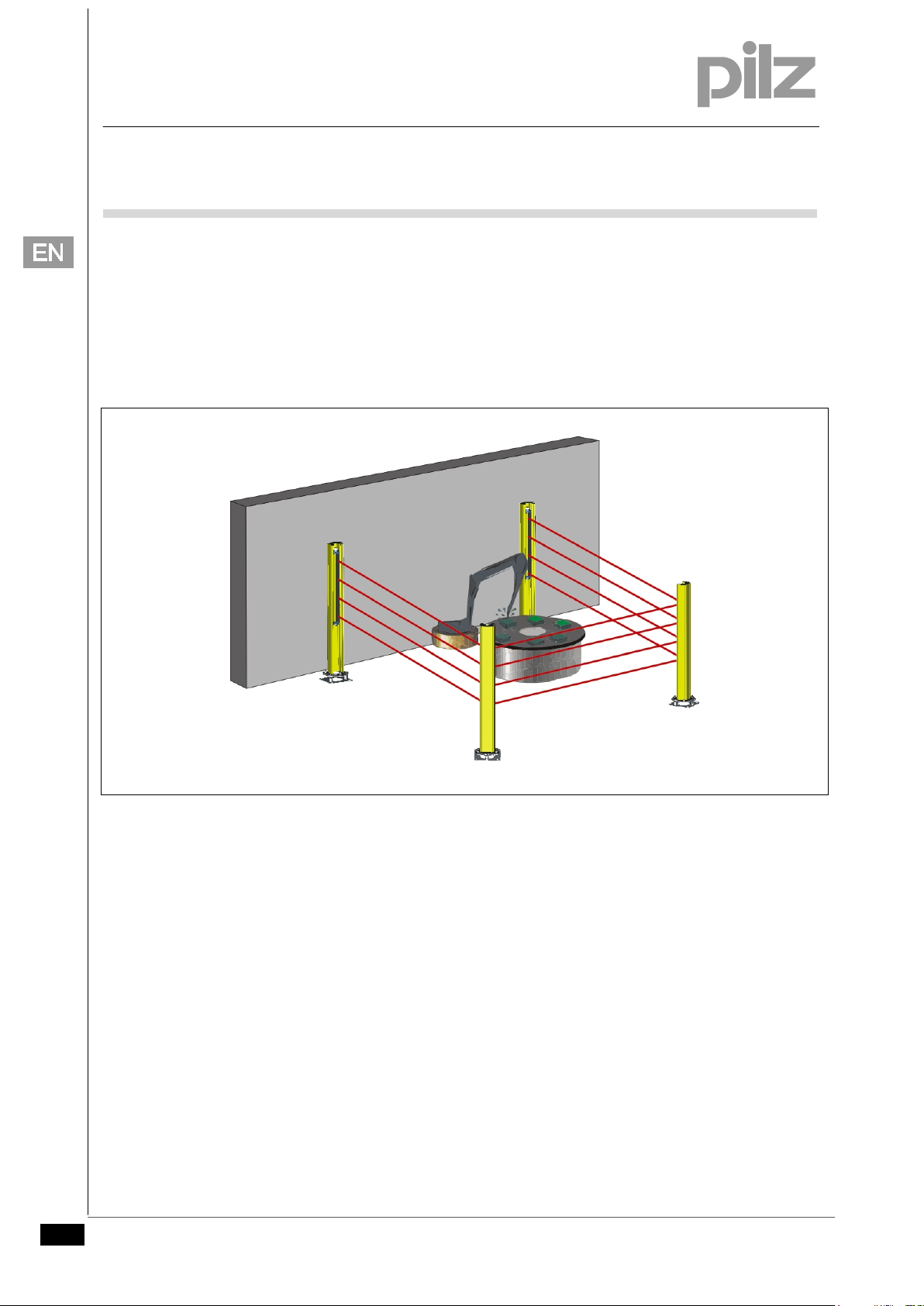
Fig. 1 shows a protection system that consists of a light curtain and
two deviating mirrors. The alignment of deviating mirrors is
explained in the following sections based on this example.
Stand-alone installation
Fig. 1
The mounting bracket kit PSEN op Mirror Bracket Kit/1 and a floor
bracket are required for installation.
Define the area to be protected and the exact positions where the
deviating mirrors and the transmitter and receiver units of the light
curtain are to be installed.
Fix the floor bracket to the defined point on the floor and note that
their axes have to be aligned vertically.
Install the deviating mirrors at the floor brackets, and the
transmitter and receiver units, taking into account the notes
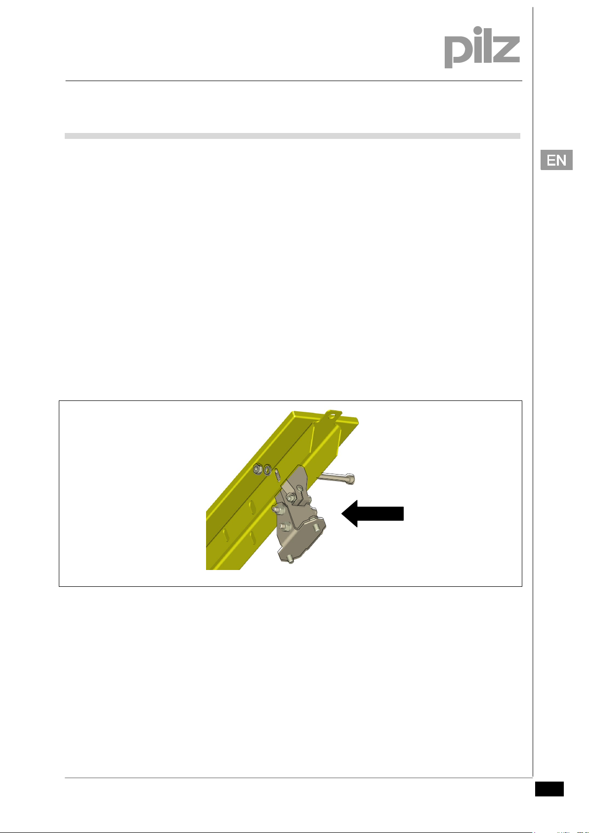
above. Insert the screw M6x50 into the slot hole of the rail, then
screw it in with the corresponding washer and nut (Fig. 2) to
install the mounting bracket at the deviating mirrors.
Align the deviating mirror to ca. 45° to the optical path.
Position the laser pointer at the upper part of the transmitter unit
and align the unit so that the laser beam is horizontally in the
2 Pilz GmbH & Co. KG, Felix-Wankel-Straße 2, 73760 Ostfildern, Germany
Telephone: +49 711 3409-0, Telefax: +49 711 3409-133, E-Mail: pilz.gmbh@pilz.de Original document
Page 3
1002904-EN-03
PSEN op Mirror Bracket Kit/1
Screw M6x50
PSEN op Mirror/1
Operating Manual
middle of the first deviating mirror. The height of the laser pointer
and the height where the pointer hits have to be identical.
Repeat the procedure and align the laser pointer at the bottom
part of the unit. Repeat these steps several times, if necessary.
Align the first deviation mirror so that the laser beam hits the
second deviating mirror in the position described before.
Turn the mounting brackets to set the angle, an when the
required position is reached, tighten the screws. Use the slot
holes at the deviating mirror and/or adapt the inclination of the
floor bracket by adding adjusting washers.
Align the second deviating mirror in the same way and make sure
that the laser hits the receiver unit.
Insert the laser pointer in the upper part of the receiver unit and
align it so that the laser beam reflected by the deviating mirrors
hits the transmitter unit.
Repeat the same process with the laser pointer in the lower part
of the receiver unit.
Pilz GmbH & Co. KG, Felix-Wankel-Straße 2, 73760 Ostfildern, Germany 3
Telephone: +49 711 3409-0, Telefax: +49 711 3409-133, E-Mail: pilz.gmbh@pilz.de Original document
Fig. 2
Page 4
1002904-EN-03
4/1 for the
PSEN op Mirror/1
Operating Manual
Installation on PSEN op Protective Column/1
The various PSEN op Mirror/1 can be installed on the PSEN op
Protective Column/1.
PSEN op Protective Column/1 is a column made of aluminium and a
base plate made of steel. The base plate consists of 2 plates that
can be adapted to the ground.
Please refer to the operating manual PSEN op Protective Column/1
for the installation.
The PSEN op Protective Column 2-4/1 is pre-assembled for PSEN op Mirror-015/1.
NOTICE
See the operating manual on PSEN op Protective Column 2corresponding settings and installation.
4 Pilz GmbH & Co. KG, Felix-Wankel-Straße 2, 73760 Ostfildern, Germany
Telephone: +49 711 3409-0, Telefax: +49 711 3409-133, E-Mail: pilz.gmbh@pilz.de Original document
Page 5

1002904-EN-03
Product type
Light curtain
PSEN op2B-2-050
PSEN op4B-2-050
PSEN opSB-4B-2-050
PSEN op2B-3-080
PSEN op4B-3-080
PSEN opSB-4B-3-080
PSEN op2B-4-090
PSEN op4B-4-090
PSEN opSB-4B-4-090
PSEN op2B-4-120
PSEN op4B-4-120
PSEN opSB-4B-4-120
PSEN op xx-s-xx-015/1
PSEN op xx-s-xx-030/1
PSEN op xx-s-xx-045/1
PSEN op xx-s-xx-060/1
PSEN op xx-s-xx-075/1
PSEN op xx-s-xx-090/1
PSEN op xx-s-xx-105/1
PSEN op xx-s-xx-120/1
PSEN op xx-s-xx-135/1
PSEN op xx-s-xx-150/1
PSEN op xx-s-xx-165/1
PSEN op xx-s-xx-180/1
er than the length
PSEN op Mirror/1
Operating Manual
Order reference
Table of suitable light curtains
2x PSEN op Mirror-015/1
3x PSEN op Mirror-015/1
4x PSEN op Mirror-015/1
PSEN op Mirror-060/1
PSEN op Mirror-090/1
PSEN op Mirror-120/1
PSEN op Mirror-165/1
PSEN op Mirror-190/1
NOTICE
Pilz GmbH & Co. KG, Felix-Wankel-Straße 2, 73760 Ostfildern, Germany 5
Telephone: +49 711 3409-0, Telefax: +49 711 3409-133, E-Mail: pilz.gmbh@pilz.de Original document
Please note the length of the deviating mirror!
The length of the deviating mirror must be at least 100 mm great
of the protected field of the light curtain.
Page 6

1002904-EN-03
PSEN op Mirror/1
Operating Manual
Dimensions
PSEN op Mirror-015/1
Fig. 3 shows PSEN op Mirror-015/1 with installed PSEN op Mirror
Bracket Kit/1.
Fig. 3
6 Pilz GmbH & Co. KG, Felix-Wankel-Straße 2, 73760 Ostfildern, Germany
Telephone: +49 711 3409-0, Telefax: +49 711 3409-133, E-Mail: pilz.gmbh@pilz.de Original document
Page 7

1002904-EN-03
Product type
L1 (mm)
L2 (mm)
L3 (mm)
PSEN op Mirror/1
Operating Manual
PSEN op Mirror/1
Fig. 4 shows PSEN op Mirror/1 in the length 60 - 190 cm with
installed
PSEN op Mirror Bracket Kit/1.
NOTICE
PSEN op Mirror-060/1 545 376 580
PSEN op Mirror-090/1 845 676 880
PSEN op Mirror-120/1 1145 976 1180
PSEN op Mirror-165/1 1595 1426 1630
PSEN op Mirror-190/1 1845 1676 1880
Fig. 4
Please refer to the operating manual PSEN op Protective Column/1 for the
protective columns matching the deviating mirrors PSEN op Mirror/1.
Pilz GmbH & Co. KG, Felix-Wankel-Straße 2, 73760 Ostfildern, Germany 7
Telephone: +49 711 3409-0, Telefax: +49 711 3409-133, E-Mail: pilz.gmbh@pilz.de Original document
 Loading...