

Page 1
PSEN op2H
Sicherheitslichtgitter
Safety light curtains with infrared beams
Barrière de sécurité à rayons infrarouges
Barreras de Seguridad
Barriera di sicurezza a raggi infrarossi
BEDIENUNGSANLEITUNG
OPERATING MANUAL
MANUEL D'UTILISATION
INSTRUCCIONES DE USO
MANUALE PER L’USO
Page 2

A Pilz Ges.m.b.H., 01 7986263-0, Fax: 01 7986264, E-Mail: pilz@pilz.at AUS Pilz Australia Industrial
Automation LP., 03 95446300, Fax: 0395446311, E-Mail: safety@pilz.com.au
3217570, Fax: 09 3217571, E-Mail: info@pilz.be
4337-1241, Fax: 11 4337-1242, E-Mail: pilz@pilzbr.com.br
Fax: 062 88979-40,E-Mail: pilz@pilz.ch
pilz@pilz.dk
France Electronic, 03 88104000, Fax: 03 88108000, E-Mail: siege@pilz-france.fr
09 27093700, Fax: 09 27093709, E-Mail: pilz.fi@pilz.dk
Fax: 01536 460866, E-Mail: sales@pilz.co.uk
info@pilz.it
E Pilz lndustrieelektronik S.L., 938497433, Fax:938497544, E-Mail: pilz@pilz.es F Pilz
IRL Pilz Ireland Industrial Automation, 021 4346535, Fax: 021 4804994, E-Mail:sales@pilz.ie
BR Pilz do Brasil Sistemas Eletr¶nicosIndustriais Ltda., 11
CH Pilz lndustrieelektronik GmbH, 062 88979-30,
DK Pilz Skandinavien K/S, 74436332, Fax: 74436342, E-Mail:
GB Pilz Automation Technology, 01536 460766,
I Pilz ltalia Srl, 031 789511, Fax: 031 789555, E-Mail:
B L Pilz Belgium, 09
FIN Pilz Skandinavien K/S,
J Pilz Japan Co., Ltd., 045 471-2281, Fax: 045 471-2283, E-Mail: pilz@pilz.co.jp MEX Pilz de Mexico,
S. de R.L. de C.V., 55 5572 1300,Fax: 55 5572 4194, E-Mail: info@mx.pilz.com
320477, Fax: 0347 320485, E-Mail: info@pilz.nl
t.catterson@pilz.co.nz
P Pilz Industrieelektronik S.L., 229407594, Fax: 229407595, E-Mail: pilz@pilz.es
NZ Pilz New Zealand, 09-6345350, Fax: 09-6345350, E-Mail:
NL Pilz Nederland, 0347
PRC PilzChina Representative Office, 021 62493031, Fax: 021 62493036, E-Mail: sales@pilz.com.cn
ROK Pilz Korea Office, 031 8159541, Fax: 031 8159542,E-Mail: info@pilzkorea.co.kr SE Pilz
Skandinavien K/S, 0300 13990, Fax: 0300 30740, E-Mail: pilz.se@pilz.dk
Ürünleri veHizmetleri Tic. Ltd. ©Sti., 0224 2360180, Fax: 0224 2360184, E-Mail: pilz.tr@pilz.de
Automation Safety L.P., 734 354-0272, Fax: 734 354-3355,E-Mail: info@pilzusa.com
TR Pilz Elektronik Güvenlik
USA Pilz
www www.pilz.com
D Pilz GmbH & Co. KG, Sichere Automation, Felix-Wankel-Straβe 2, 73760 Ostfildern, Deutschland,
+49 711 3409-0, Fax: +49 711 3409-133, E-Mail: pilz.gmbh@pilz.de
826002341 rev.A
Page 3

PSEN op2H Serie Bedienungsanleitung
1. ALLGEMEINE INFORMATIONEN............................................................................... 1
1.1. Allgemeine Beschreibung der Schutzeinrichtungen............................................ 1
1.2. Anleitung zur Auswahl der Schutzeinrichtung..................................................... 3
1.3. Typische Anwendungsbereiche .......................................................................... 5
1.4. Sicherheitsinformationen..................................................................................... 6
2 INSTALLATION............................................................................................................ 7
2.1. Vorsichtsmaßnahmen bei Auswahl und Installation der Einrichtung .................. 7
2.2. Allgemeine Informationen zur Positionierung der Einrichtung ............................ 8
2.2.1. Mindestsicherheitsabstand ................................................................... 10
2.2.2. Mindestabstand zu reflektierenden Flächen......................................... 12
2.2.3. Installation von mehreren Sicherheitslichtgittern nebeneinander ......... 14
2.2.4. Einsatz von Strahlumlenkspiegeln ....................................................... 15
3. MECHANISCHE MONTAGE...................................................................................... 16
4. ELEKTRISCHE ANSCHLÜSSE................................................................................. 18
4.1. Bemerkungen zu den Anschlüssen................................................................... 19
4.2. Zeitdiagramm der TEST-Funktion..................................................................... 20
5. AUSRICHTUNG ......................................................................................................... 23
5.1. Anleitungen für eine sachgerechte Ausrichtung (Automatischer START) ........ 23
6. START-MODUS ......................................................................................................... 25
7. DIAGNOSEFUNKTION .............................................................................................. 27
7.1. Funktionsanzeigen ............................................................................................ 27
7.2. Fehlermeldungen und Diagnose ....................................................................... 28
8. REGELMÄSSIGE KONTROLLEN UND WARTUNG ................................................ 29
8.1. Wartung............................................................................................................. 29
8.2. Allgemeine Informationen und nützliche Angaben............................................ 30
INHALTSÜBERSICHT
9. TECHNISCHE DATEN ............................................................................................... 31
10. VERZEICHNIS DER VERFÜGBAREN MODELLE.................................................... 32
11. EINBAUABMESSUNGEN.......................................................................................... 33
12. ZUBEHÖR .................................................................................................................. 34
Page 4
Bedienungsanleitung PSEN op2H Serie
1. ALLGEMEINE INFORMATIONEN
1.1. Allgemeine Beschreibung der Schutzeinrichtungen
Sicherheitslichtsgitter der PSEN op2H Serie sind optoelektronische
Schutzeinrichtungen. Sie sichern Arbeitsbereiche ab, in welchen das
Bedienpersonal mit beweglichen Teilen von Maschinen, Robotern und
ganz allgemein automatisierten Anlagen in Berührung kommen kann,
die ein Risiko der Körperverletzung bergen.
Die Sicherheitslichtgitter der Serie PSEN op2H sind als sichere
Systeme vom Typ 2 zur Unfallverhütung gemäß den geltenden
internationalen Normen konzipiert, insbesondere:
EN 61496-1: 1997 Sicherheit von Maschinen: Berührungslos
wirkende Schutzeinrichtungen. Teil 1:
Allgemeine Anforderungen und
Prüfungen.
prEN 61496-2: 1997 Sicherheit von Maschinen - Berührungslos
wirkende Schutzeinrichtungen Teil 2:
Besondere Anforderungen an
Einrichtungen, welche nach dem aktiven
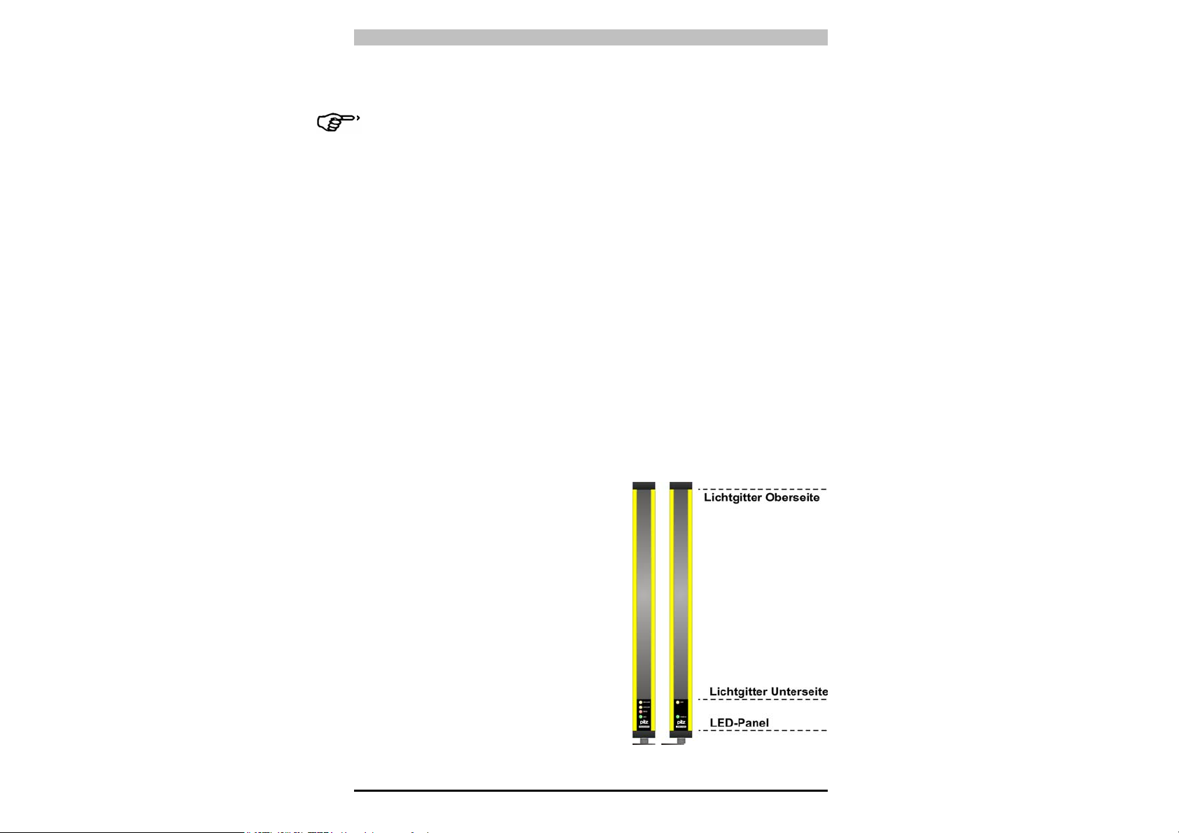
Die Einrichtung, die aus einem Sender und einem Empfänger besteht,
die in robusten Aluprofilen untergebracht sind, deckt den
Schutzbereich durch Erzeugung eines Infrarot-Schutzfeldes, definiert
durch Schutzfeldhöhe und Schutzfeldbreite, ab.
Die Steuer- und Auswertelogik
befinden sich im Innern der beiden
Einheiten; der elektrische Anschluss
erfolgt über M12-Stecker, die an der
Unterseite der Profile angebracht
sind. Sende- und Empfangseinheit
werden auf optischem Wege
synchronisiert, die beiden Einheiten
müssen nicht direkt miteinander
verbunden sein. Die Steuerung und
Überwachung der Infrarotstrahlen
erfolgt über einen Mikroprozessor,
der dem Benutzer durch LEDAnzeigen Informationen über den
Betriebszustand des Lichtgitters
liefert (siehe Kap. 7
„Diagnosefunktion“).
optoelektronischen Prinzip arbeiten.
1
Page 5
PSEN op2H Serie Bedienungsanleitung
Zwei gelbe LEDs erleichtern die Ausrichtung der beiden Einheiten
während der Installation (siehe Kap. 5 „Ausrichtung“).
Sobald die von der Sendeeinheit ausgesendeten Strahlen von einem
Gegenstand, einem Körperteil oder dem Körper des Bedienpersonals
unterbrochen werden, werden beide Ausgänge (OSSD) sofort geöffnet
und die an den OSSD angeschlossene Maschine gestoppt.
Anm.:
In diesem Handbuch werden folgende, gemäß den
geltenden Vorschriften definierte Abkürzungen verwendet:
AOPD Active opto-electronic protective device
ESPE Electro-sensible protective equipment
MPCE Machine primary control element
OSSD Output signal switching device (switching output)
TX Emission device
RX Receiving device
Einige Teile bzw. Absätze dieses Handbuchs, die für den Benutzer
oder Einrichter besonders wichtige Informationen enthalten, sind mit
folgenden Zeichen gekennzeichnet:
Detaillierte Anmerkungen und Erklärungen über besondere
Eigenschaften der PSEN op2H-Schutzeinrichtungen, um deren
Funktionsweise genauer zu erläutern.
Besondere Hinweise zur Installation.
Beachten Sie diesen Hinweis unbedingt! Er warnt Sie vor gefährlichen
Situationen, die schwerste Körperverletzungen und Tod verursachen
können und weist auf entsprechende Vorsichtsmaßnahmen hin.
In diesem Handbuch werden sämtliche Informationen gegeben, die für
die Auswahl und Funktionsweise der PSEN op2H
-
Schutzeinrichtungen
von Bedeutung sind.
Für die sachgerechte Integration eines Sicherheitslichtgitters in
kraftbetriebenen Maschinen sind besondere sicherheitsrelevante
Kenntnisse erforderlich. Da dieses Handbuch diese Kenntnisse nicht
vollständig vermitteln kann, steht der technische Kundendienst von
PILZ für sämtliche Informationen über die Funktionsweise der PSEN
op2H Sicherheitslichtgitter und die Sicherheitsvorschriften bzgl. der
korrekten Installation zur Verfügung (siehe Kap. 9 "Überprüfung und
regelmäßige Wartung").
2
Page 6
Bedienungsanleitung PSEN op2H Serie
1.2. Anleitung zur Auswahl der Schutzeinrichtung
Bei der Auswahl eines Sicherheitslichtgitters sollten drei
charakteristische Eigenschaften berücksichtigt werden:
• Auflösung
in Abhängigkeit des zu schützenden Körperteils.
Sicherheitslichtgitter der Serie PSEN op2H haben eine Auflösung
von 30mm, die für den Handschutz geeignet ist
R = 30mm Handschutz
Type 2
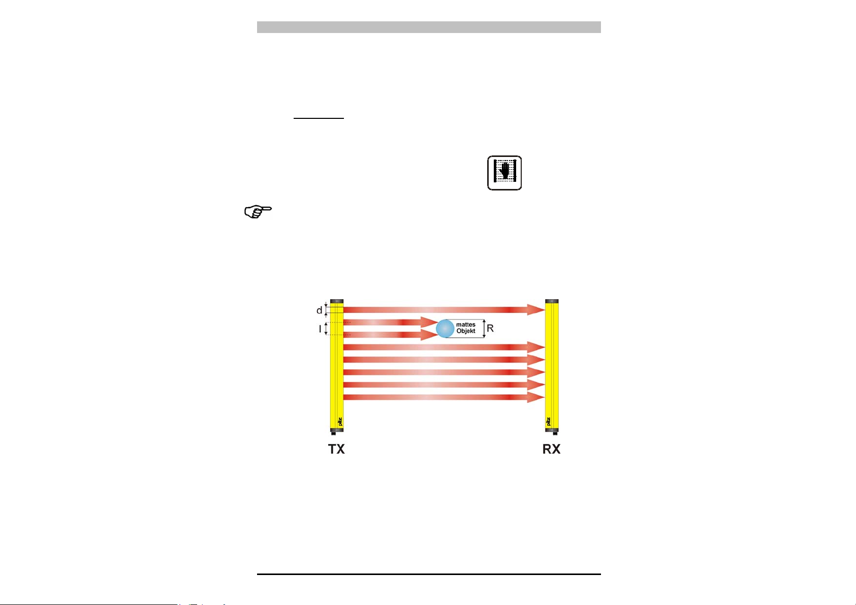
Unter Auflösung (R) des Geräts wird die Mindestgröße eines
matten Gegenstands verstanden, durch den mindestens einer der
Strahlen mit Sicherheit verdunkelt wird, die den Abstastbereich
bilden.
Wie aus Abb. 2 zu ersehen ist, hängt die Auflösung ausschließlich
von den geometrischen Eigenschaften der Linsen, dem
Durchmesser und dem Achsabstand ab, ist jedoch unabhängig von
den Umgebungs- und Betriebsbedingungen des Lichtgitters.
Der Auflösungsfaktor lässt sich nach folgender Formel berechnen:
Abb. 2
R = I + d
3
Page 7
PSEN op2H Serie Bedienungsanleitung
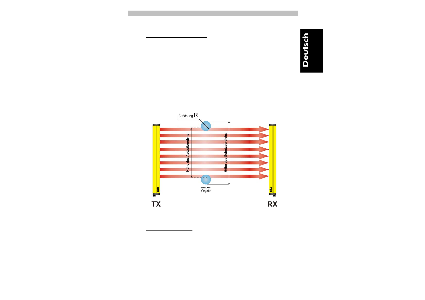
• Höhe des Schutzbereichs
Hier ist zwischen der “Höhe des Abtastbereichs” und der “Höhe
des Schutzbereichs“ zu unterscheiden (Abb. 3).
- Die Höhe des Abtastbereichs ist der Abstand zwischen dem
obersten Punkt der ersten Linse und dem untersten Punkt der
letzten Linse.
- Die Höhe des Schutzbereichs ist der effektiv abgesicherte
Bereich, in dem ein undurchsichtiges Objekt mit größeren oder
gleichen Abmessungen wie die Auflösung des Lichtgitters mit
Sicherheit die Verdunkelung eines Strahls bewirkt.
Abb. 3
• Sicherheitsabstand
Es ist sehr wichtig, die Berechnung des Abstands, mit dem die
Schutzeinrichtung zu der gefahrbringenden Maschine positioniert
werden sollte, mit besonderer Sorgfalt vorzunehmen.
(Berechnung des Sicherheitsabstands, siehe Kap. 2
“Installation”).
4
Page 8
Bedienungsanleitung PSEN op2H Serie
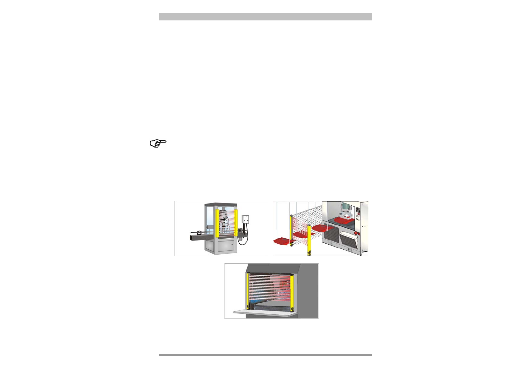
1.3. Typische Anwendungsbereiche
Sicherheitslichtgitter der PSEN op2H Serie finden in allen
Automatisierungsbereichen Anwendung, bei denen der Zugang zu
Gefahrbereichen zu kontrollieren und schützen ist.
Sie werden insbesondere eingesetzt, um gefahrbringende
Bewegungen von mechanischen Teilen zu stoppen, d.h. bei
- Automatischen Maschinen
- Verpackungs-, Handlings-, und Lagermaschinen
- Textil-, Holz-, und Keramikverarbeitungsmaschinen
- Automatischen oder halbautomatischen Montagelinien
- Automatisierten Regallagern
Bei Anwendungen im Bereich der Lebensmittelindustrie ist in
Zusammenarbeit mit dem Kundendienst von PILZ zu prüfen ob sich
das Gehäusematerial des Lichtgitters mit eventuell beim
Produktionsprozess verwendeten chemischen Stoffen verträgt.
Die folgenden Abbildungen geben einen Überblick über einige
Hauptanwendungsgebiete.
5
Page 9

PSEN op2H Serie Bedienungsanleitung
1.4. Sicherheitsinformationen
Für einen sachgerechten und sicheren Einsatz der
Schutzeinrichtungen der PSEN op2H Serie müssen folgende Hinweise
beachtet werden:
• Der Maschinenstopp muss auf elektrischem Wege steuerbar sein.
• Die Steuerung muss die gefährliche Maschinenbewegung
unverzüglich und während jeder Phase eines Arbeitsvorgangs
stoppen können.
• Die Installation des Lichtgitters und die zugehörigen elektrischen
Anschlüsse sind durch qualifiziertes Fachpersonal unter Beachtung
der in den entsprechenden Kapiteln enthaltenen Hinweise
durchzuführen (siehe Kap. 2, 3, 4, 5, 6).
• Das Lichtgitter ist so anzubringen, dass kein Zugang zum
Gefahrbereich ohne Unterbrechung der Strahlen möglich ist (siehe
Kap. 2 „Installation“).
• Personal, das im Gefahrbereich arbeitet, ist hinsichtlich der
Funktionsweise des Sicherheitsgitters entsprechend zu schulen.
• Die TEST-Taste muss außerhalb des Gefahrbereichs so
angebracht werden, dass das Bedienpersonal den Gefahrbereich
beim Durchführen von Tests vollständig einsehen kann.
6
Page 10

Bedienungsanleitung PSEN op2H Serie
2 INSTALLATION
2.1. Vorsichtsmaßnahmen bei Auswahl und Installation der Einrichtung
• Stellen Sie sicher, dass die von der Schutzeinrichtung PSEN op2H
Serie (Typ 2) garantierte Sicherheitskategorie mit der
Risikobeurteilung der zu überwachenden Maschine übereinstimmt,
wie in der Norm EN 954-1 festgelegt.
• Die Ausgänge (OSSD) der ESPE sind als
Maschinenstoppvorrichtungen und nicht als Befehlsvorrichtungen
zu verwenden (die Maschine muss über einen eigenen STARTBefehl verfügen).
• Die Abmessungen des kleinsten zu erfassenden Objekts dürfen
den Auflösungsgrad des Geräts nicht unterschreiten.
• Die Umgebung, in der das ESPE installiert wird, muss den in Kap.9
angegebenen technischen Daten des PSEN op2H Serie Lichtgitters
entsprechen.
• Installationen in der Nähe von sehr intensiven und/oder stark
blinkenden Lichtquellen sind insbesondere in der Nähe der
Empfangseinheit zu vermeiden.
• Starke elektromagnetische Störungen sollten vermieden werden,
da sie den einwandfreien Betrieb des Geräts beeinträchtigen
könnten.
• In der Arbeitsumgebung auftretender Rauch, Nebel oder Staub
kann die Reichweite der Schutzeinrichtung bis zu 50% reduzieren.
• Plötzliche auftretende Temperaturschwankungen über den
Gefrierpunkt hinaus können durch Kondensatbildungen auf den
Linsenoberflächen die einwandfreie Funktion der Schutzeinrichtung
beeinträchtigen.
7
Page 11

PSEN op2H Serie Bedienungsanleitung
2.2. Allgemeine Informationen zur Positionierung der Einrichtung
Im Hinblick auf einen effizienten Schutz ist bei der Positionierung des
Geräts besonders sorgfältig vorzugehen; insbesondere sollte das
Gerät so installiert werden, dass kein Zugang zum Gefahrbereich ohne
Schutzfeldunterbrechung möglich ist.
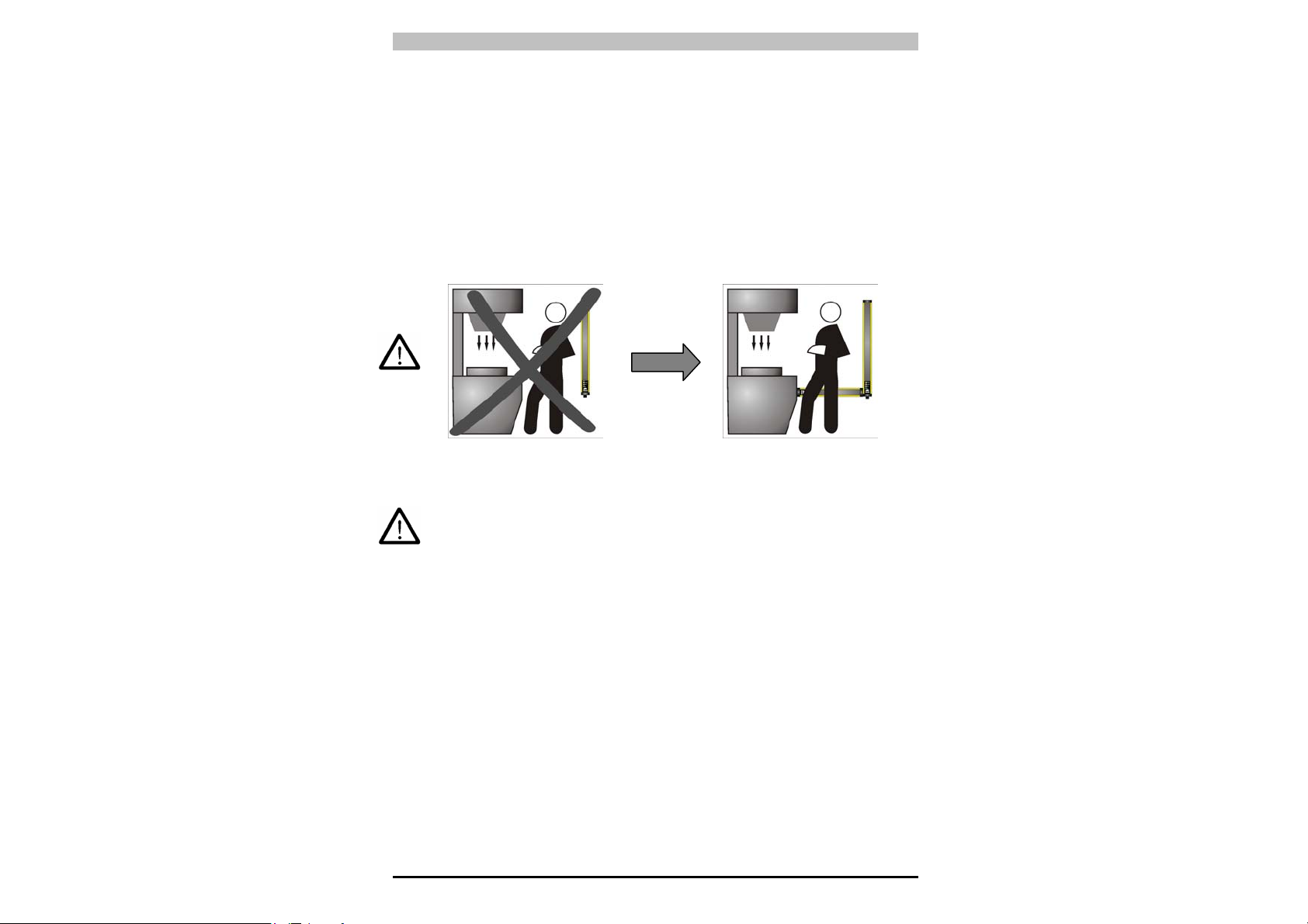
Um auszuschließen, dass die Maschine von oben oder unten
zugänglich ist (Abb. 4a), muss ein Lichtgitter mit ausreichender Länge
installiert werden, so dass der Zugang zum Gefahrbereich vollständig
abgedeckt ist (Abb. 4b).
NEIN
Abb. 4a
Abb. 4b
8
Page 12
Bedienungsanleitung PSEN op2H Serie
Außerdem darf unter normalen Betriebsbedingungen die Maschine nur
dann gestartet werden können, wenn sich das Bedienpersonal
außerhalb des Gefahrbereichs befindet.
Sollte es nicht möglich sein, das Lichtgitter in unmittelbarer Nähe des
Gefahrbereichs zu installieren, sollte ein seitlicher Zugang dadurch
ausgeschlossen werden, dass ein zweites, horizontal ausgerichtetes
Lichtgitter installiert wird, wie in Abb. 5b dargestellt.
Abb. 5a Abb. 5b
Sollte der Installationsort der Schutzeinrichtung jedoch das Betreten
des Gefahrenbereichs ermöglichen ohne dass das Schutzfeld die
entsprechende Person erfasst, ist eine zusätzliche mechanische
Absperrung notwendig, um dies zu verhindern.
9
Page 13
PSEN op2H Serie Bedienungsanleitung
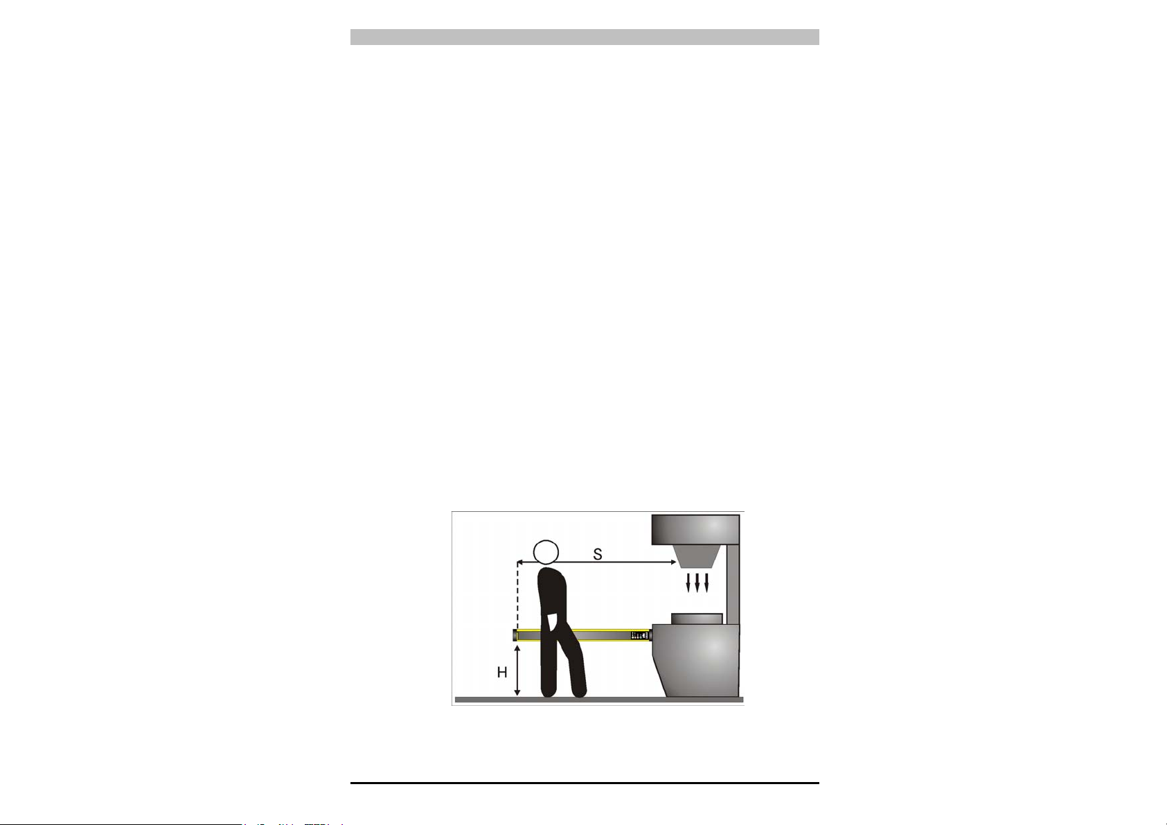
2.2.1. Mindestsicherheitsabstand
Der Sicherheitsabstand der Schutzeinrichtung ist so zu bemessen
(siehe Abb.6), dass das Bedienpersonal erst dann den Gefahrbereich
erreichen kann, wenn die Bewegung des gefahrbringenden
Maschinenteils zum Stillstand gekommen ist.
Gemäß den Normen EN-999, 775 und 294 hängt dieser Abstand von
vier Faktoren ab:
1 Ansprechzeit der ESPE (Zeit zwischen effektiver Unterbrechung
der Strahlen und Signalwechsel von High auf Low am OSSDAusgang).
2 Nachlaufzeit der Maschine (die zum Stillsetzen der Maschine
benötigte Zeit nach Ablauf der Ansprechzeit der ESPE).
3 Auflösung der ESPE.
4 Annäherungsgeschwindigkeit des zu erfassenden Objekts.
Die Formel zur Berechnung des Sicherheitsabstands lautet:
wobei
S = Mindestsicherheitsabstand zwischen Schutzfeld und Gefahrstelle in
mm
K = Annäherungsgeschwindigkeit, mit der sich das zu erfassende Objekt
(Körperteil oder Körper) dem Gefahrbereich nähert, in mm/s
t1 = Ansprechzeit des ESPE in Sekunden (Kap. 9 „Technische Daten“).
= Nachlaufzeit der Maschine in Sekunden
t
2
d = Auflösung der Schutzeinrichtung.
C = 8 (d -14) für Schutzeinrichtung mit Auflösung ≤ 40mm
= 850 mm für Schutzeinrichtung mit Auflösung > 40 mm
10
Abb. 6
S = K (t1 + t2) + C
Page 14
Bedienungsanleitung PSEN op2H Serie
Hinweis: K beträgt:
2000 mm/s, wenn der für S berechnete Wert ≤ 500 mm
1600 mm/s, wenn der für S berechnete Wert > 500 mm
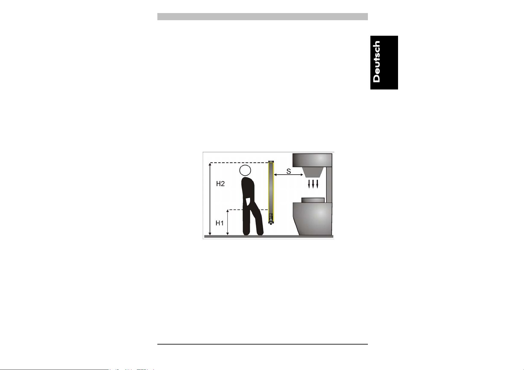
Für den Fall, dass der Gefahrbereich von oben und unten zugänglich
ist (Abb. 6) und Geräte mit einer Auflösung >40 mm benutzt werden,
muss der obere Strahl, ausgehend von der Bezugsebene (z.B.
Maschinenuntergrund), in einer Höhe von 900 mm (H2) und der untere
Strahl in einer Höhe von 300 mm (H1) positioniert werden.
Für den Fall, dass das Lichtgitter horizontal zu installieren ist (Abb. 7),
muss dies so erfolgen, dass der Abstand zwischen Gefahrbereich und
dem am weitesten von diesem Bereich entfernten optischen Strahl
gleich dem Ergebnis der nachfolgenden Formel ist:
S = 1600 mm/s (t
+ t2) + 1200 – 0.4 H
1
wobei
S = Mindestsicherheitsabstand zwischen Schutzfeld und
Gefahrstelle in mm
t
= Ansprechzeit des ESPE in Sekunden (Kap. 9 „Technische
1
Daten“).
t
= Nachlaufzeit der Maschine in Sekunden
2
H = Höhe der Strahlen über dem Boden. Diese Höhe muss immer
kleiner als 1000 mm sein.
Abb. 7
11
Page 15
PSEN op2H Serie Bedienungsanleitung
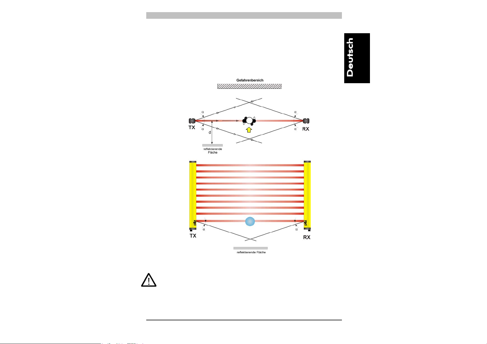
2.2.2. Mindestabstand zu reflektierenden Flächen
Reflektierende Flächen, die sich nahe der ausgehenden Lichtstrahlen
der Sicherheitseinrichtung befinden (oberhalb, unterhalb oder seitlich),
können zu passiven Reflexionen führen und die Erfassung des Objekts
innerhalb des Schutzbereiches beeinträchtigen (Abb .8).
Abb. 8
Eine nicht sachgemäße Installation könnte zur Nichterkennung von
Schutzfeldunterbrechung und damit zu ernsthaften Verletzungen
führen.
12
Page 16
Bedienungsanleitung PSEN op2H Serie
Halten Sie deshalb bei der Installation in der Nähe reflektierender
Flächen (Metallwände, -böden, -decken oder -werkstücke) unbedingt
den wie in Abb.9 grafisch dargestellten Mindestabstand zu
reflektierenden Flächen ein.
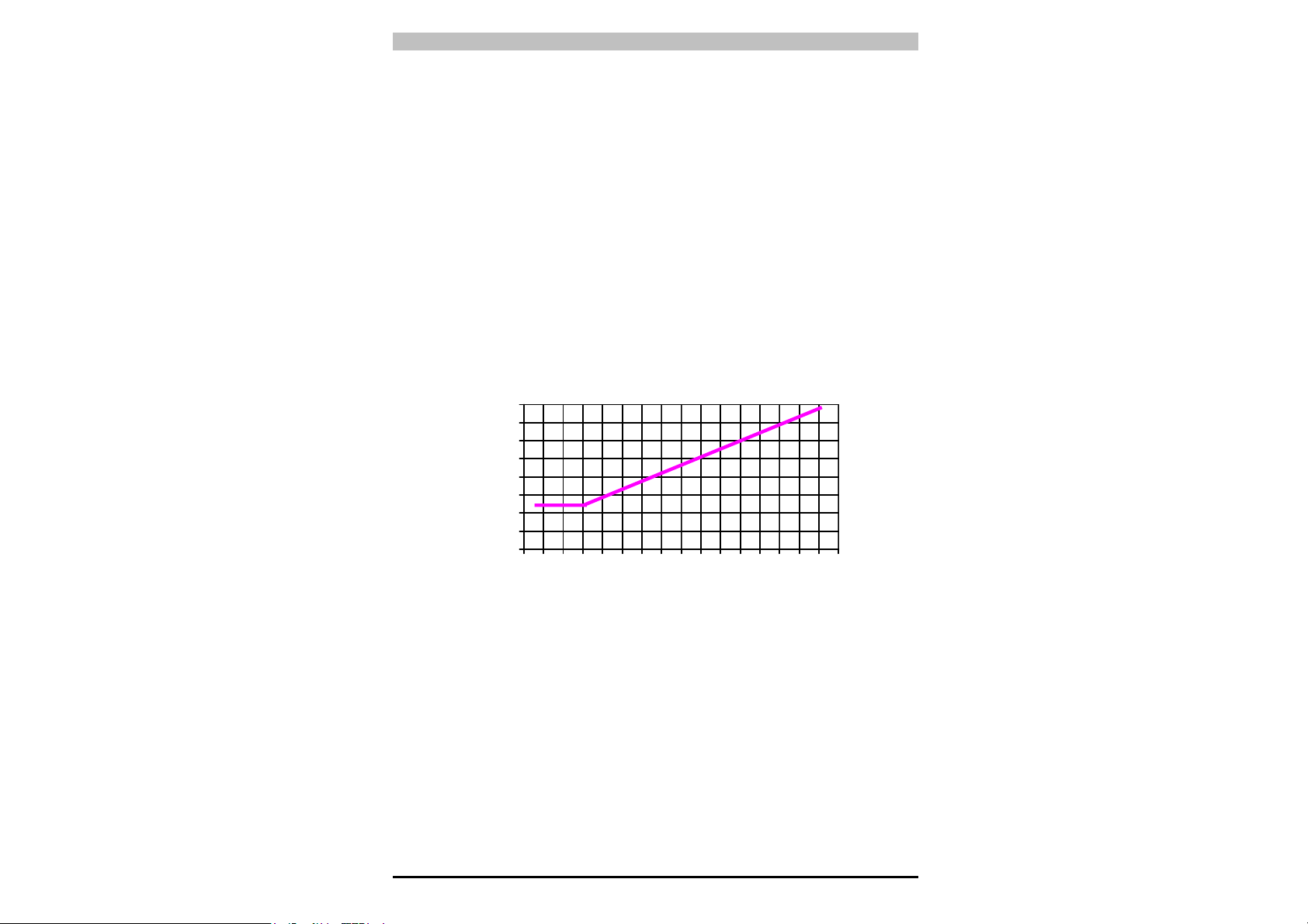
Dieser Mindestabstand hängt ab von:
• Reichweite zwischen Sender (TX) und Empfänger (RX)
• maximaler Öffnungswinkel der vom Sender ausgesendeten
Lichtstrahlen, insbesondere
- 10° für ESPE vom Typ 2 (± 5° zur Lichtachse)
Die Werte für den Mindestabstand in Abhängigkeit von der Reichweite
sind der grafischen Darstellung in Abb. 9 zu entnehmen.
800
700
600
500
400
300
200
100
0
Abstand reflektierende Fläche (mm)
0 1 2 3 4 5 6 7 8 9 10 11 12 13 14 15 16
Reichweite (m)
ESPE
vom Typ 2
Abb. 9
13
Page 17
PSEN op2H Serie Bedienungsanleitung
AJA
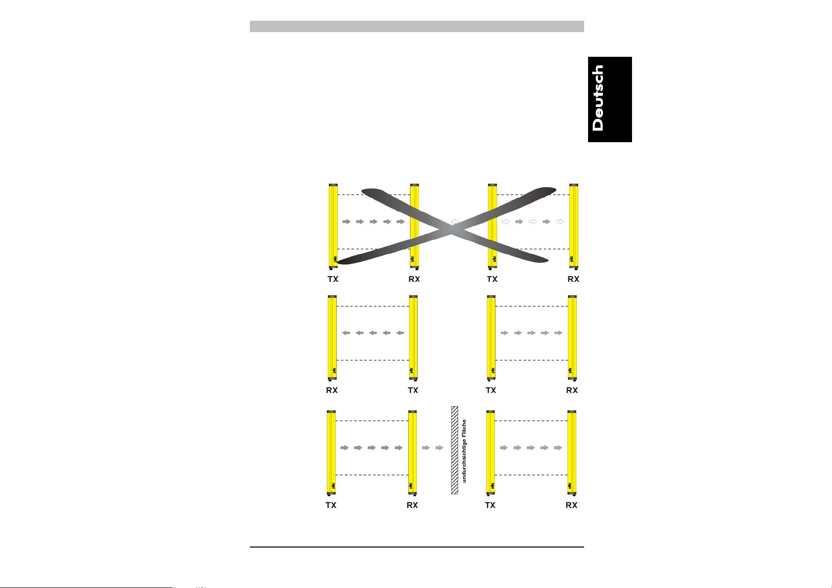
2.2.3. Installation von mehreren Sicherheitslichtgittern nebeneinander
Ist die Installation von mehreren Schutzeinrichtungen in
nebeneinander liegenden Bereichen erforderlich, ist darauf zu achten,
dass der Sender einer Einrichtung nicht den Empfänger einer anderen
Einrichtung störend beeinflußt. Um dies zu verhindern, müssen die
Geräte entgegengesetzt, oder durch eine Abschirmung
(undurchsichtige Fläche) getrennt, montiert werden.
Abb.10 zeigt das Beispiel einer störungsgefährdeten Installation und
zweier richtiger Installationen.
NEIN
J
Abb. 10
14
Page 18
Bedienungsanleitung PSEN op2H Serie
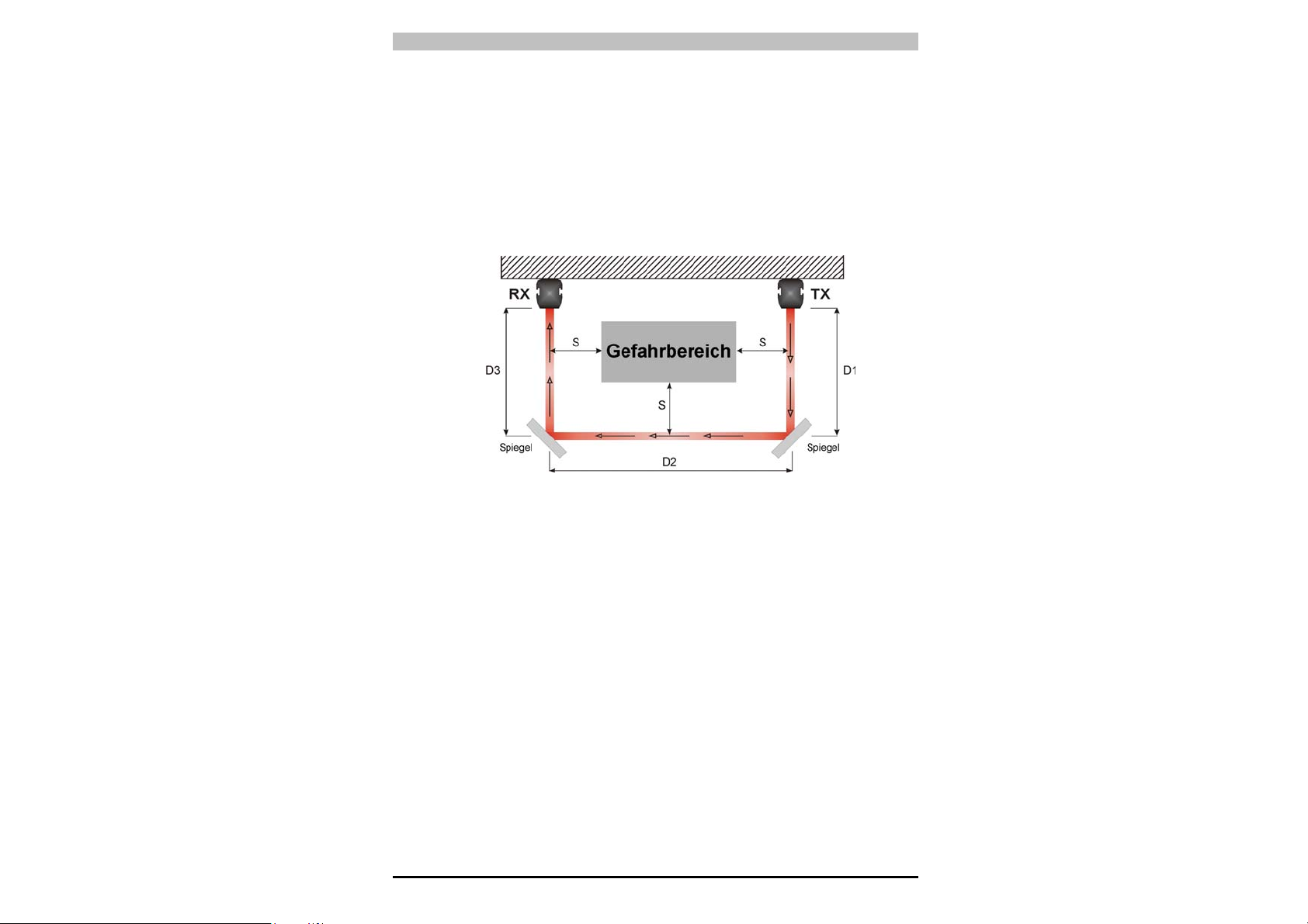
2.2.4. Einsatz von Strahlumlenkspiegeln
Mit Hilfe von Strahlumlenkspiegeln lassen sich Gefahrbereiche mit
mehreren Zugangsseiten überwachen.
Abb.11 veranschaulicht eine mögliche Lösung zur Überwachung von
drei verschiedenen Zugangsseiten unter Einsatz von zwei in einem
Neigungswinkel von 45° zum Lichtgitter angebrachten
Strahlumlenkspiegeln.
Abb. 11
Bei der Verwendung von Umlenkspiegeln ist folgendes zu beachten:
• Bei der Verwendung von Umlenkspiegeln ist die Ausrichtung von
Sende- und Empfangseinheit besonders kritisch; bereits eine
minimale seitliche Verschiebung des Spiegels genügt, um die
Ausrichtung aufzuheben.
• Der Mindestsicherheitsabstand (S) ist für alle Zugangsseiten
einzuhalten.
• Beim Einsatz eines Umlenkspiegels reduziert sich die effektive
Reichweite um ca. 15%. Die Verwendung von zwei oder mehr
Umlenkspiegeln hat eine weitere Reduzierung der Reichweite zur
Folge (mehr Details s. technische Spezifikationen der verwendeten
Spiegel).
• Verwenden Sie nie mehr als drei Spiegel pro Einrichtung.
• Durch eventuellen Staub oder Schmutz auf der reflektierenden
Spiegeloberfläche wird die Reichweite drastisch reduziert.
15
Page 19

PSEN op2H Serie Bedienungsanleitung
3. MECHANISCHE MONTAGE
Die Sende- (TX) und Empfangseinheit (RX) sind so zu montieren, dass
die jeweiligen Optikflächen parallel aufeinander ausgerichtet und die
Anschlussstecker auf der gleichen Seite angeordnet sind. Der Abstand
zwischen Sender und Empfänger muss innerhalb der eingesetzten
Modell-Reichweite sein (siehe Typenschild bzw. Kap.9 "Technische
Daten").
Nehmen Sie die Feinausrichtung entsprechend den Hinweisen in
Kap.5 "Ausrichtung" vor.
Verwenden Sie für die Befestigung die mitgelieferten Winkel wie in
Abb. 12 ersichtlich.
16
Page 20
Bedienungsanleitung PSEN op2H Serie
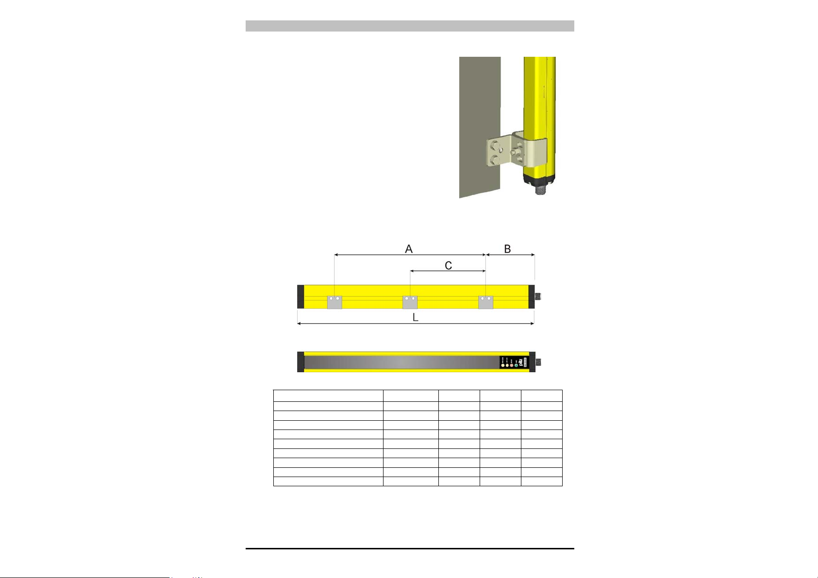
Für Installationen, bei welchen beim
Ausrichten keine größeren mechanischen
Korrekturen notwendig sind, sind auf
Wunsch spezielle L-Halterungen (siehe
Abb. 13) lieferbar.
Verstellbare Halterungen ermöglichen die
Neigung der Einheiten um ± 5° und sind
ebenfalls auf Wunsch lieferbar.
Bei Anwendungen mit besonders starken
Vibrationen empfehlen wir den Einsatz von
Befestigungswinkeln mit
Schwingungsdämpfern. Die Zeichnung
und die Tabelle geben die empfohlenen
Befestigungspunkte in Abhängigkeit von
der Länge des Lichtgitters an.
Abb. 13
PSEN op2H-30-015
PSEN op2H-30-030 359 179 90 -
PSEN op2H-30-045 506 286 110 -
PSEN op2H-30-060 653 373 140 -
PSEN op2H-30-075 800 460 170 -
PSEN op2H-30-090 947 547 200 -
PSEN op2H-30-105 1094 654 220 -
PSEN op2H-30-120 1241 841 200 420
PSEN op2H-30-135 1388 988 200 494
PSEN op2H-30-150 1535 1095 220 547
MODELLE L (mm) A (mm) B (mm) C (mm)
212 72 70 -
17
Page 21
PSEN op2H Serie Bedienungsanleitung
2
3
4
5
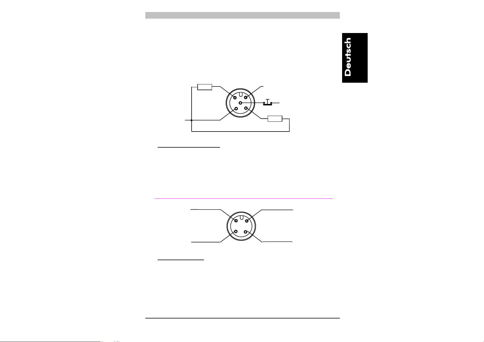
4. ELEKTRISCHE ANSCHLÜSSE
Sämtliche elektrische Anschlüsse der Sende- und Empfangseinheit
erfolgen je über einen M12-Stecker, der an der Unterseite der beiden
Einheiten angeordnet ist. Der Empfänger wird über ein 5-poliges Kabel
und der Sender über ein 4-poliges Kabel angeschlossen.
0V
OSSD1 PNP
+24Vdc
12
5
3
4
+24Vdc
OSSD2 PNP
EMPFÄNGER (RX):
1 = braun = +24 Vdc
= weiß = OSSD 1
= blau = 0 V
= schwarz = OSSD 2
= grau = TEST (s. Hinweis)*
* = automatischer START TEST/RESET-Funktion
nicht belegt
+24Vdc
2
1
0V
3
nicht belegt
4
SENDER (TX):
1 = braun = +24 Vdc
3 = blau = 0 V
18
Page 22
Bedienungsanleitung PSEN op2H Serie
4.1. Bemerkungen zu den Anschlüssen
Um den korrekten Betrieb der PSEN op2H-Schutzeinrichtung zu
gewährleisten beachten Sie bitte folgende Hinweise:
• Die Anschlusskabel dürfen keinesfalls mit Kabeln in Kontakt
kommen oder in deren Nähe verlegt werden (z.B.: Einspeisung von
Motoren, Inverter usw.), die starke elektromagnetische Störfelder
erzeugen und deshalb die Funktionstüchtigkeit der Einrichtung
gefährden können.
• Die Verwendung von mehradrigen Kabeln zum Anschluss der
Ausgänge von mehr als einem Sicherheitsgitter ist nicht zulässig.
• Die TEST-Leitung ist über eine Taste mit Öffnerkontakt an die
Spannungsversorgung des Empfängers (RX) der ESPE
anzuschließen. Sie sollten den Test manuell (durch Drücken der
Taste) mindestens einmal täglich zur Kontrolle des sachgerechten
Betriebs der Schutzeinrichtung vornehmen.
• Sofern die TEST-Leitung beim Einschalten der ESPE an 0 VDC
angeschlossen ist, schaltet das Sicherheitsgitter in den Schutzmodus (BREAK-Bedingung) (siehe Kap. 7 „Diagnosefunktionen“).
• Die TEST-Taste muss so angebracht sein, dass die Bedienperson
freie Sicht auf den Schutzbereich hat, wenn sie Test- Eingriffe
vornimmt (siehe Kap. 6 „START-Modus“).
• Bei Schutzklasse 3 ist die Erdung von Sende- und Empfangseinheit
nicht erlaubt, jedoch die Verwendung von SELV/PELV Netzteilen
erforderlich.
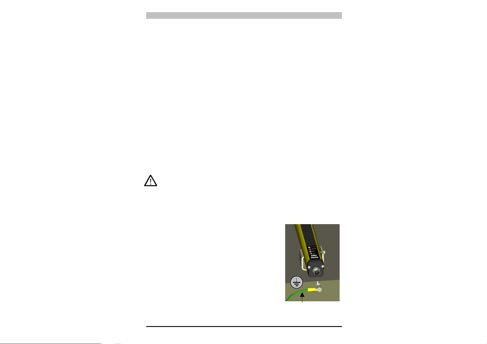
• Falls Auswertegeräte oder eine
Spannungsversorgung ohne sichere
Trennung angeschlossen werden, muss
das Lichtgitter in der Schutzklasse 1
betrieben werden. Hierzu müssen Sendeund Empfangseinheit mit dem
Schutzerde-Symbol gekennzeichnet und
einer Spezialschraube geerdet werden.
Beides ist im Lieferumfang enthalten.
Die Spezialschraube ersetzt eine der
Deckelschrauben.
19
Page 23
PSEN op2H Serie Bedienungsanleitung
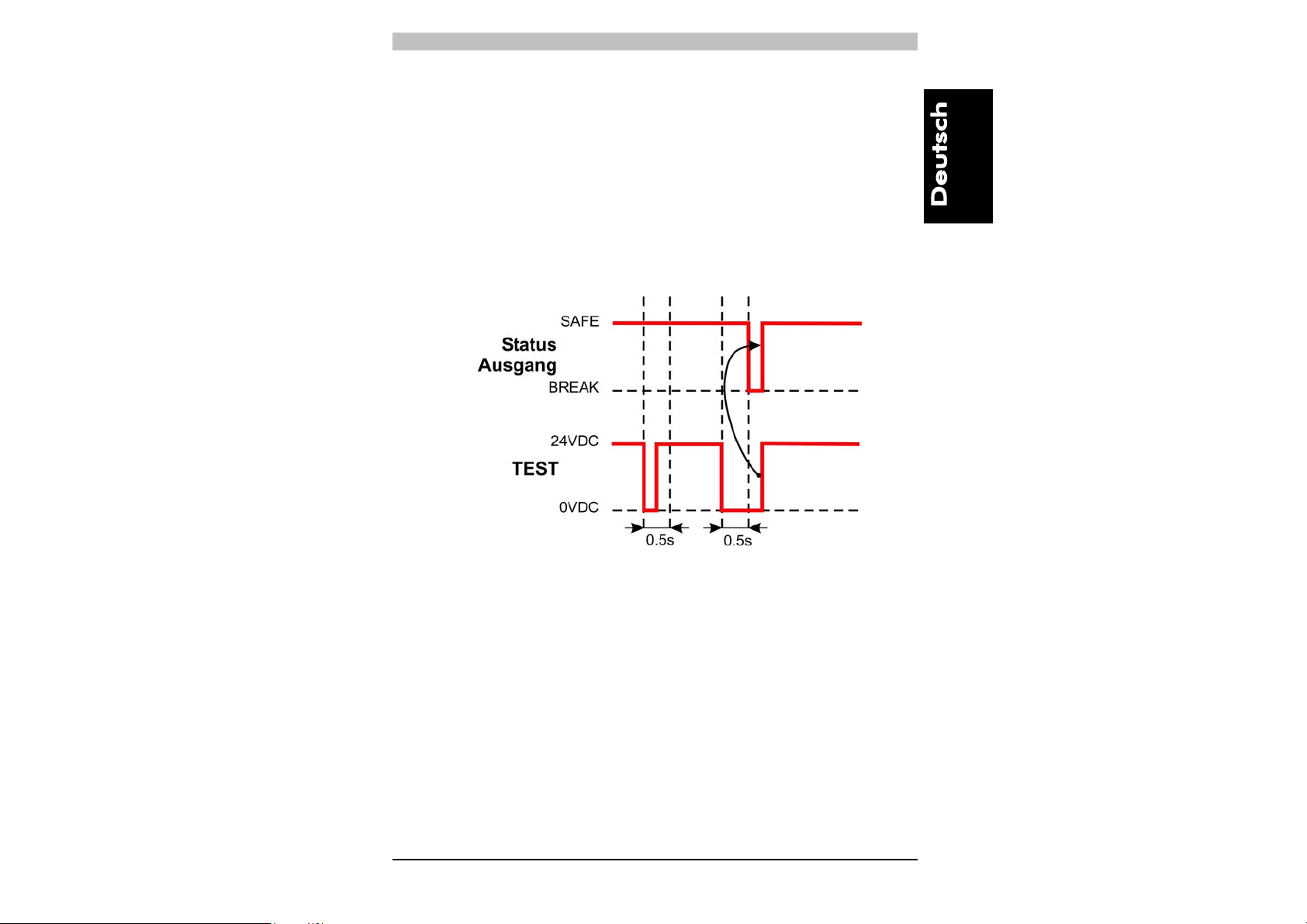
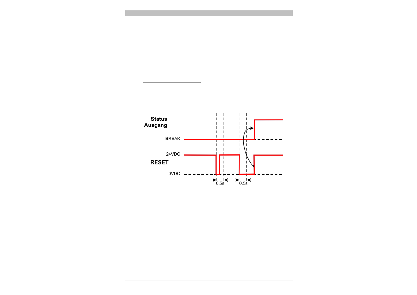
4.2. Zeitdiagramm der TEST-Funktion
Während des normalen Betriebzyklus’ wird automatisch alle 0,5 s die
Funktionalität der Ausgänge des Lichtgitters selbstständig überprüft.
Die TEST-Funktion kann zudem auch durch Drücken der Taste
aktiviert werden; bei der TEST-Aktivierung sollte die Taste mindestens
0,5 Sekunden lang gedrückt bleiben, wie im untenstehenden
Zeitdiagramm ersichtlich.
AUTOMATISCHE VERSION
20
Page 24
Bedienungsanleitung PSEN op2H Serie
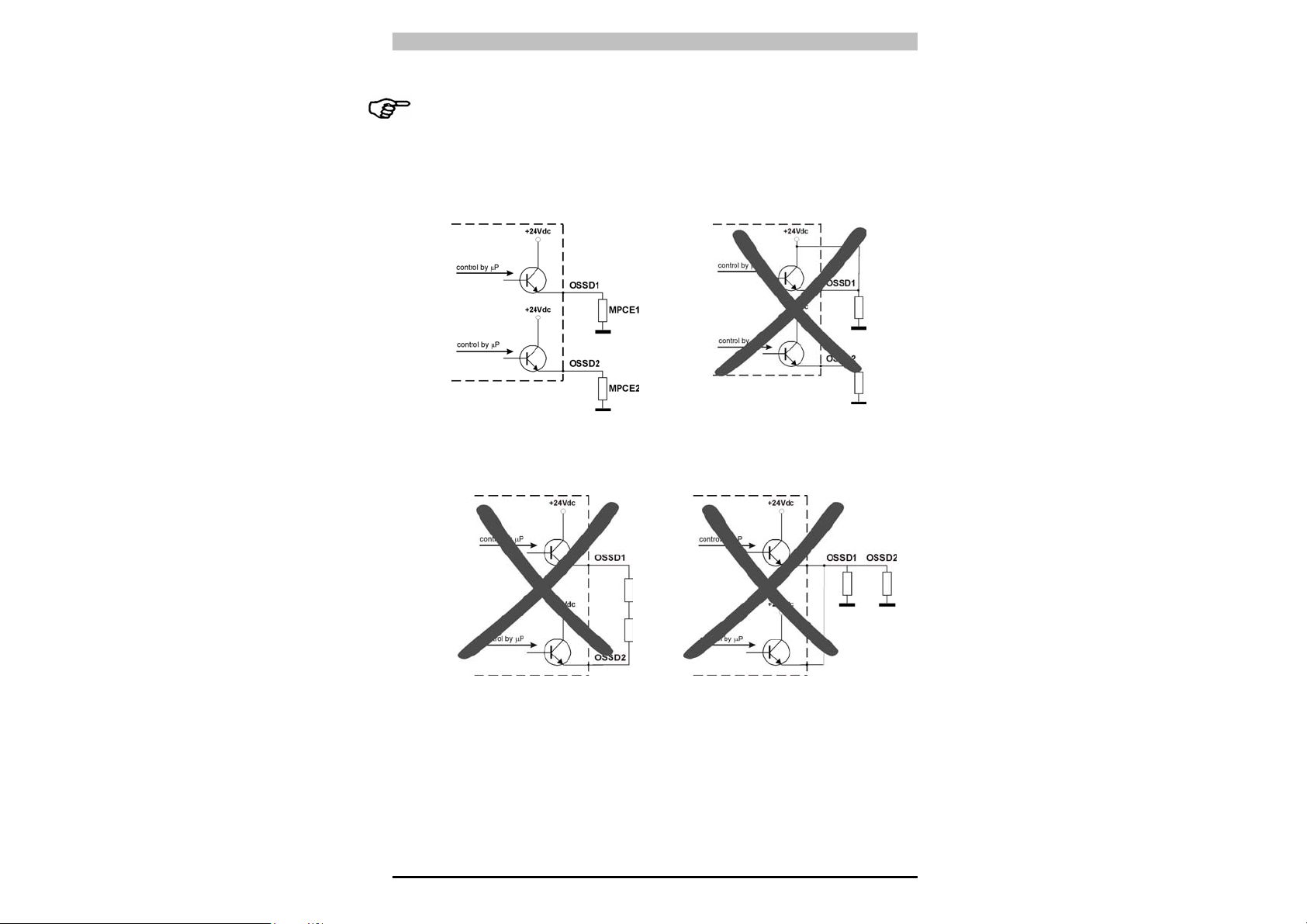
• Die Sicherheitsausgänge OSSD1 und OSSD2 dürfen in keinem Fall
in Reihe oder parallel geschaltet werden (Abb. 15, 16, 17), sondern
sind beide einzeln wie in Abb.14 gezeigt zu verwenden. Sollte
irrtümlicherweise eine dieser beiden Konfigurationen verwendet
werden, führt dies zu einer Betriebsstörung (s. Kap.7
"Diagnosefunktionen").
Abb. 14
Abb. 15
Abb. 16
Abb. 17
21
Page 25
PSEN op2H Serie Bedienungsanleitung
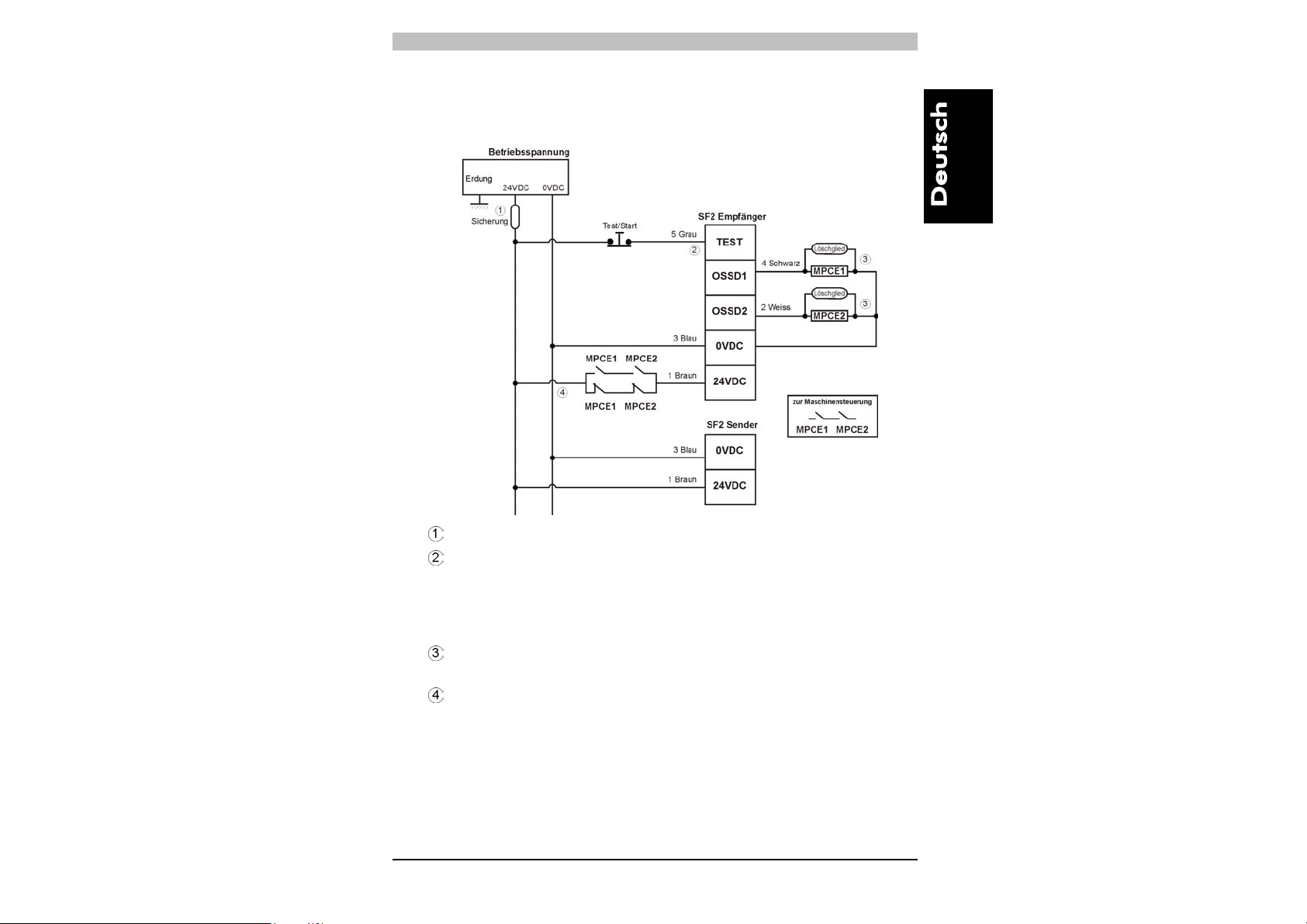
Im folgenden Schema sind die Anschlussmöglichkeiten für ein PSEN
op2H Sicherheitsgitter mit zwangsgeführten Relais’ (MPCE)
dargestellt.
Sicherung; vom Anwender bereitzustellen
Im Normalbetrieb muss die TEST-Leitung über eine Taste mit
Öffnerkontakt an +24 Vdc angeschlossen sein. Sollte diese
Leitung nicht angeschlossen oder an 0 Vdc angeschlossen
sein, schaltet das Sicherheitsgitter in den Schutzmodus
(BREAK).
Die Relaisspulen müssen mit entsprechenden
Funkenlöschgliedern versehen sein.
Wenn das Schutzfeld unterbrochen wird und einer der
Kontakte geschlossen bleibt (Verschweißung der Kontakte),
wird die Versorgungsspannung mit oben gezeigter Beschaltung
unterbrochen und der zweite Kontakt schaltet die Maschine ab.
22
Page 26
Bedienungsanleitung PSEN op2H Serie
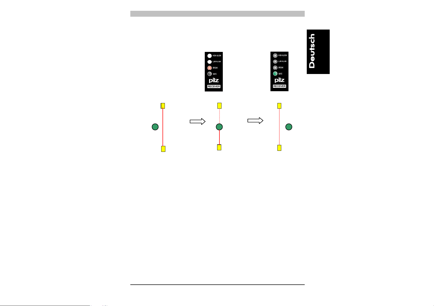
5. AUSRICHTUNG
Die Ausrichtung der Sende- und der Empfangseinheit ist für eine
einwandfreie Funktionsweise der Einrichtung unerlässlich.
Eine perfekte Ausrichtung ist erreicht, wenn die optischen Achsen des
ersten und letzten Strahls des Senders mit den optischen Achsen der
entsprechenden Elemente des Empfängers zusammentreffen.
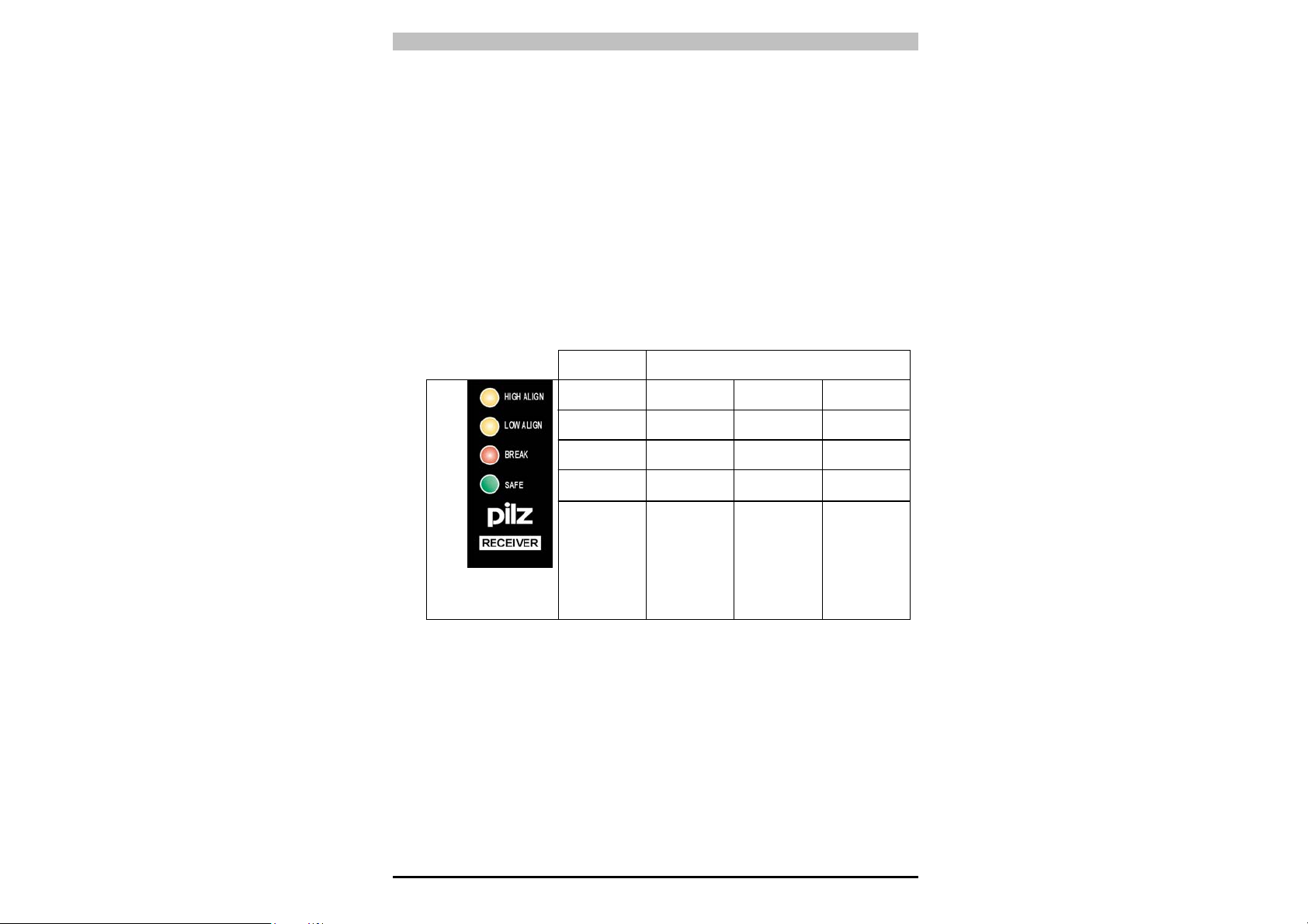
Zwei gelbe LEDs "HIGH ALIGN", "LOW ALIGN" an der SF2Empfangseinheit erleichtern die Ausrichtung. Im Normalbetrieb zeigen
die LEDs den Funktionsstatus des Sicherheitsgitters wie nachfolgend
dargestellt an.
5.1. Anleitungen für eine sachgerechte Ausrichtung (Automatischer START)
Gelb
Gelb
Rot
Grun
Nachdem die mechanische Montage und die elektrischen Anschlüsse
wie in den vorstehenden Abschnitten beschrieben vorgenommen
wurden, kann das Lichtgitter wie nachfolgend beschrieben
ausgerichtet werden:
FUNKTIONSSTATUS
SAFE
status
OFF
OFF
OFF
ON
- Normalbetrieb
- Keine Strahlen
unterbrochen
ON
ON
ON
OFF
- Einheiten nicht
ausgerichet
- Oberseite
nicht ausgerichet
- Oberster
Strahl unterbrochen
BREAK
status
OFF
ON
ON
OFF
- Unterseite
nicht ausgerichtet
- Unterster
Strahl
unterbrochen
OFF
OFF
ON
OFF
- Einheiten
ausgerichtet,
aber
mindestens
ein Strahl
(außer dem
obersten u.
untersten) ist
unterbrochen
• Vergewissern Sie sich, dass am Sender (TX) die grüne LED
"POWER ON" und die gelbe LED "SAFE" leuchten. Der
sachgerechte Betrieb des Senders wird damit bestätigt.
• Überprüfen Sie, ob der Schutzbereich des Lichtgitters frei ist.
23
Page 27

PSEN op2H Serie Bedienungsanleitung
• Stellen Sie sicher, dass sich der Empfänger (RX) in einem der
nachstehenden Zustände befindet:
• BREAK Status: grüne LED "SAFE" leuchtet nicht und rote LED
"BREAK" leuchtet. Die Anzeige der beiden gelben LEDs
„HIGH ALIGN“ und „LOW ALIGN“ ist unerheblich.
-> die Einheiten sind nicht ausgerichtet.
• SAFE Status: grüne LED "SAFE" leuchtet und rote LED
"BREAK" leuchtet nicht. Die beiden gelben LEDs "HIGH
ALIGN" und "LOW ALIGN" leuchten nicht.
-> die Einheiten sind ausgerichtet.
• Zum Ausrichten der Einheiten gehen Sie wie folgt vor:
A Halten Sie den Empfänger fest und richten Sie den Sender so
aus, dass die obere gelbe LED "HIGH ALIGN" erlischt und die
erfolgte Ausrichtung des ersten oberen Strahls bestätigt.
B Drehen Sie den Sender, bis auch die untere gelbe LED "LOW
ALIGN“ erlischt.
HINWEIS
: Stellen Sie sicher, dass die grüne LED SAFE
permanent leuchtet.
C Umgrenzen Sie mit geringfügigen Anpassungen zuerst der
einen und dann der anderen Einheit den Bereich, in dem die
LED "SAFE" permanent grün leuchtet. Plazieren Sie die
beiden Einheiten in der Mitte dieses Bereichs.
• Befestigen Sie die beiden Einheiten stabil mit Hilfe der Winkel
• Stellen Sie sicher, dass die grüne LED des Empfängers leuchtet
(freie Lichtstrahlen, Betriebszustand "SAFE") und dass diese bei
Unterbrechung von auch nur einem einzigen Strahl auf rot
umschaltet (erfasstes Objekt, Betriebszustand "BREAK").
• Führen Sie diesen Test mit einem dafür vorgesehenen
zylindrischen "Teststab" durch, dessen Durchmesser der Auflösung
des Geräts entspricht (30mm).
HINWEIS:
Wenn Sie den Teststab von oben nach unten längs des
gesamten Abtastbereichs mit beliebigem Abstand von
beiden Einheiten führen, muss die LED "BREAK" ohne
Störungen permanent rot aufleuchten.
Wir empfehlen Ihnen, diesen Test täglich zu wiederholen.
24
Page 28
Bedienungsanleitung PSEN op2H Serie
6. START-MODUS
Wenn die Strahlen zwischen Sender und Empfänger mit einem
undurchsichtigen Objekt unterbrochen werden, schalten die OSSD
Ausgänge und die Sicherheitskontakte öffnen (Betriebszustand
"BREAK").
Der Wiederanlauf zum normalen ESPE-Betrieb (Sicherheitskontakte
schließen, Betriebszustand "SAFE") erfolgt mit automatischem Start:
• Automatischer START:
nimmt die ESPE ihren normalen Betrieb wieder auf, sobald das
erfasste Objekt aus dem Schutzfeld entfernt worden ist.
ZEITDIAGRAMM DER RESET-FUNKTION
nach einer Schutzfeldunterbrechung
25
Page 29
PSEN op2H Serie Bedienungsanleitung
In Abb. 18 sind die beiden Betriebsarten schematisch dargestellt.
SAFE
X
X
ON
OFF
BREAK
Automatischer
START
Normalbetrieb
Strahlen frei
RX RX RX
TX
Strahlen
unterbrochen
OSSD OFF OSSD ON
TX
Strahlen frei
TX
Abb. 18
X = bei diesem Modus ist es unerheblich, ob diese LEDs an oder aus sind.
OFF
OFF
OFF
ON
26
Page 30
Bedienungsanleitung PSEN op2H Serie
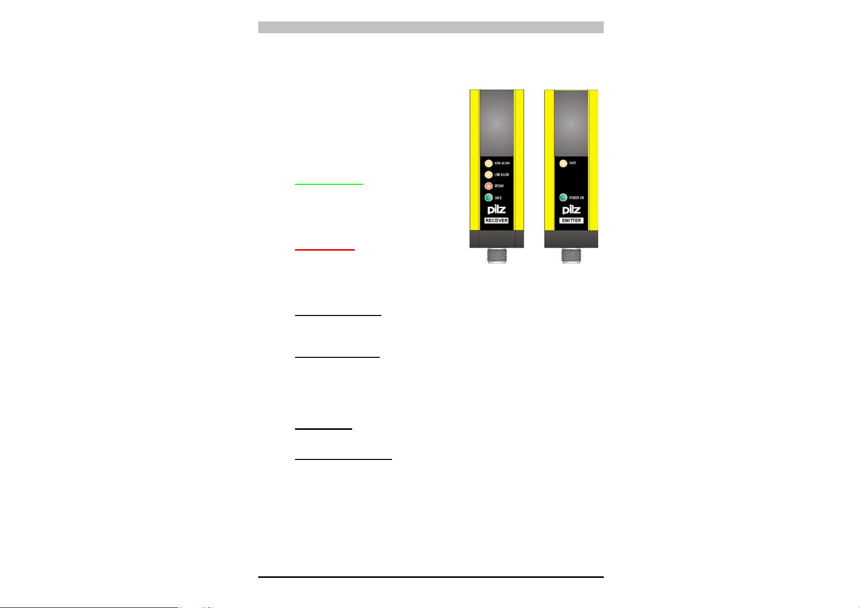
7. DIAGNOSEFUNKTION
7.1. Funktionsanzeigen
4 LEDs am Empfänger und 2 LEDs am
Sender informieren den Anwender über
den Betriebszustand der PSEN op2HSchutzeinrichtung. (Abb. 19).
• LED SAFE/BREAK:
• GRÜNE LED SAFE leuchtend
zeigt an, dass Sender und
Empfänger aufeinander ausgerichtet
und das Schutzfeld frei ist. Die
Ausgänge sind ON.
• ROTE LED BREAK leuchtend
zeigt an, dass Sender und
Empfänger nicht aufeinander
ausgerichtet sind oder das Schutzfeld durch ein Objekt
unterbrochen ist. Die Ausgänge sind OFF.
• LED HIGH ALIGN: (gelb) aus zeigt die optimale Ausrichtung der
letzten Sender-Optik mit der entsprechenden Empfänger-Optik an
(oberster Lichtstrahl des Geräts).
• LED LOW ALIGN: (gelb) aus zeigt die optimale Ausrichtung der
ersten Sender-Optik mit der entsprechenden Empfänger-Optik an
(unterster Lichtstrahl des Geräts).
Die LEDs an der Sendeeinheit (TX) haben folgende Bedeutung.
• LED SAFE (gelb): leuchtend zeigt an, dass die Einheit
vorschriftsmäßig sendet.
• LED POWER ON (grün): leuchtend zeigt die korrekte
Stromversorgung der Einheit an.
27
Page 31

PSEN op2H Serie Bedienungsanleitung
7.2. Fehlermeldungen und Diagnose
Über die LEDs, die auch zur Anzeige der Funktionen dienen, kann das
Bedienpersonal die Hauptursachen für einen Geräteausfall oder
-schaden erkennen.
EMPFANGSEINHEIT:
Störung Überprüfung und Behebung
Die Ausgangsanschlüsse überprüfen.
- Falls eine kapazitative Last > 0.1µF angelegt wird, den
Kundendienst von PILZ kontaktieren.
- Die TEST-Taste mindestens 0,5 s lang drücken (siehe Kap. 6
“Zeitdiagramm der RESET-Funktion”).
Wenn die Störung weiterhin besteht, den Kundendienst von
PILZ kontaktieren.
- Die TEST-Taste mindestens 0,5 s lang drücken (siehe Kap. 6
“Zeitdiagramm der RESET-Funktion”).
Wenn die Störung weiterhin besteht, den Kundendienst von
PILZ kontaktieren.
- Die Ausrichtung der beiden Einheiten überprüfen
- Die TEST-Taste mindestens 0,5 s drücken (siehe Kap. 6
“Zeitdiagramm der RESET-Funktion”).
Wenn die Störung weiterhin besteht, den Kundendienst von
PILZ kontaktieren.
- Die Einheit aus- und wieder einschalten; dabei sicherstellen,
dass die TEST-Leitung über eine Taste mit Öffnerkontakt an
die Versorgungsspannung angeschlossen ist.
- Spannungsausfall. Anschlüsse und korrekten Wert der
Versorgungsspannung überprüfen.
Sendeeinheit:
Störung Überprüfung und Behebung
- Der Sender funktioniert nicht. Anschlüsse und korrekten Wert
der Versorgungsspannung überprüfen.
- Wenn die Störung weiterhin besteht, den Kundendienst von
PILZ kontaktieren.
- Spannungsausfall. Anschlüsse und korrekten Wert der
Versorgungsspannung überprüfen.
28
Page 32

Bedienungsanleitung PSEN op2H Serie
8. REGELMÄSSIGE KONTROLLEN UND WARTUNG
Folgende regelmäßige Kontrollen müssen von qualifiziertem
Fachpersonal ausgeführt werden.
Stellen Sie sicher, dass:
• Die PSEN op2H-Schutzeinrichtung bei der Prüfung mit dem
Prüfstab in den AUS-Zustand schaltet und während des
Durchfahrens durch das gesamte Schutzfeld auch im BREAKZustand bleibt.
• Die PSEN op2H-Schutzeinrichtung bei der Betätigung der TEST-
Taste in den Aus-Zustand schaltet (rote LED BREAK leuchtet OSSD-Ausgänge öffnen - überwachte Maschine schaltet in den
sicheren Zustand).
• Die Ansprechzeit bei einem Maschine-Stoppt, einschl. Ansprechzeit
der ESPE und Nachlaufzeit der Maschine, sich in den durch die
Berechnung des Sicherheitsabstandes festgelegten Grenzen
befindet (siehe Kap.2 "Installation").
• Der Mindestsicherheitsabstand zwischen der Gefahrenstelle und
dem PSEN op2H -Schutzfeld den Angaben in Kap.2 "Installation"
entspricht.
• Keine Person den Gefahrenbereich zwischen der PSEN op2H-
Schutzeinrichtung und den gefährlichen Maschinenteilen betreten
und dort verweilen kann.
• Der Zugang zum Gefahrenbereich bzw. zur Gefahrenstelle von
keiner ungeschützten Seite möglich ist.
• Die PSEN op2H-Schutzeinrichtung u./o. die externen elektrischen
Anschlüsse keine sichtbaren Beschädigungen aufweisen.
• Die Häufigkeit der Kontrollen hängt von der jeweiligen Anwendung
und von den Bedingungen ab, unter denen das Lichtgitter betrieben
wird.
8.1. Wartung
Die Sicherheitslichtgitter der PSEN op2H Serie benötigen keine
besondere Wartung mit Ausnahme der Reinigung der
Optikabdeckungen. Für die Reinigung sind mit Wasser angefeuchtete
Baumwolltücher zu verwenden.
Es wird empfohlen, weder
- Alkohol, noch Lösungsmittel,
- noch Tücher aus Wolle oder Synthetik zu verwenden.
29
Page 33

PSEN op2H Serie Bedienungsanleitung
8.2. Allgemeine Informationen und nützliche Angaben
Die Sicherheitseinrichtungen sind nur dann von Nutzen, wenn sie
unter Beachtung der Vorschriften korrekt installiert sind.
Sollten Sie feststellen, dass Ihre Kenntnisse für eine korrekte
Installation der Sicherheitseinrichtungen nicht ausreichen, wenden Sie
sich bitte an unseren Technischen Support.
Die Geräte sind durch Schmelzsicherungen gegen Kurzschluß
geschützt. Im Falle eines Kurzschlusses führt dies zu einer
Unterbrechung dieser Sicherungen und beide Einheiten sind an den
technischen Kundendienst von PILZ einzuschicken.
Störungen, die Unterbrechungen der Versorgungsspannung auslösen,
können eine vorübergehende Öffnung der Ausgänge verursachen,
beeinträchtigen jedoch keinesfalls den Sicherheitsbetrieb des
Lichtgitters.
30
Page 34

Bedienungsanleitung PSEN op2H Serie
9. TECHNISCHE DATEN
Versorgungsspannung:
Stromaufnahme Sender (TX): 50 mA max. / 1 W
Stromaufnahme Empfänger (RX): 90 mA max. (ohne Last) / 2.5 W
Ausgänge 2 Ausgänge PNP
Ausgangstrom (für alle Lasten): 500 mA max. (an einzelnem Ausgang)
Ausgangsspannung ON min.: Vdc – 1 V
Ausgangsspannung OFF max.: 0.2 V
Leckstrom: 0.65 mA
Kapazitive Last (rein): 100 nF max
Ohmsche Last (rein):
Ansprechzeit: 24 ms bei maximaler Länge
Sender, Wellenlänge: Infrarot (880 nm)
Auflösung: 30 mm
Reichweite: 0.2…15 m
Sicherheitskategorie: Typ 2
Betriebstemperatur: -0…+ 55 °C
Lagerungstemperatur: -25…+70 °C
Luftfeuchtigkeit: 15…95 % (nicht kondensierend)
Schutzklasse: Klasse 1 / Klasse 3 (**siehe Anmerkung)
Schutzart: IP 65 (EN 60529)
Umgebungshelligkeit: CEI-61496-2
Vibration: Amplitude 0.35 mm, Frequenz 10 ... 55 Hz, 20 Sweeps
Schockbeständigkeit: 16 ms (10 G) 1.000 Schocks für alle Achsen
Bezugsnormen: EN 61496-1; prEN 61496-2
Gehäusematerial: Aluminium lackiert (gelb RAL 1003)
Material obere und untere
Abdeckung:
Linsenmaterial: PMMA
Anschlüsse: 4-poliger M12-Stecker bei TX
Kabellänge: 500 m max. *
Gewicht: 1 kg max/m der Gesamthöhe
Kurzschlussschutz max:1.4 A bei 55°C
min: 1.2 A bei 0°C
* = für den Fall, dass ein längeres Kabel verwendet wird, sind dieselben Spezifikationen
einzuhalten.
** Schutzklasse Klasse 1 Klasse 3
Schutzerdung Pflicht Nicht erlaubt
Symbol für Schutzerdung Pflicht Nicht erlaubt
Schutz durch Niederspannungsnetzteil (SELV und PELV) Empfehlung Pflicht
24 Vdc ± 20% (SELV/PELV)
60Ω min.
(siehe Tabelle „Verfügbare Modelle“)
für alle Achsen; 1Achtel/min., (EN 60068-2-6)
(EN 60068-2-29)
PBT
5-poliger M12-Stecker bei RX
(bei 100 nF kapazitive Last und Vdc = 24 V)
12-Leiter (gemäß EN 50044, EN 60947-5-2)
Pol-Ø = 32 x 0.1mm, Außen-Ø = 5 mm
31
Page 35

PSEN op2H Serie Bedienungsanleitung
10. VERZEICHNIS DER VERFÜGBAREN MODELLE
Modell Länge des
Abstastbereichs
(mm)
PSEN op2H-30-015 147 187 8 14
PSEN op2H-30-030 294 334 16 15
PSEN op2H-30-045 441 481 24 16
PSEN op2H-30-060 588 628 32 17
PSEN op2H-30-075 735 775 40 18
PSEN op2H-30-090 882 922 48 19
PSEN op2H-30-105 1029 1069 56 20
PSEN op2H-30-120 1176 1216 64 22
PSEN op2H-30-135 1323 1363 72 23
PSEN op2H-30-150 1470 1510 80 24
Länge des
Schutz-
bereichs
(mm)
Anz. der
Strahlen
Ansprech-
zeit
(ms)
Auflösung
(mm)
30 0.2…15
Reichweite
(m)
32
Page 36

Bedienungsanleitung PSEN op2H Serie
11. EINBAUABMESSUNGEN
Sämtliche Maße sind in mm angegeben.
MODELL L1 L
PSEN op2H-30-015 227 147
PSEN op2H-30-030 374 294
PSEN op2H-30-045 521 441
PSEN op2H-30-060 668 588
PSEN op2H-30-075 815 735
PSEN op2H-30-090 962 882
PSEN op2H-30-105 1109 1029
PSEN op2H-30-120 1256 1176
PSEN op2H-30-135 1403 1323
PSEN op2H-30-150 1550 1470
2
33
Page 37

PSEN op2H Serie Bedienungsanleitung
12. ZUBEHÖR
Befestigungswinkel
Außerdem erhältlich:
MODELL BESCHREIBUNG
Bracket kit PSEN 4 Montagewinkel (4-teiliges Kit)
Bracket kit PSEN 4 anti vibr. Schwingungsdämpfende Halterungen (4-teiliges Kit)
Bracket kit PSEN 4 adjust. Verstellbare Halterungen (4-teiliges Kit)
34
Page 38

Bedienungsanleitung PSEN op2H Serie
Umlenkspiegel
MODELL BESCHREIBUNG
Mirror 550mm Umlenkspiegel H= 550 mm
Mirror 700mm Umlenkspiegel H= 700 mm
Mirror 900mm Umlenkspiegel H= 900 mm
Mirror 1000mm Umlenkspiegel H= 1000 mm
Mirror 1270mm Umlenkspiegel H= 1270 mm
L1 (mm) L2 (mm)
554 384
704 534
904 734
1004 834
1264 1094
35
Page 39

PSEN op2H Serie Bedienungsanleitung
Bodenhalterungen
MODELL BESCHREIBUNG
Stand 1000mm Bodenhalterungen H= 1000 mm
Stand 1200mm Bodenhalterungen H= 1200 mm
Stand 1500mm Bodenhalterungen H= 1500 mm
Stand 1800mm Bodenhalterungen H= 1800 mm
L (mm) X (mm)
1000 30x30
1200 30x30
1500 45x45
1800 45x45
36
Page 40

Page 41

PSEN op2H Series Operating Manual
OVERVIEW OF CONTENTS
1. GENERAL INFORMATION .......................................................................................... 1
1.1. General description of the safety devices ........................................................... 1
1.2. How to select a safety device.............................................................................. 3
1.3. Typical application areas..................................................................................... 5
1.4. Safety information ............................................................................................... 6
2 INSTALLATION............................................................................................................ 7
2.1. Precautionary measures when selecting and installing the device ..................... 7
2.2. General information on positioning the device .................................................... 8
2.2.1. Minimum safety distance ...................................................................... 10
2.2.2. Minimum distance from reflective surfaces .......................................... 12
2.2.3. Installing several adjacent safety light curtains .................................... 14
2.2.4. Use of deviating mirrors........................................................................ 15
3. MECHANICAL ASSEMBLY....................................................................................... 16
4. ELECTRICAL CONNECTIONS ................................................................................. 18
4.1. Notes on connections........................................................................................ 19
4.2. Timing diagram for the TEST function .............................................................. 20
5. ALIGNMENT............................................................................................................... 23
5.1. Correct alignment procedure (Automatic START) ............................................ 23
6. START MODE ............................................................................................................ 25
7. DIAGNOSTIC FUNCTION.......................................................................................... 27
7.1. Function indicators ............................................................................................ 27
7.2. Error messages and diagnostics....................................................................... 28
8. REGULAR CHECKS AND MAINTENANCE ............................................................. 29
8.1. Maintenance...................................................................................................... 29
8.2. General information and useful data ................................................................. 30
9. TECHNICAL DETAILS............................................................................................... 31
10. LIST OF AVAILABLE MODELS ................................................................................ 32
11. OVERALL DIMENSIONS........................................................................................... 33
12. ACCESSORIES.......................................................................................................... 34
Page 42

Operating Manual PSEN op2H Series
1. GENERAL INFORMATION
1.1. General description of the safety devices
Safety light curtains from the PSEN op2H series are optoelectronic
safety devices. They secure work areas in which operating personnel
can come into contact with moving parts of machinery, robots and
automated systems in general, which present a risk of physical injury.
Safety light curtains in the PSEN op2H series are designed as safe
Type 2 systems for accident prevention in accordance with applicable
international standards, in particular:
EN 61496-1: 1997 Safety of machinery: Electrosensitive
protective equipment. Part 1: General
requirements and tests.
prEN 61496-2: 1997 Safety of machinery - Electrosensitive
protective equipment. Part 2: Particular
requirements for equipment using active
optoelectronic protective devices.
The device, which consists of a
transmitter and a receiver housed
in robust aluminium profiles,
secures the protected area by
generating an infrared protected
field, defined by the height and
width of that protected field.
Both the control and evaluation
logic are located inside the two
units; the electrical connection is
made via M12 connectors, which
are positioned underneath the
profiles. The transmitter and
receiver are synchronised optically,
the two units do not have to be
connected directly to each other.
The infrared beams are controlled
and monitored via a
Fig. 1
microprocessor, which provides the user with information about the
operating status of the light curtain via LED indicators (see Ch. 7,
“Diagnostic functions”).
1
Page 43

PSEN op2H Series Instruction Manual
Two yellow LEDs simplify the alignment of the two units during
installation (see Ch. 5 “Alignment”).
As soon as an object, a limb or the operator’s body interrupts the
beams sent by the transmitter, the signals at both outputs (OSSD)
immediately switch from High to Low and the machine connected to
the corresponding OSSDs is stopped.
NB:
This manual uses the following abbreviations as defined in
the applicable standards:
AOPD Active optoelectronic protective device
ESPE Electrosensitive protective equipment
MPCE Machine primary control element
OSSD Output signal switching device (switching output)
TX Transmitter
RX Receiver
Some sections or paragraphs in this manual contain information of
particular importance to those using or setting up the device.
These sections are highlighted using the following symbols:
Detailed notes and descriptions of specific features on the PSEN op2H
safety devices, designed to explain their operation more clearly.
Specific installation guidelines.
This warning must be heeded! It warns of a hazardous situation that
could lead to serious injury and death and indicates preventive
measures that can be taken.
This manual contains all the information required for the selection and
operation of the PSEN op2H
safety devices.
Specialised knowledge of safety issues is required to integrate a safety
light curtain correctly on power-driven machinery.
As this manual is unable to provide such information in full, please
contact the technical service department at PILZ for any information
about the operation of the PSEN op2H safety light curtains and the
safety regulations relating to correct installation (see Ch. 8 “Regular
checks and maintenance”).
2
Page 44

Operating Manual PSEN op2H Series
1.2. How to select a safety device
Three characteristic features should be taken into account when
selecting a safety light curtain:
• Resolution,
depending on the part of the body requiring protection.
Safety light curtains in the PSEN op2H series have a resolution of
30mm, which is suitable for hand protection.
R = 30mm Hand protection
Typ e 2
The resolution (R) of a device is understood to be the minimum size
an opaque object must be in order to obscure at least one of the
beams that form the sensing area.
As shown in Fig. 2, the resolution depends exclusively on the
geometrical properties of the lenses, the diameter and the centre
distance; it is independent of the ambient and operating conditions
of the light curtain.
The resolution can be calculated using the following formula:
Fig. 2
R = I + d
3
Page 45

PSEN op2H Series Instruction Manual
• Height of the protected area
Here it is important to distinguish between the “Height of the
sensing area” and the “Height of the protected area“ (Fig. 3).
- The height of the sensing area is the distance between the
upper limit of the first lens and the lower limit of the last lens.
- The height of the protected area is the effective protected area,
in which an opaque object whose size is greater than or equal to
the resolution of the light curtain will safely obscure the beam.
Fig. 3
• Safety distance
Great care must be taken when calculating the distance at which
the safety device should be positioned in relation to the hazardous
machinery. (Please see Ch. 2, “Installation”, for details of how to
calculate the safety distance.)
4
Page 46

Operating Manual PSEN op2H Series
1.3. Typical application areas
Safety light curtains from the PSEN op2H series can be used in all
areas of automation where it is necessary to control and guard access
to danger zones.
In particular they are used to stop the hazardous movement of
mechanical parts on:
- Automatic machinery
- Packaging, handling and storage machinery
- Textile processing, woodworking and ceramic processing
machinery
- Automatic or semi-automatic assembly lines
- Automated high-bay racking
With food industry applications, please contact customer services at
PILZ to check whether the light curtain’s housing material can
withstand the chemical substances that may be used in the production
process.
The following illustrations provide an overview of some of the main
application areas:
5
Page 47

PSEN op2H Series Instruction Manual
1.4. Safety information
For the proper, safe use of the safety devices in the PSEN op2H
series, the following guidelines must be followed:
• It must be possible to control the machine stop electrically.
• The control system must be able to stop the hazardous machine
movement immediately at any stage of the operating cycle.
• The light curtain and its respective electrical connections must be
installed by qualified personnel, in line with the guidelines stated in
the relevant chapters (see Ch. 2, 3, 4, 5, 6).
• The light curtain must be positioned in such a way that the danger
zone cannot be accessed without interrupting the beams (see Ch. 2
“Installation”).
• Personnel working in the danger zone must be appropriately
trained with regard to the operation of the safety light curtain.
• The TEST button must be positioned outside the danger zone in
such a way that operating personnel have a complete view of the
danger zone during all test operations.
6
Page 48

Operating Manual PSEN op2H Series
2 INSTALLATION
2.1. Precautionary measures when selecting and installing the device
• Make sure that the category guaranteed by the safety device from
the PSEN op2H series (Type 2) matches the risk assessment for
the machinery that is to be monitored, as defined in the standard
EN 954-1.
• The outputs (OSSD) on the ESPE must be used as machine stop
devices and not as command devices (the machine must have its
own START command).
• The dimensions of the smallest object to be detected must not be
less than the resolution level of the device.
• The environment in which the ESPE is installed must comply with
the technical details stated for the PSEN op2H light curtain series in
Ch. 9.
• Avoid installing the device, particularly the receiver, close to intense
and/or flashing light sources.
• Avoid strong electromagnetic interference as this can adversely
affect the proper operation of the device.
• Smoke, mist or dust within the operating environment can reduce
the range of the safety device by up to 50%.
• Sudden temperature fluctuations beyond freezing point can cause
condensation to form on the surface of the lenses, adversely
affecting the proper operation of the safety device.
7
Page 49

PSEN op2H Series Instruction Manual
2.2. General information on positioning the device
For effective protection it is necessary to proceed very carefully when
positioning the device; in particular, the device must be installed in
such a way that the danger zone cannot be accessed without
interrupting the protected field.
To exclude the possibility of the machine being accessed from above
or below (Fig. 4a), it is necessary to install a light curtain of sufficient
length to completely cover access to the danger zone (Fig. 4b).
NO
Fig. 4a
Fig. 4b
8
Page 50

Operating Manual PSEN op2H Series
Also, under normal operating conditions, it must not be possible to
start the machine until the operator is outside the danger zone.
If it is impossible to install the light curtain in immediate proximity to the
danger zone, a second light curtain must be installed, aligned
horizontally, to exclude access from the side, as shown in Fig. 5b.
Fig. 5a Fig. 5b
If the installation position of the safety device still enables an operator
to access the danger zone without detection, an additional mechanical
barrier must be installed to prevent this happening.
9
Page 51

PSEN op2H Series Instruction Manual
2.2.1. Minimum safety distance
The safety distance of the safety device should be such that the
operator cannot reach the danger zone until the movement of the
hazardous machine part has come to a standstill (see Fig. 6).
According to the standards EN 999, 775 and 294, this distance
depends on four factors:
1 ESPE reaction time (time it takes for the signal at the OSSD
contact to switch from High to Low once the beams have
successfully been interrupted).
2 Machine’s overrun time (time it takes for the machine to come to a
standstill once the ESPE reaction time has elapsed).
3 Resolution of the ESPE.
4 Approach speed of the object requiring detection.
The formula for calculating the safety distance is as follows:
where:
S = Minimum safety distance in mm between the protected field and the
danger zone
K = The speed at which the object requiring detection (body or parts of the
body) approaches the danger zone, in mm/s
t1 = ESPE reaction time in seconds (Ch. 9 “Technical details”).
t2 = Machine’s overrun time in seconds
d = The resolution of the safety device.
C = 8 (d -14) for a safety device with a resolution ≤ 40mm
= 850 mm for a safety device with a resolution > 40 mm
10
Fig. 6
S = K (t1 + t2) + C
Page 52

Operating Manual PSEN op2H Series
Note: The value of K is:
2000 mm/s, if the value calculated for S is ≤ 500 mm
1600 mm/s, if the value calculated for S is > 500 mm
If it is possible to access the danger zone from above and below (Fig.
6) and the devices used have a resolution of >40 mm, the upper beam
must be positioned at a height of ≥900 mm (H2), starting from the
reference plane (e.g. base of the machine), and the lower beam must
be positioned at a height of ≤300 mm (H1).
Where the light curtain must be installed horizontally (Fig.7), the
distance between the danger zone and the most distant optical beam
must equal the value calculated using the following formula:
S = 1600 mm/s (t
+ t2) + 1200 – 0.4 H
1
where:
S = Minimum safety distance in mm between the protected field
and the danger zone
t
= ESPE reaction time in seconds (Ch. 9 “Technical details”).
1
t
= Machine’s overrun time in seconds
2
H = The height of the beams above the floor. This height must
always be less than 1000 mm.
Fig. 7
11
Page 53

PSEN op2H Series Instruction Manual
2.2.2. Minimum distance from reflective surfaces
Reflective surfaces close to the light beams emitted from the safety
device (whether above, below or to the side), may cause passive
reflections and adversely affect detection of the object within the
protected area (Fig. 8).
Fig. 8
Improper installation could mean that a protected field is interrupted
without detection, resulting in serious injury.
12
Page 54

Operating Manual PSEN op2H Series
So, when installing the device close to reflective surfaces (metal walls,
floors, ceilings or workpieces), it is vital that the minimum distance in
relation to reflective surfaces is maintained, as shown in the diagram in
Fig. 9.
This minimum distance depends on:
• The range between the transmitter (TX) and receiver (RX)
• The maximum open angle of the light beams emitted by the
transmitter, in particular:
- 10° for Type 2 ESPE (± 5° to light axis)
The values for the minimum distance in relation to the operating range
can be taken from the illustration in Fig. 9.
800
700
600
500
Type 2
ESPE
400
300
200
100
0
reflecting surface distance (mm)
0
2
4
6
8
10
12
operating distance (m)
14
16
Fig. 9
13
Page 55

PSEN op2H Series Instruction Manual
2.2.3. Installing several adjacent safety light curtains
If it is necessary to install several safety devices in adjacent areas, you
will need to ensure that the transmitter on one device cannot interfere
with the receiver on another.
To prevent this, the devices will need to be installed conversely or
must be separated via screening (opaque surface).
Fig.10 gives an example of an installation that could lead to
interference, plus two correct installations.
NO
YES
YES
Fig. 10
14
Page 56

Operating Manual PSEN op2H Series
2.2.4. Use of deviating mirrors
Deviating mirrors can be used to monitor danger zones where access
is possible from various sides.
Fig. 11 illustrates a potential solution for monitoring three different
access sides using two deviating mirrors positioned at an angle of 45°
to the light curtain.
Fig. 11
Please note the following when using deviating mirrors:
• The alignment of the transmitter and receiver is particularly critical
when you use deviating mirrors; just a slight lateral displacement of
the mirror is enough to lose the alignment.
• The minimum safety distance (S) must be maintained on all access
sides.
• Use of a deviating mirror reduces the effective operating range by
about 15%. If two or more deviating mirrors are used, the range will
be reduced still further (for more details please refer to the technical
specifications for the specific mirror).
• Never use more than three mirrors per device.
• Any dust or dirt on the mirror’s reflective surface will drastically
reduce the operating range.
15
Page 57

PSEN op2H Series Instruction Manual
3. MECHANICAL ASSEMBLY
The transmitter (TX) and receiver (RX) must be assembled so that the
respective optical surfaces are arranged parallel to each other and the
connectors are positioned on the same side. The distance between the
transmitter and receiver must be within the operating range of the
model you are using (see type label or Ch.9, "Technical details").
Align the devices precisely, following the guidelines given in Ch. 5,
"Alignment".
Use the supplied angle bracket to attach the device, as shown in Fig.
12.
16
Page 58

Operating Manual PSEN op2H Series
Special L-brackets are available on request
for installations that require no large
mechanical adjustments during alignment
(see Fig. 13).
Adjustable brackets enable the units to be
inclined by ± 5° and are also available on
request.
Where applications are subject to particularly
strong vibration we recommend the use of
angle brackets with vibration dampers.
The drawing and table below indicate the
recommended fixing points in relation to the
length of the light curtain.
Fig. 13
MODEL L (mm) A (mm) B (mm) C (mm)
PSEN op2H-30-015 212 72 70 -
PSEN op2H-30-030 359 179 90 -
PSEN op2H-30-045 506 286 110 -
PSEN op2H-30-060 653 373 140 -
PSEN op2H-30-075 800 460 170 -
PSEN op2H-30-090 947 547 200 -
PSEN op2H-30-105 1094 654 220 -
PSEN op2H-30-120 1241 841 200 420
PSEN op2H-30-135 1388 988 200 494
PSEN op2H-30-150 1535 1095 220 547
17
Page 59

PSEN op2H Series Instruction Manual
2
3
4
5
4. ELECTRICAL CONNECTIONS
All electrical connections to the transmitter and receiver are made via
an M12 connector, located on the bottom of both the units. The
receiver uses 5-core cable and the transmitter 4-core cable.
OSSD1 PNP
+24Vdc
12
0V
5
3
4
+24Vdc
OSSD2 PNP
RECEIVER (RX):
1 = brown = +24 Vdc
= white = OSSD 1
= blue = 0 V
= black = OSSD 2
= gray = TEST (see note)*
* = Automatic START TEST/RESET function
not assigned
2
+24Vdc
1
0V
3
not assigned
4
TRANSMITTER (TX):
1 = brown = +24 Vdc
3 = blue = 0 V
18
Page 60

Operating Manual PSEN op2H Series
4.1. Notes on connections
To ensure the correct operation of the PSEN op2H safety device,
please note the following:
• Under no circumstances should the connection cables come into
contact with or be laid in proximity to cables that generate strong
electromagnetic interference (e.g.: motor feeds, inverters etc.);
these could compromise the device’s ability to function.
• Multicore cables may not be used to connect the outputs of more
than one light curtain.
• The TEST input should be connected to the supply voltage of the
receiver (RX) on the ESPE via a button with a N/C contact. The test
should be performed manually (by pressing the button) at least
once a day in order to check the proper operation of the safety
device.
• If the TEST input is connected to 0 VDC when the ESPE is
switched on, the safety curtain will switch to guard mode (BREAK
condition) (see Ch. 7 “Diagnostic function”).
• The TEST button must be positioned in such a way that the
operator has a clear view of the protected area when test
procedures are in progress (see Ch. 6 “START mode”).
• With protection class 3, earthing of the transmitter and receiver is
not permitted; SELV/PELV power supplies must be used.
• If evaluation devices or a supply voltage
are connected without safe separation,
the light barrier must be operated in
protection class 1. In this case, the
transmitter and receiver must be labelled
with the protective earth symbol and must
be earthed using a special screw.
Both are supplied with the unit.
The special screw replaces one of the
cover screws.
19
connect to
earth reference
Page 61

PSEN op2H Series Instruction Manual
4.2. Timing diagram for the TEST function
The functionality of the light curtain outputs is automatically tested
every 0.5 s during the normal operating cycle.
The TEST function can also be activated by pressing the button; when
activating the TEST, the button must be held down for at least 0.5
seconds, as illustrated in the timing diagram below.
AUTOMATIC VERSION
20
Page 62

Operating Manual PSEN op2H Series
• Under no circumstances should safety outputs OSSD1 and OSSD2
be wired in series or in parallel (Fig. 15, 16, 17); both must be used
separately, as shown in Fig. 14. Should one of these two
configurations be used in error, a malfunction will occur (see Ch. 7,
"Diagnostic function").
Fig. 14
Fig. 15
Fig. 16
Fig. 17
21
Page 63

PSEN op2H Series Instruction Manual
The following diagram shows the connection options for a PSEN op2H
safety light curtain with positive-guided relays (MPCE).
Fuse; not provided
In normal mode, the TEST input must be connected to +24 Vdc
via a button with a N/C contact. If this line is not connected or is
connected to 0 Vdc, the safety light curtain will switch to guard
mode (BREAK).
The relay coil must be fitted with appropriate suppression
elements.
If the protected field is interrupted and one of the contacts
remains closed (contact welding), the supply voltage with the
wiring shown above is interrupted and the second contact
shuts the machine down.
22
Page 64

Operating Manual PSEN op2H Series
w
w
5. ALIGNMENT
The transmitter and receiver must be aligned to ensure the proper
function of the device.
Perfect alignment is achieved when the optical axes of the
first and last beam from the transmitter meet the optical axes of the
corresponding elements on the receiver.
Two yellow LEDs on the SF2 receiver, "HIGH ALIGN" and "LOW
ALIGN", simplify the alignment process. In normal mode the LEDs
indicate the function status of the safety light curtain, as shown below.
5.1. Correct alignment procedure (Automatic START)
Yello
Yello
Red
Green
Once the mechanical assembly and the electrical connections have
been completed as described in the previous sections, the light curtain
can be aligned as described below:
FUNCTION STATUS
SAFE
status
OFF
OFF
OFF
ON
- Normal
mode
- No beams
interrupted
ON
ON
ON
OFF
- Units not
aligned
- Top not
aligned
- Upper beam
interrupted
BREAK
status
OFF
ON
ON
OFF
- Bottom not
aligned
- Lower beam
interrupted
OFF
OFF
ON
OFF
- Units aligned,
but at least
one beam
(excl. upper
and lower
beam) is
interrupted
• On the transmitter (TX), ensure that the green LED "POWER ON"
and the yellow LED "SAFE" are lit. This confirms that the
transmitter is operating correctly.
• Check that the light curtain’s protected area is clear.
23
Page 65

PSEN op2H Series Instruction Manual
• Make sure that the status of the receiver (RX) is one of the
following:
• BREAK Status: Green LED "SAFE" is unlit and red LED "BREAK"
is lit. The display on the two yellow LEDs “HIGH ALIGN” and “LOW
ALIGN” is insignificant.
-> the units are not aligned.
• SAFE Status: Green LED "SAFE" is lit and red LED "BREAK" is
unlit. The two yellow LEDs “HIGH ALIGN” and “LOW ALIGN” are
both unlit.
-> the units are aligned.
• Follow the steps below to align the units:
A Hold the receiver steady and align the transmitter so that the
upper yellow LED “HIGH ALIGN” goes out, confirming that the
first upper beam has been aligned.
B Rotate the transmitter until the lower yellow LED “LOW ALIGN”
also goes out.
: Make sure that the green LED SAFE is permanently lit.
NOTE
C With a few small adjustments, define the area in which the
LED "SAFE" permanently lights up green; do this first with one
unit and then with the other. Place both units in the centre of
this area.
• Use the angle bracket to firmly secure both the units.
• Make sure that the green LED on the receiver is lit (light beams are
clear, “SAFE” operating status) and that this switches to red if just a
single beam is interrupted (detected object, “BREAK” operating
status).
• Perform this test using a cylindrical “test rod” intended for this
purpose; its diameter should correspond to the resolution of the
device (30mm).
NOTE:
We recommend that you perform this test daily.
24
If you pass the test rod from top to bottom along the
length of the whole sensing area, at any distance from
either unit, the LED “BREAK” must be permanently lit
red, without interruption.
Page 66

Operating Manual PSEN op2H Series
6. START MODE
If the beams between the receiver and transmitter are interrupted by
an opaque object, the OSSD outputs will switch and the safety
contacts will open (“BREAK” operating status).
There are two different ways to restart normal ESPE mode (close
safety contacts, “SAFE” operating status), depending on the device
model:
• Automatic START:
After the protected field has been interrupted,
the ESPE returns to normal mode as soon as the detected object
has been removed from the protected field.
TIMING DIAGRAM FOR THE RESET FUNCTION
25
Page 67

PSEN op2H Series Instruction Manual
Schematics of both operating modes are shown in Fig. 18.
NORMAL
FUNCTIONING
FREE BEAM
RX RX RX
BREAK
X
X
ON
OFF
OSSD OFF OSSD ON
INTERCEPTED
BEAMS
AUTOMATIC
START
VERSION
FREE
BEAMS
SAFE
OFF
OFF
OFF
ON
TX
TX
TX
Fig. 18
X = in this mode, it is insignificant whether these LEDs are on or off.
26
Page 68

Operating Manual PSEN op2H Series
7. DIAGNOSTIC FUNCTION
7.1. Function indicators
4 LEDs on the receiver and 2 LEDs on the
transmitter provide the user with
information about the operating status of
the SAFEasy device. (Fig. 19).
• LED SAFE/BREAK:
• GREEN LED
SAFE is lit; indicates that
the transmitter and receiver are aligned
and the protected field is clear. The
outputs are ON.
• RED LED
BREAK is lit; indicates that
the transmitter and receiver are not
aligned or an object is breaking the
Fig. 19
protected field. The outputs are OFF.
• LED HIGH ALIGN
: (yellow) is unlit; indicates optimum alignment
between the last transmitter optic and the corresponding receiver
optic (top beam on the device).
• ED LOW ALIGN
: (yellow) is unlit; indicates optimum alignment
between the first transmitter optic and the corresponding receiver
optic (bottom beam on the device).
The key to the LEDs on the transmitter (TX) is as follows.
• LED SAFE (yellow): is lit; indicates that the unit is transmitting
correctly.
• LED POWER ON
(green): is lit; indicates that power supply to the
device is correct.
27
Page 69

PSEN op2H Series Instruction Manual
7.2. Error messages and diagnostics
The LEDs that display the function can also be used to show operators
the main causes of a device failure or defect.
RECEIVER:
Fault Checks/remedy
Check the output connections.
- If a capacitive load > 0.1µF is generated, contact PILZ
customer services.
- Hold the TEST button down for at least 0.5 s (see Ch. 6
“Timing diagram for the RESET function”).
If the fault continues, contact PILZ customer services.
- Hold the TEST button down for at least 0.5 s (see Ch. 6
“Timing diagram for the RESET function”).
If the fault continues, contact PILZ customer services.
- Check the alignment of both devices.
- Hold the TEST button down for at least 0.5 s (see Ch. 6
“Timing diagram for the RESET function”).
If the fault continues, contact PILZ customer services.
- Switch the device off and then on again; ensure that the TEST
input is connected to the supply voltage via a button via a N/C
contact.
- Power supply failure. Check the connections, check that the
supply voltage value is correct.
Transmitter:
Fault Checks/ remedy
- Transmitter is not working. Check the connections, check that
the supply voltage value is correct.
- If the fault continues, contact PILZ customer services.
- Power supply failure. Check the connections, check that
the supply voltage value is correct.
28
Page 70

Operating Manual PSEN op2H Series
8. REGULAR CHECKS AND MAINTENANCE
Qualified personnel must carry out the following checks regularly.
Ensure that:
• The SAFEasy device switches to an OFF state when the check with
the test rod is carried out, and remains in the BREAK condition as
the rod is passed across the whole protected field.
• The SAFEasy device switches to an OFF state when the TEST
button is operated (red LED BREAK is lit – signal at the OSSD
outputs switches from High to Low - monitored machine switches to
a safe condition).
• The reaction time at a machine stop, incl. ESPE reaction time and
machine overrun time, is within the limits defined through the
calculation of the safety distance (see Ch. 2 “Installation”).
• The minimum safety distance between the danger zone and the
protected field on the PSEN op2H is in accordance with the details
stated in Ch. 2 “Installation”.
• Nobody can access and remain in the danger zone between the
SAFEasy device and the hazardous machine parts.
• The danger zone cannot be accessed from any unprotected area.
• There is no visible damage to the SAFEasy device and/or the
external electrical connections.
• The interval between such checks depends on the respective
application and on the conditions under which the light curtain is
operated.
8.1. Maintenance
Safety light curtains in the PSEN op2H series require no particular
maintenance, except for cleaning the optical covers
Moist cotton cloths should be used for cleaning.
We recommend that you do not use:
- Alcohol or solvents,
- Cloths made of wool or synthetic material.
29
Page 71

PSEN op2H Series Instruction Manual
8.2. General information and useful data
Safety devices are only beneficial if they are installed correctly, in
accordance with the regulations.
If you find that you do not have the necessary expertise to install the
safety devices correctly, please contact our technical support.
The devices are protected against short circuit through blow-out fuses.
Should a short circuit occur, the system will be interrupted.
The fuses and both devices should be returned to the technical service
department at PILZ.
Faults that result in an interruption to the supply voltage may cause the
outputs to open temporarily, but do not adversely affect the safe
operation of the light curtain.
30
Page 72

Operating Manual PSEN op2H Series
9. TECHNICAL DETAILS
Supply voltage:
Current consumption transmitter
(TX):
Current consumption receiver (RX): 90 mA max. (without load) / 2.5 W
Outputs 2 PNP outputs
Output current (for all loads): 500 mA max. (at a single output)
Output voltage ON min.: Vdc – 1 V
Output voltage OFF max.: 0.2 V
Leakage current: 0.65 mA
Capacitive load (pure): 100 nF max
Resistive load (pure):
Reaction time: 24 ms at maximum length
Transmitter, wavelength: Infra-red (880 nm)
Resolution: 30 mm
Operating range: 0.2…15 m
Category: Type 2
Operating temperature: -0…+ 55 °C
Storage temperature: -25…+70 °C
Humidity: 15…95 % (non-condensing)
Protection class: Class 1 / Class 3 (** see note)
Protection type: IP65 (EN 60529)
Ambient brightness: IEC-61496-2
Vibration: Amplitude 0.35 mm, frequency 10 ... 55 Hz, 20 sweeps
Shock resistance: 16 ms (10 G) 1.000 shocks for all axes
Reference standards: EN 61496-1; prEN 61496-2
Housing material: Varnished aluminium (yellow RAL 1003)
Material of upper and lower cover:
Lens material: PMMA
Connections: 4-pin M12 connector on TX
Cable runs: 500 m max. *
Weight: 1 kg max/m of overall height
Short circuit protection max:1.4 A at 55°C
min: 1.2 A at 0°C
* = The same specifications must be met if a longer cable is used.
** Protection class Class 1 Class 3
Protective earth Mandatory Not permitted
Symbol for protective earth Mandatory Not permitted
Protection through low voltage power supply (SELV
and PELV)
24 Vdc ± 20% (SELV/PELV)
50 mA max. / 1 W
60Ω min.
(See table: “Available models”)
for all axes; 1 octave/min., (EN 60068-2-6)
(EN 60068-2-29)
PBT
5-pin M12 connector on RX
(at 100 nF capacitive load and Vdc = 24 V)
12-core (in accordance with EN 50044, EN 60947-5-2)
Core Ø = 32 x 0.1mm, external Ø = 5 mm
Recommended Mandatory
31
Page 73

PSEN op2H Series Instruction Manual
10. LIST OF AVAILABLE MODELS
Model Length of
sensing area
(mm)
PSEN op2H-30-015 147 187 8 14
PSEN op2H-30-030 294 334 16 15
PSEN op2H-30-045 441 481 24 16
PSEN op2H-30-060 588 628 32 17
PSEN op2H-30-075 735 775 40 18
PSEN op2H-30-090 882 922 48 19
PSEN op2H-30-105 1029 1069 56 20
PSEN op2H-30-120 1176 1216 64 22
PSEN op2H-30-135 1323 1363 72 23
PSEN op2H-30-150 1470 1510 80 24
Length of
protected area
(mm)
No. of
beams
Reaction
time
(ms)
Resolution
(mm)
Operating
range
30 0.2…15
(m)
32
Page 74

Operating Manual PSEN op2H Series
11. OVERALL DIMENSIONS
All dimensions are stated in mm.
MODEL L1 L
PSEN op2H-30-015 227 147
PSEN op2H-30-030 374 294
PSEN op2H-30-045 521 441
PSEN op2H-30-060 668 588
PSEN op2H-30-075 815 735
PSEN op2H-30-090 962 882
PSEN op2H-30-105 1109 1029
PSEN op2H-30-120 1256 1176
PSEN op2H-30-135 1403 1323
PSEN op2H-30-150 1550 1470
2
33
Page 75

PSEN op2H Series Instruction Manual
12. ACCESSORIES
Angle bracket
Also available:
MODEL DESCRIPTION
Bracket kit PSEN 4 Angle bracket (4-part kit)
Bracket kit PSEN 4 anti vibr. Anti-vibration brackets (4-part kit)
Bracket kit PSEN 4 adjust. Adjustable brackets (4-part kit)
34
Page 76

Operating Manual PSEN op2H Series
Deviating mirrors
MODEL DESCRIPTION
Mirror 550mm Deviating mirror H= 550 mm
Mirror 700mm Deviating mirror H= 700 mm
Mirror 900mm Deviating mirror H= 900 mm
Mirror 1000mm Deviating mirror H= 1000 mm
Mirror 1270mm Deviating mirror H= 1270 mm
L1 (mm) L2 (mm)
554 384
704 534
904 734
1004 834
1264 1094
35
Page 77

PSEN op2H Series Instruction Manual
Floor brackets
MODELL BESCHREIBUNG
Level 1000mm Floor brackets H= 1000 mm
Level 1200mm Floor brackets H= 1200 mm
Level 1500mm Floor brackets H= 1500 mm
Level 1800mm Floor brackets H= 1800 mm
L (mm) X (mm)
1000 30x30
1200 30x30
1500 45x45
1800 45x45
36
Page 78

Page 79

Série PSEN op2H Manuel d'utilisation
1. INFORMATIONS GÉNÉRALES................................................................................... 1
1.1. Description générale des dispositifs de protection .............................................. 1
1.2. Directives de choix des dispositifs de protection................................................. 3
1.3. Domaines d'application typiques......................................................................... 5
1.4. Informations de sécurité ...................................................................................... 6
2 INSTALLATION............................................................................................................ 7
2.1. Mesures de précaution lors du choix et de l'installation du dispositif .................. 7
2.2. Informations générales relatives au positionnement du dispositif ....................... 8
2.2.1. Distance minimale de sécurité.............................................................. 10
2.2.2. Distance minimale par rapport aux surfaces réfléchissantes ............... 12
2.2.3. Installation juxtaposée de plusieurs barrières immatérielles ................ 14
2.2.4. Utilisation de miroirs de renvoi de faisceau .......................................... 15
3. MONTAGE MÉCANIQUE .......................................................................................... 16
4. RACCORDEMENTS ÉLECTRIQUES........................................................................ 18
4.1. Remarques concernant les raccordements ...................................................... 19
4.2. Diagramme temporel de la fonction TEST ........................................................ 20
5. ORIENTATION ........................................................................................................... 23
5.1. Instructions pour une orientation conforme (réarmement automatique) ........... 23
6. MODES DE RÉARMEMENT ...................................................................................... 25
7. FONCTION DE DIAGNOSTIC.................................................................................... 27
7.1. Affichage des fonctions ..................................................................................... 27
7.2. Messages d'erreur et diagnostic ....................................................................... 28
8. CONTRÔLE ET MAINTENANCE RÉGULIERS ........................................................ 29
8.1. Maintenance...................................................................................................... 29
8.2. Informations générales et indications utiles ...................................................... 30
SOMMAIRE
9. CARACTÉRISTIQUES TECHNIQUES ...................................................................... 31
10. RÉPERTOIRE DES MODÈLES DISPONIBLES........................................................ 32
11. DIMENSIONS D'IMPLANTATION ............................................................................. 33
12. ACCESSOIRES.......................................................................................................... 34
Page 80

Manuel d'utilisation Série PSEN op2H
1. INFORMATIONS GÉNÉRALES
1.1. Description générale des dispositifs de protection
Les barrières immatérielles de sécurité de la série PSEN op2H sont
des dispositifs optoélectroniques de protection. Elles servent à
protéger les zones de travail dans lesquelles des opérateurs peuvent
entrer en contact avec des parties de machine, de robots, et de
manière générale d'équipements automatisés, qui présentent un
risque de blessures corporelles.
Les barrières immatérielles de sécurité de la série PSEN op2H sont
conçues pour être utilisées comme systèmes de sécurité de type 2 ou
4 pour la prévention d'accidents, conformément aux normes
internationales en vigueur, notamment :
EN 61496-1 : 1997 Sécurité des machines : équipements de
protection électrosensibles. Partie 1 :
Prescriptions générales et essais.
prEN 61496-2 : 1997 Sécurité des machines : équipements de
protection électrosensibles Partie 2 :
Prescriptions particulières pour les
équipements utilisant des systèmes actifs
Le dispositif, constitué d'un émetteur et d'un récepteur abrités dans
des profilés robustes en aluminium, délimite la zone de protection par
la création d'un champ de protection infrarouge, défini par la hauteur et
la largeur de la zone de protection.
Les dispositifs logiques de
commande et d'évaluation sont
incorporés à l'intérieur des deux
unités ; le raccordement électrique
est réalisé au moyen d'un connecteur
M12, placé au niveau de la partie
inférieure du profilé. L'unité
d'émission et l'unité de réception sont
synchronisées par voie optique, c'est
pourquoi les deux unités ne doivent
pas être connectées directement
entre elles. La commande et la
surveillance des faisceaux infrarouges s'effectuent par l'intermédiaire
d'un microprocesseur qui fournit à
l'utilisateur des informations relatives
à l'état de fonctionnement de la
barrière immatérielle et ce, au moyen
de LED de visualisation (voir chap. 7
"Fonctions de diagnostic").
optoélectroniques.
1
Page 81

Série PSEN op2H Manuel d'utilisation
Deux LED jaunes facilitent l'orientation des deux unités pendant
l'installation (voir chap. 5 "Orientation").
Dès que les faisceaux lumineux émis par l'unité d'émission sont
interrompus par un objet, une partie du corps ou par le corps de
l'opérateur, les deux sorties (OSSD) s'ouvrent immédiatement, et la
machine connectée aux sorties OSSD est immédiatement stoppée.
Rem. :
les abréviations suivantes, définies conformément aux
prescriptions en vigueur, sont utilisées dans ce manuel :
AOPD Active opto-electronic protective device
ESPE Electro-sensible protective equipment
MPCE Machine primary control element
OSSD Output signal switching device (switching output)
TX Emission device
RX Receiving device
Certaines parties ou passages de ce manuel, qui contiennent des
informations particulièrement importantes pour l'utilisateur ou pour
l'installateur, sont désignés par les symboles suivants :
Remarques détaillées et explications concernant les propriétés
particulières des dispositifs de protection PSEN op2H, permettant
d'expliquer plus précisément leur principe de fonctionnement.
Indications particulières concernant l'installation
Respectez impérativement ces instructions ! Elles mettent en garde
contre les situations dangereuses pouvant entraîner des blessures
corporelles ou la mort et précisent les mesures de précaution
appropriées.
Ce manuel fournit toutes les informations utiles concernant le choix et
le principe de fonctionnement des dispositifs de protection
PSEN op2H.
Des connaissances spécifiques relatives à la sécurité sont notamment
nécessaires pour l'intégration conforme d'une barrière immatérielle de
sécurité sur des machines entraînées par un moteur. Sachant que ce
manuel ne peut pas fournir intégralement ces connaissances, les
services techniques de PILZ sont à votre disposition pour vous fournir
toutes les informations nécessaires concernant le principe de
fonctionnement des barrières immatérielles de sécurité PSEN op2H
ainsi que les prescriptions de sécurité concernant l'installation correcte
de ces équipements (voir chap. 9 "Contrôle et maintenance réguliers").
2
Page 82

Manuel d'utilisation Série PSEN op2H
1.2. Directives de choix des dispositifs de protection
Trois particularités caractéristiques doivent être prises en compte lors
du choix d'une barrière immatérielle de sécurité :
• Résolution
dépendant de la partie du corps à protéger. Les
barrières immatérielles de sécurité de la série PSEN op2H ont une
résolution de 30 mm, adapté à la protection des mains.
R = 30 mm Protection des mains
Type 2
La résolution (R) de l'appareil désigne la dimension minimale d'un
objet mat qui occulte de manière certaine au moins l'un des
faisceaux qui constituent la zone de contrôle.
Comme vous pouvez le constater à la fig. 2, la résolution dépend
exclusivement des particularités géométriques des lentilles, du
diamètre et de la distance entre les axes, mais elle est
indépendante des conditions de l'environnement et de
fonctionnement de la barrière immatérielle.
Le facteur de résolution peut être calculé par la formule suivante :
Fig. 2
R = I + d
3
Page 83

Série PSEN op2H Manuel d'utilisation
• Hauteur de la zone de protection
Il convient de faire la distinction entre la “hauteur de la zone de
contrôle” et la “hauteur de la zone de protection“ (fig. 3).
- La hauteur de la zone de contrôle est la distance qui sépare le
point supérieur de la première lentille du point inférieur de la
dernière lentille.
- La hauteur de la zone de protection est la zone effectivement
sécurisée dans laquelle un objet opaque de dimension
supérieure ou égale à la résolution de la barrière immatérielle
assure en toute sécurité l'occultation d'un faisceau.
Fig. 3
• Distance de sécurité
Il est très important de procéder avec beaucoup de soin au calcul
de la distance à laquelle le dispositif de protection doit être
positionné par rapport à la machine qui présente un danger.
(Calcul de la distance de sécurité, voir chap. 2 “Installation”).
4
Page 84

Manuel d'utilisation Série PSEN op2H
1.3. Domaines d'application typiques
Les barrières immatérielles de sécurité de la série PSEN op2H
trouvent leur application dans tous les domaines d'automatisation dans
lesquels l'accès à une zone dangereuse doit être contrôlé et protégé.
Elles sont notamment utilisées pour stopper les mouvements de
pièces mécaniques qui peuvent présenter un danger, c'est-à-dire dans
les
- machines automatiques
- machines d'emballage, de manutention et de stockage
- machines de production de textiles, de bois et de céramique
- lignes de montage automatiques ou semi-automatiques
- Installations de stockage automatisées
En cas d'utilisation dans l'industrie alimentaire, vérifiez avec les
services client de PILZ si le matériau du boîtier de la barrière
immatérielle supporte les produits chimiques éventuellement utilisés
lors du processus de production.
Les illustrations ci-dessous donnent un aperçu de quelques-uns des
principaux domaines d'application.
5
Page 85

Série PSEN op2H Manuel d'utilisation
1.4. Informations de sécurité
Les instructions suivantes doivent être respectées pour une utilisation
appropriée et sûre des dispositifs de protection de la série
PSEN op2H :
• L'arrêt de la machine doit pouvoir être commandée de manière
électrique.
• Le système de commande doit pouvoir arrêter les mouvements
dangereux de la machine immédiatement, et au cours de n'importe
quelle phase de travail.
• L'installation de la barrière immatérielle et des raccordements
électriques correspondant ne doit être réalisée que par du
personnel qualifié, en respectant les instructions figurant dans les
chapitres correspondants (voir chap. 2, 3, 4, 5, 6).
• La barrière immatérielle doit être mise en place de manière à ce
qu'aucun accès à la zone dangereuse ne soit possible sans
interrompre les faisceaux (voir chap.2 "Installation").
• Le personnel travaillant dans la zone dangereuse doit être informé
du principe de fonctionnement de la barrière immatérielle.
• La touche TEST/START doit être placée en dehors de la zone
dangereuse, de sorte que les opérateurs puissent, lors de
l'exécution des tests, voir la zone dangereuse dans sa totalité.
6
Page 86

Manuel d'utilisation Série PSEN op2H
2 INSTALLATION
2.1. Mesures de précaution lors du choix et de l'installation du dispositif
• Assurez-vous que la catégorie de sécurité garantie par le dispositif
de protection PSEN op2H (type 2) correspond à l'analyse de risque
de la machine à surveiller, réalisée conformément à la norme
EN 954-1.
• Les sorties (OSSD) de l'ESPE doivent être utilisées comme
dispositifs d'arrêt de la machine et non comme dispositifs de
commande (la machine doit être dotée d'un dispositif de
commande START indépendant).
• Les dimensions du plus petit objet à détecter ne doivent pas être
inférieures à la résolution de l'appareil.
• L'environnement dans lequel l'ESPE est installé doit être conforme
aux caractéristiques techniques de la barrière immatérielle de la
série PSEN op2H , indiquées au chapitre 9.
• Évitez l'installation à proximité de sources lumineuses très intenses
et/ou très fortes, notamment à proximité de l'unité de réception.
• Évitez les perturbations électromagnétiques intenses, car celles-ci
peuvent entraver le bon fonctionnement de l'appareil.
• Les fumées, brouillards ou poussières présents dans
l'environnement de travail peuvent réduire de jusqu'à 50 % la
portée du dispositif de protection.
• Des variations de température brutales se produisant au-delà du
point de congélation peuvent, par condensation sur la surface des
lentilles, entraver le bon fonctionnement du dispositif de protection.
7
Page 87

Série PSEN op2H Manuel d'utilisation
2.2. Informations générales relatives au positionnement du dispositif
Pour assurer une protection efficace, l'appareil doit être positionné de
manière particulièrement vigilante. Il convient notamment d'installer
l'appareil de manière à ce qu'aucun accès à la zone dangereuse ne
soit possible sans interrompre la barrière immatérielle.
Pour éviter l'accès à la machine par le haut ou par le bas (fig. 4a), une
barrière immatérielle suffisamment longue doit être installée, de
manière à couvrir complètement l'accès à la zone dangereuse (fig. 4b).
NON
Fig. 4a
Fig. 4b
8
Page 88

Manuel d'utilisation Série PSEN op2H
En outre, la machine ne doit pouvoir être démarrée en conditions
normales de fonctionnement que si les opérateurs se trouvent en
dehors de la zone dangereuse.
S'il est impossible d'installer la barrière immatérielle à proximité
immédiate de la zone dangereuse, l'accès latéral doit être exclu par
l'installation d'une seconde barrière immatérielle horizontale, comme
illustré à la fig. 5.
Fig. 5a Fig. 5b
Si le site d'installation du dispositif de protection permet néanmoins
l'accès à la zone dangereuse, sans que la zone de protection ne
détecte la personne correspondante, il convient d'installer un barrage
mécanique supplémentaire, nécessaire pour empêcher cet accès.
9
Page 89

Série PSEN op2H Manuel d'utilisation
2.2.1. Distance minimale de sécurité
La distance de sécurité du dispositif de protection doit être déterminée
(voir fig.6), de telle manière que les opérateurs ne puissent accéder à
la zone dangereuse que lorsque le mouvement de la partie de la
machine présentant un danger est arrêté.
Conformément aux normes EN-999, 775 et 294, cette distance dépend
de quatre facteurs :
1
Temps de réponse de l'ESPE (temps s'écoulant entre l'interruption
effective du faisceau et le changement de signal de High à Low sur
la sortie OSSD).
2 Délai d'arrêt de la machine (temps nécessaire pour que la machine
s'arrête après écoulement du temps de réponse de l'ESPE).
3 Résolution de l'ESPE.
4 Vitesse d'approche de l'objet à détecter.
La formule de calcul de la distance de sécurité est la suivante :
où :
S = Distance minimale de sécurité entre la zone de protection et la zone
dangereuse en mm
K = Vitesse à laquelle l'objet à détecter (partie du corps ou corps)
s'approche de la zone dangereuse, en mm/s
= Temps de réponse de l'ESPE en secondes (chap. 9 "Caractéristiques
t
1
techniques").
= Délai d'arrêt de la machine en secondes
t
2
d = Résolution du dispositif de protection.
C = 8 (d -14) pour les dispositifs de protection présentant une résolution
≤ 40 mm
= 850 mm pour les dispositifs de protection présentant une résolution de
> 40 mm
10
Fig. 6
S = K (t1 + t2) + C
Page 90

Manuel d'utilisation Série PSEN op2H
Remarque : K présente une valeur de :
2000 mm/s, si la valeur calculée pour S est ≤ 500 mm,
1600 mm/s, si la valeur calculée pour S est > 500 mm,
Dans le cas où la zone dangereuse est accessible par le haut et par le
bas, (fig. 6), et qu'un appareil présentant une résolution > 40 mm est
utilisé, le faisceau supérieur mesuré à partir de la surface de référence
(par ex. sol de pose de la machine) doit être positionné à une hauteur
de 900 mm (H2) et le faisceau inférieur à une hauteur de 300 mm
(H1).
Au cas où la barrière immatérielle doit être installée à l'horizontale (fig.
7), l'installation doit être réalisée de sorte que la distance entre la zone
dangereuse et le faisceau optique situé le plus loin de cette zone soit
égale au résultat de la formule suivante :
S = 1600 mm/s (t
+ t2) + 1200 – 0.4 H
1
où :
S = Distance minimale de sécurité entre la zone de protection et la
zone dangereuse en mm
t
= Temps de réponse de l'ESPE en secondes (chap. 9
1
"Caractéristiques techniques").
t
= Délai d'arrêt de la machine en secondes
2
H = Hauteur des faisceaux au-dessus du sol. Cette hauteur doit
toujours être inférieure à 1000 mm.
Fig. 7
11
Page 91

Série PSEN op2H Manuel d'utilisation
2.2.2. Distance minimale par rapport aux surfaces réfléchissantes
Les surfaces réfléchissantes qui se trouvent à proximité des faisceaux
lumineux émis par le dispositif de sécurité (au-dessus, au-dessous ou
latéralement) peuvent provoquer des réflexions passives et gêner la
détection des objets dans la zone de protection (fig. 8).
Fig. 8
Une installation non conforme pourrait conduire à la non-détection des
interruptions de la zone de protection et provoquer des blessures
graves.
12
Page 92

Manuel d'utilisation Série PSEN op2H
Par conséquent, respectez, lors de l'installation à proximité de
surfaces réfléchissantes (panneaux, sols, parois ou pièces
métalliques), une distance minimale par rapport aux surfaces
réfléchissantes, comme cela est décrit dans le graphique de la fig. 9.
Cette distance minimale dépend de :
• Portée entre l'émetteur (TX) et le récepteur (RX)
• L'angle d'ouverture maximale des faisceaux lumineux émis par
l'émetteur, notamment
- 10° pour les ESPE de type 2 (± 5° par rapport à l'axe lumineux)
Les valeurs des distances minimales en fonction de la portée peuvent
être lues sur la représentation graphique de la fig. 9.
800
700
600
500
400
300
200
100
0
Distance surface réfléchissante (mm)
012345 678910111213141516
Distance opérationnelle (m)
ESPE
de type 2
Fig. 9
13
Page 93

Série PSEN op2H Manuel d'utilisation
2.2.3. Installation juxtaposée de plusieurs barrières immatérielles
S'il est nécessaire d'installer plusieurs dispositifs de protection dans
des zones contiguës, il faut veiller à ce que l'émetteur d'un dispositif ne
perturbe pas le récepteur d'un autre dispositif. Pour éviter cela, les
appareils doivent être montés en opposition ou être séparés par un
blindage (surface opaque).
La fig.10 illustre l'exemple d'une installation présentant un risque de
perturbations et deux installation correctes.
NON
OUI
OUI
Fig. 10
14
Page 94

Manuel d'utilisation Série PSEN op2H
2.2.4. Utilisation de miroirs de renvoi de faisceau
L'utilisation des miroirs de renvoi de faisceau permet de surveiller des
zones dangereuses présentant plusieurs côtés d'accès.
La fig. 11 présente une possibilité de solution permettant la
surveillance de trois côtés d'accès, en utilisant deux miroirs de renvoi
de faisceau, installés avec un angle de 45° par rapport à la barrière
immatérielle.
Fig. 11
Les instructions suivantes doivent être respectées lors de l'utilisation
de miroirs de renvoi de faisceau :
• Lors de l'utilisation de miroir de renvoi de faisceaux, l'orientation de
l'unité d'émission et l'unité de réception sont particulièrement
critiques ; un décalage latéral minime du miroir suffit à perturber
l'orientation.
• La distance minimale de sécurité (S) doit être respectée pour
chacun des côtés d'accès.
• La portée effective diminue d'environ 15 % en cas d'utilisation d'un
miroir de renvoi de faisceau. L'utilisation de deux miroirs de renvoi
ou plus induit une réduction supplémentaire de la portée (vous
trouverez des détails complémentaires dans les spécifications
techniques des miroirs utilisés).
• N'utilisez jamais plus de trois miroirs par installation.
• La portée est réduite très fortement par le dépôt de poussière ou de
salissures sur la surface réfléchissante des miroirs.
15
Page 95

Série PSEN op2H Manuel d'utilisation
3. MONTAGE MÉCANIQUE
L'unité d'émission (TX) et l'unité de réception (RX) doivent être
montées de sorte que les surfaces optiques soient orientées
parallèlement et que les connecteurs de raccordement se trouvent du
même côté. La distance entre l'émetteur et le récepteur doit être
comprise dans la portée du modèle correspondant (voir la plaque
signalétique ou le chap. 9 "Caractéristiques techniques").
Procédez à une orientation précise en suivant les instructions du
chap. 5 "Orientation".
Pour fixer les appareils, utilisez les équerres fournies, comme indiqué
à la fig. 12.
16
Page 96

Manuel d'utilisation Série PSEN op2H
Des fixations spéciales en L (voir fig. 13)
sont livrables sur demande pour des
installations dans lesquelles il est inutile
de procéder à des corrections mécaniques
importantes lors de l'orientation.
Des fixations réglables sont également
livrables sur demande et permettent une
inclinaison des unités d'environ ±5°.
Pour les utilisations durant lesquelles les
vibrations sont importantes, nous
recommandons l'utilisation d'équerres de
fixation dotées d'amortisseurs de
vibrations. Le dessin et le tableau
précisent les points de fixation
Fig. 13
recommandés en fonction de la longueur
de la barrière immatérielle.
MODÈLES L (mm) A (mm) B (mm) C (mm)
PSEN op2H-30-015 212 72 70 -
PSEN op2H-30-030 359 179 90 -
PSEN op2H-30-045 506 286 110 -
PSEN op2H-30-060 653 373 140 -
PSEN op2H-30-075 800 460 170 -
PSEN op2H-30-090 947 547 200 -
PSEN op2H-30-105 1094 654 220 -
PSEN op2H-30-120 1241 841 200 420
PSEN op2H-30-135 1388 988 200 494
PSEN op2H-30-150 1535 1095 220 547
17
Page 97

Série PSEN op2H Manuel d'utilisation
2
3
4
5
4. RACCORDEMENTS ÉLECTRIQUES
Tous les raccordements électriques de l'unité d'émission et de l'unité
de réception s'effectuent via un connecteur M12 implanté dans la
partie inférieure de chacune des deux unités. Le récepteur doit être
connecté par un câble à 5 pôles et l'émetteur par un câble à 4 pôles.
0V
OSSD1 PNP
+24Vdc
12
5
3
4
+24Vdc
OSSD2 PNP
RÉCEPTEUR (RX) :
1 = marron = +24 Vdc
= blanc = OSSD 1
= bleu = 0 V
= noir = OSSD 2
= gris = TEST (voir
remarque)*
* = fonction automatique START TEST/RESET
nicht belegt
+24Vdc
2
1
0V
3
nicht belegt
4
ÉMETTEUR (TX) :
18
1 = marron = +24 Vdc
3 = bleu = 0 V
Page 98

Manuel d'utilisation Série PSEN op2H
4.1. Remarques concernant les raccordements
Veuillez suivre les instructions suivantes pour assurer un bon
fonctionnement du dispositif de protection PSEN op2H.
• Les câbles de raccordement ne doivent en aucun cas entrer en
contact avec des câbles ou être posés à proximité de câbles (par
ex.: alimentation de moteurs, de variateurs de vitesse, etc.) qui
peuvent induire des champs électromagnétiques parasites et
perturber le bon fonctionnement du dispositif.
• L'utilisation de câbles multiconducteurs pour le raccordement des
sorties de plusieurs barrières immatérielles est interdite.
• La connexion TEST doit être raccordée à l'alimentation en tension
du récepteur (RX) de l'ESPE au moyen d'une touche comportant
un contact à ouverture. Vous devez procéder manuellement au
moins une fois par jour (par appui sur la touche) au contrôle du bon
fonctionnement du dispositif de protection.
• Dans la mesure où la connexion TEST est raccordée au 0 VDC lors
de la mise sous tension de l'ESPE, la barrière immatérielle de
sécurité bascule en mode de protection (condition BREAK) (voir
chap. 7 "Fonctions de diagnostic").
• La touche TEST doit être disposée de telle manière que la
personne qui l'actionne dispose d'une vue libre sur toute la zone de
protection, lorsqu'elle procède au test (voir chap. 6 "Mode de
redémarrage").
• Dans le cas d'une classe de protection 3, la mise à la terre de
l'unité d'émission et de l'unité de réception n'est pas autorisée,
néanmoins l'utilisation d'une alimentation
SELV/PELV est requise.
• En cas de raccordement de dispositifs
d'analyse ou d'une alimentation en tension
sans séparation galvanique, la barrière
immatérielle doit être exploitée
conformément à la classe de protection 1.
À cet effet, il est nécessaire de marquer les
unités d'émission et de réception du
symbole de terre de protection et de relier
une vis spéciale à la terre. Ces deux
éléments sont compris dans la fourniture.
La vis spéciale remplace l'une des vis du
couvercle.
connexion du
blindage à la terre
19
Page 99

Série PSEN op2H Manuel d'utilisation
4.2. Diagramme temporel de la fonction TEST
Pendant le cycle d'utilisation normal’, le système vérifie
automatiquement toutes les 0,5 s le fonctionnement des sorties de la
barrière immatérielle.
La fonction TEST peut également être activé par l'appui sur la touche ;
lors de l'activation du TEST, la touche doit être maintenue enfoncée
pendant au moins 0,5 seconde, ainsi que le montre le diagramme
temporel ci-dessous.
VERSION AUTOMATIQUE
20
Page 100

Manuel d'utilisation Série PSEN op2H
• Les sorties de sécurité OSSD1 et OSSD2 ne doivent en aucun cas
être raccordées en série ou en parallèle (fig. 15, 16, 17), mais
doivent être utilisées séparément, comme indiqué à la fig. 14. Si
par erreur l'une des deux configurations est utilisée, cela conduit à
une perturbation de fonctionnement (voir chap.7 "Fonctions de
diagnostic").
Fig. 14
Fig. 15
Fig. 16
Fig. 17
21
 Loading...