

Page 1
22187-3FR-01
PSEN cs4.1a/p/M12
4 D Betriebsanleitung
4 GB Operating instructions
4 F Manuel d'utilisation
22187-3FR-01PSEN cs4.1a/p/M12
Sicherheitsschalter PSEN cs4.1
1086077195
Der Sicherheitsschalter erfüllt die Anforderungen nach:
` EN 60204-1 und IEC 60204-1
` EN 60947-5-3 mit dem Betätiger PSEN
cs4.1
` EN 62061: SIL CL 3
` EN ISO 13849-1: PL e und Kat. 4
Der Sicherheitsschalter darf nur mit dem zugehörigen Betätiger PSEN cs4.1 verwendet werden.
Die Sicherheitsausgänge müssen 2-kanalig
weiterverarbeitet werden.
Zu Ihrer Sicherheit
547263243
` Installieren und nehmen Sie das Gerät nur
dann in Betrieb, wenn Sie diese Betriebsanleitung gelesen und verstanden haben und
Sie mit den geltenden Vorschriften über Arbeitssicherheit und Unfallverhütung vertraut
sind.
Beachten Sie die VDE- sowie die örtlichen
Vorschriften, insbesondere hinsichtlich
Schutzmaßnahmen
` Durch Öffnen des Gehäuses oder eigen-
mächtige Umbauten erlischt jegliche Gewährleistung.
777809547
` Entfernen Sie die Schutzkappe erst unmittel-
bar vor Anschluss des Geräts.
Gerätemerkmale
1273877387
` Transpondertechnik
` Gerätevarianten:
– PSEN cs4.1a: mit Kabel (5 m)
– PSEN cs4.1p: 8-pol. M8
– PSEN cs4.1 M12/8-0.15m: 8-pol. M12
` Codierung: vollcodiert.
` Zweikanaliger Betrieb
` 2 Sicherheitseingänge für Reihenschaltung
mehrerer Sicherheitsschalter
` 2 Sicherheitsausgänge
` 1 Meldeausgang
` LED-Anzeige für:
– Zustand Betätiger
– Zustand Eingänge
– Versorgungsspannung/Fehler
` 1 Betätigungsrichtung
Safety switch PSEN cs4.1
The safety switch meets the requirements in
accordance with:
` EN 60204-1 and IEC 60204-1
` EN 60947-5-3 with the actuator PSEN cs4.1
` EN 62061: SIL CL 3
` EN ISO 13849-1: PL e and Cat. 4
The safety switch may only be used with the
corresponding actuator PSEN cs4.1.
The safety outputs must use 2-channel
processing.
For your safety
Only install and commission the unit if you
`
have read and understood these operating
instructions and are familiar with the applicable regulations for health and safety at work
and accident prevention.
Ensure VDE and local regulations are met,
especially those relating to safety.
` Any guarantee is rendered invalid if the hous-
ing is opened or unauthorised modifications
are carried out.
` Do not remove the protective cap until you
are just about to connect the unit.
Unit features
Transponder technology
`
` Unit types:
– PSEN cs4.1a: with cable (5 m)
– PSEN cs4.1p: 8 pin M8
– PSEN cs4.1 M12/8-0.15m: 8 pin M12
` Coding: fully coded.
` Dual-channel operation
` 2 safety inputs for series connection of sev-
eral safety switches
` 2 safety outputs
` 1 signal output
` LED for:
– Status of the actuator
– Status of the inputs
– Supply voltage/fault
` 1 direction of actuation
Capteur de sécurité PSEN cs4.1
Le capteur de sécurité satisfait aux exigences
des normes suivantes :
` EN 60204-1 et CEI 60204-1
` EN 60947-5-3 avec l'actionneur PSEN cs4.1
` EN 62061 : SIL CL 3
` EN ISO 13849-1 : PL e et cat. 4
Le capteur de sécurité doit être utilisé uniquement avec l'actionneur PSEN cs4.1 correspondant.
Les sorties de sécurité doivent être traitées par
2 canaux.
Pour votre sécurité
Vous n'installerez l'appareil et ne le mettrez
`
en service qu'après avoir lu et compris le
présent manuel d'utilisation et vous être familiarisé avec les prescriptions en vigueur
sur la sécurité du travail et la prévention des
accidents.
Respectez les normes locales ou VDE, particulièrement en ce qui concerne la sécurité.
` L'ouverture de l'appareil ou sa modification
annule automatiquement la garantie.
` Veuillez retirer le cache de protection avant
de raccorder l'appareil.
Caractéristiques de l'appareil
Technique à transpondeur
`
` Modèles d'appareils :
– PSEN cs4.1a : avec câble (5 m)
– PSEN cs4.1p : M8 à 8 broches
– PSEN cs4.1 M12/8-0.15m : M12 à 8 bro-
ches
` Codage : codé multiple
` Commande par 2 canaux
` 2 entrées de sécurité pour le montage en sé-
rie de plusieurs capteurs de sécurité
` 2 sorties de sécurité
` 1 sortie de signalisation
` LED de visualisation pour les états suivants :
– état de l'actionneur
– état des entrées
– tension d'alimentation / défauts
` 1 sens de manœuvre
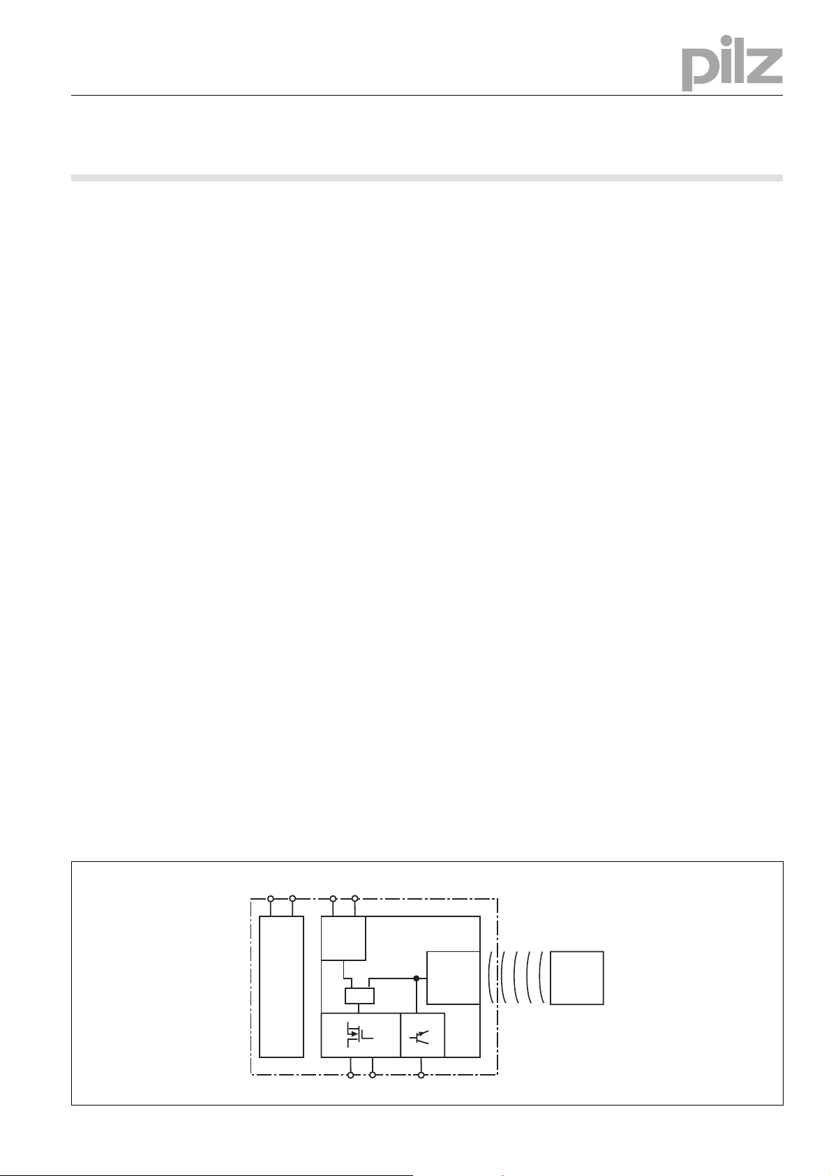
Blockschaltbild Block diagram Schéma de principe
A1 A2
Power
S11 S21
Input
&
12 22 Y32
- 1 -
Receiver
Actuator
Page 2
Funktionsbeschreibung
1080085643
Die Sicherheitsausgänge 12 und 22 leiten,
wenn
` Der Betätiger im Ansprechbereich ist und die
Eingänge S11 und S21 high sind
Der Meldeausgang Y32 leitet, wenn
` Der Betätiger im Ansprechbereich ist
Die Sicherheitsausgänge 12 und 22 sperren,
wenn
` Der Betätiger sich außerhalb des Ansprech-
bereichs befindet oder die Eingänge S11
und S21 low sind
` Das Wiedereinschalten der Ausgänge ist nur
möglich, nachdem beide Eingänge gleichzei-
tig low waren.
Die Sicherheitseingänge S11 und S21 werden
auf Plausibilität überwacht. Beide Eingänge
müssen gemeinsam aus- und einschalten (Teilbetätigungssperre).
Function description
Safety outputs 12 and 22 conduct when
` The actuator is within the response range
and inputs S11 and S21 are high
Signal output Y32 conducts when
` The actuator is within the response range
Safety outputs 12 and 22 are disabled when
` The actuator is outside the response range
or inputs S11 and S21 are low
` The outputs cannot be switched back on un-
til both inputs are low simultaneously.
Safety inputs S11 and S21 are monitored for
feasibility. Both inputs must switch off and on
together (partial operation lock).
Description du fonctionnement
Les sorties de sécurité 12 et 22 sont conductrices si
` l'actionneur est dans la zone de déclenche-
ment et les entrées S11 et S21 sont élevées
la sortie de signalisation Y32 est conductrice si
` l'actionneur est dans la zone de déclenche-
ment
Les sorties de sécurité 12 et 22 sont bloquées
si
` l'actionneur se trouve hors de la zone de dé-
clenchement ou les entrées S11 et S21 sont
faibles
` le ré-enclenchement des sorties n'est possi-
ble qu'une fois que les deux entrées aient été
faibles en même temps.
La plausibilité des entrées de sécurité S11 et
S12 est surveillée. Les deux entrées doivent
être mises hors tension et sous-tension ensemble (blocage de commande partielle).
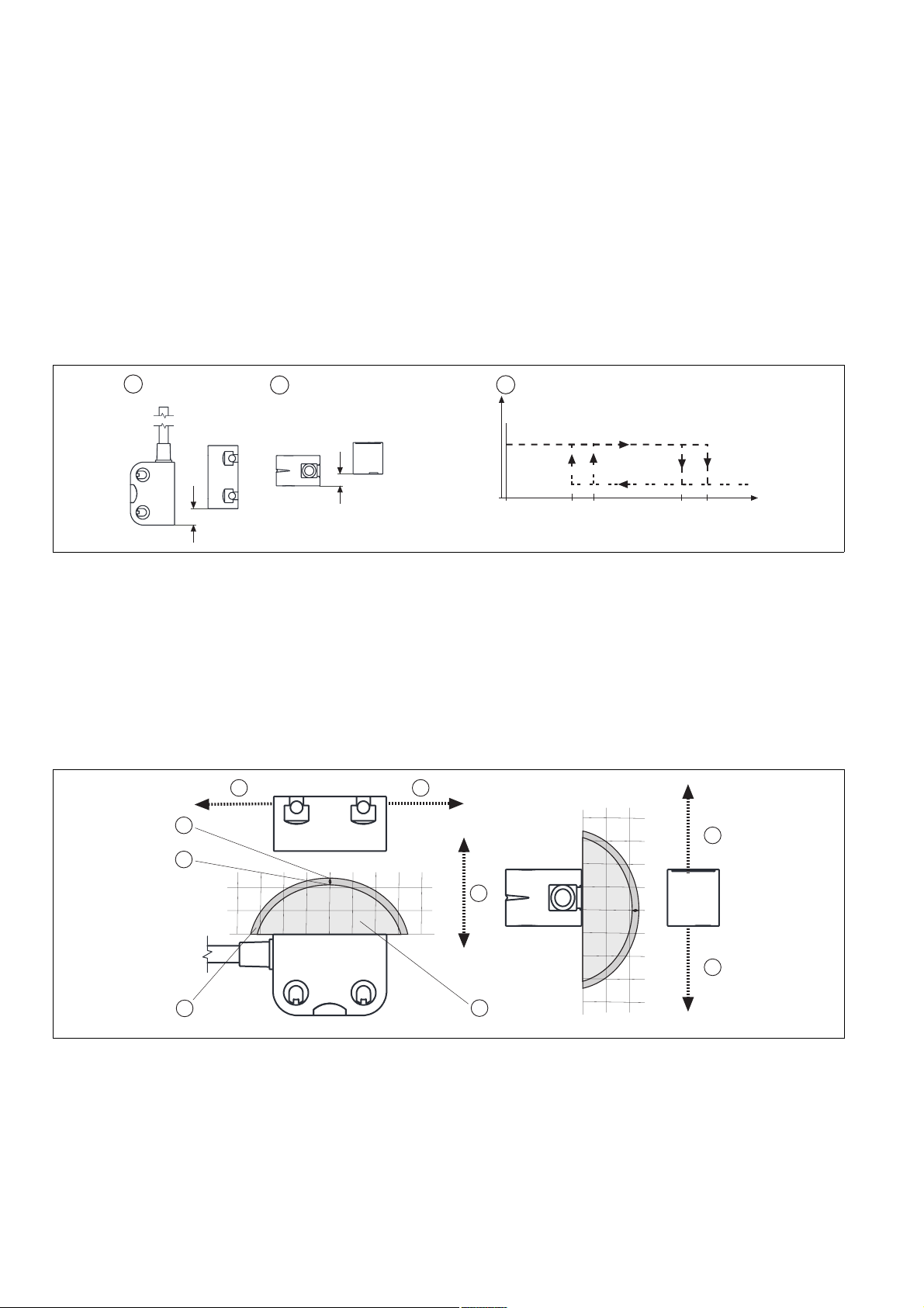
Schaltabstände Operating distances Distances de commutation
1
Legende
1091682571
` c: Seitenversatz
2
` d: Höhenversatz
` e: Schaltzustände (y-Achse) in Abhängigkeit
der Schaltabstände (x-Achse)
` Sao: Gesicherter Schaltabstand: 8,0 mm
` So: Typischer Schaltabstand: 11,0 mm
` Sr: Typischer Ausschaltabstand: 14,0 mm
` Sar: Gesicherter Ausschaltabstand: 20 mm
Ein/On/Marche
Aus/Off/Arrêt
Key
` c: Lateral offset
` d: Vertical offset
` e: Switch statuses (y-axis) dependent on
operating distances (x-axis)
` Sao: Assured operating distance: 8,0 mm
` So: Typical operating distance: 11,0 mm
` Sr: Typical release distance: 14,0 mm
` Sar: Assured release distance: 20 mm
3
y
x
s
omin
s
s
ao
Légende
o
s
r
(mm)
s
ar
` c: décalage latéral
` d: décalage en hauteur
` e: états de commutation (axe y) en fonction
des distances de commutation (axe x)
` Sao : distance de commutation de sécurité :
8,0 mm
` So : distance de commutation caractéristi-
que : 11,0 mm
` Sr : distance de déclenchement caractéristi-
que : 14,0 mm
` Sar : distance de déclenchement de sécurité
: 20 mm
Seiten- und Höhenversatz Lateral and vertical offset Décalage latéral et en hauteur
4 4
3
2
10
5
0
1
046810-4-6-8-10
mm
10
5
5
0
6
0510
0510
-10
-8
-6
-4
0
4
6
8
10
mm
4
4
Legende
1273898891
` c: Hysterese
` d: Typischer Schaltabstand S
` e: Typischer Ausschaltabstand S
O
` f: Versatz in mm
` g: Schaltabstand in mm
` h: Ansprechbereich
Key
` c: Hysteresis
` d: Typical operating distance S
r
` e: Typical release distance S
` f: Offset in mm
O
r
` g: Operating distance in mm
` h: Response range
Légende
` c: Hystérésis
` d: Distance approximative de commutation
S
O
` e: Distance approximative de déclenche-
ment S
` f: Décalage en mm
r
` g: Distance de commutation en mm
` h: Zone de déclenchement
- 2 -
Page 3
Verdrahtung
517049611
Beachten Sie:
` Angaben im Abschnitt „Technische Daten“
unbedingt einhalten.
` Berechnung der max. Leitungslänge I
Eingangskreis:
R
lmax
=
I
max
Rl / km
= max. Gesamtleitungswiderstand
R
lmax
(s. techn. Daten)
/ km = Leitungswiderstand/km
R
l
Wiring
Please note:
` Information given in the “Technical details”
must be followed.
im
` Calculation of the max. cable length l
max
the input circuit:
R
lmax
=
I
max
Rl / km
= max. overall cable resistance (see
R
lmax
Technical details)
/ km = cable resistance/km
R
l
Raccordement
Important :
` Respectez impérativement les données indi-
quées dans la partie "Caractéristiques techniques".
in
max
` Calcul de la longueur de câble max. I
le circuit d'entrée :
R
lmax
=
I
max
Rl / km
= résistance max. de l'ensemble du
R
lmax
câblage (voir les caractéristiques techniques)
/ km = résistance du câblage/km
R
l
max
sur
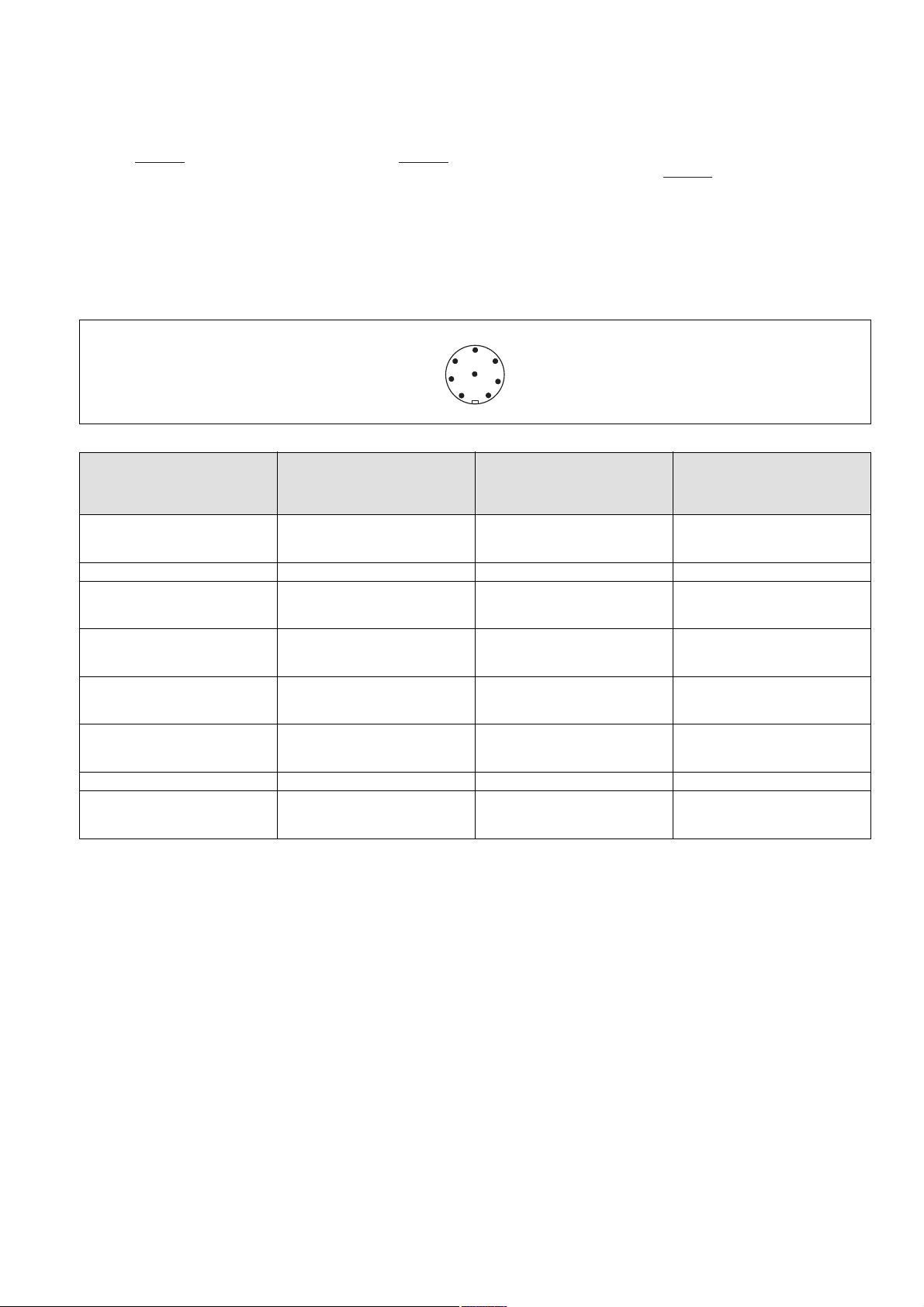
Anschlüsse Connections Raccordements
Stiftstecker 8-pol. M8/M12 (male) Connector male 8 pin M8/M12 Connecteur mâle M8/M12 à 8 broches
5
6
7
1
Anschlussbelegung Stecker und Kabel Pin assignment, connector and cable Affectation des bornes - connecteur et câble
Anschlussbezeichnung im
Blockschaltbild/
Terminal designation/
Funktion/
Function/
Foncion
Désignation des bornes
S21 Eingang Kanal 2/
Input, channel 2/
Canal d'entrée 2
A1 +24 UB 2 braun/brown/marron
12 Ausgang Kanal 1/
Output, channel 1/
Canal de sortie 1
22 Ausgang Kanal 2/
Output, channel 2/
Canal de sortie 2
Y32 Hilfsausgang/
Auxiliary output/
Sortie d'information
S11 Eingang Kanal 1/
Input, channel 1/
Canal d'entrée 1
A2 0 V UB 7 blau/blue/bleu
- nicht anschließen/
do not connect/
pas raccordé
4
8
3
2
PIN/
Broche
Adernfarbe (Pilz Kabel)/
Cable colour (Cable Pilz)/
Couleur du fil (fil de Pilz)
1 weiß/white/blanc
3 grün/green/vert
4 gelb/yellow/jaune
5 grau/grey/gris
6rosa/pink/rose
8 rot/red/rouge
- 3 -
Page 4
Anschluss an Auswertegeräte
1104750091
Bitte beachten Sie:
` das Netzteil muss den Vorschriften für Klein-
spannungen mit sicherer Trennung (SELV,
PELV) entsprechen.
` die Ein- und Ausgänge des Sicherheitsschal-
ters müssen eine sichere Trennung zu Spannungen über 60 V AC besitzen.
1090417163
ACHTUNG!
Die Sicherheitsausgänge müssen 2-kanalig weiterverarbeitet werden.
1067372427
INFO
Sicherheitsschaltgeräte mit Weitspannungsnetzteil oder in der Geräte-Variante
(AC) haben eine interne Potentialtrennung
und sind als Auswertegeräte nicht geeignet.
Connection to evaluation devices
Please note:
` The power supply must meet the regulations
for extra low voltages with safe separation
(SELV, PELV).
` the inputs and outputs of the safety switch
must have a safe separation to voltages over
60 V AC.
CAUTION!
The safety outputs must use 2-channel
processing.
INFORMATION
AC versions of safety relays or safety relays
with a universal power supply have internal
potential isolation and are unsuitable as
evaluation devices.
Raccordement aux appareils de contrôle
Tenez compte de ce qui suit :
` Cette alimentation doit être conforme aux
prescriptions relatives aux basses tensions à
séparation galvanique (SELV, PELV).
` Les entrées et les sorties du capteur de sé-
curité doivent posséder une séparation galvanique pour les tensions supérieures à
60 V AC.
ATTENTION !
Les sorties de sécurité doivent être trai-
tées par 2 canaux.
INFORMATION
Les capteurs de sécurité avec alimentation
universelle ou dans le modèle appareil (AC)
disposent d'une séparation de potentiel interne et ne sont pas adaptés comme appareils de contrôle.
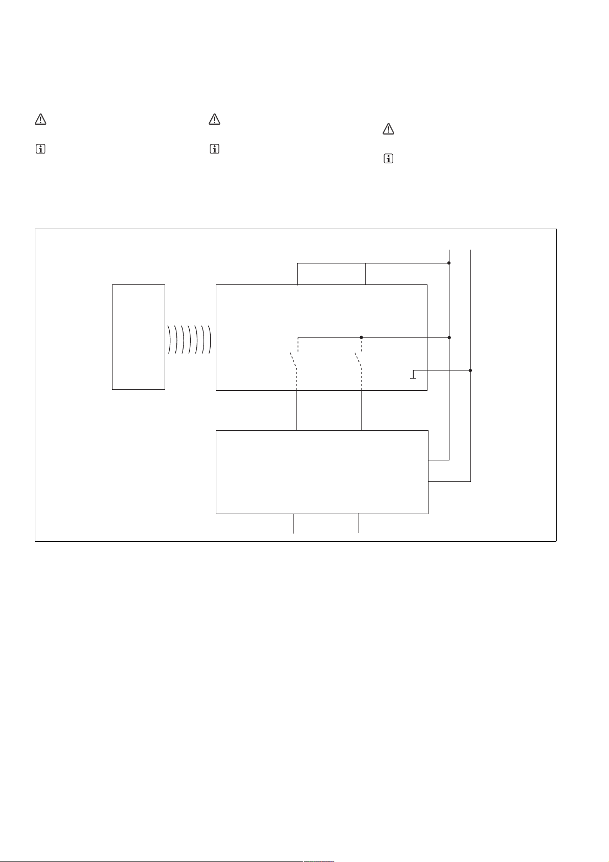
` Einzelschaltung ` Single connection ` Montage simple
24 V
0 V
Betätiger/
Actuator/
Actioneur
FS: Fail-safe
ST: Standard
S11
S21
Empfänger/
Reciever/
Recépteur
12 22
I1 (FS)
I2 (FS)
Auswertegerät/
Evaluation device/
Appareil de surveillance
A1
A2
A1
A2
- 4 -
Page 5
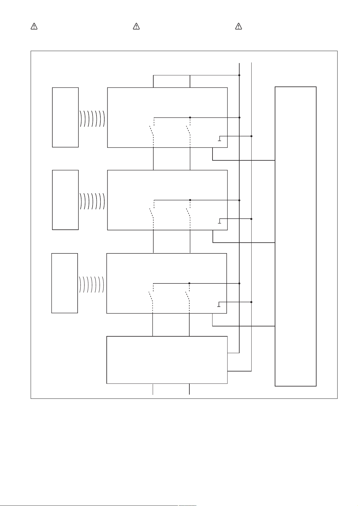
` Reihenschaltung
1022409355
ACHTUNG!
Bei Reihenschaltung mehrerer Geräte addiert sich die Rückfallverzögerung mit der
Anzahl der zwischengeschalteten Sicherheitsschalter.
Betätiger/Actuator/
Actionneur
` Series connection
CAUTION!
When several units are connected in series,
the delay-on de-energisation time increases in direct proportion to the number of interconnected safety switches.
S11
Empfänger/Receiver/
Récepteur
S21
` Montage en série
ATTENTION !
Si plusieurs appareils sont montés en série,
la temporisation à la retombée augmente
avec le nombre de capteurs de sécurité
montés.
24 V
0 V
PLC
A1
A2
Betätiger/Actuator/
Actionneur
Betätiger/Actuator/
Actionneur
12 22
S11
S21
Empfänger/Receiver/
Récepteur
12 22
S11
S21
Empfänger/Receiver/
Récepteur
12
I1 (FS)
22
I2 (FS)
Auswertegerät/
Evaluation device/
Appareil de surveillance
Y32
I1 (ST)
A1
A2
Y32
I2 (ST)
A1
A2
Y32
I3 (ST)
A1
FS: Fail-safe
ST: Standard
A2
- 5 -
Page 6

` Anschluss an PNOZ X, PNOZpower, PNOZ-
sigma, PNOZelog
` Connection to PNOZ X, PNOZpower,
PNOZsigma, PNOZelog
` Raccordement aux PNOZ X, PNOZpower,
PNOZsigma, PNOZelog
PNOZ X2.7P
PNOZ X2.8P
PNOZ X4
PNOZ X8P
PNOZ X9P
PNOZ X3P
PNOZ X3.10P
PNOZ XV3P
PNOZ XV3.1P
PNOZ
A1
A2
S21
S22
S12
S52
PNOZ
A1
A2
S21
S22
S12
S32
PSENcode
24 V
0 V
A1
2
7
A2
Y32
5
8
n.c.
S11
6
S21
1
3
12
4
22
PSENcode
24 V
0 V
A1
2
7
A2
Y32
5
8
n.c.
S11
6
S21
1
3
12
4
22
PNOZ s3
PNOZ s4
PNOZ s4.1
PNOZ s5
PNOZ X5
PNOZ X2.9P
PNOZ
A1
A2
S12
S22
PNOZ
A1
A2
S12
S52
PSENcode
24 V
0 V
A1
2
7
A2
Y32
5
8
n.c.
S11
6
S21
1
3
12
4
22
PSENcode
24 V
0 V
A1
2
7
A2
Y32
5
8
n.c.
S11
6
S21
1
3
12
4
22
- 6 -
Page 7

PNOZ X10.1
PNOZ X10.11P
PNOZ
A1
A2
S21
S22
S12
Y3
PSENcode
24 V
0 V
A1
2
7
A2
Y32
5
8
n.c.
S11
6
S21
1
3
12
4
22
PNOZ e1.1p
PNOZ e1vp
PNOZ e6.1p
PNOZ e6vp
PNOZ e5.11p
PNOZ e5.13p
PNOZ
A1
A2
Y4
S11
S12
S22
PNOZ
A1
A2
Y37
S11
S12
S22
PSENcode
24 V
0 V
A1
2
7
A2
Y32
5
8
n.c.
S11
6
S21
1
3
12
4
22
PSENcode
24 V
0 V
A1
2
7
A2
Y32
5
8
n.c.
S11
6
S21
1
3
12
4
22
` Anschluss an PNOZmulti ` Connection to PNOZmulti ` Raccordement au PNOZmulti
PNOZmulti PSENcode
Schutztür/safety gate/protecteur mobile
Schaltertyp 3/switch type 3/type du capteur 3
I0, I1: Eingänge OSSD/inputs OSSD/entrées OSSD
I2: Meldeeingang/signal input/entrée d'information
grün/green/vert
I0
gelb/yellow/jaune
I1
grau/grey/gris
I2
12
` Anschluss an PSS ` Connection to PSS ` Raccordement au PSS
PSS PSENcode
Schutztür/safety gate/protecteur mobile
Standardbaustein SB64/standard block SB64/bloc standard SB64
I00, I01: Eingänge OSSD/inputs OSSD/entrées OSSD
I02: Meldeeingang/signal input/entrée d'information
I00
I01
I02
- 7 -
grün/green/vert
gelb/yellow/jaune
grau/grey/gris
12
22
Y32
22
Y32
Page 8

Einlernen des Betätigers
1046768779
Erstmaliges Einlernen des Betätigers:
Der erste vom Sicherheitsschalter erkannte Betätiger (PSEN cs4.1) wird automatisch eingelernt, sobald er in den Ansprechbereich
gebracht wird.
Einlernen eines neuen Betätigers:
` Bringen Sie den einzulernenden Betätiger als
einzigen Transponder in den Ansprechbereich des Sicherheitsschalters. Sobald der
Betätiger erkannt wird, wechselt die LED
"Safety Gate" auf gelbes Blinklicht.
` Nach einer Wartezeit von 20 s wechselt die
LED "Safety Gate" auf gelbes Blitzen. Lösen
Sie innerhalb der nächsten 120 s durch Unterbrechen der Stromversorgung einen Systemreset aus.
` Nach Wiedereinschalten des Geräts ist der
Lernvorgang erfolgreich beendet und die Anzahl noch erlaubter weiterer Lernvorgänge
wird um 1 vermindert.
` Es sind maximal 8 Lernvorgänge möglich.
WICHTIG
Der Betätiger darf während des Einlernvorgangs nicht entfernt werden.
INFO
Ein erneutes Einlernen dieses Betätigers
am selben Sicherheitsschalter ist nicht
mehr möglich.
Montage
1086339595
` Montieren Sie Sicherheitsschalter und Betä-
tiger parallel gegenüberliegend.
ACHTUNG!
Eine Umgebung mit elektrisch oder magnetisch leitfähigem Material kann die Geräteeigenschaften beeinflussen. Prüfen Sie die
Schaltabstände und den gesicherten Abschaltabstand.
` Befestigen Sie Sicherheitsschalter und Betä-
tiger ausschließlich mit Schrauben M4 mit
flacher Kopfunterseite (z.B. M4-Zylinderkopf- oder -Flachkopfschrauben).
INFO
Sichern Sie den Betätiger gegen unbefugtes Entfernen und vor Verschmutzung. Verschließen Sie die Montageöffnungen mit
den mitgelieferten Verschlüssen.
INFO
Verschluss (1) entspricht den UL-Anforderungen, Verschluss (4) entspricht nicht den
UL-Anforderungen.
` Anzugsdrehmoment max. 0,8 Nm.
` Beachten Sie unbedingt den Abstand zwi-
schen zwei Sicherheitsschaltern (siehe Technische Daten).
Sicherheitsschalter und Betätiger
` keinen starken Stößen oder Schwingungen
aussetzen
` nicht als Anschlag benutzen
Teaching in the actuator
Teaching in the actuator for the first time:
The first actuator (PSEN cs4.1) detected by the
safety switch is automatically taught in as soon
as it is brought into the response range.
To teach in a new actuator:
` The actuator that is to be taught in must be
brought into the safety switch's response
range as the only transponder. As soon as
the actuator is detected, the "Safety Gate"
LED switches to a yellow flashing light.
` After 20 s has elapsed, the "Safety Gate"
LED switches to quick yellow flashes. Trigger
a system reset in the next 120 s by interrupting the power supply.
` When the device is switched back on, the
learning procedure is complete and the
number of permitted additional learning procedures is reduced by 1.
NOTICE
The actuator must not be removed during
the learning procedure.
INFORMATION
The actuator cannot be retaught on the
same safety switch.
Installation
`
The safety switch and actuator should be installed opposite each other in parallel.
CAUTION!
The unit's properties may be affected if installed in an environment containing electrically or magnetically conductive material.
Please check the operating distances and
the assured release distance.
` Safety switches and actuators should only
be secured using M4 screws with a flat head
(e.g. M4 cheese-head or pan head screws).
INFORMATION
The actuator should be protected from unauthorised removal and from contamination. Close the mounting holes using the
seals provided.
INFORMATION
Seal (1) meets UL requirements; seal (4)
does not meet UL requirements.
` Torque setting max. 0.8 Nm.
` The distance between two safety switches
must be maintained (see Technical details).
Safety switches and actuators
` Should not be exposed to heavy shock or vi-
bration
` Should not be used as a limit stop
Programmation de l'actionneur par apprentissage
Première programmation de l'actionneur :
Le premier actionneur reconnu par le capteur
de sécurité (PSEN cs4.1) est automatiquement
programmé dès qu'il entre dans la zone de déclenchement.
Programmation d'un nouvel actionneur :
` Amenez l'actionneur à programmer dans la
zone de déclenchement du capteur de sécurité. Aucun autre transpondeur ne doit se
trouver dans cette zone. Dès que l'actionneur est reconnu, la LED « Safety Gate »
commence à clignoter en jaune.
` Après un délai d'attente de 20 s, la LED
« Safety Gate » commence à émettre des
flashs jaunes. Dans les 120 s qui suivent, déclenchez une remise à zéro du système en
coupant l'alimentation électrique.
` Le processus d'apprentissage est terminé
avec succès lorsque vous remettez l'appareil
sous tension. Le nombre de processus d'apprentissage encore autorisés est alors réduit
de 1.
IMPORTANT
Ne pas retirer l'actionneur de la zone de déclenchement durant le processus d'apprentissage.
INFORMATION
Une nouvelle programmation de l'actionneur n'est plus possible sur le même capteur de sécurité.
Montage
`
Montez le capteur de sécurité et l'actionneur
l'un en face de l'autre de manière parallèle.
ATTENTION !
Un environnement avec des matériaux
conducteurs de l'électricité ou du magnétisme peut affecter les caractéristiques de
l'appareil. Veuillez vérifier les distances de
commutation et la distance de déclenchement de sécurité.
` Pour fixer le capteur de sécurité et l'action-
neur, utilisez uniquement des vis M4 dont la
tête présente une face inférieure plate (par
ex. vis M4 cylindriques ou à tête plate).
INFORMATION
Assurez-vous que l'actionneur ne puisse
être ni retiré sans autorisation, ni encrassé.
Refermez les ouvertures du montage à
l'aide des fermetures fournies.
INFORMATION
La fermeture (1) correspond aux exigences
UL ; la fermeture (4) ne correspond aux
exigences UL.
` Couple de serrage max. 0,8 Nm.
` Veuillez absolument respecter la distance
entre les capteurs de sécurité (voir les caractéristiques techniques).
Le capteur de sécurité et l'actionneur
` ne doivent pas subir des chocs et vibrations
importants
` ne doivent pas être utilisés comme butée
- 8 -
Page 9

Montage Variante 1
1086268427
` 1. Gewinde (M4) in gewünschter Position
schneiden.
` 2. Sensor mit einer Schraube fixieren.
` 3. Zweite Schraube in Sensor eindrehen.
(Wichtig: Schrauben nicht fest anziehen).
Schrauben für Betätiger eindrehen, dabei
den Abstand Schraubenkopf zur Auflage beachten: ca. 3 ... 6 mm.
` 4. Betätiger zu Sensor ausrichten.
INFO
Die beschriftete Fläche des Betätigers (aktive Fläche) muss zum Sensor zeigen.
` 5. Betätiger auf die Schrauben schieben.
` 6. Sensor ausrichten und die Schrauben mit
max. 0,8 Nm anziehen.
` 7. Betätiger ausrichten und die Schrauben
mit max. 0,8 Nm anziehen.
` 8. Verwendete Montageöffnungen mit Ver-
schluss (1) oder (4) schließen.
` 9. Nicht verwendete Montageöffnungen mit
Verschluss (2) schließen.
` 10. Montageöffnungen auf aktiver Fläche mit
Verschluss (3) schließen.
` 11. Sensor und Betätiger sind fertig montiert.
Installation type 1
` 1. Cut the thread (M4) in the required posi-
tion.
` 2. Use a screw to fix the sensor.
` 3. Attach the second screw to the sensor.
(Important: do not tighten the screws). Attach
the screws for the actuator, maintaining the
distance between the screw head and the
plate: ca. 3 ... 6 mm
` 4. Align actuator to sensor.
INFORMATION
The inscribed area on the actuator (active
surface) must point to the sensor.
` 5. Slide the actuator on to the screws.
` 6. Align the sensor and tighten the screws to
a max. 0.8 Nm.
` 7. Align the actuator and tighten the screws
to a max. 0.8 Nm.
` 8. Close used mounting holes using seal (1)
or (4).
` 9. Close unused mounting holes using seal
(2).
` 10. Close mounting holes on the sensing
face using seal (3).
` 11. Installation of sensor and actuator is now
complete.
Montage du modèle 1
` 1. Couper le filetage (M4) dans la position
souhaitée.
` 2. Fixer le capteur à l'aide d'une vis.
` 3. Visser la deuxième vis dans le capteur.
(Important : ne pas serrer les vis à fond). Visser les vis pour l'actionneur, pour cela, respecter la distance entre la tête de vis et
l'application : env. 3 à 6 mm
` 4. Orienter l'actionneur par rapport au cap-
teur.
INFORMATION
La surface de l'actionneur avec une inscription (surface active) doit être orientée vers
le capteur.
` 5. Pousser l'actionneur sur les vis.
` 6. Orienter le capteur et serrer les vis avec
max. 0,8 Nm.
` 7. Orienter l'actionneur et serrer les vis avec
max. 0,8 Nm.
` 8. Refermer les ouvertures destinées au
montage à l'aide des fermetures (1) ou (4).
` 9. Refermer les ouvertures non utilisées pour
le montage à l'aide de la fermeture (2).
` 10. Refermer les ouvertures destinées au
montage, situées sur la surface active, à
l'aide de la fermeture (3).
` 11. Le capteur et l'actionneur sont à présent
montés.
1
4
7
2
5
8
3
6
9
10
11
4
3
2
1
- 9 -
Page 10

Montage Variante 2
1086273035
Montieren Sie den Sensor wie bei Montage Variante 1
` 1. Schrauben für Betätiger eindrehen, dabei
den Abstand Schraubenkopf zur Auflage beachten: ca. 3 ... 6 mm.
` 2. Nicht verwendete Montageöffnungen, die
auf der Auflagefläche aufliegen, mit Verschluss (2) schließen.
` 3. Betätiger auf die Schrauben schieben.
` 4. Betätiger ausrichten und die Schrauben
mit max. 0,8 Nm anziehen.
` 5. Verwendete Montageöffnungen mit Ver-
schluss (1) oder (4) schließen.
` 6. Montageöffnungen auf aktiver Fläche mit
Verschluss (3) schließen.
` 7. Sensor und Betätiger sind fertig montiert.
Installation type 2
Install the sensor as shown for installation type
1
` 1. Attach the screws for the actuator, main-
taining the distance between the screw head
and the plate: ca. 3 ... 6 mm.
` 2. Close unused mounting holes on the plate
using seal (2).
` 3. Slide the actuator on to the screws.
` 4. Align the actuator and tighten the screws
to a max. 0.8 Nm.
` 5. Close used mounting holes using seal (1)
or (4).
` 6. Close mounting holes on the sensing face
using seal (3).
` 7. Installation of sensor and actuator is now
complete.
Montage du modèle 2
Montez le capteur de la même manière que
pour le modèle 1
` 1. Visser les vis pour l'actionneur, pour cela,
respecter la distance entre la tête de vis et
l'application : env. 3 à 6 mm.
` 2. Refermer à l'aide de la fermeture (2) les
ouvertures non utilisées pour le montage qui
se trouvent dans la surface d'application.
` 3. Pousser l'actionneur sur les vis.
` 4. Orienter l'actionneur et serrer les vis avec
max. 0,8 Nm.
` 5. Refermer les ouvertures destinées au
montage à l'aide des fermetures (1) ou (4).
` 6. Refermer les ouvertures destinées au
montage, situées sur la surface active, à
l'aide de la fermeture (3).
` 7. Le capteur et l'actionneur sont à présent
montés.
1
4
7
2
5
4
3
2
1
3
6
Justage
1086401675
` Prüfen Sie die Funktion immer mit einem der
zugelassenen Auswertegeräte
` Die angegebenen Schaltabstände (siehe
technische Daten) gelten nur, wenn Sicherheitsschalter und Betätiger parallel gegenüberliegend montiert sind. Andere
Anordnungen können zu abweichenden
Schaltabständen führen.
` Beachten Sie den maximal zulässigen Sei-
ten- und Höhenversatz (siehe "Schaltabstände" und "Seiten- und Höhenversatz").
Adjustment
Always test the function with one of the ap-
`
proved evaluation devices
` The stated operating distances (see Techni-
cal details) only apply when the safety switch
and actuator are installed facing each other
in parallel. Operating distances may deviate
if other arrangements are used.
` Note the maximum permitted lateral and ver-
tical offset (see "Operating distances" and
"Lateral and vertical offset").
- 10 -
Ajustement
Vérifiez la fonction uniquement avec l'un des
`
appareils de contrôle homologués.
` Les distances de commutation mentionnées
dans les caractéristiques techniques sont
valables uniquement lorsque le capteur de
sécurité et l'actionneur sont montés l'un en
face de l'autre de manière parallèle. D'autres
montages peuvent conduire à des distances
de commutation divergentes.
` Respectez le décalage latéral et en hauteur
maximal autorisé (voir « Distances de
commutation » et « Décalage latéral et en
hauteur maximum »).
Page 11

Betrieb
1086405899
Prüfen Sie vor der Inbetriebnahme die Funktion
des Sicherheitsschalters.
Statusanzeigen:
LED "POWER/Fault" leuchtet grün: Gerät ist
`
betriebsbereit
` LED "Safety Gate" leuchtet gelb: Betätiger
befindet sich im Ansprechbereich
` LED "Input" leuchtet gelb: Eingangskreise
sind geschlossen oder ein HIGH-Signal liegt
an
Fehleranzeige:
LED "Input" blinkt gelb: nur ein Kanal des
`
Eingangskreises offen (Teilbetätigung)
Abhilfe: beide Kanäle des Eingangskreises
öffnen
` LED "POWER/Fault" leuchtet rot: Fehlermel-
dung.
An den LEDS "Safety Gate" und "Input" werden Blinkcodes zur Fehlerdiagnose ausgegeben (siehe Technischer Katalog PSENmag
und PSENcode).
Abhilfe: Fehler beheben und Stromversorgung unterbrechen.
Operation
Check the function of the safety switch before
commissioning.
Status indicators:
"POWER/Fault" LED lights up green: The unit
`
is ready for operation
` "Safety Gate" LED lights up yellow: Actuator
is within the response range
` "Input" LED lights up yellow: Input circuits
are closed or a HIGH signal is present
Fault indicator:
"Input" LED lights up yellow: Only one chan-
`
nel of the input circuit open (partial operation)
Remedy: Open both channels of the input
circuit
` "POWER/Fault" LED lights up red: Error
message.
Flashing codes for fault diagnostics are output to the "Safety Gate" and "Input" LEDs
(see technical catalogue PSENmag and
PSENcode).
Remedy: Rectify fault and interrupt power
supply.
Fonctionnement
Avant la mise en service, veuillez vérifer la fonction du capteur de sécurité.
Affichages d'état :
La LED "POWER/Fault" s'allume en vert :
`
l'appareil est opérationnel
` La LED « Safety Gate » s'allume en jaune :
l'actionneur est dans la zone de déclenchement
` La LED « Input » s'allume en jaune : les cir-
cuits d'entrée sont fermés ou présence d'un
signal Haut
Affichage d'erreurs :
` La LED « Input » clignote en jaune : un seul
canal du circuit d'entrée est ouvert (commande partielle)
Remède : ouvrir les deux canaux du circuit
d'entrée
` La LED "POWER/Fault" s'allume en rouge :
message d'erreur.
Des codes clignotants servant au diagnostic
des erreurs sont émis par les LED "Safety
Gate" et "Input" (voir le catalogue technique
PSENmag et PSENcode).
Remède : éliminer le défaut et couper l'alimentation électrique.
Abmessungen Dimensions Dimensions
PSEN cs4.1a PSEN cs4.1a PSEN cs4.1a
Safety switch
Actuator
18
19
8
5
2
7
,
3
2
4
8
R
26,4
14,4
18
5
,
4
7
2
3
2
14,4
18
- 11 -
Page 12

PSEN cs4.1p PSEN cs4.1p PSEN cs4.1p
8M
9
,
3
3
5
2
5
0
5
1
Safety switch
5
7
2
,
3
2
4
Actuator
19
8
14,4
5
,
4
223
14,4
7
PSEN cs4.1 M12/8-0.15m
130 5
18
PSEN cs4.1 M12/8-0.15m PSEN cs4.1 M12/8-0.15m
1272150027
8
R
26,4
18 18
Safety switch
12M
8
,
6
6
4
3
Actuator
19
8
5
2
7
,
2
3
4
14,4
5
,
4
2
2
14,4
7
3
18
8
R
26,4
18
18
Technische Daten Technical details Caractéristiques techniques
Elektrische Daten Electrical data Données électriques
Versorgungsspannung UBDC Supply voltage UB DC Tension d'alimentation UBDC 24 V
Spannungstoleranz Voltage tolerance Plage de la tension d'alimentation -20 %/+20 %
Leistungsaufnahme bei U
DC Power consumption at UB DC Consommation UBDC 1,0 W
B
Max. Einschaltstromimpuls Max. inrush current impulse Impulsion de courant max. lors de
la mise sous tension
A1 A1 A1 0,58 A
Impulsdauer Pulse duration Durée d'impulsion 1,0000 ms
Spannung an Eingängen Voltage at inputs Tension sur entrées 24 V DC
Strom pro Eingang Current per input Courant par entrée 5,0 mA
Schaltstrom pro Ausgang Switching current per output Intensité de commutation par sortie 100 mA
- 12 -
Page 13

Elektrische Daten Electrical data Données électriques
Schaltleistung pro Ausgang Breaking capacity per output Puissance de commutation par sor-
2,4 W
tie
Max. Schaltfrequenz Max. switch frequency Fréquence de commutation max. 3 Hz
Halbleiterausgänge (kurz-
schlussfest)
Semiconductor outputs (short circuit proof)
Sorties statiques (protégées contre
les courts-circuits)
Sicherheitsausgänge OSSD OSSD safety outputs Sorties de sécurité OSSD 2
Meldeausgänge Signal outputs Sorties d'information 1
Max. Gesamtleitungswiderstand R
im Eingangskreis
max
Max. Leitungskapazität an den Sicherheitsausgängen
Max. overall cable resistance R
l-
in the input circuit
Max. line capacitance at the safety
outputs
Leerlauf, PNOZ mit Relaiskontakten No-load, PNOZ with relay contacts Fonctionnement à vide, PNOZ avec
Résistance max. de l'ensemble du
lmax
câblage R
trée
dans le circuit d'en-
lmax
Capacité max. du câblage sur les
sorties de sécurité
1000 Ohm
400 nF
contacts de relais
PNOZmulti, PNOZelog, PSS PNOZmulti, PNOZelog, PSS PNOZmulti, PNOZelog, PSS 400 nF
Zeiten Times Temporisations
Überbrückung bei Spannungseinbrüchen
Supply interruption before deenergisation
Tenue aux micro-coupures 10,0 ms
Einschaltverzögerung Switch-on delay Temps de montée
nach Anlegen von U
B
after applying U
B
après application de U
B
1,0 s
Eingänge typ. Input typ. Entrées env. 13 ms
Eingänge max. Input max. Entrées max. 20 ms
Betätiger typ. Actuator typ. Actionneur env. 45 ms
Betätiger max. Actuator max. Actionneur max. 120 ms
Rückfallverzögerung Delay-on de-energisation Temps de retombée
Eingänge typ. Input typ. Entrées env. 15 ms
Eingänge max. Input max. Entrées max. 20 ms
Betätiger typ. Actuator typ. Actionneur env. 40 ms
Betätiger max. Actuator max. Actionneur max. 260 ms
Testimpulsdauer Sicherheitsaus-
gänge
Test pulse duration on safety outputs
Durée du test impulsionnel pour les
sorties de sécurité
300 µs
Gleichzeitigkeit Kanal 1 und 2 Simultaneity, channel 1 and 2 Simultanéité des canaux 1 et 2 ∞
Umweltdaten Environmental data Données sur l'environnement
EMV EMC CEM EN 55011: class A,
EN 61000-4-2, EN 61000-4-3,
EN 61000-4-4, EN 61000-4-6,
EN 61000-4-8
Schockbeanspruchung Shock stress Résistance aux chocs 30g , 18 ms
Schwingungen nach EN 60947-5-2 Vibration to EN 60947-5-2 Vibrations selon EN 60947-5-2
Frequenz Frequency Fréquence 10 - 55 Hz
Amplitude Amplitude Amplitude 0,35 mm
Verschmutzungsgrad Pollution degree Niveau d'encrassement 3
Bemessungsisolationsspannung Rated insulation voltage Tension assignée d'isolement 75 V
Bemessungsstoßspannungsfestig-
keit
Rated impulse withstand voltage Tension assignée de tenue aux
chocs
1,00 kV
Überspannungskategorie Overvoltage category Catégorie de surtensions III
Umgebungstemperatur Ambient temperature Température d'utilisation -25 - 70 °C
Lagertemperatur Storage temperature Température de stockage -25 - 70 °C
Mechanische Daten Mechanical data Données mécaniques
Hysterese typ. Hysteresis typ. Hystérésis env. 2,0 mm
Gesicherter Schaltabstand S
Gesicherter Ausschaltabstand S
Typischer Schaltabstand S
Ausschaltabstand S
o
r
Min. Abstand zwischen Sicherheitsschaltern
Assured operating distance S
ao
Assured release distance S
ar
Typical switching distance S
Release distance S
Min. distance between safety
switches
Distance de commutation de sécu-
ao
rité S
ao
ar
r
Distance de déclenchement de sécurité S
ar
Distance de commutation caracté-
o
ristique S
o
Distance de déclenchement S
Distance minimale entre les cap-
r
8,0 mm
20 mm
11,0 mm
14,0 mm
100 mm
teurs de sécurité
Zugehörige Betätiger Corresponding actuator Actionneurs correspondants PSEN cs4.1
Anschlussart Connection type Type de connection 5 m Kabel, 5 m cable, 5 m câ-
ble No. 541111
M12, 8-pol. Stiftstecker (male) ,
Connector male 8 pin M12,
Connecteur mâle M12 à 8 broches No. 541109
M8, 8-pol. Stiftstecker (male),
Connector male 8 pin M8,
Connecteur mâle M8 à 8 broches No. 541110
Leitung Cable Câble LiYY 8 x 0,14 mm
2
- 13 -
Page 14

Mechanische Daten Mechanical data Données mécaniques
Schutzart Protection type Indice de protection IP67 No. 541109, 541110
IP6K9K No. 541111
Material Material Matériau
Gehäuse Housing Boîtier PBT
Abmessungen siehe Abbildung Dimensions, see graphic Dimensions, voir l'illustration
Gewicht Weight Poids
Sensor Sensor Capteur 230 g No. 541111
35 g No. 541109, 541110
Betätiger Actuator Actionneur 15 g
Sicherheitstechnische Kenndaten
PL nach EN ISO 13849-1: 2006 PL in accordance with EN ISO
Safety-related characteristic
data
Caractéristiques techniques de
sécurité
PL selon EN ISO 13849-1: 2006 PL e (Cat. 4)
13849-1: 2006
Kategorie nach EN 954-1 Category in accordance with EN
Catégorie selon EN 954-1 Cat. 4
954-1
SIL CL nach EN IEC 62061 SIL CL in accordance with EN IEC
SIL CL selon EN IEC 62061 SIL CL 3
62061
PFH nach EN IEC 62061 PFH in accordance with EN IEC
PFH selon EN IEC 62061 2,62E-09
62061
SIL nach IEC 61511 SIL in accordance with IEC 61511 SIL selon IEC 61511 SIL 3
PFD nach IEC 61511 PFD in accordance with IEC 61511 PFD selon IEC 61511 7,68E-05
[Jahr] nach EN ISO 13849-1:
T
M
2006
Es gelten die 2009-01 aktuellen Ausgaben der
Normen.
TM [year] in accordance with EN
ISO 13849-1: 2006
The standards current on 2009-01 apply. Les versions actuelles 2009-01 des normes
TM [année] selon EN ISO 13849-1:
2006
s'appliquent.
20
- 14 -
Page 15

Bestelldaten Order reference Références
Typ/Type/Type Stück/
Quantity/
Nombre
PSEN cs4.1a/PSEN cs4.1 1/1 Transpondertechnik/Trans-
PSEN cs4.1p/PSEN cs4.1 1/1 Transpondertechnik/Trans-
PSEN cs4.1 M12/8-0.15m/PSEN
1/1 Transpondertechnik/Trans-
cs4.1
Wirkweise/Operation/Actionnement
ponder technology/Technique
à transpondeur
ponder technology/Technique
à transpondeur
ponder technology/Technique
à transpondeur
Merkmale/Features/ Caractéristiques
Sicheres Schutztürsystem, vollcodiert/Safety gate system, fully coded/Système de sécurité pour
protecteurs mobiles, précodé
Sicheres Schutztürsystem, vollcodiert/Safety gate system, fully coded/Système de sécurité pour
protecteurs mobiles, précodé
Sicheres Schutztürsystem, vollcodiert/Safety gate system, fully coded/Système de sécurité pour
protecteurs mobiles, précodé
Bestell-Nr./Order
no./Référence
541 111
541 110
541 109
PSEN cs4.1a (switch) 1 Transpondertechnik/Trans-
ponder technology/Technique
à transpondeur
PSEN cs4.1p (switch) 1 Transpondertechnik/Trans-
ponder technology/Technique
à transpondeur
PSEN cs4.1 M12/8-0.15m (switch) 1 Transpondertechnik/Trans-
ponder technology/Technique
à transpondeur
PSEN cs4.1 1 Transpondertechnik/Trans-
ponder technology/Technique
à transpondeur
EG-Konformitätserklärung
1139424011
Diese(s) Produkt(e) erfüllen die Anforderungen
der Richtlinie 2006/42/EG über Maschinen des
europäischen Parlaments und des Rates. Die
vollständige EG-Konformitätserklärung finden
Sie im Internet unter www.pilz.com.
Bevollmächtigter: Norbert Fröhlich, Pilz GmbH
& Co. KG, Felix-Wankel-Str. 2, 73760 Ostfildern, Deutschland
22187-3FR-012011-03Printed in Germany
EC Declaration of Conformity
This (these) product(s) comply with the requirements of Directive 2006/42/EC of the European
Parliament and of the Council on machinery.
The complete EC Declaration of Conformity is
available on the Internet at www.pilz.com.
Authorised representative: Norbert Fröhlich,
Pilz GmbH & Co. KG, Felix-Wankel-Str. 2,
73760 Ostfildern, Germany
Sicherheitsschalter, vollcodiert/Safety switch, fully coded/Capteur de sécurité, précodé
Sicherheitsschalter, vollcodiert/Safety switch, fully coded/Capteur de sécurité, précodé
Sicherheitsschalter, vollcodiert/Safety switch, fully coded/Capteur de sécurité, précodé
Betätiger, codiert/Actuator, coded/
Actionneur, codé
Déclaration de conformité CE
Ce(s) produit(s) satisfait (satisfont) aux exigences de la directive 2006/42/CE relative aux machines du Parlement Européen et du Conseil.
Vous trouverez la déclaration de conformité CE
complète sur notre site internet www.pilz.com.
Représentant : Norbert Fröhlich, Pilz GmbH &
Co. KG, Felix-Wankel-Str. 2, 73760 Ostfildern,
Allemagne
541 161
541 160
541 159
541 180
Originalbetriebsanleitung/Original instructions/Notice originale
22187-3FR-01, 2011-03 Printed in Germany Printed in Germany
 Loading...