

Electronic Monitoring Relays
True power monitoring for Interbus
P1WX-IBS
Technical Details P1WX-IBS
Electrical data
Supply voltage DC: 24 V
Tolerance 85 ... 125 %
Power consumption Approx. 2.5 W
Measuring circuit
Measuring voltage
Frequency range 15 ... 400 Hz
Adjustable measurement range limit values
Max. overload AC, DC: 40 A/3 s
Start-up delay time 0 ... 25.5 s, adjustable in 255 increments
Measuring accuracy P: < ±2 %
True power monitor for Interbus
Digital resolution 8 bit (external), 10 bit (internal)
Features
● Communication via Interbus-S
(in accordance with
DIN E 19258), remote bus,
RS 485
● Slave connection
● Polls true power, apparent
current, voltage, diagnostic and
statistical data via the controller
● Currents can be measured in
4 different measuring current
ranges
● Large voltage measurement
range
● Suitable for use with frequencycontrolled motors
● Measurement principle: Aron
circuit
● Suitable for current transformers
Approvals
P1WX-IBS
●
Reaction time 30 ... 80 ms (complete periods)
Requirements for current transformer I = 5 A: 2,5 ... 15 VA, Class 3
Interbus bus data (Remote bus, 4 words)
Mechanical data
Max. cable cross section 1 x 2.5 mm2 or 2 x 1.5 mm
of external conductor single-core or multi-core with crimp
Dimensions (H x W x D) 75 x 45 x 124 mm
Weight 280 g
Description
The P1WX-IBS true power monitor is
enclosed in a 45 mm wide P-93
housing. There are 3 versions with
different voltage ranges available.
Each version can
- monitor either a three-phase load,
- two AC loads
or
- two DC loads.
Features:
● Status LEDs are in accordance
with guidelines of the Interbus
Club
● Currents can be measured in
4 different measuring current
ranges, 25 mA ... 10 A
● Switch thresholds for under and
overload can be set separately
● Max. 4 adjustable switching
thresholds
● Hysteresis can be set for each
switching threshold
● “Teach-in” mode to establish ideal
process settings or threshold
values
● Reset latch
● Start-up delay time ta can be set
● Non-volatile mekory of set values
(50 different parameter sets)
AC/DC: 10 ... 70, 60 ... 450, 100 ... 750 V
AC: 0.5; 1; 5; 10 A
DC: 5, 10 A
U, I: < ±5 %
2
connector
● Detects values which exceed
measurement range (current and
voltage)
● Measurement principle: Aron
circuit (rated true power without
neutral conductor monitor)
● For currents > 10 A: Current
transformer input
The P1WX-IBS monitors the rated
true power of electrical loads. It is
intended for use in industrial environments and is characterised by its
bus capabilities. The P1WX-IBS is
designed as an Interbus slave
connection for the remote bus.
4
Pilz GmbH & Co. KG, Sichere Automation, Felix-Wankel-Straße 2, 73760 Ostfildern, Germany
Telephone +49 711 3409-0, Telefax +49 711 3409-133, E-Mail: pilz.gmbh@pilz.de
NSG-D-2-237-2005-04
Electronic Monitoring Relays
True power monitoring for Interbus
P1WX-IBS
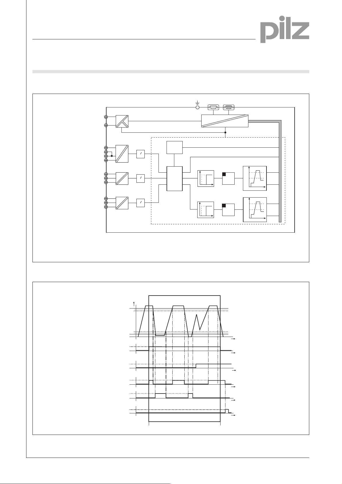
Internal wiring diagram
(+24 V DC)
A1(+)
(GND)
A2 (-)
U
B
RS-485
Interbus
IN OUT
SUPI 3
4
UBSupply voltage
UMMeasuring voltage
I1, I2Measuring current
Timing diagram
L1/+
LL2/N
L3/+
K1
U/5
U/10
K3
W/5
W/10
Switch threshold S1
(upper limit)
U
M
I
1
I
2
Diagnostic
statistics
»
U
»
U
»
U
t
Start-up delay time
a
S1... S4 Switching thresholds
P
p = u x i
µ-Controller
Measuring window
t
delay
t
delay
Diagnostic data
Instantaneous values p, u, i
a
a
Reset
latch
Reset
latch
Hysteresis
P
S1
S2
P
S3
S4
S1
S2
t
S3
S4
t
Switch threshold S2
(lower limit)
Measurement Start
Result of
threshold evaluation S1
Result of
threshold evaluation S2
Reset the
threshold status
Stop
Reset latch
Use
Do not use
Start power measuring
Stop measuring
Pilz GmbH & Co. KG, Sichere Automation, Felix-Wankel-Straße 2, 73760 Ostfildern, Germany
Telephone +49 711 3409-0, Telefax +49 711 3409-133, E-Mail: pilz.gmbh@pilz.de
Hysteresis
t
t
t
t
t
t
NSG-D-2-237-2005-04

Electronic Monitoring Relays
True power monitoring for Interbus
P1WX-IBS
Connection examples
● Example 1
Monitoring true power on a three-phase load with a current measurement
range 0.5 A/5 A
L1
U
L2
M
L3
0 V
PA
U
B
24 V DC
Fuse
L2/
L-
A1
L1/+
(+)
N
K1
U/5
U/10
Fuse
P1WX-IBS
L3/+
K3
W/5
W/10
A2
(-)
K1
V
U
M1
PE
W
M3~
● Example 2
Monitoring true power on a three-phase load with a current measurement
range >10 A and current transformer (5 A)
L1
U
L2
M
L3
0 V
PA
U
24 V DC
B
Fuse
L2/
L-
A1
L1/+
(+)
N
K1
U/5
U/10
Fuse
k
K
T1
I
L
4
P1WX-IBS
L3/+
PE
K3
W/5
W/10
A2
(-)
k
K
T2
I
L
K1
V
U
W
M1
M3~
Pilz GmbH & Co. KG, Sichere Automation, Felix-Wankel-Straße 2, 73760 Ostfildern, Germany
Telephone +49 711 3409-0, Telefax +49 711 3409-133, E-Mail: pilz.gmbh@pilz.de
NSG-D-2-237-2005-04

Electronic Monitoring Relays
True power monitoring for Interbus
P1WX-IBS
● Example 3
Monitoring true power of two independent AC loads consumers with a
current measurement range 0.5 A/5 A (1st load) and 1 A/10 A (2nd load)
L1
U
M
0 V
N
PA
UB
S
24 V DC
Fuse
L2/
L1/+
L-
K1
U/5
U/10
A1
(+)
Fuse
N
4
P1WX-IBS
L3/+
PE
K3
W/5
W/10
A2
(-)
L1
M1~
K2
L1
N
N
M2
M1~
K1
M1
● Example 4
Monitoring true power on a single AC load with current measurement
range > 10 A and with a current transformer (5 A)
L1
U
M
0 V
N
PA
U
B
24 V DC
Fuse
L2/
L1/+
L-
K1
U/5
U/10
A1
(+)
Fuse
k
N
K
T1
I
L
P1WX-IBS
L3/+
PE
K3
W/5
W/10
A2
(-)
K1
L1
N
M1
M1~
Pilz GmbH & Co. KG, Sichere Automation, Felix-Wankel-Straße 2, 73760 Ostfildern, Germany
Telephone +49 711 3409-0, Telefax +49 711 3409-133, E-Mail: pilz.gmbh@pilz.de
NSG-D-2-237-2005-04

Electronic Monitoring Relays
True power monitoring for Interbus
P1WX-IBS
● Example 5
Monitoring true power of two different, independent DC loads with a current
measuring range of 10 A (1st load) and 5A (2nd load)
L1
U
M
0 V
N
PA
U
B
24 V DC
Fuse
L2/
L1/+
L-
K1
U/5
U/10
A1
(+)
Fuse
N
P1WX-IBS
L3/+
PE
W/10
A2
(-)
L1
M1~
K2
L1
N
N
M2
M1~
K1
M1
K3
W/5
4
Pilz GmbH & Co. KG, Sichere Automation, Felix-Wankel-Straße 2, 73760 Ostfildern, Germany
Telephone +49 711 3409-0, Telefax +49 711 3409-133, E-Mail: pilz.gmbh@pilz.de
NSG-D-2-237-2005-04

Electronic Monitoring Relays
True power monitoring for Interbus
P1WX-IBS
General Details
Unless stated otherwise in the technical details for the specific unit.
Electrical data
AC frequency range 50 ... 60 Hz
DC residual ripple 160 %
Contact material AgCdO
Continuous duty 100 %
Environmental data
EMC EN 50081-1, 01/92; EN 50082-2, 03/95
Vibration in accordance Frequency: 10 ... 55 Hz,
with EN 60068-2-6, 04/95 Amplitude: 0.35 mm
Climatic suitability IEC 60068-2-3, 1969
Airgap creepage DIN VDE 0110-1, 04/97
Ambient temperature -10 ... +55 °C
Storage temperature -40 ... +85 °C
Mechanical data
Torque setting on connection terminals 0.6 Nm (screws)
Mounting position Any
Housing material Thermoplastic Noryl SE 100
Protection types Mounting: IP 54
Housing: IP 40
Terminals: IP 20
4
Order references key
UB Supply voltage
UMMeasuring voltage
Order references
Type U
P1WX-IBS 24 V DC 10-70 V AC 789 100
P1WX-IBS 24 V DC 60-450 V AC 789 110
P1WX-IBS 24 V DC 100-750 V AC 789 120
Operating manual, German 789 150
Operating manual, English 789 160
Operating manual, French 789 170
B
U
M
Order no.
Pilz GmbH & Co. KG, Sichere Automation, Felix-Wankel-Straße 2, 73760 Ostfildern, Germany
Telephone +49 711 3409-0, Telefax +49 711 3409-133, E-Mail: pilz.gmbh@pilz.de
NSG-D-2-237-2005-04
 Loading...