

Page 1
Electronic Monitoring Relays
True power monitoring
P1WU
Technical Details P1WU
Electrical data
Supply voltage 3 AC/1 AC: 42, 110, 230, 400, 415, 500,
Tolerance 85 ... 110 %
Power consumption Approx. 5 VA
Switching capability in accordance
with EN 60947-4-1, 10/91 AC1: 240 V/0.1 ... 5 A/1100 VA
Output contacts 1 auxiliary contact (C/O)
Contact fuse protection 6 A quick or 4 A slow
in accordance with EN 60947-5-1, 10/91
Max. switch-on current 10 A AC
Measuring circuit
Adjustable measuring range limit values
True power monitor for 1- and
3-phase supplies for monitoring
the minimum true power values
Features
● Direct measurement of motors
with a 2.2 kW (400 V) rating
● Output signal either latching/
non-latching
● Adjustable reaction times
● Trip device if underload occurs
● Operates to normally energised
or normally de-energised mode
● Suitable for current transformers
Max. overload 1 A version: 1.2 A, 6 A/max. 3 s
Response delay 1 A version: 0.25 ... 3 s adjustable
Start-up suppression time 0.5 ... 20 s adjustable
Requirement for current transformer 1 A version: 1.5 ... 7.5 VA
Mechanical data
Max. cable cross section 2 x 2.5 mm
of external conductor Single-core or multi-core with crimp
Torque setting for connection terminals 1.2 Nm (screws)
Dimensions (H x W x D) 75 x 90 x 115 mm
Weight 470 g
550 VAC
DC1: 24 V/0.1 ... 1 A/240 W
1 A version: 0...0.35; 0.25...0.7; 0.67...1 A
5 A version: 0 ... 1; 1.1 ... 3; 3.3 ... 5 A
5 A version: 6 A, 25 A/max. 3 s
5 A version: 0.25 ... 30 s adjustable
5 A version: 2.5 ... 15 VA
2
connector
4
Description
The true power monitor P1WU is
enclosed in a 90 mm wide P-75
housing. All three external conductors are used as the supply voltage.
There are 7 versions available for
use with three-phase AC-voltage
supplies.
Features:
● Relay output: 1 auxiliary contact
(C/O)
● 2 versions with adjustable
measuring ranges up to max. 1 A
or up to max. 5 A
● Underload switching points
● Adjustable response delay
● Adjustable start-up suppression
time
● Automatic or manual reset
● LED for supply voltage and
switching status of the auxiliary
contacts P
min
The P1WU monitors whether the true
power falls below a defined level on
an AC or three-phase current supply.
The signal, which is proportional to
the true power, is derived from
multiplying the current and voltage.
The minimum permitted true power
P
is set using a potentiometer. If
min
the measured true power PW falls
below the preset value P
output relay K1 switches and the
red LED will be on.
min
, the
Pilz GmbH & Co., Felix-Wankel-Straße 2, 73760 Ostfildern, Deutschland NSG-D-2-236-10/00
Telefon +49 (7 11) 34 09-0, Telefax +49 (7 11) 34 09-1 33, E-Mail: pilz.gmbh@pilz.de
Page 2
Electronic Monitoring Relays
True power monitoring
P1WU
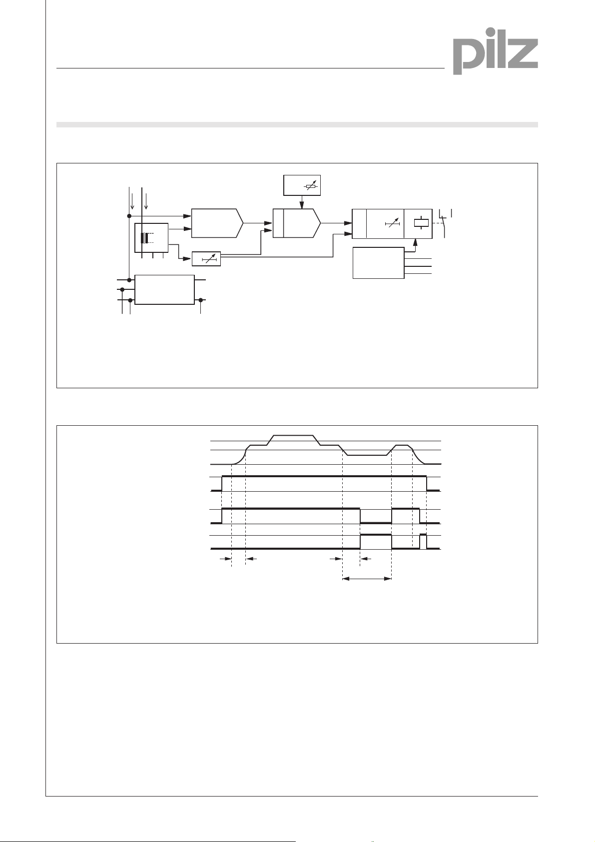
Internal wiring diagram
L1
k
I
I
M
M
U
L1
U
I
I
int
n*I
I
M
int
U(I)
Y1 Y2
L1
L2
L3
Power supply
cos j*k
L1 *
int
*
t
a
+
0
P
& &
P
min
P
min-PW
DP
min
t
r
Control logic
14
12
K1
11
Y3
Y4
Y5
4
W
V
I
Measuring currents
M
n Measuring range factor
U
L1
Measuring voltages
Timing diagram
Measuring circuit
Operating voltage U
Output P
min
Output P
min
B
(K1, RB)
(K1, AB)
RB Normally energised mode
AB Normally de-energised mode
P
Response value Underload
min
UL1Measuring voltage at L1
N
cos j Power factor
k Correction factor
Start-up suppression time
t
a
P
max
P
min
0
1
0
1
0
1
0
t
a
I
Measuring current
M
I
Internal measuring current
int
cos j Power factor
t
r
PW < P
k Correction factor
PWTrue power
P
Min. true power
min
t
Response delay
r
min
n Measuring range factor
t
Start-up suppression time
a
t
Response delay
r
Pilz GmbH & Co., Felix-Wankel-Straße 2, 73760 Ostfildern, Deutschland NSG-D-2-236-10/00
Telefon +49 (7 11) 34 09-0, Telefax +49 (7 11) 34 09-1 33, E-Mail: pilz.gmbh@pilz.de
Page 3

Electronic Monitoring Relays
True power monitoring
P1WU
Connection examples
● Example 1
Monitoring a three-phase motor, I < 5 A
L1
L2
L3
F1
L3L111 Y1 Y2 kN
L2
P1WU
Y4 Y512 14 Y3 U(I) V
W
K1
UVW
M1
M3~
£ 5 A
I
PE
N
● Example 2
Monitoring a three-phase motor(with current converter); I > 5 A
L1
L2
L3
F2
L3L111 Y1 Y2 kN
k K
T1
l L
W
P4B-3NK
P1WU
Y4 Y512 14 Y3
F1
L2
U(I) V
4
K1
UVW
M1
M3~
I > 5 A
PE
N
Pilz GmbH & Co., Felix-Wankel-Straße 2, 73760 Ostfildern, Deutschland NSG-D-2-236-10/00
Telefon +49 (7 11) 34 09-0, Telefax +49 (7 11) 34 09-1 33, E-Mail: pilz.gmbh@pilz.de
Page 4

Electronic Monitoring Relays
True power monitoring
P1WU
● Example 3
Monitoring a single-phase motor, I < 5 A
L1
N
F1
N
11 Y1
P1WU
12 14
Y2
Y3
Y4Y5U(I)
k
L1
L2 L3
VW
4
K1
M1
PE
● Example 4
Monitoring a single-phase motor; I > 5 A
L1
N
F1
11 Y1NY2
P1WU
Y3
12 14
k
Y4Y5U(I)
L1
L2 L3
VW
U1 U2
M 1~
I £ 5 A
N
F2
k K
T1
l L
K1
U1 U2
M1
M 1~
I ³ 5 A
PE
N
Pilz GmbH & Co., Felix-Wankel-Straße 2, 73760 Ostfildern, Deutschland NSG-D-2-236-10/00
Telefon +49 (7 11) 34 09-0, Telefax +49 (7 11) 34 09-1 33, E-Mail: pilz.gmbh@pilz.de
Page 5

Electronic Monitoring Relays
True power monitoring
P1WU
General Details
Unless stated otherwise in the technical details for the specific unit.
Electrical data
AC frequency range 50 ... 60 Hz
DC residual ripple 160 %
Contact material AgCdO
Continuous duty 100 %
Environmental data
EMC EN 50 081-1, 01/92; EN 50.082-2, 03/95
Vibration in accordance
with EN 60068-2-6, 04/95 Frequency: 10 ... 55 Hz,
Climatic suitability IEC 60068-2-3, 1969
Airgap creepage DIN VDE 0110-1, 04/97
Ambient temperature -10 ... +55 °C
Storage temperature -40 ... +85 °C
Mechanical data
Torque setting for connection terminals 0.6 Nm (screws)
Mounting position Any
Housing material Thermoplastic Noryl SE 100
Protection types Mounting: IP 54
Amplitude: 0.35 mm
Housing: IP 40
Terminals: IP 20
Order references key
U BSupply voltage
I MMeasuring current
taStart-up suppression time
trResponse delay
Order references
Type U
P1WU 110 VAC 5 A 20 s 3 s 489 103
P1WU 230 VAC 5 A 20 s 3 s 489 105
P1WU 400 VAC 5 A 20 s 3 s 489 110
P1WU 415 VAC 5 A 20 s 3 s 489 117
P1WU 460 VAC 5 A 20 s 3 s 489 118
P1WU 500 VAC 5 A 20 s 3 s 489 120
P1WU 230 VAC 5 A 20 s 30 s 489 132
P1WU 400 VAC 5 A 20 s 30 s 489 135
P1WU 415 VAC 5 A 20 s 30 s 489 140
P1WU 460 VAC 5 A 20 s 30 s 489 143
P1WU 500 VAC 5 A 20 s 30 s 489 145
P1WU 400 VAC 1 A 20 s 3 s 489 330
P1WU 500 VAC 1 A 20 s 3 s 489 335
B
I
M
t
a
t
r
Order no.
4
Pilz GmbH & Co., Felix-Wankel-Straße 2, 73760 Ostfildern, Deutschland NSG-D-2-236-10/00
Telefon +49 (7 11) 34 09-0, Telefax +49 (7 11) 34 09-1 33, E-Mail: pilz.gmbh@pilz.de
 Loading...