

Page 1
Electronic Monitoring Relays
True power monitoring
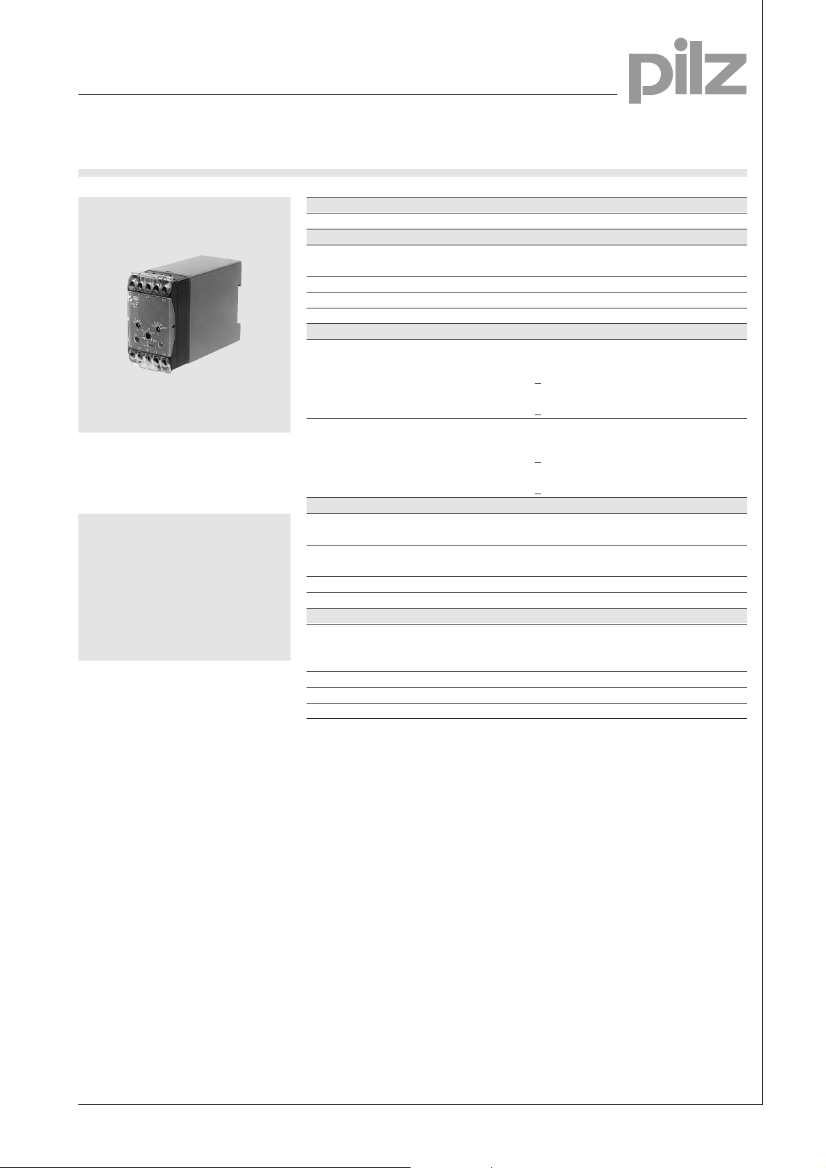
P1WP
Technical Details P1WP
Electrical data
Measuring voltage = Supply voltage 3 AC: 24, 42, 48, 110, 120, 230, 240,
Tolerance 85 ... 110 %
AC frequency range 50 ... 60 Hz
Power consumption Approx. 4 VA
Output circuit
Motor operation:
Output voltage
Terminating impedance > 1 kW
Output current DC: 0 ... 20 mA
Terminating impedance < 0.5 kW
Generator operation:
Output voltage
True power converter for 1 and
3-phase power supplies with
analogue true value output
Features
● Direct measurement of motors
with a 2.2 kW (400 V) rating
● Analogue output
● Suitable for current transformers
● Suitable for use with motors and
generators
Terminating impedance > 2 kW
Output current DC: 0 ... -10 mA
Terminating impedance < 0.5 kW
Measuring circuit
Adjustable measuring range limit values 1 A version: 0.2; 0.4; 0.6; 0.8; 1 A
Max. overload 1 A version: 1.2 A, 6 A/max. 3 s
Reaction time Approx. 200 ms
Start-up suppression time 0.5 ... 20 s adjustable
Mechanical data
Max. cable cross section 2 x 2.5 mm
of external conductor Single-core or multi-core with crimp
Torque setting for connection terminals 1.2 Nm (screws)
Dimensions (H x W x D) 75 x 45 x 110 mm
Weight 380 g
400, 415, 440, 460, 500 550 V
DC: 0 ... 10 V
DC: 0 ... -10 V
5 A version: 1; 2; 3; 4; 5 A
5 A version: 6 A, 25 A/max. 3 s
2
connector
4
Description
The true power converter is enclosed
in a P-75 housing. Three phase AC
voltage is required for operation.
Features:
● 2 versions, each with 5 adjustable
measuring ranges, up to max. 1 A
or up to max. 5 A
● Adjustable start-up suppression
time
● LED for supply voltage
Pilz GmbH & Co., Felix-Wankel-Straße 2, 73760 Ostfildern, Deutschland NSG-D-2-233-07/00
Telefon +49 (7 11) 34 09-0, Telefax +49 (7 11) 34 09-1 33, E-Mail: pilz.gmbh@pilz.de
The P1WP converts the true power
or the rated power used on a motor
or generator into an electrical output
signal which is proportional to the
true power. Measurement is
suppressed during the start-up
phase to avoid spurious output
signals. The start-up suppression
time ta can be set.
Page 2
Electronic Monitoring Relays
True power monitoring
P1WP
Block diagram
k1
L1 L2 L3
4
I
M
n*I
M
U/I1
I
Measuring current
M
n Measuring range factor
U Measuring voltage
cos j Power factor
Timing diagram
Generator operation
Power supply
10 V
20 mA
+
0
h
-
U
I
M
U*I
M
t
a
PWTrue power
h Efficiency
t
Start-up suppression time
a
"x"
U
A
I
A
cos j*k
*
U
P
W
&
A
I
U
A
P
A
P
W
I
U
A
N
I
A
UAOutput voltage
I
Output current
A
PAOutput power
P
max
W
Output voltage
U
A
I
Output current
A
-P
max
U
A
-10 mA
-20 V
P
Motor operation
Pilz GmbH & Co., Felix-Wankel-Straße 2, 73760 Ostfildern, Deutschland NSG-D-2-233-07/00
Telefon +49 (7 11) 34 09-0, Telefax +49 (7 11) 34 09-1 33, E-Mail: pilz.gmbh@pilz.de
Page 3

Electronic Monitoring Relays
True power monitoring
P1WP
Connection examples
● Example 1
Measuring a three phase motor, I < 5 A
L1
L2
L3
F1
U
B
L1
K1
P1WP
k U/I N ±U
UVW
M1
UBSupply voltage
I
Nominal current
N
PE
M 3~
I - 5 A
N
● Example 2
Measuring a three phase motor, I < 5 A (with current converter)
L1
L2
L3
F1
L3
L2
±I
A
V
4
U
B
L1
K1
P1WP
k U/I N ±U
T1
M1
K k
L l
UVW
M 3~
L3
L2
±I
A
V
UBSupply voltage
I - 5 A
I
Nominal current
N
PE
Pilz GmbH & Co., Felix-Wankel-Straße 2, 73760 Ostfildern, Deutschland NSG-D-2-233-07/00
Telefon +49 (7 11) 34 09-0, Telefax +49 (7 11) 34 09-1 33, E-Mail: pilz.gmbh@pilz.de
N
Page 4

Electronic Monitoring Relays
True power monitoring
P1WP
General Details
Unless stated otherwise in the technical details for the specific unit.
Electrical data
AC frequency range 50 ... 60 Hz
DC residual ripple 160 %
Contact material AgCdO
Continuous duty 100 %
Environmental data
EMC EN 50 081-1, 01/92; EN 50.082-2, 03/95
Vibration in accordance
with EN 60068-2-6, 04/95 Frequency: 10 ... 55 Hz,
Climatic suitability IEC 60068-2-3, 1969
Airgap creepage DIN VDE 0110-1, 04/97
Ambient temperature -10 ... +55 °C
Storage temperature -40 ... +85 °C
Mechanical data
Torque setting for connection terminals 0.6 Nm (screws)
Mounting position Any
Housing material Thermoplastic Noryl SE 100
Protection types Mounting: IP 54
Amplitude: 0.35 mm
Housing: IP 40
Terminals: IP 20
4
Order references key
UBSupply voltage
UMMeasuring voltage
IMMeasuring current
IAOutput current
Order references
Type U
P1WP 230 VAC 1 A 490 050
P1WP 230 VAC 5 A 490 150
P1WP 400 VAC 1 A 490 060
P1WP 400 VAC 1 A 4-20 mA 490 061
P1WP 400 VAC 5 A 490 160
P1WP 400 VAC 5 A 4-20 mA 490 161
P1WP 415 VAC 5 A 490 165
P1WP 440 VAC 1 A 490 062
P1WP 440 VAC 5 A 490 170
P1WP 460 VAC 5 A 490 175
P1WP 500 VAC 1 A 490 080
P1WP 500 VAC 1 A 4-20 mA 490 081
P1WP 500 VAC 5 A 490 180
P1WP 500 VAC 5 A 4-20 mA 490 184
P1WP 550 VAC 5 A 490 185
Additional versions available on request
B
I
M
I
A
Order no.
Pilz GmbH & Co., Felix-Wankel-Straße 2, 73760 Ostfildern, Deutschland NSG-D-2-233-07/00
Telefon +49 (7 11) 34 09-0, Telefax +49 (7 11) 34 09-1 33, E-Mail: pilz.gmbh@pilz.de
 Loading...