

Page 1
Electronic Monitoring Relays
True power monitoring
P1W
Technical Details P1W
Electrical data
Measuring voltage = Supply voltage 3 AC/1 AC: 42, 110, 230, 400, 415, 440,
Tolerance 85 ... 110 %
Power consumption Approx. 5 VA
Switching capability in accordance
with EN 60947-4-1, 10/91 AC1: 240 V/5 A/1200 VA
Output contacts 2 auxiliary contacts (C/O)
Contact fuse protection 6 A quick or 4 A slow
in accordance with EN 60947-5-1, 10/91
Max. switch-on current 10 A
Measuring circuit
Adjustable measuring range limit values 1 A version 0.125; 0.250; 0.375; 0.500;
True power monitor for 1- and
3-phase supplies for monitoring
minimum and maximum true power
values
Features
● Direct measurement of motors
with a 2.2 kW (400 V) rating
● Output signal either latching/
non-latching
● Short, adjustable reaction times
● High level of accuracy
● Operates to normally energised
or normally de-energised mode
● Suitable for current transformers
Max. overload 1 A version: 1.2 A; 6 A/max. 3 s
Response delay 1A version: 0,25 ... 3 s adjustable
Start-up suppression time 0.5 ... 20 s adjustable
Requirements for current transformer 1 A version: 1.5 ... 7.5 VA, Class 3
Mechanical data
Max. cross section of external conductor 2 x 2.5 mm
Torque setting for connection terminals 1.2 Nm (screws)
Dimensions (H x W x D) 75 x 90 x 115 mm
Weight 520 g
500, 550 V
DC1: 24 V/1 A/24 W
0.625 A; 0.750; 0.875; 1.0; 1.125 A
5 A version: 0.5; 1; 1.5; 2; 3; 4; 5; 6 A
5 A version: 6 A; 25 A/max. 3 s
5 A version: 1 ... 30 s adjustable
5 A version: 2.5 ... 15 VA, Class 3
2
Single-core or multi-core with crimp
connector
4
Description
The P1W monitors whether true
power falls below or exceeds a
The true power monitor is enclosed
in a 90 mm wide P-75 housing.
Single or three phase AC voltage is
required for operation.
Features:
● Relay outputs:
2 auxiliary contact (C/O)
● 2 versions with adjustable
measuring ranges up to
max. 1 A or up to max. 5 A
● Underload and overload
switching points
● Response delay for under- and
overload can be set separately.
● Adjustable start-up suppression
defined level on AC or 3-phase
current loads. The minimum and
maximum permitted true power
P
and P
min
potentiometers.
are set on separate
max
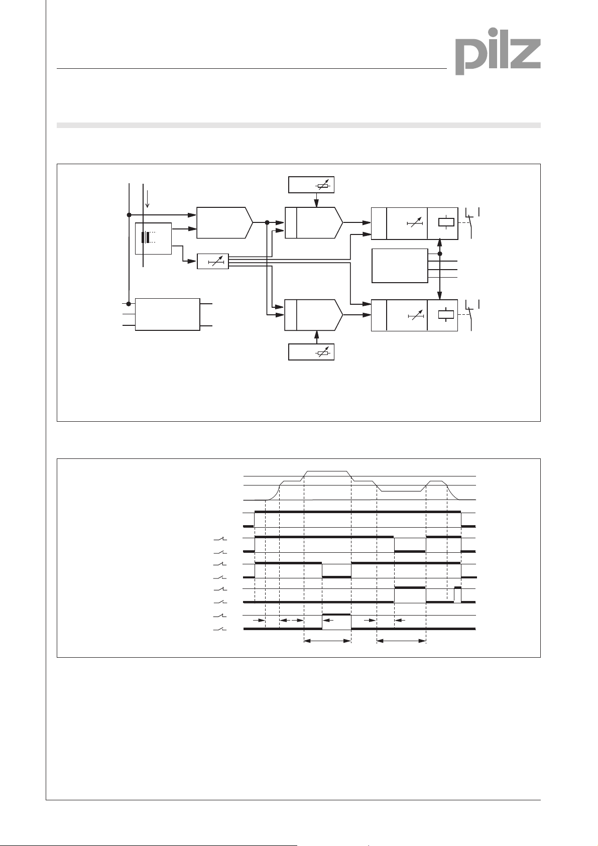
The P1W determines true power
from the phase voltage and the
measuring current. If the derived
true power exceeds the preset value
P
, the auxiliary contact assigned
max
to P
switches state and the LED
max
is on. If the derived true power falls
below the preset value P
auxiliary contact assigned to P
switches state and the LED is on.
min
, the
min
time
● Automatic or manual reset
● LEDs for supply voltage and
switching status of auxiliary
contacts P
Pilz GmbH & Co., Felix-Wankel-Straße 2, 73760 Ostfildern, Deutschland NSG-D-2-235-07/00
Telefon +49 (7 11) 34 09-0, Telefax +49 (7 11) 34 09-1 33, E-Mail: pilz.gmbh@pilz.de
and P
min
max
Page 2
Electronic Monitoring Relays
True power monitoring
P1W
Block diagram
k
L1
I
M
U
L1
U
I
I
int
n*I
M
I
int
U
L1
L2
L3
Power supply
cos j*k
L1
*
int
*
t
a
+
0
P
P
min
14
12
DP
DP
min
max
&
Control
logic
&
t
r,min
t
r,max
K1
11
Y1
N
Y2
24
22
K2
21
P
&
min-PW
&
P
max-PW
P
max
4
I
Measuring currents
M
n Measuring range factor
U
L1
cos j Power factor
Measuring voltages
Timing diagram
Measuring circuit
Meßkreis
Betriebsspannung
Supply voltage
Ausgang P
Output P
Ruhestromprinzip
Normally energised
Ausgang P
Output P
Ruhestromprinzip
Normally energised
Ausgang P
Output P
Arbeitsstromprinzip
Normally de-energised
Ausgang P
Output P
Arbeitstromprinzip
Normally de-energised
mode
max
mode
mode
max
mode
k Correction factor
Start-up suppression time
t
a
PWTrue power
P
max
P
min
0
U
U
B
11
min
max
11
21
max
21
11
min
max
11
21
max
21
B
0
14
12
24
22
14
12
24
22
t
a
t
r,max
PW > P
max
P
P
t
t
r,min
PW < P
Min. true power
min
Max. true power
max
Response delay
rmin, rmax
min
Pilz GmbH & Co., Felix-Wankel-Straße 2, 73760 Ostfildern, Deutschland NSG-D-2-235-07/00
Telefon +49 (7 11) 34 09-0, Telefax +49 (7 11) 34 09-1 33, E-Mail: pilz.gmbh@pilz.de
Page 3

Electronic Monitoring Relays
True power monitoring
P1W
Connection examples
● Example 1
Monitoring a three-phase motor, I < 5 A
L1
L2
L3
F2
I
Nominal current
N
PE
11 21
P1W
12 14
N
22
k
Y1
L1
24 U N
● Example 2
Monitoring a three-phase motor; I > 5 A
L1
L2
L3
F1
L2 L3
Y2
K1
UVW
M1
I ≤ 5 A
N
M3~
4
F2
I
Nominal current
N
PE
P1W
12 14
21 Y1
22 U
kN
24
L3L111
L2
k K
T1
l L
Y2N
K1
UVW
M1
I > 5 A
N
M3~
Pilz GmbH & Co., Felix-Wankel-Straße 2, 73760 Ostfildern, Deutschland NSG-D-2-235-07/00
Telefon +49 (7 11) 34 09-0, Telefax +49 (7 11) 34 09-1 33, E-Mail: pilz.gmbh@pilz.de
Page 4

Electronic Monitoring Relays
True power monitoring
P1W
● Example 3
Monitoring a single-phase motor, I < 5 A
L1
N
F1
L2
L3L111 21 Y1 kN
P1W
2412 14 22 U
Y2N
4
K1
M1
I ≤ 5 A
N
PE
I
Nominal current
N
● Example 4
Monitoring a single-phase motor; I > 5 A
L1
N
F1
P1W
12 14
21 Y1
22 U
kN
24
U1 U2
M 1~
L2
F2
L3L111
k K
T1
l L
Y2N
K1
U1 U2
M1
M 1~
N
Nominal current
I
N
I ≥ 5 A
PE
Pilz GmbH & Co., Felix-Wankel-Straße 2, 73760 Ostfildern, Deutschland NSG-D-2-235-07/00
Telefon +49 (7 11) 34 09-0, Telefax +49 (7 11) 34 09-1 33, E-Mail: pilz.gmbh@pilz.de
Page 5

Electronic Monitoring Relays
True power monitoring
P1W
General Details
Unless stated otherwise in the technical details for the specific unit.
Electrical data
AC frequency range 50 ... 60 Hz
DC residual ripple 160 %
Contact material AgCdO
Continuous duty 100 %
Environmental data
EMC EN 50 081-1, 01/92; EN 50.082-2, 03/95
Vibration in accordance with
EN 60068-2-6, 04/95 Frequency: 10 ... 55 Hz,
Climatic suitability IEC 60068-2-3, 1969
Airgap creepage DIN VDE 0110-1, 04/97
Ambient temperature -10 ... +55 °C
Storage temperature -40 ... +85 °C
Mechanical data
Torque setting for connection terminals 0.6 Nm (screws)
Mounting position Any
Housing material Thermoplastic Noryl SE 100
Protection types Mounting: IP 54
Amplitude: 0.35 mm
Housing: IP 40
Terminals: IP 20
Order references key
UBSupply voltage
IMMeasuring current
taStart-up suppression time
trResponse delay
Order references
Type U
P1W 110 VAC 5 A 20 s 3 s 489 515
P1W 230 VAC 5 A 20 s 3 s 489 520
P1W 400 VAC 5 A 20 s 3 s 489 525
P1W 415 VAC 5 A 20 s 3 s 489 530
P1W 440 VAC 5 A 20 s 3 s 489 533
P1W 500 VAC 5 A 20 s 3 s 489 540
P1W 550 VAC 5 A 20 s 3 s 489 545
P1W 230 VAC 1 A 20 s 3 s 489 720
P1W 400 VAC 1 A 20 s 3 s 489 725
P1W 415 VAC 1 A 20 s 3 s 489 730
P1W 500 VAC 1 A 20 s 3 s 489 740
P1W 42 VAC 5 A 20 s 30 s 489 605
P1W 230 VAC 5 A 20 s 30 s 489 620
P1W 400 VAC 5 A 20 s 30 s 489 625
P1W 415 VAC 5 A 20 s 30 s 489 630
P1W 440 VAC 5 A 20 s 30 s 489 633
P1W 500 VAC 5 A 20 s 30 s 489 640
P1W 230 VAC 1 A 20 s 30 s 489 745
P1W 400 VAC 1 A 20 s 30 s 489 825
P1W 440 VAC 1 A 20 s 30 s 489 733
P1W 500 VAC 1 A 20 s 30 s 489 845
Additional versions available on request
B
I
M
t
a
t
r
Order no.
4
Pilz GmbH & Co., Felix-Wankel-Straße 2, 73760 Ostfildern, Deutschland NSG-D-2-235-07/00
Telefon +49 (7 11) 34 09-0, Telefax +49 (7 11) 34 09-1 33, E-Mail: pilz.gmbh@pilz.de
 Loading...