Physiomed PHYSIOTHERM-S User manual

S E R V I C E M A N U A L
PHYSIOTHERM-S
Revision: 09 / 2008
Table of Contents
1 GENERAL |
3 |
||
1.1 |
Packaging / Transport |
4 |
|
1.1.1 |
Transporting the Unit |
4 |
|
1.1.2 |
Unpacking the Unit |
4 |
|
1.1.3 |
Packing the Unit |
4 |
|
1.2 |
Notes on Safety |
5 |
|
1.3 |
Service Principle |
5 |
|
2 TECHNICAL DESCRIPTION |
6 |
|
2.1 |
Technical Data |
6 |
2.2 |
Circuit Description |
7 |
2.3 |
Power Supply with PCB Input |
7 |
2.4 |
PCB Power Supply |
7 |
2.4.1 Power Setting – PCB Power Supply |
9 |
|
2.5 |
HF Signal Generator |
10 |
2.6 |
Preliminary Amplifier |
10 |
2.7 |
Power Amplifier |
10 |
2.8 |
Output Circuit |
11 |
2.9 |
Operating Panel |
11 |
3 MOUNTING AND DISMOUNTING ELEMENTS AND PARTS |
12 |
|
3.1 |
Elements |
12 |
3.2 |
Spare Parts |
13 |
3.3 |
Opening and Closing the Unit |
15 |
3.4 |
Exchanging PCB Controller, Display and Key Pad |
16 |
3.5 |
Exchanging the Signal Generator and the Preliminary Amplifier |
16 |
3.6 |
Exchanging the Power Amplifier |
17 |
3.7 |
Exchanging the Output Circuit |
17 |
3.8 |
Exchanging the Tuning Element |
18 |
3.9 |
Exchanging the Power Switch |
18 |
3.10 |
Exchanging the Power Supply |
18 |
3.11 |
Exchanging the Anode/Control Transformer |
19 |
4 |
SERVICE SETTINGS AND CHECKS |
21 |
|
|
4.1 |
The Service Menu |
21 |
|
4.1.1 Activating the Service Menu |
21 |
|
|
4.2 |
Manufacturer recommendations on safety inspections according to 93/42 EEC |
22 |
|
4.3 |
Visual Inspections and Function Checks |
22 |
|
4.4 |
Setting the Output Power (PCB power supply) |
23 |
|
4.5 |
Setting the Voltage of the Input Circuit |
24 |
5 |
ERROR DIAGNOSIS PHYSIOTHERM-S |
25 |
|

General
1 General
With PHYSIOTHERM-S you have acquired a high-quality and extremely versatile unit for short wave therapy. The most remarkable features of PHYSIOTHERM-S are its convenient operation and modern design as well as its easy maintenance and servicing and high degree of reliability.
The integrated safety functions for improving patient safety more than fulfill legal requirements. The unit is CE-labelled and thus meets the basic requirements laid down in the EC regulations for medical products.
Please note that this Service Manual was established on the basis of the Operating Instructions. Important notes on handling and operating the unit are contained in the Operating Instructions.
If your PHYSIOTHERM-S is in need of service, please contact:
PHYSIOMED ELEKTROMEDIZIN AG
Hutweide 10
D-91220 Schnaittach / Laipersdorf (Germany)
Phone +49 (0) 9126 2587-0
Fax +49 (0) 9126 2587-25
In case of technical problems or if you have technical questions, please contact your local distributor or the address mentioned above.
The unit may only be maintained by PHYSIOMED ELEKTROMEDIZIN AG or an authorized dealer.
If you ever need to return the unit to your dealer or to PHYSIOMED ELEKTROMEDIZIN AG, the original packaging needs to be used. The following information needs to be included:
•owner's name and address
•serial and device number
•description of the error (including error code)
PHYSIOTHERM-S- Service Manual |
3 |

General
1.1 Packaging / Transport
1.1.1Transporting the Unit
In order to ensure save transportation of PHYSIOTHERM-S, the original packaging should be used for transportation. This particular packaging offers the protection required for the transport of the unit in an upright position. Protection is not ensured for flat transportation, which may result in the unit being damaged and impaired in its function.
The authorized dealer or the owner is responsible for proper packaging and needs to ensure that all safety and accident prevention requirements are met.
1.1.2Unpacking the Unit
The unit is generally delivered with the packaging material supplied by the manufacturer. Since the unit's weight is about 60 kg, it must be unpacked by at least two people!
Proceed as follows:
•Position the transport packaging so that the UP mark is pointing upward.
•Remove the safety straps from the transport packaging.
•Lift the upper part of the transport packaging and remove it from the unit.
•Remove the top part of the foam material.
•Lift (at least two people) the unit from the lower part of the packaging.
1.1.3Packing the Unit
The unit should always be transported in its original packaging. Since the unit's weight is about 60 kg, it must be packed by at least two people!
Proceed as follows:
•Bend down both electrode arms.
•Affix the lower part of the transport packaging to the pallet.
•Place the bottom part of the foam material into the lower part of the transport packaging, the square cut-out facing up.
•Put the unit into the square cut-out (at least two people are required!) of the bottom part of the foam material.
•Pack all accessories separately. They may be placed in the space left by the unit (between the case and the operating panel) and shipped within the transport packaging.
•Place the protective cover (if available) over the unit.
•Now place the top part of the foam material over the unit.
•Put the upper part of the transport packaging over the unit packed in the foam material and slide it over the lower part of the packaging.
•Secure the complete packaging (upper + lower part of packaging + pallet) with safety straps.
4 |
PHYSIOTHERM-S - Service Manual |

General
1.2 Notes on Safety
Some parts within the unit are directly connected to the electric supply system. For some service work it may be required to operate PHYSIOTHERM-S while the unit is open and conduct measurements and settings. For this purpose, the usual safety regulations for preventing electric shock need to be observed.
During operation, voltages of up to several thousand volts are produced in the electric wiring system and the high frequency generator. In particular, the high-voltage supply unit, the tube power amplifier and the transformers may carry currents against electric earth that could result in electric shock.
For use of this Service Manual, knowledge of the Operating Instructions is required.
1.3 Service Principle
PHYSIOTHERM-S is of a modular design. All parts can be mounted and dismounted quickly. Electric and electronic modules are plugged in so that no soldering is required. In case an error occurs on a board or a module it will be replaced for a replacement charge, since repair of a board is usually not practicable on site. Repair is carried out at the manufacturer, if feasible. For this reason, no circuit diagrams of the modules are included in this Service Manual.
PHYSIOTHERM-S- Service Manual |
5 |

Technical Description
2 Technical Description
2.1 Technical Data
Mains connection |
115 V / 230 V; 50-60 Hz |
|
|
|
set by voltage selector (anode and control transformer) |
||
|
within the unit |
|
|
Power line input |
without HF output |
|
approx. 200 VA |
|
with maximum output |
approx. 1400 VA |
|
Line fuse (unit) |
16 A (115V) |
8 A (230V) |
|
Protection class |
I |
|
|
Class acc. to EC 93/42 |
IIa |
|
|
Type |
BF |
|
|
HF nominal power |
1000 W pulsed mode (at pulse peak) |
||
|
400 W continuous mode |
|
|
Power setting |
10 W increments (CW mode) |
||
|
50 W increments (pulsed mode) |
||
Power indication |
Amplitude and effective power |
||
Working frequency |
27.12 MHz +/- 0.6 % |
|
|
Pulse duration |
200 - 600 μs |
|
|
Pulse frequency |
10 - 300 Hz |
|
|
Treatment duration |
1 - 60 min |
|
|
Design |
IEC 601-1, IEC 601-2-3, IEC 601-1-2 |
||
Weight |
approx. 60 kg |
|
|
Dimensions in mm |
420 x 970 x 405 (W x H x D) |
|
|
|
conforms to European Council Directive concerning medical |
||
|
devices 93/42 EEC |
|
|
6 |
PHYSIOTHERM-S - Service Manual |

Technical Description
2.2 Circuit Description
The electric components of PHYSIOTHERM-S are located beneath the covering plate (operating panel) and on the boards for power supply; preliminary amplifier and signal generator are located behind the casing cover. The boards and all other electric components are connected via a plug connection and flat strip wires. The following functional blocks may be distinguished according to the block diagram on the following page.
2.3 Power Supply with PCB Input
Power is supplied via the mains supply. The supply voltage is directed to the power switch on the left side of the unit via the PCB input (X1).
Power is supplied via the PCB input to the no-heating appliance plug, the power switch and the anode and control transformers.
The voltage selectors for 115 V or 230 V operation are placed in sockets X10 and X3.
Current limitation control transformer: via NTC resistor R12
Current limitation anode transformer: via resistor R1/R2 and relay K1. After current limitation, the resistors are bridged by the switching contacts of relay K1. The LED V3 indicates that the relay K1 has been activated.
Switching anode voltage: via the relay K2 on the primary side of the anode transformer. The LED V4 indicates that the relay K2 has been activated. The relay is controlled by the power supply via the terminal X9.
The anode transformer is connected to the terminals X7 and X8. The thermal switches of the anode and control transformers are connected to the terminals X7 and X8.
2.4 PCB Power Supply
The high voltage generated by the anode transformer is supplied via the terminals X3 and X5.
In the lower range of performance (up to 280 W), the voltage amounts to 700 V AC, and to 1000 V AC in the upper range of performance (above 280 W).
High voltage is rectified, smoothed and increased by the factor 2.5.
Rectified high voltage in the lower range of performance: approx. 1,750 V DC (700 V x 2.5)
Rectified high voltage in the upper range of performance: approx. 2,500 V DC (1,000 V x 2.5)
The PCB power supply generates the grid voltage required for setting the operating point of the tube.
PHYSIOTHERM-S- Service Manual |
7 |

Technical Description
The PCB power supply also generates the rectified and stabilised supply voltages of 5 V, +/- 15 V, + 24 V and the unstabilised voltage of 50 V. These voltages are required for operating the individual modules.
Supply voltages at terminal strip X4 (HF power output 0 Watt / cont.)
Pin |
Measuring point |
LED |
Voltage |
(terminal strip) |
|
|
|
|
|
|
|
1 |
MPP5VDC-A |
- |
4.8 V-5.2 V |
|
|
|
|
2 |
MPP5VDC-AS |
- |
4.8 V-5.2 V |
|
|
|
|
3 |
MPP5VDC-B |
B3 |
4.8 V-5.2 V |
|
|
|
|
4 |
MPP15VDC |
B4 |
14.4 V-15.6 V |
|
|
|
|
5 |
MPM15VDC |
B5 |
-14.4 V-(-15.6 V) |
|
|
|
|
6 |
MPP24VDC |
B4 |
23 V-25 V |
|
|
|
|
7 |
Earth |
- |
0 V |
|
|
|
|
8 |
free |
- |
- |
|
|
|
|
9 |
MPP50VDC |
B4 |
49 V-55 V |
|
|
|
|
10 |
Earth |
- |
0 V |
|
|
|
|
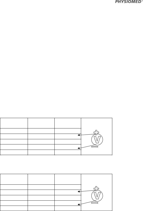
Grid current measuring point at terminal strip X1 (HF power output 400 Watt / cont.)
Pin |
Measuring point |
Voltage |
(terminal strip) |
|
|
1 |
Earth |
0 V |
2 |
MPIG-A |
0-100 mV |
3 |
free |
- |
4 |
MPIG-B |
0-100 mV |
5 |
Earth |
0 V |
Measured with voltmeter between PIN2 and PIN4 (1 mV corresponds to 1 mA)
Anode current measuring point at terminal strip X2 (HF power output 400 Watt / cont.)
Pin |
Measuring point |
Voltage |
(terminal strip) |
|
|
1 |
Earth |
0 V |
2 |
MPIA-A |
0-400 mV |
3 |
free |
------- |
4 |
MPIA-B |
0-400 mV |
5 |
Earth |
0V |
Measured with voltmeter between PIN2 and PIN4 (1 mV corresponds to 1 mA)
8 |
PHYSIOTHERM-S - Service Manual |
 Loading...