


 Loading...
O P E R A T I N G I N S T R U C T I O N S
PHYSIOMED-Expert
00856 GB
The technical data in this manual is as at the time of printing and subject to alteration.
Copyright © 2000 - 2010 by PHYSIOMED Elektromedizin AG
All rights, including rights of translation, reproduction by printing, copying or similar methods, even of parts are reserved.
Offenders will be liable for damages.
Last updated August 30, 2010.
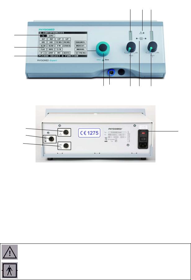
Instrument Overview
Front Panel |
7 |
11 |
9 |
|
2
3
4
5 |
12 |
6 |
10 |
|
8 |
|
|
|
|
|
|
Rear Face
14
1
13
15
Legend
1 |
Mains Module |
6 |
Intensity Control Circuit I |
11 |
Output Indicator |
2 |
Upper Status Bar |
7 |
Pulse Indicator Circuit I |
12 |
Patient Lead Connector |
3 |
Display |
8 |
Intensity Control Circuit II |
13 |
Manual Release Key or |
|
|
|
|
|
Therapy Pause Button |
|
|
|
|
|
Socket |
4 |
Lower Status Bar |
9 |
Pulse Indicator Circuit II |
14 |
SIM Socket |
5 |
Data Selector |
10 |
Patient Current Indicator |
15 |
VAC Socket |
|
|
|
|
|
|
Symbols
CAUTION!
Please refer to the operating instructions and consider the physiological effects!
Type BF component, not connected to protective ground wire!
Contents
1 |
Introduction...................................................................................................................... |
1 |
1.1 |
Instrument Description................................................................................................................ |
1 |
1.2 |
Application ................................................................................................................................... |
1 |
1.3 |
Contraindications ......................................................................................................................... |
2 |
2 Controls and Indicators.................................................................................................... |
3 |
|
2.1 Function of Controls and Indicators ........................................................................................... |
3 |
|
2.1.1 |
Mains Module <1>...................................................................................................................... |
3 |
2.1.2 |
Upper Status Bar<2> ................................................................................................................... |
4 |
2.1.3 |
Display <3> ................................................................................................................................. |
4 |
2.1.4 |
Lower Status Bar<4> ................................................................................................................... |
4 |
2.1.5 |
Data Selector <5>........................................................................................................................ |
4 |
2.1.6 |
Intensity Control Circuit I <6>...................................................................................................... |
5 |
2.1.7 |
Pulse Indicator Circuit I <7>......................................................................................................... |
5 |
2.1.8 |
Intensity Control Circuit II <8>..................................................................................................... |
6 |
2.1.9 |
Pulse Indicator Circuit II <9> ........................................................................................................ |
6 |
2.1.10 |
Patient Current Indicator <10> .................................................................................................... |
7 |
2.1.11 |
Output Indicator <11> ................................................................................................................ |
7 |
2.1.12 |
Patient Lead Connector <12>...................................................................................................... |
7 |
2.1.13 |
Manual Release Key Socket <13> ................................................................................................ |
8 |
2.1.14 |
SIM Socket<14>.......................................................................................................................... |
8 |
2.1.15 |
VAC Socket <15>........................................................................................................................ |
8 |
2.2 |
Overview of Parameters.............................................................................................................. |
9 |
2.2.1 |
Start Menu (1st level).................................................................................................................... |
9 |
2.2.2 |
Example Menu (2nd level) ............................................................................................................. |
9 |
2.3 |
Operation................................................................................................................................... |
10 |
2.3.1 |
Parameters for Circuit I ............................................................................................................. |
10 |
2.3.2 |
Parameters for i/t-diagnostics.................................................................................................... |
14 |
2.3.3 |
Dual channel operation ............................................................................................................ |
14 |
2.4 Characterisation of the Individual Current Modes................................................................. |
19 |
|
2.4.1 |
Low-frequency Current Modes (LF)........................................................................................... |
19 |
2.4.2 |
Medium-Frequency Currents .................................................................................................... |
28 |
2.4.3 |
Current Modes of the Diagnostics Menu .................................................................................. |
30 |
3 |
Notes on Operation ....................................................................................................... |
31 |
3.1 |
Connection and Start-up .......................................................................................................... |
31 |
3.2 |
Device Start-up.......................................................................................................................... |
31 |
3.3 |
Self-test routine ........................................................................................................................ |
31 |
3.4 |
Instrument Errors ...................................................................................................................... |
32 |
4 Stimulation Current Therapy......................................................................................... |
33 |
|
4.1 |
General Information ................................................................................................................. |
33 |
4.2 |
Safety Precautions when Attaching Electrodes ..................................................................... |
33 |
4.3 |
Safety Precautions for Stimulation Current Intensity............................................................ |
34 |
4.3.1 |
Recommended Intensities ......................................................................................................... |
34 |
4.4 |
Preparations and Attaching the Electrodes ............................................................................ |
35 |
4.4.1 |
Modes of attaching the electrodes ........................................................................................... |
35 |
4.5 |
Therapy using low-frequency current modes ........................................................................ |
36 |
4.5.1 |
Monophase and biphase current modes ................................................................................... |
36 |
4.5.2 |
Iontophoresis............................................................................................................................ |
36 |
4.5.3 |
Pain Therapy, Hyperaemisation, Detonisation ........................................................................... |
37 |
4.5.4 |
Muscle Stimulation using Low-Frequency Currents ................................................................... |
38 |
4.6 |
Therapy using medium-frequency current modes ................................................................. |
41 |
4.6.1 Therapy using classic interference current IF:: ........................................................................... |
41 |
|
4.6.2 Pain Therapy, Hyperaemisation, Detonisation using AMF Current ............................................. |
42 |
|
4.6.3 Muscle Stimulation using Medium-frequency Surge Currents ................................................... |
42 |
|
5 Diagnosis using Stimulation Current............................................................................ |
45 |
|
5.1 |
Faradic Excitability Test ............................................................................................................ |
45 |
5.2 Medium-frequency Test according to Lange .......................................................................... |
46 |
|
5.3 |
Accommodation Quotient........................................................................................................ |
46 |
5.4 |
Rheobase / Chronaxy................................................................................................................ |
47 |
5.5 |
I/T-Curve Diagnosis................................................................................................................... |
49 |
5.5.1 Procedure in Tabular Form........................................................................................................ |
49 |
|
5.5.2 Procedure in chart form............................................................................................................ |
50 |
|
5.5.3 Saving the i/t-Curve Diagnosis .................................................................................................. |
52 |
|
5.5.4 Recalling Stored i/t-Curve Measurements.................................................................................. |
52 |
|
5.5.5 Deleting Stored i/t-Curve Measurements .................................................................................. |
52 |
|
6 |
Simultaneous Therapy ................................................................................................... |
53 |
7 |
Indications Menu............................................................................................................ |
54 |
7.1.1 Spasticity treatment according to Hufschmidt / Jantsch (Tonolysis)............................................ |
55 |
|
8 |
Individual Programs ....................................................................................................... |
58 |
8.1 Save individual therapy modes ............................................................................................... |
58 |
|
8.2 |
Save Potpourri........................................................................................................................... |
59 |
8.3 |
Call Program .............................................................................................................................. |
60 |
8.4 |
Delete program ......................................................................................................................... |
60 |
9 |
Basic Settings.................................................................................................................. |
61 |
9.1 |
Setup Menu ............................................................................................................................... |
62 |
10 |
General Notes................................................................................................................. |
63 |
11 |
Service, Repairs, Maintenance ...................................................................................... |
63 |
12 |
Cleaning and Disinfection ............................................................................................. |
64 |
13 |
Connecting other Units.................................................................................................. |
64 |
13.1 |
Vacuum Unit .......................................................................................................................... |
64 |
13.2 |
Ultrasound Therapy Unit ...................................................................................................... |
64 |
14 |
Technical Data ................................................................................................................ |
65 |
15 |
Accessories...................................................................................................................... |
66 |
15.1 |
Standard Accessories ............................................................................................................ |
66 |
15.2 |
Additional Accessories .......................................................................................................... |
67 |
16 |
Manufacturer’s Recommendations............................................................................... |
70 |
17 |
Index ............................................................................................................................... |
71 |

Introduction
1Introduction
With your PHYSIOMED-Expert, you have acquired a high-quality and extremely versatile unit for stimulation current therapy.
The instrument will only show its true potential, however, if you are well informed about its functions. For this reason, carefully read the Operating Instructions and familiarise yourself with the use of the instrument.
1.1Instrument Description
PHYSIOMED-Expert is a two-channel stimulation current therapy unit. You can apply the whole range of current modes from low to medium frequency including the classic interference current. Moreover, the unit offers you programs for stimulation current diagnosis. The unit can also be used for simultaneous therapy (stimulation current and ultrasound in ONE treatment, page 53).
Therapy modes of PHYSIOMED-Expert may be accessed directly or, by a proposed treatment, via the indications menu (page 54). Moreover, the unit enables you to memorise up to 25 individual treatment programs or current sequences (potpourris, page 58).
All functions of PHYSIOMED-Expert are controlled by a microprocessor, which also continuously monitors all important components and suppresses erroneously initiated operating steps. After switching on, all instrument functions are checked during an automatic self-test routine. The instrument complies with all current safety standards.
The instrument meets the requirements of the EC directive concerning medical devices (93/42/EEC) and is therefore CE-labelled.
1.2Application
PHYSIOMED-Expert was designed for the following applications:
Stimulation current therapy
•Pain therapy
•Circulatory stimulation
•Mobilisation and muscle stimulation
•Spacticity treatment according to Hufschmidt and Jantsch
•Iontophoresis
Stimulation current diagnosis
•Faradic excitability test
•Medium-frequency test according to Lange
•Accommodation quotient
•Rheobase/chronaxy
•I/T-diagnosis
PHYSIOMED-Expert |
1 |
Introduction
Simultaneous therapy
•Simultaneous application of stimulation current and ultrasound
Warning The instrument may only be operated by qualified personnel who have undergone special training!
1.3Contraindications
Contraindications to stimulation current therapy or simultaneous treatment:
•Highly inflammatory, fever-prone disorders
•Pregnancy
•Patients with cardiac pacemakers or other implanted stimulators
•Malignant tumours
•Skin lesions
•Implants containing metal parts within the area of treatment
Contraindications to ultrasound therapy or simultaneous treatment:
•Fever-prone disorders and acute inflammatory processes
•Pregnancy
•Tuberculosis, gastric ulcers
•Vascular disorders of the extremities (thrombophlebitis, thrombosis, varicosis)
•Tumours
•Circulatory insufficiency, coronary diseases, cardiac dysrhythmias
•Acute articular rheumatism
•Diabetes mellitus
•Septic inflammations
•Conditions following radiothorium treatments, X-ray therapy
•Conditions following laminectomy
•Skin lesions (infections, inflammatory processes, naevi)
•Tumescences at all stages (pre-/postoperative)
•Blood coagulation diseases.
Do not apply ultrasound or simultaneous therapy close to the brain, spinal cord and eyes!
2 |
PHYSIOMED-Expert |
Controls and Indicators
2Controls and Indicators
As its LCD is divided in different function fields, PHYSIOMED-Expert allows for clear and easy operation.
The plastic housing and the front panel protect the electronic components and simplify cleaning.
Safety-related components are continuously monitored by the microprocessor, erroneously initiated operating steps are suppressed, a self-test routine is performed after switching on and possible malfunctions are displayed. For safety reasons, the stimulation current output is automatically cut off in case of malfunction.
2.1Function of Controls and Indicators
In the following section we will introduce the individual controls of PHYSIOMEDExpert. The numbers in angle brackets refer to the Instrument Overview at the beginning of this manual.
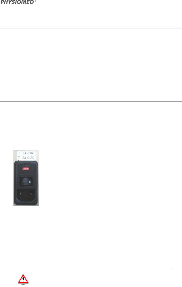
2.1.1 Mains Module <1>
The mains module <1> with mains supply, fuses and mains switch is situated at the rear side of the instrument.
For mains supply do only use the mains cable provided by the manufacturer.
PHYSIOMED-Expert is switched on and off using the integrated mains switch. After switching on, a self-test is automatically carried out by the instrument (cf. Notes on Operation on page 26).
Set the Line Voltage
After replacing the fuses, you can run the instrument with 230 V as well as 115 V simply by using the rotatable fuse carrier at the mains module <1> (refer to section Technical Data on page 56). The fuses are situated under the cover of the mains module <1> in a fuse carrier.
Replace 1 A fuses with 2 A fuses, turn the fuse carrier by 180° and insert it again, so that the “red window” of the mains module <1> reads “115 V”, after the cover has been closed again.
Warning Do run the instrument only with the indicated line voltage!
PHYSIOMED-Expert |
3 |
Controls and Indicators
2.1.2 Upper Status Bar<2>
The upper status bar <2> shows indications or some of the corresponding parameters selected. For example:  .
.
2.1.3 Display <3>
upper status bar
display
lower status bar
On the display <3>, you can select all of the instrument’s menus and parameters on different levels except for the intensity. The selection is carried out with the data selector <5>.
2.1.4 Lower Status Bar<4>
In the lower status bar<4>, messages and prompts are issued, e.g.:
 .
.
Use the data selector <5> to select the therapy parameters and to operate the instrument by means of the cursor. After switching on the instrument, the cursor is located at the current mode G of the display <3>.
You can move the cursor to the other menu items by turning the selector to the right or left. To select a menu, simply press the selector.
To select a parameter, move the cursor to the respective field by turning the selector. After pressing the selector, the cursor will start flashing. You will then be able to select the parameters by turning the selector and confirm the selected value by pressing the selector again (cursor stops flashing). The modified values are displayed in the upper status bar <2> or at the respective position of the display <3>.
4 |
PHYSIOMED-Expert |
Controls and Indicators
2.1.6 Intensity Control Circuit I <6>
The intensity control circuit I <6> serves to set the intensity in circuit I in steps of 0.5 mA. When turning up the intensity of intensity control circuit I <6> or intensity control circuit II <8>, the associated therapy timer in the display <3> will be started as well.
Whenever you have to turn down the intensity control circuit I to “0”, the following turn-down signal is displayed in the lower status bar <4>:
Automatic output current switch-off
PHYSIOMED-Expert disposes of an automatic output current switch-off activated in case the current flow of the electrodes is interrupted (electrode falls off, plug is disconnected from patient lead etc.). The message CHECK ELECTRODES I will appear in the lower status bar<4> and the current will be automatically turned down to a minimum basic current in circuit I. After eliminating the error, the current in circuit I will automatically be surged to the previously set value and the message will disappear.
2.1.7 Pulse Indicator Circuit I <7>
The pulse indicator circuit I <7> serves to visually monitor the current modes and intensities of circuit I. It flashes whenever a pulse is generated in circuit I by the processor, even in case of 0 intensity. It will stop flashing however when the intensity is automatically reduced by the therapy timer. After turning down the intensity of circuit I to 0 with the intensity control circuit I <6> the indicator will start flashing again. When changing the polarity of monophase currents in circuit I (display <3>) the indicator will show how the intensity increases or decreases automatically.
PHYSIOMED-Expert |
5 |
Controls and Indicators
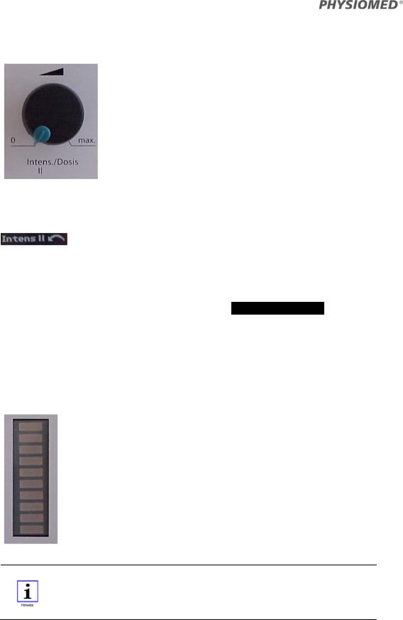
2.1.8 Intensity Control Circuit II <8>
The intensity control circuit II <8> serves to set the current intensity in circuit II in steps of 0.5 mA. When turning up one of the two intensity controls circuit I <6> or circuit II <8>, the associated therapy timer on the display <3> will be started as well.
Every time you have to turn down the intensity control circuit II to 0, the following message will be displayed in the lower status bar<4>:
Automatic output current switch-off
PHYSIOMED-Expert disposes of an automatic output current switch-off activated in case the current flow of the electrodes is interrupted (electrode falls off, plug is disconnected from patient lead etc.). The message CHECK ELECTRODES II will appear in the lower status bar<4> and the current will be automatically turned down to a minimum basic current in circuit II. After eliminating the error, the current in circuit II will automatically be turned up to the previously set value and the message will disappear.
2.1.9 Pulse Indicator Circuit II <9>
The pulse indicator circuit II <9> serves to visually monitor the current modes and intensities of circuit II. It flashes whenever an pulse is generated in circuit I by the processor, even in case of 0 intensity. It will stop flashing, however, when the intensity is automatically reduced by the therapy timer. After turning down the intensity of circuit I to zero with the intensity control circuit II <8>, the indicator will start flashing again.
Note Due to safety reasons increasing the ultrasound dose after the ultrasound has coupled (marker appears in the upper status bar <2>) is only possible after prior turning down the dose with intensity control circuit II/dose <8>.
6 |
PHYSIOMED-Expert |
Controls and Indicators
2.1.10 Patient Current Indicator <10>
The diode at the left side of the symbol is attributed to circuit I, the diode at the right to circuit II. The flashing of the indicators depends on the resistance in the two circuits.
In most cases the diodes start flashing exactly at the moment when the patient starts to have a clear sensation of the current in the corresponding circuit.
If the indicator does not flash during treatment, you have to carry out a self-test routine and observe whether or not the indicator flashes. If the indicator still does not flash during treatment after the check, the accessories of the corresponding circuit should be checked and replaced if necessary.
2.1.11 Output Indicator <11>
The indicator tells you to be cautious when handling the electrodes:
Warning! The patient lead connector <12> is under voltage! Take care that the electrodes are by no means touched after the current is turned up!
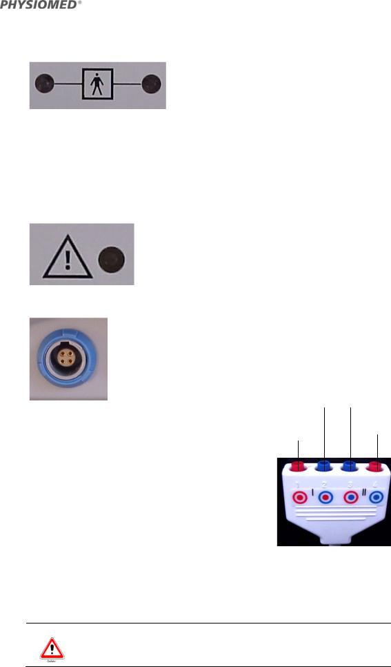
2.1.12 Patient Lead Connector <12>
The patient lead connector <12> serves to plug in the patient lead. You can plug plate electrodes, adhesive electrodes or other types of electrodes into the patient lead.
|
cathode (-) |
anode (+) |
|
|
circuit I |
circuit II |
|
Patient Lead - Mode(s) of Attachment |
anode (+) |
cathode (-) |
|
circuit I |
circuit II |
||
|
The colours of the connectors facilitate easy and correct attachment of the electrodes to the two circuits and to their polarity.
Colour of the inner circle: red = circuit I, blue = circuit II
Colour of the outer circle:
red = anode (+), blue = cathode (-)
 Type BF component, not connected to protective ground wire.
Warning Take care that the electrodes are by no means touched after the current is turned up!
PHYSIOMED-Expert |
7 |

Controls and Indicators
2.1.13 Manual Release Key Socket <13>
The manual release key socket <13> serves to connect a manual release key for manually triggering the current pulse. The use of a manual release key may be appropriate when applying the current modes FaS, HVS, T/R, MT and KOTS. To activate it, the function display must be at the following position:
The manual release key can be used as a therapy pause button for all other current modes. When pressing the release key, the current is switched off immediately. The following symbol appears on the display <3> after pressing the therapy pause button:
You can turn up the current only after setting the intensity control circuit I <6> and/or intensity control circuit II/dose <8> to zero. The therapy time is interrupted as long as the unit is standing by.
2.1.14 SIM Socket<14>
The SIM socket <14> serves to connect to an ultrasound therapy unit PHYSIOSON-Expert (see also Simultaneous Therapy on page 53).
2.1.15 VAC Socket <15>
The VAC socket <15> serves to connect to a vacuum application unit PHYSIOVAC-Expert (also see Connecting other Units on page 64).
8 |
PHYSIOMED-Expert |

Controls and Indicators
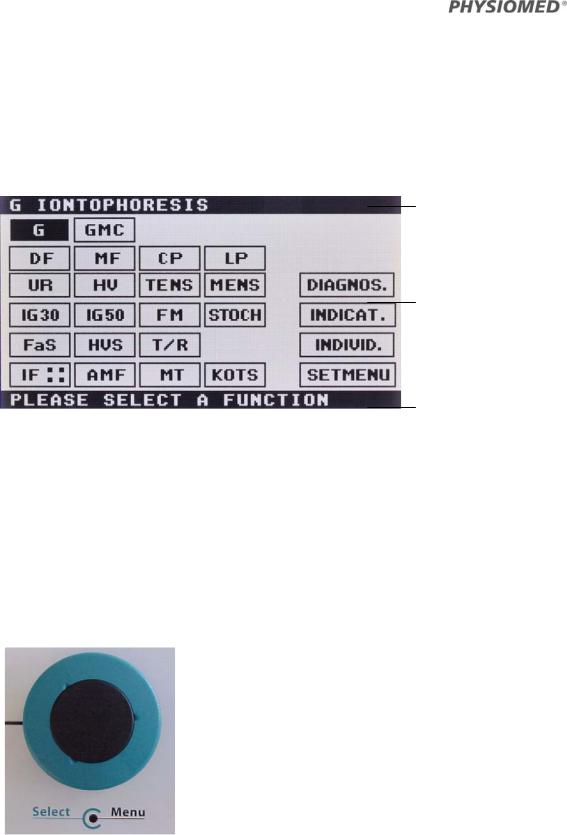
2.2Overview of Parameters
2.2.1 Start Menu (1st level)
upper status bar<2>
current modes with low frequencies (direct access)
current modes with medium frequencies
(direct access)
diagnostics menu
indications menu (therapy suggestions)
individual programs (freely configurable)
lower status bar<4> |
setup menu |
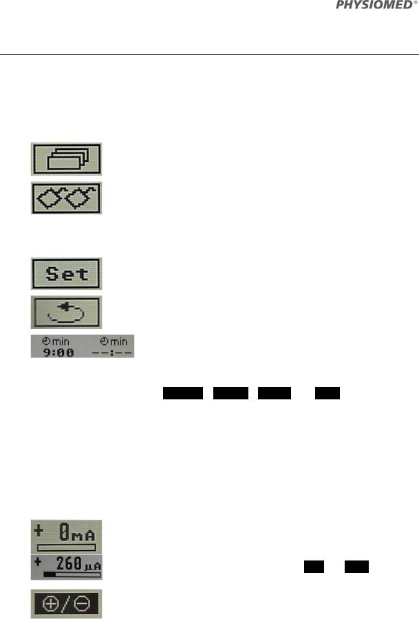
2.2.2Example Menu (2nd level) Current mode FaS
current mode |
parameter |
therapy timers (circuits I + II) |
|
|
|
|
|
|
circuit I
constant voltage operation
parameters circuit I
back to previous menu
individual programs |
setup menu |
electrodes display |
(memory menu) |
(plate electrodes/ |
|
|
|
vacuum electrodes) |
selection circuit II
PHYSIOMED-Expert |
9 |
Controls and Indicators
2.3Operation
Selecting a function (e.g. the current mode  ) from the start menu (level 1) will lead you to level 2 of the menu. Here you can set the desired parameters for the selected current mode.
The following functions are available on level 2:
Memory menu; individual programs (single treatments or current modes) can be memorised.
Display electrodes: Indicates whether the current is released via plate electrodes (this symbol) or via vacuum electrodes. The vacuum electrodes are enabled automatically when switching on the vacuum device. When the vacuum device is switched off, the current is released via plate electrodes (switching is slightly delayed).
Setup menu (settings)
Back to level 1
Therapy timer with selected therapy time; the therapy current will be reduced to 0 and an acoustic signal will be issued every 10 seconds after the countdown. There is one timer for each circuit.
The parameters of the menus DIAGNOS. , INDICAT. , INDIVID. and SETUP will be discussed later.
2.3.1 Parameters for Circuit I
The following paragraph will give you an overview of the meaning of the symbols in the menus for the individual current modes in circuit I.
In General
The symbols below apply for all current modes with low frequencies:
Intensity display circuit I (mA), to be set with
intensity control I <6>. The sign (plus/minus) signifies the polarity of the red plug of circuit I.
Current is measured in μA for current modes GMC and MENS (1,000 μA = 1.000 mA).
Exchange of polarity of the two electrodes;
the sign (plus/minus) of the intensity display will be changed respectively.
10 |
PHYSIOMED-Expert |
Controls and Indicators
Current Modes G, GMC
Switching from galvanic current to medium-frequency interrupted direct current. The current setting is displayed in the upper status bar.
Toggling intensity ranges (0 – 3.5 mA or 0 – 25 mA). The current setting is displayed in the upper status bar (only for  ).
).
Note The maximum intensity of current mode GMC is so small that it is hardly perceptible. Its energy is not sufficient to light Patient current indicator <10> and Output indicator <11>. The displays remain dark therefore.
Current Modes DF, MF, CP, LP
Switching in a galvanic basis (5%).
The current setting is displayed in the upper status bar.
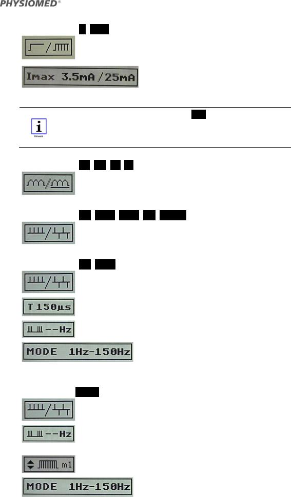
Current Modes UR, IG 30, IG 50, FM, STOCH
Switching from monophase to biphase pulse emission. The current setting is displayed in the upper status bar.
Current Modes HV, TENS
Switching from monophase to biphase pulse emission. The current setting is displayed in the upper status bar.
Pulse time (possible values: 40 μs – 400 μs)
Burst frequency
(possible values: OFF; 1 – 10 Hz, pulse ratios 1:1, 2:1, 1:2)
Frequency bands (70 – 150 Hz or 1 – 150 Hz) or fixed frequency (1 – 200 Hz).
The currently active frequency is displayed in the upper status bar.
Current Mode MENS
Switching from monophase to biphase pulse emission. The current setting is displayed in the upper status bar.
Burst frequency (possible values: Continuous; frequency band 0
– 15 Hz with pulse ratios 1:1, 1:2, 2:1; or selectable burst frequency 0.1 – 15 Hz with pulse ratios 1:1, 1:2, 2:1)
Burst shape (selectable: m1: rectangular, m2/m3/m4: triangular; m5: exponential)
Frequency bands (50 – 300 Hz, 50 – 200 Hz, 200 – 300 Hz; or fixed frequency 10 Hz; or selectable 50 – 300 Hz).
PHYSIOMED-Expert |
11 |
Controls and Indicators
The currently selected frequency is displayed in the upper status bar.
Note The maximum intensity of current mode MENS is so small that it is hardly perceptible. Its energy is not sufficient to light Patient current indicator <10> and Output indicator <11>. The displays remain dark therefore.
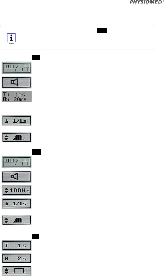
Current Mode FaS
Switching from monophase to biphase pulse emission. The current setting is displayed in the upper status bar.
Acoustic signal, makes every current pulse audible
Ti: Pulse time, possible values: 0,1 – 10 ms
Ri: Release time , possible values: 10 – 250 ms
Pulse shape (triangle, rectangle)
Basic settings: T = 1ms, R = 20 ms, triangular pulse
Relation contraction (Tension, 1 s) / pause (Release, 1 s), possible values T = 1 – 60 s, R= 1 – 60;
manual release key (only if R > 1s)
Ramp (4 settings m1 to m4) with different rise times. The current setting is displayed in the upper status bar.
Current Mode HVS
Switching from monophase to biphase pulses. The current setting is displayed in the upper status bar.
Acoustic signal, makes every current pulse audible.
Frequency (possible values: 2 – 200 Hz)
Relation contraction (Tension, 1 s) / pause (Release, 1 s), possible values T = 1 – 60 s, R= 1 – 60;
manual release key (only if R > 1s)
Ramp (4 settings m1 to m4) with different rise times. The current setting is displayed in the upper status bar.
Current Mode T/R
Pulse time (possible values: 1s – 0.1 ms)
Release time (possible values: 7 s to 1 ms; manual release key)
Pulse shapes (square-wave pulse r1, trapezoidal pulses t1 – t3, triangular pulses d1 – d3, exponential pulse e1). The current setting is displayed in the upper status bar.
12 |
PHYSIOMED-Expert |
Controls and Indicators
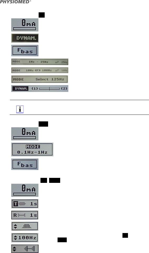
Current Mode IF::
Intensity display circuit I / II (mA), to be set with intensity control I <6> and intensity control II <8>.
Vector function (dynamic function) ON/OFF
Basic frequency (range: 2.0 to 9.5 kHz)
Frequency bands: 4 fixed,
one free programmable,
fixed frequency (Select 1 – 250 Hz)
Interference vector display
Note The current mode IF requires both circuit I and II simultaneously. You cannot select any additional therapy for circuit II.
Current Mode AMF
Intensity display for circuit I, (mA), to be set with intensity control I <6>
5 pre-set frequency bands,
fixed frequency ( SELECT 0 – 250 Hz)
Basic frequency (possible values: 2.0 – 9.5 kHz)
Current Modes MT, KOTS
Intensity display circuit I, to be set with intensity control I <6>
Tension time (possible values: 1 to 60 s in steps of 1s; manual release key (only if R > 1s)
Release time (possible values: 1 to 60 s) in steps of 1s
Ramp (4 settings m1 to m4) with different rise times. The current setting is displayed in the upper status bar.
Modulation frequency (selectable: 0 – 125 Hz for MT, 0 – 95 Hz for KOTS)
Pulse shape (sine, triangle, rectangle)
PHYSIOMED-Expert |
13 |
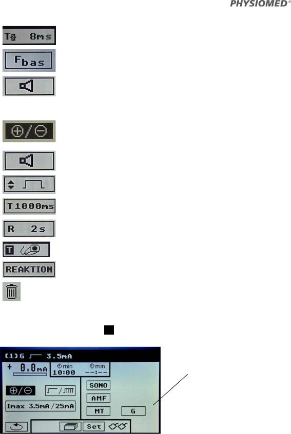
Controls and Indicators
Pulse length T
(possible values: 2 ms, 4 ms, 6 ms, 8 ms, 10 ms, auto)
Basic frequency (possible values: 2.0 – 9.5 kHz)
Acoustic signal, makes every current pulse audible
2.3.2 Parameters for i/t-diagnostics
Exchange of polarity of the two electrodes;
the sign (plus/minus) of the intensity display will be changed respectively.
Acoustic signal, makes every current pulse audible
Pulse forms:
Select between rectangular pulse r1 and triangular pulse d1
Pulse time:
Selecting the pulse time (steps from 1000 ms – 0,1 ms)
Pause time:
Selecting the time between the pulses (steps from 2-5 s)
Trigger pulses with manual release key
Confirm muscular reaction
Delete stored values
2.3.3 Dual channel operation
For all current modes except IF:: you can select additional current modes (dual channel operation) in circuit II .
All current modes can be applied in both circuits
2.3.3.1 For all current modes except IF, GMC and MENS
The current mode set in circuit I can also be selected with the same parameters in circuit II. AMF and MT can always be selected.
14 |
PHYSIOMED-Expert |
Controls and Indicators
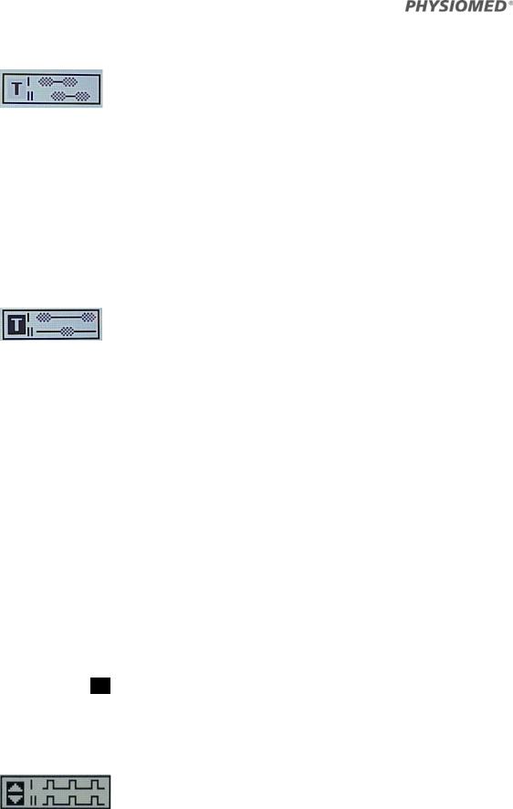
2.3.3.2 For the current modes FaS and HVS
The current mode set in circuit I can also be selected in circuit II, whereby individual parameters can be set independently for both circuits. With circuits I and II, stimulation can be either simultaneous or alternating. Carry out the following operational steps:
(1)Select the desired current mode in both circuits.
(2)With the data selector <5>, first click on the  selection field in circuit II. A further window will open.
(3)In the new window, click on the  selection field, turn the selector at least one step to the right and confirm this.
(4)In the same window, click on the  selection field and turn the selector to the left until the desired icon appears (e.g. for simultaneous stimulation).
(5)Leave the window via the  button.
Simultaneous stimulation
Circuits I and II stimulate simultaneously with the same parameters. The polarity and ramp of the surge current can be freely selected in each circuit.
To adjust the threshold time and threshold interval, carry out the operational steps 1-5 described above, and then proceed as follows:
(6)With the data selector <5>, first click on the  selection field in circuit I.
(7)In the new window, click on the  selection field, turn the selector to the right and select the duration of the surge interval.
(8)In the same window, click on the  selection field, turn the selector to the right and select the duration of the surge time.
(9)Leave the window via the  button.
Simultaneous stimulation can also be initiated with the manual release key. Carry out the above-described operational steps 1-5, and then proceed as follows:
(6a) With the data selector <5>, first click on the  selection field in circuit I.
(7a) In the new window, click on the  selection field, turn the selector at least one step to the right and confirm this.
(8a) In the same window, click on the  selection field and turn the selector to the left until the manual release key icon
  appears.
(9a) Leave the window via the  button.
(10a) Insert the manual release key into the manual release key socket <13> at the rear of the equipment.
The length of the surge currents in circuits I and II is determined by the pressure on the manual release key.
If you have set up the manual release key in both circuits, then simultaneous stimulation will also follow.
PHYSIOMED-Expert |
15 |
Controls and Indicators
Alternating stimulation (continuous transition between circuits I and II)
Circuits I and II provide alternating stimulation, one directly after the other.
A surge cycle follows, consisting of:
(1)Surge current in circuit I in the selected length
(2)No pause
(3)Surge current in circuit II in the selected length
(4)Pause for the selected length
To set the surge time and surge pause, carry out steps 1-9, described above.
Alternating stimulation can also be controlled with the manual release key. To do this, carry out steps 1-5 and 6a-10, described above.
Alternating stimulation (defined pauses between circuits I and II)
Circuits I and II provide alternating stimulation, with defined pauses between the surges in circuits I and II.
The surge times and surge pauses are adjusted in circuit I. To do this, carry out steps 1-9, described above.
Alternating stimulation can also be controlled with the manual release key. To do this, carry out steps 1-5 and 6a-10, described above.
2.3.3.3 For the MT and KOTS current modes
The current form set in circuit I can also be selected in circuit II, whereby individual parameters can be set independently for both circuits. With circuits I and II, stimulation can be either simultaneous or alternating, or controlled with the manual release key.
The settings are made as described on page 14, whereby  and
and  are not set via a separate window.
2.3.3.4 For the T/R current mode
The current mode set in circuit I can also be selected in circuit II, whereby all parameters can be set independently for both circuits. With circuits I and II, stimulation can be either simultaneous or alternating, or controlled with the manual release key.
To make adjustments, carry out the following operational steps:
(1)Select the T/R current mode in both circuits.
A selection field appears in circuit II with which you can adjust the type of stimulation (simultaneous or alternating)
Simultaneous stimulation
Circuits I and II stimulate simultaneously with the same parameters. The setting is made via the selection fields  : Pulse time,
  : pause duration and via the pulse form. Polarity can be freely selected in each circuit.
Simultaneous stimulation can also be initiated with the manual release key. To do this, carry out the following operational steps:
16 |
PHYSIOMED-Expert |
Controls and Indicators
(2)With the data selector <5>, click on the  selection field and turn fully to the right until the manual release key icon appears.
(3)Click on the  selection field and choose the desired pulse duration for circuits I and II.
(4)Insert the manual release key into the manual release key socket <14> at the rear of the equipment.
Alternating stimulation (continuous transition between circuits I and II)
Circuits I and II provide alternating stimulation, one directly after the other (delay time: 50 ms).
A surge pulse cycle follows, consisting of:
(1)Pulse in circuit I in the selected length and form
(2)Delay 50 ms
(3)Pulse in circuit II in the selected length and form
(4)Pause for the selected length
Pulse time  , pause time
  , pulse form and polarity can be freely selected in each circuit.
First, carry out operational step 1, as described above.
(3)Click on the  selection field, turn the data selector <5> one step to the right and confirm this.
Additional selection fields for circuit II will appear.
(4)Click on the  selection field in circuit I and choose the desired pulse duration for circuit I.
(5)Click on the  selection field in circuit II and choose the desired pulse duration for circuit II.
(6)Click on the  selection field and choose the desired pause duration.
(7)To set the pulse forms and polarity in both circuits, click on the  and
and
 selection fields.
Alternating stimulation can also be initiated with the manual release key.
First, carry out operational steps 1 and 2, as described above.
(3a) With the data selector <5>, click on the  selection field and turn fully to the right until the manual release key icon appears.
(4a) Click on the  selection field in circuit I and choose the desired pulse duration for circuit I.
(5a) Click on the  selection field in circuit II and choose the desired pulse duration for circuit II.
(6a) To set the pulse forms and polarity in both circuits, click on the  and
and  selection fields for each circuit.
(7a) Insert the manual release key into the manual release key socket <13> at the rear of the equipment.
PHYSIOMED-Expert |
17 |

Controls and Indicators
Alternating stimulation (defined pauses between circuits I and II)
Circuits I and II provide alternating stimulation, with defined pauses between the surge currents in circuits I and II.
Pulse time  , pause time
  , pulse form and polarity can be freely selected in each circuit.
First, carry out operational steps 1 and 2, as described above.
(3)Click on the  selection field in circuit I and choose the desired pulse duration for circuit I.
(4)Click on the  selection field in circuit II and choose the desired pulse duration for circuit II.
(5)Click on the  selection field and choose the desired pause duration.
(6)To set the pulse forms and polarity in both circuits, click on the  and
and
 selection fields for each circuit.
Alternating stimulation can also be initiated with the manual release key.
First, carry out operational steps 1 and 2, as described above.
(3a) With the data selector <5>, click on the  selection field and turn fully to the right until the manual release key icon appears.
(4a) Click on the  selection field in circuit I and choose the desired pulse duration for circuit I.
(5a) Click on the  selection field in circuit II and choose the desired pulse duration for circuit II.
(6a) To set the pulse forms and polarity in both circuits, click on the  and
and  selection fields for each circuit.
(7a) Insert the manual release key into the manual release key socket <13> at the rear of the equipment.
18 |
PHYSIOMED-Expert |
Loading...