Physiomed Expert 2, IF–Expert 2 User manual

S E R V I C E M A N U A L
PHYSIOMED-Expert 2
PHYSIOMED–IF–Expert 2
Revision: 09 / 2008
Valid from Instrument No.: PME 2 - 0300211
And PIE 2 - xx001xx 17900
Table of Contents
1 |
TECHNICAL DATA................................................................................................. |
3 |
||
2 |
HOUSING CONSTRUCTION................................................................................... |
4 |
||
3 |
GENERAL NOTES .................................................................................................. |
4 |
||
4 |
NOTE |
..................................................................................................................... |
4 |
|
5 |
ADDITIONAL EQUIPMENT REQUIRED.................................................................. |
4 |
||
6 |
TEST MENU ........................................................................................................... |
5 |
||
|
6.1 |
Test Menu Stimulation Current ................................................................................................ |
5 |
|
7 |
BALANCING .....................................................................................PROCEDURE |
6 |
||
|
7.1 |
Setting ...................................................................................................................................up |
6 |
|
|
7.2 |
Checking ..................................................................the Power Supply; PC Board No. 9902-2 |
7 |
|
|
7.2.1 ....................................................................................................................... |
Not Stabilized |
7 |
|
|
7.2.2 ............................................................................................................................. |
Stabilized |
7 |
|
|
7.3 |
Balancing ...........................................................PC-Board No.: 9902-2 (Stimulation Current) |
7 |
|
|
7.3.1 .................................................................Balancing I: Offset Set Up of Output Transformer |
7 |
||
|
7.3.2 ....................................................................Balancing II: Offset Set Up of Pulse Generation |
7 |
||
|
7.3.3 .............................................................................................Adjustment of Output Current |
8 |
||
8 |
CHECKING ..............................................................................THE INSTRUMENT |
9 |
||
|
8.1 |
Checking .................................................................................................................Connection |
9 |
|
|
8.2 |
Checking ..................................................................................Display and Display Elements |
9 |
|
|
8.3 |
Checking ...................................................................................................the Therapy Timer |
10 |
|
|
8.4 |
Checking ....................................................................................................the Current Types |
10 |
|
|
8.5 |
Checking .............................................................................Function of the Selection Fields |
10 |
|
|
8.6 |
Display .....................................................................Wire of Air Gap and Leakage Distance |
10 |
|
9 |
ERROR .....................................................................................................CODES |
11 |
||
|
9.1 |
Important ...........................................................................................................Service Note |
12 |
|

|
|
Technical Data |
|
|
|
1 Technical Data |
|
|
Protection class |
I acc. To VDE 0750 / IEC 601 |
|
|
Typ: BF |
|
CE characterization |
acc. to Council Directive concerning medical devices |
|
|
(93/42 EEC) |
|
Class acc. EEC 93/42 |
IIa |
|
Power supply |
230 VAC ± 10% or 115 VAC ± 10% |
|
|
Note Settings indicated at the mains module! |
|
Power line frequency |
50 … 60 Hz |
|
Current consumption |
0.3 A (at 230 V) or 0.6 A (at 115 V) |
|
Power consumption |
68 VA |
|
Line fuses |
at 230 V: |
T 1 A |
|
at 115 V: |
T 2 A |
Output data |
75 mAs (maximum) at 500 Ohm |
|
STIMULATION |
|
|
Ambient temperature |
+ 10°C ... + 40°C |
|
Dimensions |
34.5 x 13.3 x 34.8 cm |
|
(W x H x D) |
|
|
Weight |
5.1 kg |
|
PHYSIOMED-Expert 2 - Service Manual |
3 |

Housing Construction
2 Housing Construction
PHYSIOMED-Expert 2 / PHYSIOMED-IF-Expert 2 housing.
Always disconnect the power lead before opening the instrument.
3 General Notes
PHYSIOMED-Expert 2 / PHYSIOMED-IF-Expert 2 is a two-channel stimulation current therapy unit. You can apply the whole range of current modes from lowto medium-frequency including the classic interferential current. The instrument also offers you programs for diagnosis by stimulation current. The unit can also be used for simultaneous therapy (stimulation current and ultrasound in ONE treatment if you combine it with a suitable ultrasound therapy unit (e.g. PHYSIOSON-Expert).
4 Note
The structure of the following service instructions allows you to do a basic balancing.
As a rule, for later balancing (e.g. repair), only parts of the balancing procedure are necessary, which can all be adjusted by the trimming potentiometer (provided that grave errors concerning the balancing procedure are not apparent or have been cleared).
5 Additional Equipment Required
|
State of calibration * |
Oscilloscope (with probe) |
B |
Digital multimeter AC and DC |
B |
Frequency meter |
B |
* State of calibration B = precision 5%
The following documents provide information necessary for the balancing procedure, such as positions of the trimmers or test points:
•Wiring Scheme
•Parts List
•Operating Instructions
4 |
PHYSIOMED-Expert 2 - Service Manual |

Test Menu
6 Test Menu
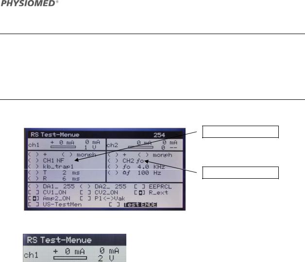
The test menu is used to select and display service relevant parameters of the instrument. In order to get into the test menu you have to set short-circuit plug JP2 at Pc board 9902-2 on position 1+2 and then turn on the instrument.
6.1 Test Menu Stimulation Current
Selection Channel 1
Selection Channel 2
Display Circuit: Set Value I
Value measured output I
Value measured output U
PHYSIOMED-Expert 2 - Service Manual |
5 |

Balancing Procedure
You will find a similar layout of the display for circuit II (ch2). By using the following overview table you can get information for possible adjustable parameters and displays:
|
|
Selection Field Circuit I |
Available Options |
|
( |
) |
+ |
|
Positive signal / Negative signal |
( |
) |
CH1 NF |
NF/ MF / MC basic signals |
|
( |
) monph |
Monophasic signal / Biphasic signal |
||
( |
) |
kb_trap1 |
Signal waveform |
|
( |
) |
T |
|
Impulse duration of the signal |
( |
) |
R |
|
Pause duration of the signal |
|
|
Selection Field Circuit II |
Available Options |
|
( |
) |
+ |
|
Positive signal / Negative signal |
( |
) monph |
(unused; CH1 also switches CH2) |
||
( |
) CH2 |
f0 |
f0 / AMF / NF / NF_HV / NF_2 basic signals |
|
( |
) |
f0 4 KHz |
Adjusting of basic frequency |
|
( |
) |
f |
100Hz |
Adjusting of modulation frequency |
|
|
Lower Selection Field |
Available Options |
|
( |
) DA1_255 |
Adjust circuit I by means of the DA converter |
||
( |
) DA2_255 |
Adjust circuit II by means of the DA converter |
||
[ |
] |
EEPRCL |
EPROM clear (e.g. clearing all individual programs) |
|
[ |
] CV1_ON |
Activate constant voltage |
||
[ |
] CV2_ON |
Activate constant voltage |
||
[ |
] |
R_ext |
Switch signal to external lead resistor |
|
[ |
] Amp2_ON |
Activate output transistor in circuit 2 |
||
[ |
] |
Pl Ù Vak |
Switching between plate electrodes – vacuum |
|
|
|
|
|
electrodes |
[ |
] US-TestMen |
Selection of the ultrasound test menu (unused) |
||
[ |
] Test END |
Exit test menu |
||
7 Balancing Procedure
7.1Setting up
•Check line fuses; refer to technical data and reference labels.
•Check fuses F1-F4 of secondary circuit; refer to parts list of power supply and to reference labels.
•Connect power cord
6 |
PHYSIOMED-Expert 2 - Service Manual |
 Loading...