

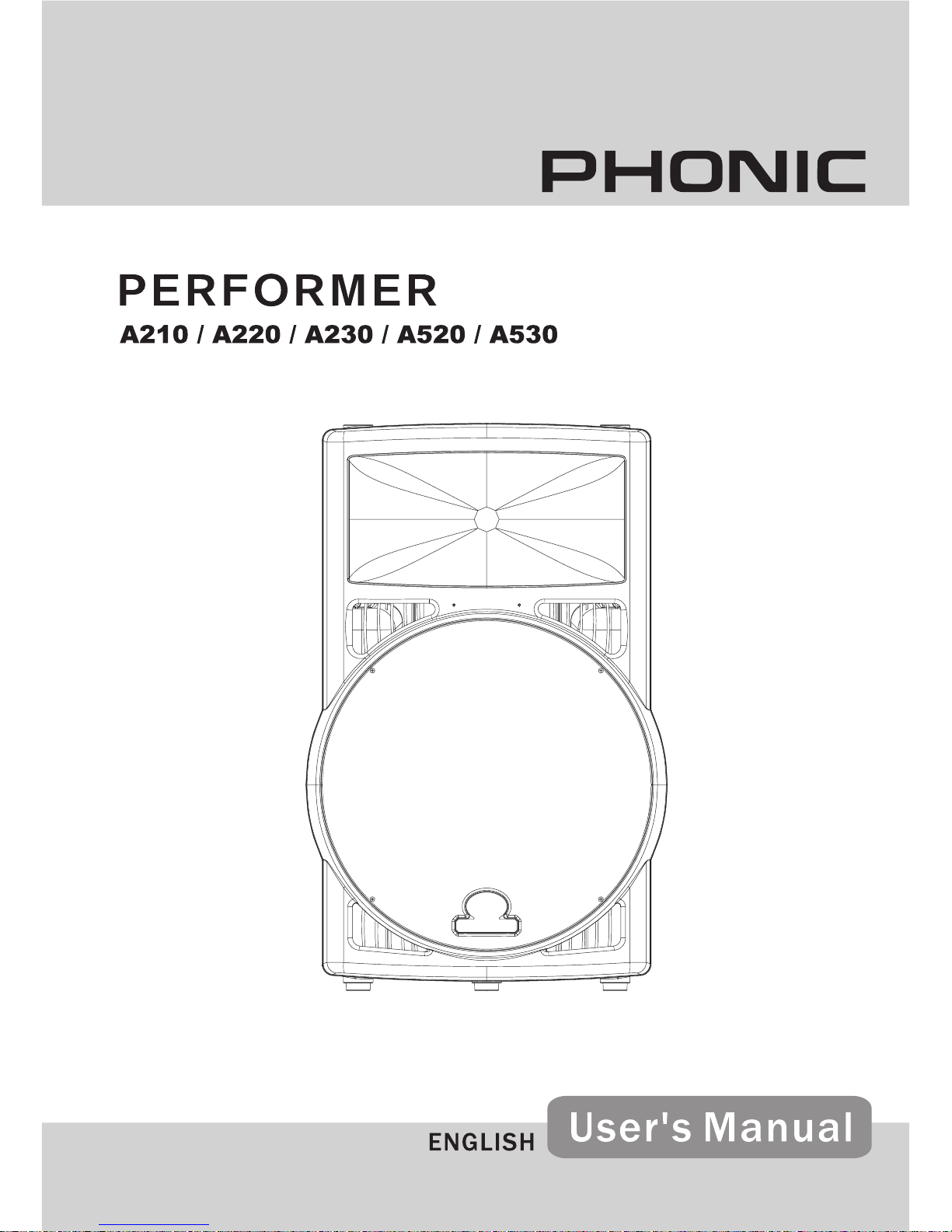
Phonic performer A220, performer A210, performer A530, performer A520, performer A230 User Manual
Page 1
Page 2

Page 3

TAB LE OF CONTENT S
page
PHONIC PERFORMER ACTIVE SPEAKER SERIES
PERFORMER A210 / A220 / A230 / A520 / A530
Phonic reserves the right to improve or alter any information suppied within this document without prior notice.
V1.0 JAN 14, 2005
SAFETY INSTRUCTIONS..........................................................................4
INTRODUCTION ........................................................................................5
PERFORMER ACTIVE SPEAKER FEATURES ........................................6
QUICK START ............................................................................................7
REAR PANEL DESCRIPTION ...................................................................8
HOOKUP DIAGRAMS ..............................................................................10
Wired Setup ........................................................................................10
Wireless Setup ................................................................................... 11
INSTALLING WIRELESS MODULES ......................................................15
OPTIONAL ACCESSORIES ....................................................................16
PURCHASING OPTIONAL ACCESSORIES ...........................................17
SERVICE AND REPAIR ...........................................................................17
CUSTOMER SERVICE AND TECHNICAL SUPPORT ...........................17
SPECIFICATIONS ....................................................................................18
DIMENSIONS ...........................................................................................19
Page 4

Performer User's Manual PHONIC CORPORATION
page 4
PHONIC CORPORATION Performer User's Manual
page 5
SAFETY INSTRUCTIONS
1. Read all instructions carefully before using your Performer Active Speakers.
2. Keep this user's manual for future reference.
3. Please carefully follow all instructions.
4. Do not use these speakers with ampliers or the powered output of a powered mixer. They should only
be used with a mic- or line-level input. An amplier generates a much higher current level which will
damage Performer active speakers.
5. Warning - Performer active speakers generate extremely high sound pressure levels. Take care in the
placement and operation of speakers to avoid prolonged exposure to extremely high sound levels. Long
exposure to high sound pressure levels may cause permanent hearing loss.
6. Cables - You should use properly functioning cables with XLR-type and 1/4" phone connectors to
connect microphones or mixers to the Performer active speakers.
7. Mounting - The suspending, rigging and mounting of Performer active speakers can cause members
of the public to be exposed to serious risk or even death in the event that a poorly installed speaker
should come loose and fall. If you are NOT fully qualied and certied by relevant local, state or national
authorities to mount these speakers, call a qualied technician to install them and do not install them
yourself. All relevant safety regulations must be followed. If you are not completely qualied, or there
are no regulations in your area governing said installation, please consult qualied personnel for
assistance.
8. Servicing - Do not under any circumstances try to service this product yourself. If servicing is required,
contact your local service center.
Page 5

PHONIC CORPORATION Performer User's Manual
page 5
INTRODUCTION
Congratulations on your purchase of the world's rst wireless professional audio speaker. Performer
active speakers utilize the ultra-fast 2.4 GHz bandwidth to communicate with your mixer and other
Performer speakers. They can also receive and broadcast wireless microphone signals without any
cabling. Performer Series speakers have an attractive yet impact-resistant design. The angled molded
enclosure is made of highly durable polypropylene and is designed for use as a stage monitor, standmounted speaker or for permanent installation.
Active Speaker Technology
Active speaker technology means that Performer speakers have more power and better quality sound. In
conventional powered speakers, the power amplier’s output is sent to a passive crossover in the speaker,
where it is separated into high and low frequencies and sent to the transducers. The simple construction
of passive crossovers means they tend to do an especially poor job sending the high frequencies to the
driver. They also lose a lot of power in the process - up to 30%.
The active speaker difference starts with the crossover. Our Performer active speakers use an electronic
Linkwitz-Riley 24 dB crossover. An electronic crossover is much more complex than a passive crossover.
The electronic crossover intelligently divides the frequencies and sends them to the built-in high- and lowfrequency transducers. Since the electronic crossover processes a line-level signal, much less power is
lost before the signal is sent to the ampliers. And since each Performer active speaker has two built-in
ampliers, we are able to custom tailor their output for each speaker. In this way there is virtually no power
lost by the crossover, or by the ampliers being forced to drive high and low transducers at the same
time. You will be surprised at the power your Performer active speakers deliver and how well they perform
through all the frequencies.
Wireless Capability
Performer active speakers are wireless-enabled. They can be congured to work wirelessly with a wireless
microphone, to receive wireless transmission from a mixer, or both. Performer active speakers even have
the capability to communicate wirelessly with other Performer active speakers. Wireless modules (not
included) are easy to install and take your Performer active speaker to the next level.
One of the great things about wireless capability is that you don't have to worry about matching load
impedances and excessive loading on the source. For instance, with most active speakers, if you are
using a wired microphone you can only daisy chain a maximum of two speakers together before excessive
loading of the source occurs. However, with Performer active speakers tted with wireless modules, this is
not a problem. You can use the wireless modules to "virtually" daisy chain as many speakers as you want
- even if you are using a wired microphone.
Our engineers designed Performer active speakers to incorporate the latest technology in a quality
speaker that can be used in almost any application. Whether you use the Performer for live sound,
in a studio, for boardroom meetings or install it in a house of worship, it will provide you with listening
enjoyment for years to come.
Page 6
Performer User's Manual PHONIC CORPORATION
page 6
PHONIC CORPORATION Performer User's Manual
page 7
PERFORMER ACTIVE SPEAKER FEATURES
Common Features
Mic / Line Balanced Preamp
75 Hz Low Cut Filter (18 dB/oct.)
Contour Switch with 5 dB boost @ 80 Hz
(1/3oct.) and 5 dB boost @ 10.5 KHz (1/3oct.)
Switching Power Supply (115-230V, 50-60 Hz)
Built-in limiter protects against overload
Optional wireless modules for transmitting and
receiving
Optional wireless microphone system
Durable, lightweight speaker cabinet with
dynamic sound
1" tweeter with 90° x 60° sound dispersion
Balanced XLR-type and 1/4" phone jack inputs
with switched Mic/Line sensitivity plus an XLRtype LINK OUT
35mm socket on bottom for pole / stand
mounting
Model Features
Performer A210
Wireless 12" 90W Active Speaker
- 90 Watts RMS
- 12” Woofer
Performer A220
Wireless 12" 160W Active Speaker
- 160 Watts RMS
- 12” Woofer
Performer A230
Wireless 12" 275W Active Speaker
- 275 Watts RMS
- 12” Woofer
Performer A520
Wireless 15" 160W Active Speaker
- 160 Watts RMS
- 15” Woofer
Performer A530
Wireless 15" 275W Active Speaker
- 275 Watts RMS
- 15” Woofer
Page 7

PHONIC CORPORATION Performer User's Manual
page 7
QUICK START
1. Ensure that the POWER switch is off (down) and set the LOW CUT and CONTOUR switches out. Turn
the two volume controls all the way down (counterclockwise).
2. If you plan to use the wireless functions of the Performer, make sure that the proper wireless module(s)
is correctly installed. If you are using the wired conguration, then connect the output from the signal
source (mic- or line-level source) to the matching input on the Performer (mic-level input into the XLRtype female input jack, and line-level input into the 1/4" phone jack). The Performer accepts balanced or
unbalanced mic- or line-level signals from dynamic microphones, mixers, preampliers, CD players, tape
decks, etc. via XLR-type or TRS 1/4" phone connectors.
Note: The Performer will only accept input from condenser microphones that have their own power supply.
3. Set the VOLTAGE SELECTOR switch to the correct voltage setting for your region (100-120 VAC 60 Hz
or 220-240 VAC 50 Hz). Plug the AC power cord into the IEC socket on the back of the Performer active
speaker. Plug the other end of the power cord into an AC outlet.
4. Set the input selector switch to the appropriate input level. Select MIC (up) for mic-level input; select
LINE (down) for line-level input.
5. Turn on the signal source (i.e. mixer, etc.). Ensure that its Master Volume control is turned all the way
down.
6. Switch on the Performer power switch (down).
7. Start the signal source (i.e. speak into the microphone) and adjust the signal source level settings.
8. Slowly turn up the level control on the Performer until you achieve the desired volume. Make sure that
the PEAK light does not come on.
9. If there is no sound, rst turn the Performer level control all the way down before investigating. When you
think you have solved the problem, then repeat step 8 again. Follow Step 9 every time you troubleshoot
until you solve the problem.
Page 8
Performer User's Manual PHONIC CORPORATION
page 8
PHONIC CORPORATION Performer User's Manual
page 9
REAR PANEL DESCRIPTION
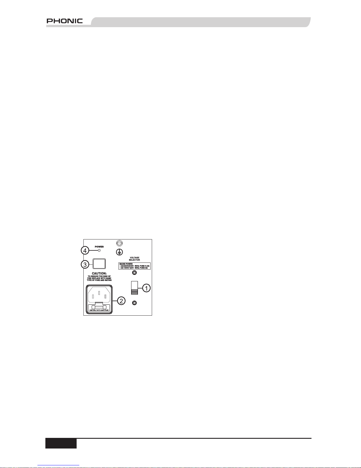
1. VOLTAGE SELECTOR
This switch allows you to select the AC electric
current in use in your region. It is very important
that you select the correct MAINS POWER voltage
before plugging in the power cord. For 220-240
volts 50 Hz, push the switch up. For 110-120 volts
60 Hz, push the switch down. Voltage levels vary
from country to country, (even from city to city in
certain countries). For example, North America
uses a 110-120 volt, 60-cycle (Hz) system, while
the European standard is 220-240 volt, 50-cycle
(Hz).
Note: The U.S. Department of Commerce's International
Trade Administration produces a very useful publication
called "Electric Current Abroad." It is an exhaustive list of
the electric current characteristics of every country (and its
cities, if there is variance) and the type of AC plugs in use
in those countries.
2. IEC Socket
Connect the supplied AC power cord here. Since
Performer active speakers have built-in power
ampliers, you must connect them to an AC power
supply or you won't get any sound.
Note: If you happen to leave the power cord behind at a
gig, don't worry. The 3-pin plug with ground pin is readily
available at most ofce and computer supply stores.
3. POWER Switch
To turn on the Performer active speaker set the
POWER switch in (down). To turn off the Performer
set the switch out (up). Make sure the volume
control is all the way down before you turn the
power on or off.
4. POWER On Indicator
This LED indicator is located just above the
POWER switch. When the POWER is on and
the Performer is connected to an active AC Mains
supply, this indicator glows.
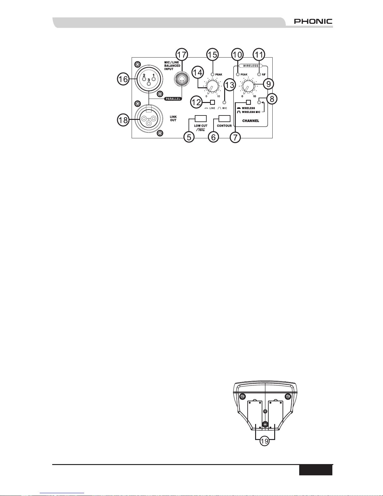
5. LOW CUT
This switch engages or disengages the low cut
lter. Turn on the low cut lter by setting the switch
in (down). To turn it off set the switch out (up).
The low cut lter cuts out frequencies below the
75 Hz range. It is especially useful for eliminating
unwanted noise like stage rumble, P-pops and
wind noise. It's also a good idea to use the low
cut lter when using the Performer as a stage
monitor.
6. CONTOUR
Use this feature when working in live sound
applications. Pushing in the switch gives a 5 dB
boost to frequencies below 80 Hz and above 10.5
KHz, making your highs clearer and giving your
bass more kick. Try out the sound with the contour
switch in and out to see which sounds best for your
application.
7. WIRELESS/WIRELESS MIC Switch
This switch allows you to select between
the different types of wireless signals being
transmitted to the Performer active speaker. To
select the wireless microphone, rst ensure that
the correct wireless module is installed, and then
set the switch out (up). To select a wireless signal
coming from another wireless source, such as
a wireless mixer transmission module or from
another Performer active speaker, ensure that the
correct wireless module is installed, and then set
the switch in (down). (For more information about
wireless microphones and modules, please refer
to page 16.)
8. Signal Indicator (Wireless)
After selecting WIRELESS or WIRELESS MIC,
this LED lights up whenever the selected signal
is present.
9. Wireless Volume Control
Use this rotary control to set the volume level
for the wireless input signal. It's a good idea to
rst turn the volume control all the way down
(counterclockwise). Turn on the selected source
signal and then slowly turn up the volume control
until you reach the desired volume level (but not
until the PEAK indicator lights up).
Note: If you are not using the wireless function of this
speaker, it is best to turn the volume all the way down to
avoid picking up any radio frequency interference.
10. PEAK Indicator (Wireless)
This LED illuminates when the signal levels at the
amplier outputs approach clipping. It's OK for the
PEAK indicator to blink infrequently, but if it blinks
Page 9
PHONIC CORPORATION Performer User's Manual
page 9
often or is always lit, then you should turn down
the volume level of either the signal source or the
Performer.
11. RF Indicator (Wireless)
The RF indicator lights up when it detects the
signal from the wireless microphone or other
device.
12. LINE/MIC Switch
This switch allows you to select between the
balanced line input (TRS 1/4") and the balanced
microphone input (XLR female) input. To select
the line input, set the switch in (down). To select
the microphone input, set the switch out (up).
13. Signal Indicator
After selecting LINE or MIC, this LED lights up
whenever the selected signal is present.
14.MIC/LINE Volume Control
Use this rotary control to set the volume level
for MIC/LINE BALANCED INPUT signal(s). It's
a good idea to rst turn the volume control all
the way down (counterclockwise). Turn on the
selected source signal and then slowly turn up
the volume control until you reach the desired
volume level (but not until the PEAK indicator
lights up).
15. PEAK Indicator
This LED illuminates when the signal levels at
the amplier outputs approach clipping. It's OK
for the PEAK indicator to blink infrequently, but if
it blinks often or is always lit, then you should turn
down the volume level of either the signal source
or the Performer.
16. INPUT Connector (Mic)
This is a female XLR-type connector that accepts a
balanced or unbalanced mic-level signal.
17. INPUT Connector (Line)
This is a female TRS 1/4" phone connector that
accepts a balanced or unbalanced line-level
signal.
18. LINK OUT Connector
This is a female XLR-type connector that can
be used to daisy chain multiple Performer active
speakers together. It produces exactly the same
signal that is connected to either of the two input
jacks. However, if the MIC/LINE Volume Control is
turned past two o'clock on the dial, the Performer
active speaker will add +6 dB to the signal. This
helps to strengthen weak input signals and
improve the overall quality of your sound.
19. Wireless UHF, VHF and 2.4 GHz Module
Compartments
The top of the Performer active speaker has two
compartments for installation of wireless modules.
Each compartment can t one module and has a
cover held in place by two screws.
Note: For instructions on how to select the input from the
wireless module(s) please refer to (7) and (9) above. (For
instructions on installing wireless modules, please refer to
page 15.)
Page 10
Performer User's Manual PHONIC CORPORATION
page 10
PHONIC CORPORATION Performer User's Manual
page 11
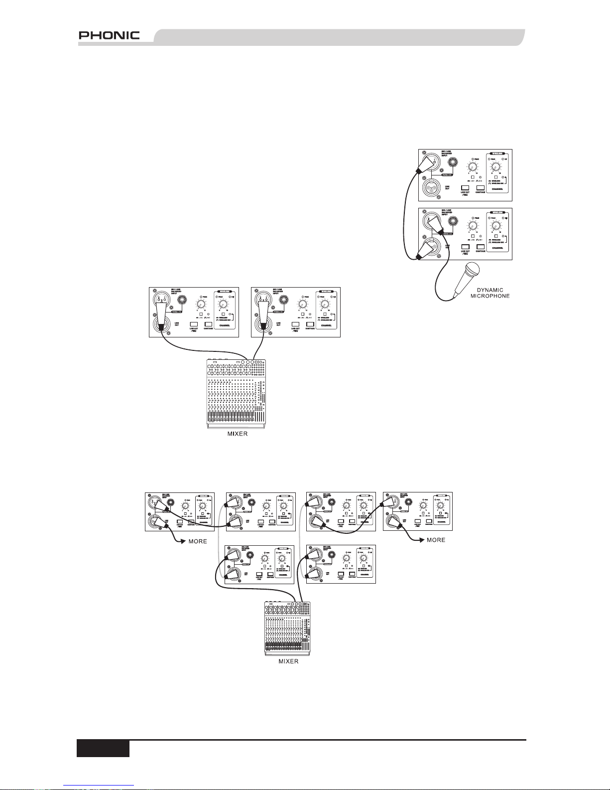
Wired Setup
1) Dynamic microphone with two Performer active speakers daisy
chained together using the LINK OUT.
Note: The Performer active speaker does not have phantom power, so you will
not be able to use it in conjunction with a condenser microphone unless the
microphone has its own power supply.
2) Mixer with stereo left and right mic-level output divided to left- and
right-side speakers.
Note: You must use the 1/4" phone connectors on the Performer active speaker
if you want to use a line-level input.
3) Mixer with stereo left and right mic-level output divided to left- and right-side speakers. The Performer
active speakers are daisy chained together using the LINK OUT.
HOOKUP DIAGRAMS
Due to the ability to use Performer active speakers for wired or wireless applications, there are many possible
congurations. Here we address the most probably applications for your Performer active speaker.
Page 11
PHONIC CORPORATION Performer User's Manual
page 11
Wireless Setup
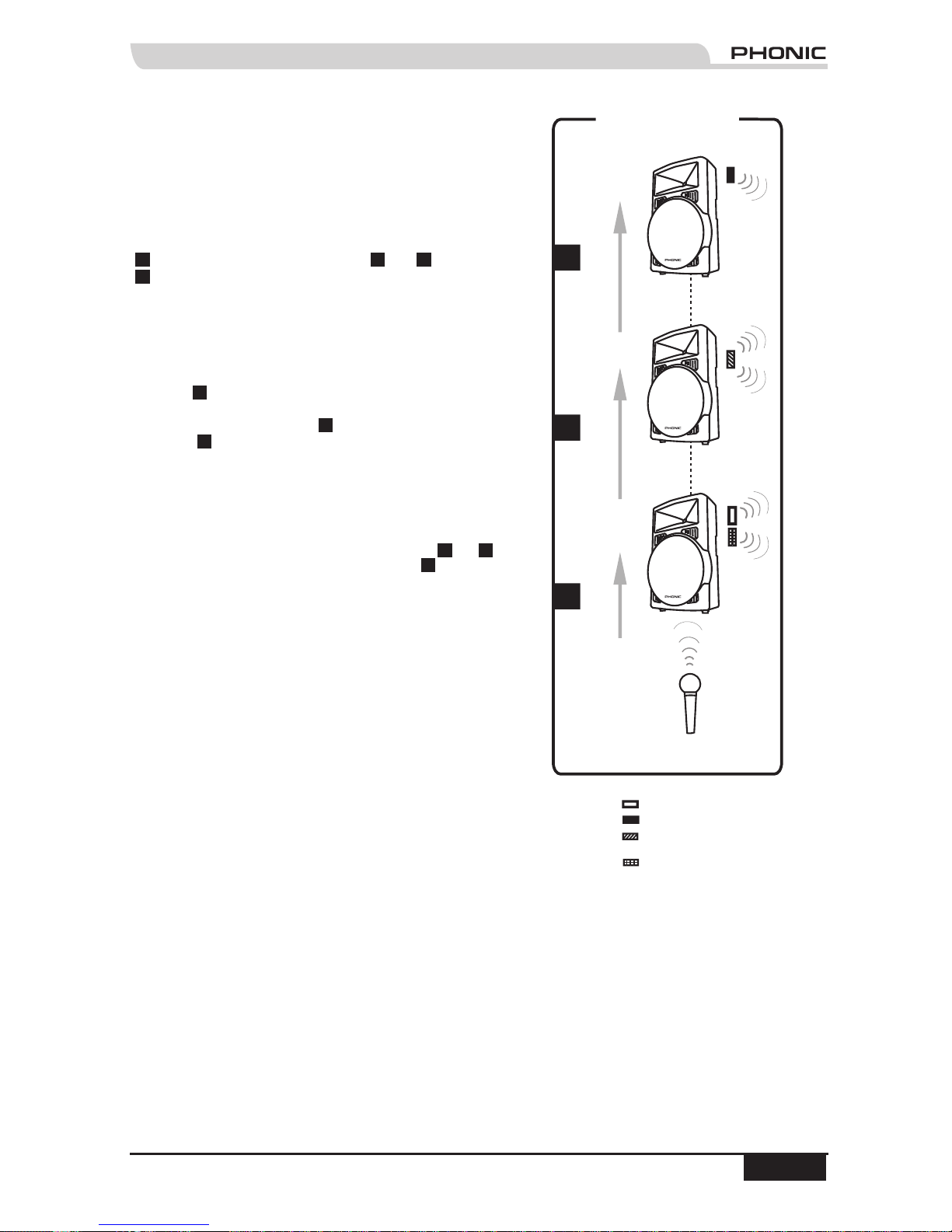
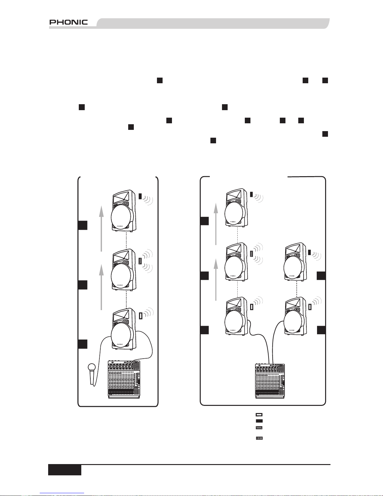
4) System One:
This conguration uses a Phonic wireless microphone
with three Performer active speakers. You can use a
Phonic UHF or VHF wireless microphone with wireless
module to transmit to the speakers. Set the WIRELESS/
WIRELESS MIC Switch out (up) on the back of Speaker
1
, and set it in (down) on Speakers
2
and
3
. Speaker
1
is tted with two wireless modules installed in the
two compartments on the top of the speaker. One
compartment has the matched-frequency wireless
module for the UHF or VHF wireless microphone. The
other compartment is tted with a Wireless Transmitter
Module (WM 30) for re-transmitting the source signal
to other wireless-enabled Performer active speakers.
Speaker
2
is tted with a Wireless Transmitter/Receiver
Module (WM 50) for receiving the source signal
transmission from Speaker
1
and re-transmitting it to
Speaker
3
, which is tted with a Wireless Receiver
Module (WM 40). In this way you have a completely
wireless system with all the speakers receiving the same
signal from the wireless microphone. (To install wireless
modules please refer to the instructions on page 15.)
Note: The Wireless Transmitter modules (WM 30 and WM 50)
have a range of up to 100 feet (30 meters). If Speakers
2
and
3
are both within that range of distance from Speaker
1
, then they
only need to be tted with a Wireless Receiver Module (WM 40).
Related Products: UM 11, UM 22, VM 11, VM 22, WM
30, WM 40, WM 50
VHF / UHF Wireless
Microphone
Performer Speaker
SYSTEM ONE
Performer Speaker
1
3
2
up to 100 feet
(30 meters)
up to 100 feet
(30 meters)
up to 300 feet
(100 meters)
Performer Speaker
2.4 GHz Transmitter (WM30)
2.4 GHz Receiver (WM400)
2.4 GHz Transmitter /
Receiver (WM50)
VHF / UHF Receiver
Page 12
Performer User's Manual PHONIC CORPORATION
page 12
PHONIC CORPORATION Performer User's Manual
page 13
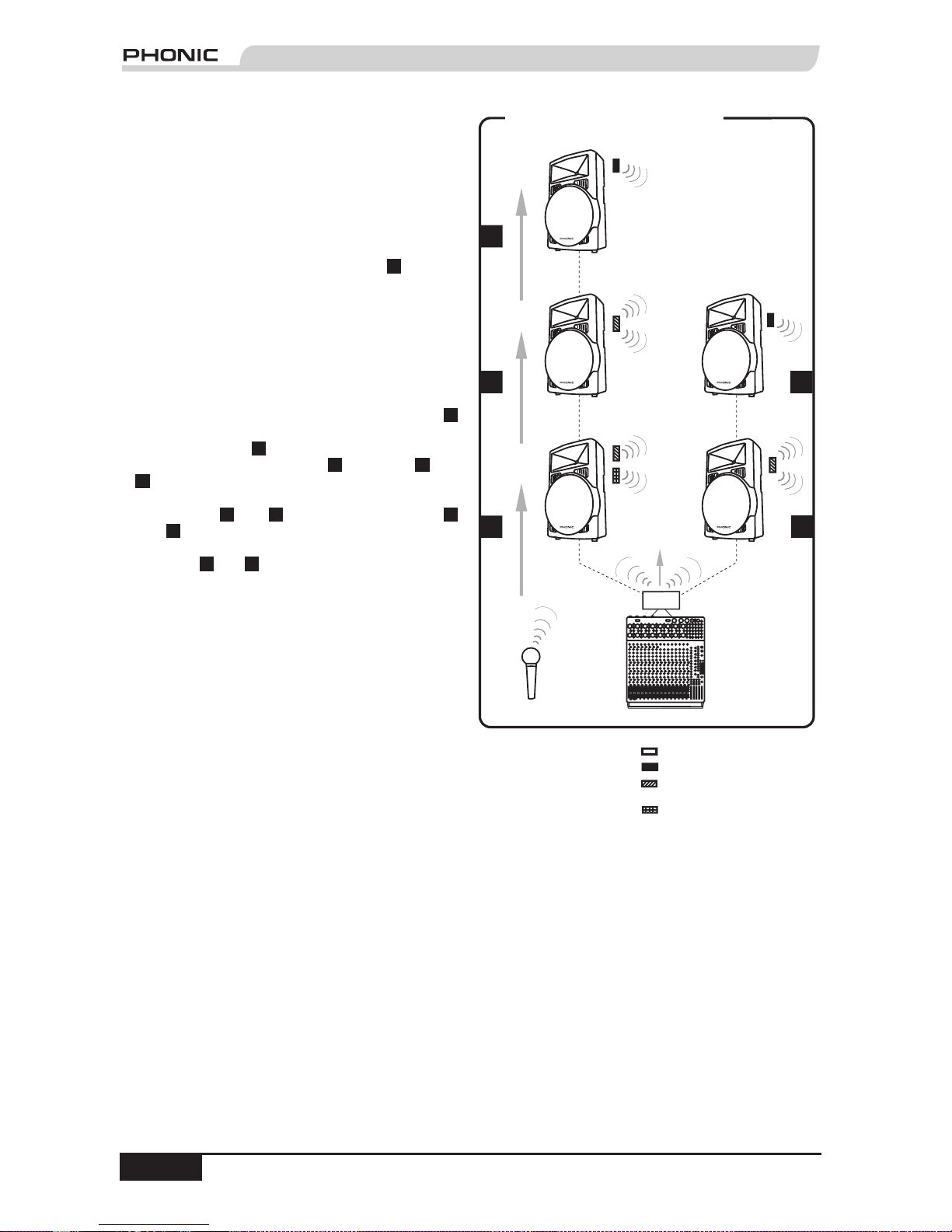
5) System Two (Stereo):
This conguration uses a Phonic wireless
microphone and mixer with Stand Alone Wireless
Transmitter Module (WM 60) transmitting the
source signals to ve "virtually" daisy chained
Performer active speakers. You can use a Phonic
VHF or UHF wireless microphone with wireless
module to transmit to the speakers. Set the
WIRELESS/WIRELESS MIC Switch in (down) on
the back of all the speakers. Speaker
1
has two
wireless modules installed in the two compartments
on the top of the speaker. One compartment is
tted with the matched-frequency wireless module
for the UHF or VHF wireless microphone. The
other compartment is tted with a Transmitter
& Receiver Module (WM 50) for receiving the
transmission from the Stand Alone Wireless
Transmitter Module (WM 60) and re-transmitting
it to the next speakers in the series. Speaker
1
re-transmits the VHF / UHF wireless microphone
signal to Speaker
2
, and the wireless microphone
and mixer signals to Speaker
3
. Speakers
2
and
3
both are tted with a Transmitter & Receiver
Module (WM 50) and they re-transmit the signals
to Speakers
4
and
5
, respectively. Speakers
4
and
5
each are tted with a Wireless Receiver
Module (WM 40) to receive the transmission from
Speakers
2
and
3
, respectively. This setup allows
all the speakers to instantly receive the wireless
microphone and mixer signals. You also are able to
play the mixer signals in stereo image because the
WM 60 auto-detects left- and right-side speakers.
(To install wireless modules please refer to the
instructions on page 15.)
Related Products: UM 11, UM 22, VM 11, VM 22,
WM 30, WM 40, WM 50, WM 60
VHF / UHF
Wireless Microphone
Mixer
L
R
Performer Speaker
SYSTEM TWO ( STEREO )
Performer Speaker
Performer Speaker
Performer Speaker
Performer Speaker
1
3
5
4
2
up to 100 feet
(30 meters)
up to 100 feet
(30 meters)
up to 100 feet
(30 meters)
up to 100 feet
(30 meters)
up to 100 feet
(30 meters)
WM60
2.4 GHz Transmitter (WM30)
2.4 GHz Receiver (WM400)
2.4 GHz Transmitter /
Receiver (WM50)
VHF / UHF Receiver
Page 13
PHONIC CORPORATION Performer User's Manual
page 13
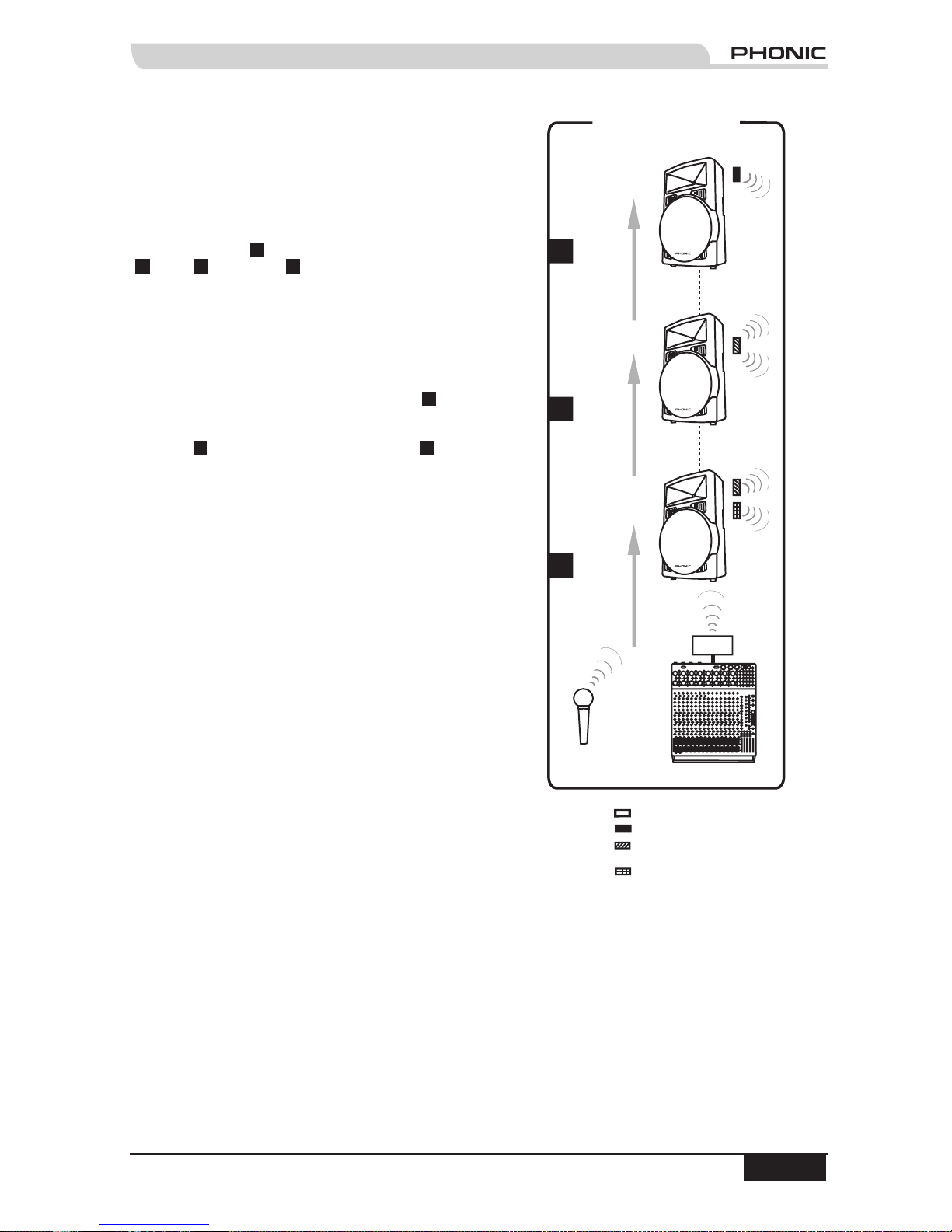
6) System Three (Mono):
This conguration uses a Phonic wireless microphone
and mixer with Stand Alone Wireless Transmitter
Module (WM 60) transmitting the source signals to three
"virtually" daisy chained Performer active speakers. You
can use a Phonic UHF or VHF wireless microphone
with wireless module to transmit to the speakers. Set
the WIRELESS/WIRELESS MIC Switch out (up) on the
back of Speaker
1
, and set it in (down) on Speakers
2
and
3
. Speaker
1
is tted with two wireless
modules installed in the two compartments on the top
of the speaker. One compartment has the matchedfrequency wireless module for the UHF or VHF wireless
microphone. The other compartment is tted with a
Transmitter & Receiver Module (WM 50) for receiving
the transmission from the Stand Alone Wireless
Transmitter Module (WM 60) and re-transmitting it to
the next speakers in the series. Speaker
2
is tted
with a Wireless Transmitter/Receiver Module (WM
50) for receiving the source signals transmission from
Speaker
1
and re-transmitting it to Speaker
3
, which is
tted with a Wireless Receiver Module (WM 40). In this
way you have a completely wireless system with all the
speakers receiving the same signals from the wireless
microphone and mixer. (To install wireless modules
please refer to the instructions on page 15.)
Related Products: UM 11, UM 22, VM 11, VM 22, WM
40, WM 50, WM 60
VHF / UHF
Wireless Microphone
Mixer
Performer Speaker
SYSTEM THREE
( MONO )
Performer Speaker
1
3
2
up to 100 feet
(30 meters)
up to 100 feet
(30 meters)
up to 100 feet
(30 meters)
up to 300
feet
(100 mete
rs)
WM60
Performer Speaker
2.4 GHz Transmitter (WM30)
2.4 GHz Receiver (WM400)
2.4 GHz Transmitter /
Receiver (WM50)
VHF / UHF Receiver
Page 14
Performer User's Manual PHONIC CORPORATION
page 14
PHONIC CORPORATION Performer User's Manual
page 15
7) System Four (Mono):
This conguration uses a dynamic microphone
or mixer wired to the rst of three "virtually" daisy
chained Performer active speakers. Set the
WIRELESS/WIRELESS MIC Switch in (down) on
the back of all the speakers. Speaker
1
is tted
with a Wireless Transmitter Module (WM 30) for
re-transmitting the microphone or mixer signal to
other wireless-enabled Performer active speakers.
Speaker
2
is tted with a Wireless Transmitter/
Receiver Module (WM 50) for receiving the
source signal transmission from Speaker
1
and
re-transmitting it to Speaker
3
, which is tted with
a Wireless Receiver Module (WM 40). (To install
wireless modules please refer to the instructions
on page 15.)
Related Products: WM 30, WM 40, WM 50
Performer Speaker
SYSTEM FOUR (MONO)
Performer Speaker
1
3
2
up to 100 feet
(30 meters)
up to 100 feet
(30 meters)
up to 100 feet
(30 meters)
Performer Speaker
Mixer
Dynamic
Microp
hone
2.4 GHz Transmitter (WM30)
2.4 GHz Receiver (WM400)
2.4 GHz Transmitter /
Receiver (WM50)
VHF / UHF Receiver
8) System Five (Stereo):
This conguration uses a mixer wired to the rst
left and right speakers of ve "virtually" daisy
chained Performer active speakers. Set the
WIRELESS/WIRELESS MIC Switch in (down) on
the back of all the speakers. Speakers
1
and
2
both are tted with a Wireless Transmitter Module
(WM 30) for re-transmitting the mixer signal to
other wireless-enabled Performer active speakers.
Speaker
3
is tted with a Transmitter & Receiver
Module (WM 50) to re-transmit the left channel
signal to Speaker
5
. Speakers
4
and
5
each are
tted with a Wireless Receiver Module (WM 40)
to receive the transmission from speakers
2
and
3
, respectively. (To install wireless modules
please refer to the instructions on page 15.)
Related Products: WM 30, WM 40, WM 50
Mixer
L
R
Performer Speaker
SYSTEM FIVE ( STEREO )
Performer Speaker
Performer Speaker
Performer Speaker
Performer Speaker
1
3
5
4
2
up to 100 feet
(30 meters)
up to 100 feet
(30 meters)
up to 100 feet
(30 meters)
Page 15
PHONIC CORPORATION Performer User's Manual
page 15
INSTALLING WIRELESS MODULES (optional accessories)
Phonic wireless modules are very easy to install and allow your Performer active speaker to receive signals
from Phonic matched-frequency wireless UHF and VHF microphones, 2.4 GHz wireless mixer transmitter
modules and 2.4 GHz wireless transmitter modules installed in other Performer active speakers.
Follow these directions to install or uninstall a wireless module:
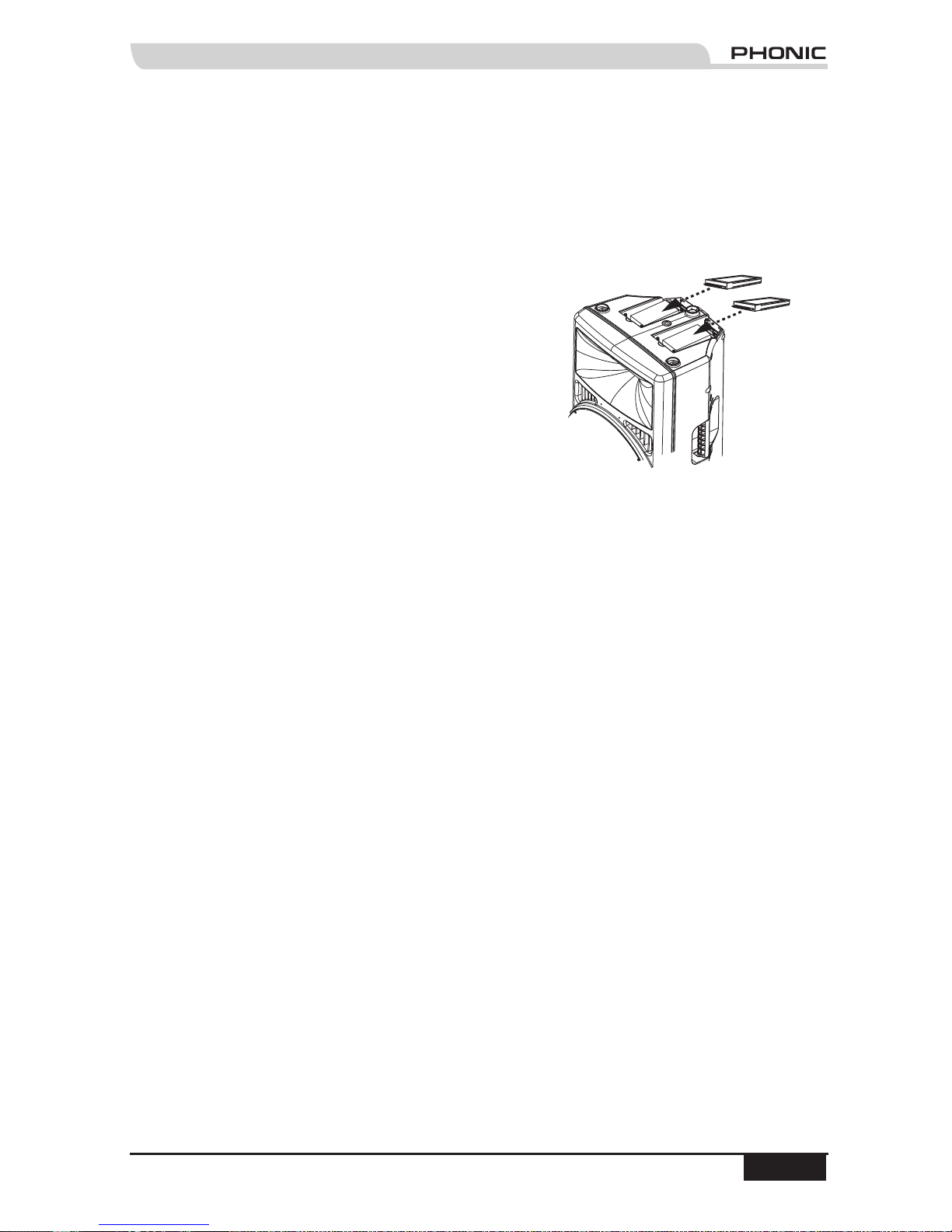
1. Locate the two wireless compartments on the top of the
Performer active speaker.
2. Using a Philips head screwdriver, remove one of the
compartment covers by removing the two screws that hold it
in place.
3. Insert the wireless module into the correct compartment. If you
are facing the back of the speaker, UHF and VHF wireless
modules should be installed in the compartment on the left,
and 2.4 GHZ wireless modules should be installed in the
compartment on the right. Make sure the wireless module is
right side up and that the card pins are lined up properly with
the pin receptors.
4. Replace the cover.
5. Replace the screws and tighten.
6. To uninstall wireless modules simply follow the above instructions, this time carefully removing the
wireless module from the compartment. Don’t forget to replace the compartment cover when you are
nished.
Note: Phonic can only ensure that our wireless modules will work according to specications, therefore only wireless
modules manufactured by Phonic should be used with Performer active speakers.
A
B
A: UHF/VHF Wireless Modules
B: 2.4 GHz Wireless Modules
Page 16

Performer User's Manual PHONIC CORPORATION
page 16
PHONIC CORPORATION Performer User's Manual
page 17
OPTIONAL ACCESSORIES
2.4 GHz Wireless Modules
One 2.4 GHz wireless module can be installed in the Performer active speaker. The Wireless Transmitter
Module (WM 30) can be used to wirelessly transmit the source signal to another speaker or speakers.
The Wireless Receiver Module (WM 40) will allow the Performer active speaker to receive source signal
transmissions, or those from another speaker. The Transmitter / Receiver Module (WM 50) can perform
the functions of both the WM 30 and the WM 40 at the same time. The Stand Alone Wireless Transmitter
Module (WM 60) can wirelessly transmit mono or stereo mixer signals to Performer active speakers. If stereo
transmission is selected, the WM 60 will auto-detect the left and right sides of the PA system and transmit the
signal in stereo image.
WM 30: Wireless Transmitter Module
WM 40: Wireless Receiver Module
WM 50: Wireless Transmitter / Receiver Module
WM 60: Stand Alone Wireless Transmitter Module
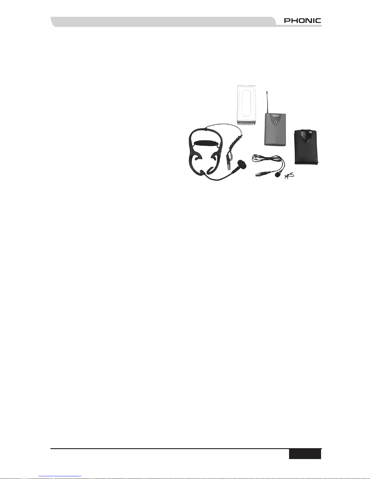
UHF/VHF Wireless Microphones with Modules
Performer active speakers have the option to install one UHF or VHF wireless module at one time. Phonic
UHF and VHF Handheld and Executive Systems come with a matched-frequency wireless module that can be
installed in the Performer active speaker, allowing it to wirelessly receive the signal.
UHF
UM 11: Wireless UHF Handheld System
UM 22: Wireless UHF Executive System
VHF
VM 11: Wireless VHF Handheld System
VM 22: Wireless VHF Executive System
Speaker Stands
SK1: Two speaker stands and carry bag
SK2: Two speaker stands, two Mic stands and carry bag
Page 17
PHONIC CORPORATION Performer User's Manual
page 17
PURCHASING OPTIONAL ACCESSORIES
To purchase Phonic gear and optional accessories, please contact an authorized Phonic distributor. For a list
of nearby Phonic distributors please visit our website at www.phonic.com and click Get Gear. You may also
contact Phonic directly and we will assist you in locating a distributor:
Phonic
5411 Johns Road, #605
Tampa, FL 33634
(813) 890-8872
SERVICE AND REPAIR
Phonic has over 100 service centers worldwide.
Please contact an authorized Phonic distributor
for service and repairs. For a list of nearby
Phonic distributors please visit our website at
www.phonic.com and click Get Gear.
CUSTOMER SERVICE AND TECHNICAL SUPPORT
We encourage you to visit our website at www.phonic.com. There you can browse our FAQs found on our
Support page. Your questions may already be answered there. If not, email us, and we will get back to you
within 24 hours.
U.S. inquiries please e-mail us at:
[email protected]
International inquiries please e-mail us at:
[email protected]
Page 18
Performer User's Manual PHONIC CORPORATION
page 18
PHONIC CORPORATION Performer User's Manual
page 19
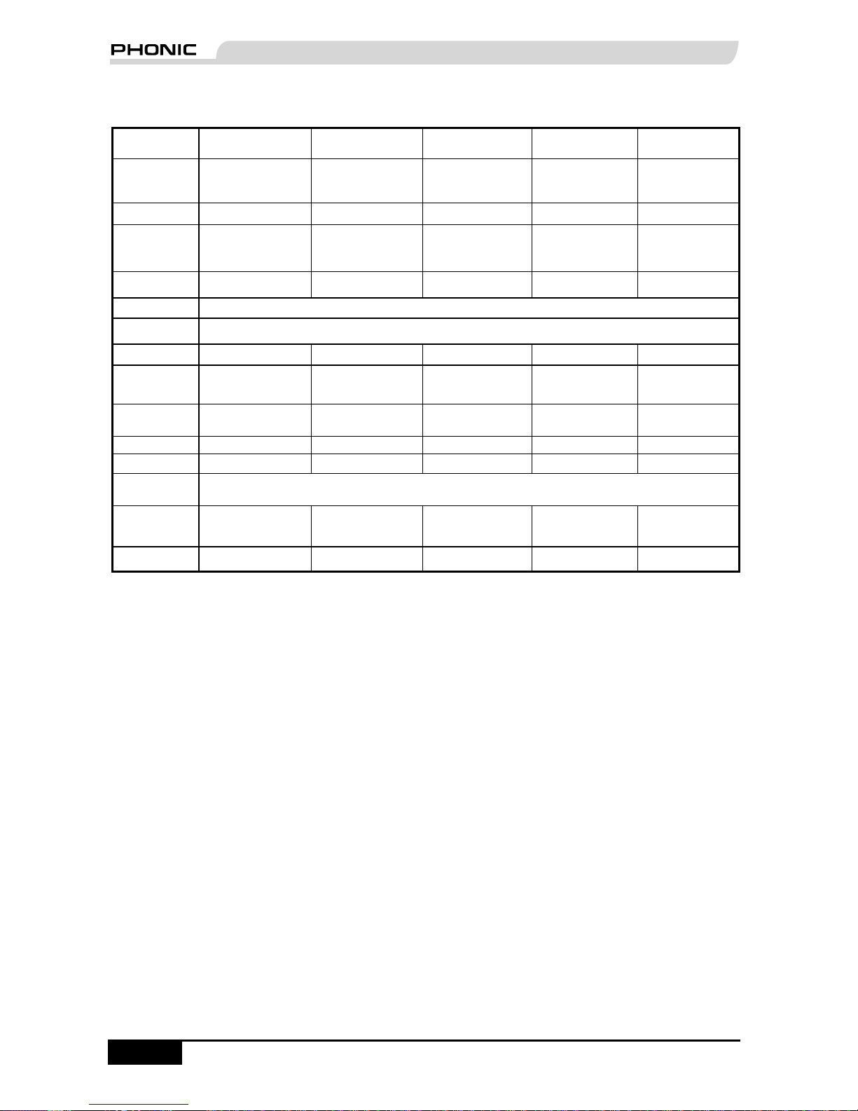
SPECIFICATIONS
PERFORMER
A210
PERFORMER
A220
PERFORMER
A230
PERFORMER
A520
PERFORMER
A530
Type
Wireless 12” 90W
Active Speaker
Wireless 12” 160W
Active Speaker
Wireless 12” 275W
Active Speaker
Wireless 15” 160W
Active Speaker
Wireless 15” 275W
Active Speaker
Output RMS 70W + 20W 120W + 40W 225W + 50W 120W + 40W 225W + 50W
Frequency
Response
65Hz - 20KHz 65Hz - 20KHz 65Hz - 20KHz 50Hz - 20KHz 50Hz - 20KHz
Max SPL @1M 120 dB 123 dB 126 dB 123 dB 126 dB
Impedance 20 k ohms balanced / 10 k ohms unbalanced
Sensitive -50 - 0 dB on input
Bass Drive 12” 12” 12” 15” 15”
Tweeter
Diaphragm
1” 1” 1” 1” 1”
Dispersion
Angle
90° x 60° 90° x 60° 90° x 60° 90° x 60° 90° x 60°
Input XLR+ TRS 1/4” XLR+ TRS 1/4” XLR+ TRS 1/4” XLR+ TRS 1/4” XLR+ TRS 1/4”
Link Output XLR XLR XLR XLR XLR
Enclosure
Design
Molded Polypropylene Asymmetrical Trapezoidal
Dimensions
(H x W x D)
693 x 442 x 342mm
(27.3"x17.4"x13.5")
693 x 442 x 342mm
(27.3"x17.4"x13.5")
693 x 442 x 342mm
(27.3"x17.4"x13.5")
693 x 442 x 342mm
(27.3"x17.4"x13.5")
693 x 442 x 342mm
(27.3"x17.4"x13.5")
Weight 18 kg 19 kg 20.5 kg 19.5 kg 21.5 kg
Page 19
PHONIC CORPORATION Performer User's Manual
page 19
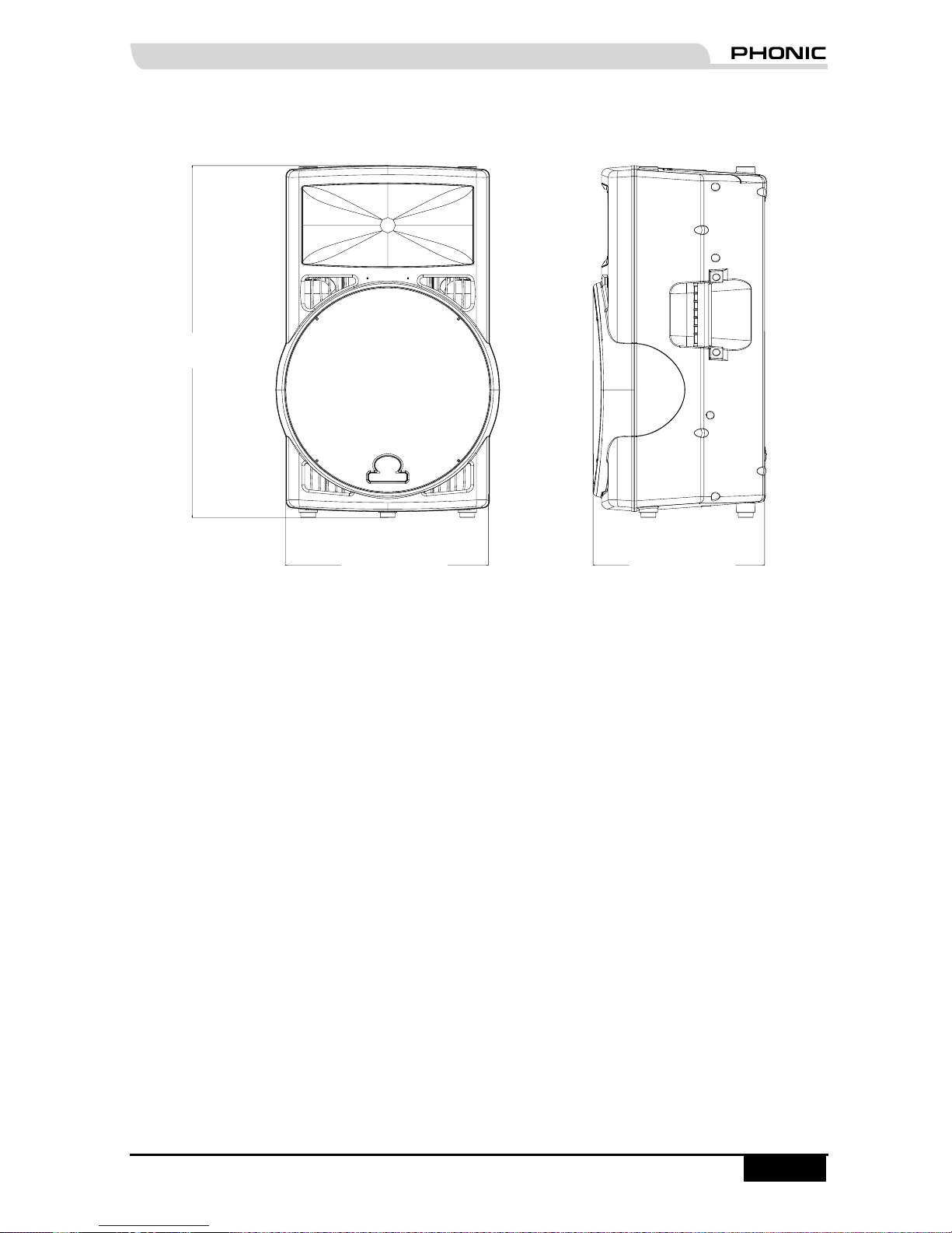
DIMENSIONS
Measurements are shown in mm/inch
Page 20

 Loading...