

Page 1

Page 2

SAFTY PRECAUTIONS
SAFETY PRECAUTIONS!
WARNING - TO REDUCE THE RISK OF FIRE OR ELECTRIC SHOCK, DO NOT
EXPOSE THIS UNIT TO RAIN OR MOISTURE.
Do not allow water or liquids to be spilled into this unit. If the unit has been exposed to rain or liquids,
please unplug the power cord immediately from the outlet (with DRY HANDS) and get a qualified service
technician to check it. Keep this unit away from heat sources such as radiators, heat registers, stoves, etc.
This unit contains no user-serviceable parts. Refer all service needs to a qualified
service engineer through a Phonic dealer.
This triangle on your component alerts you
to the presence of uninsulated “ dangerous
voltage” inside the enclosure that may be
sufficient to constitute a risk of shock.
This triangle on your component alerts you
to important operating and maintenance instructions in this accompanying literature.
CAUTION:
TO REDUCE THE RISK OF ELECTRIC SHOCK, DO NOT REMOVE COVERS (OR
BACK). NO USER-SERVICEABLE PARTS ARE INSIDE. REFER ALL SERVICING
TO A QUALIFIED SERVICE PERSONNEL.
Keep this unit clean by using a soft dry brush and occasionally wiping it with a damp cloth. Do not use any
other solvents, which may damage the paint or plastic parts. Regular care and inspection will be rewarded
by a long life and maximum reliability.
Your Phonic MM1002 / MM1202 was carefully packed at the manufacturing site and the packing box was
designed to protect the unit from rough handling. We recommend that you carefully examine the packaging
and its contents for any signs of physical damage, which may have occurred during transportation.
If the unit is damaged:
for damage or replacement may not be granted if not reported properly or in a timely manner.
Notify your dealer and the shipping company immediately. Claims
PHONIC CORPORATIONMM1002 / MM1202 USER’S MANUALPage 2
Page 3

CONTENTS
INTRODUCTION............................................4
FEATURES...............................................4
GETTING STARTED.......................................4
CONNECTING IT UP.................................5
TYPICAL CONNECTING LEADS.....................6
UNBALANCED & BALANCED.........................7
CHANNEL STRIP DESCRIPTION.....................8
MIC/LINE MM1002(CH1~2)/MM1202(CH1~4).......8
GAIN...........................................................8
EQUALIZER..................................................8
AUX ................................................................9
EFX(MM1202 ONLY)......................................9
PEAK...................................................9
PAN...........................................................9
LEVEL.................................................10
M-S SWITCH........................................10
M-S STEREO RECORDING..........................10
WHA T IS A CARDIOID MICROPHONE?.............1 1
WHA T IS A FIGURE-8 MICROPHONE?.............11
STEREO INPUT.................................................12
+4/-10 SWITCH..........................................12
BAL(BALANCE)CONTROL...........................12
MASTER SECTION DESCRIPTION...............13
MAIN OUT......................................13
EFX OUT(MM1202 ONY)..............................13
AUX OUT...........................................13
CTRL RM...................................13
REC................................................13
2T RTN......................................................13
EFX OUT CONTROL(MM1202 ONL Y)............13
AUX OUT CONTROL(MM1202 ONL Y)...........13
+48V PHANTOM PWR..............................13
LED LEVEL METERS..................................13
HEADPHONE/STEREO INDICATION
SELECT BUTTON.......................................13
MS/ST SELECT BUTTON...........................13
2T RTN SIGNAL P A TH SELECT BUTTON.....13
AUX SIGNAL P ATH SELECT BUTT ON..........14
CTRL RM LEVEL...................................14
HEADPHONE.....................................14
MAIN L/R FADER..............................14
REAR PANEL DESCRIPTION...............14
POWER SUPPLY INPUT SOCKET..............14
POWER ON/OFF SWITCH..........................14
INITIAL SETUP...........................................15
APPLICATIONS.....................................16
STANDARD CONNECTIONS...................16
LIVE BAND SETTING............................17
DIMENSIONS ............................................18
SPECIFICATIONS.....................................19
SYSTEM BLOCK DIAGRAMS.....................21
REFERENCE BOOKS..................................22
PHONIC CORPORATION MM1002 / MM1202 USER’S MANUAL Page 3
Page 4

INTRODUCTION / FEA TURES / GETTING STARTED
INTRODUCTION
Congratulations on your purchase of the MM serial
Mixer. The MM serial mixer is built into a rugged
construction, which is ideal for small live gigs, recording and fixed PA installations. In order to get
the best performance from the mixer, please read
this user’s manual carefully. Please familiarize yourself with the new and different functions on this mixer.
FEATURES
MM1002
l 10 standard inputs
l 2 balanced Mic/Line input channels with 2 band
EQ. Able to accept a wide range of Microphone
and Line level from Neutrik combo connector
l 4 stereo inputs with +4/-10 input sensitivity se-
lector
l Additional 2T return inputs, for CD playback or
link to submixer
l Global +48V phantom power switch on 1-2 chan-
nel at master section
l Separate Mix and Control Room output
l M/S switch
l Record output
l Meter indicator switch allows meter to show MS/
ST/Headphone level
l Headphone output
l Peak indicators on each mono input channel
MM1202
l 12 standard inputs
l 4-balanced Mic/Line input channels with 3 band
EQ. Able to accept a wide range of Microphone
and Line level from Neutrik combo connector
l 4 stereo inputs with +4/-10 input sensitivity
selector.
l Additional 2T return inputs, for CD playback or
link to another submixer
l Global +48V phantom power switch on 1-4
channel at master section
l Separate Mix and Control Room output
l M/S switch
l Record output
l Meter indicator switch allows meter to show MS/
ST/Headphone level
l Headphone output
l Peak indicators on each mono input channel
GETTING STARTED
1. Check the AC voltage before connecting the AC
plug. This product is equipped with a 3-wire
grounding type plug; this is a safety feature and
should not be defeated. Proper grounding is a
necessary practice to prevent electric shock
hazards to the operator, the microphone user,
and the musicians who are wired to this unit.
2. Before switching on the main power, keep all the
output fader all the way down to prevent damage
or excessive noise caused by bad level
adjustment, wrong wiring, defective cables, or bad
connection.
3. Always turn on the mixer before the power
amplifier; turn off the mixer after the amplifier.
4. Always turn off the unit before connecting and
disconnecting the unit from the power source.
5. Never use solvents to clean the unit. Clean with
a soft, dry cloth.
PHONIC CORPORATIONMM1002 / MM1202 USER’S MANUALPage 4
Page 5
CONNECTING IT UP
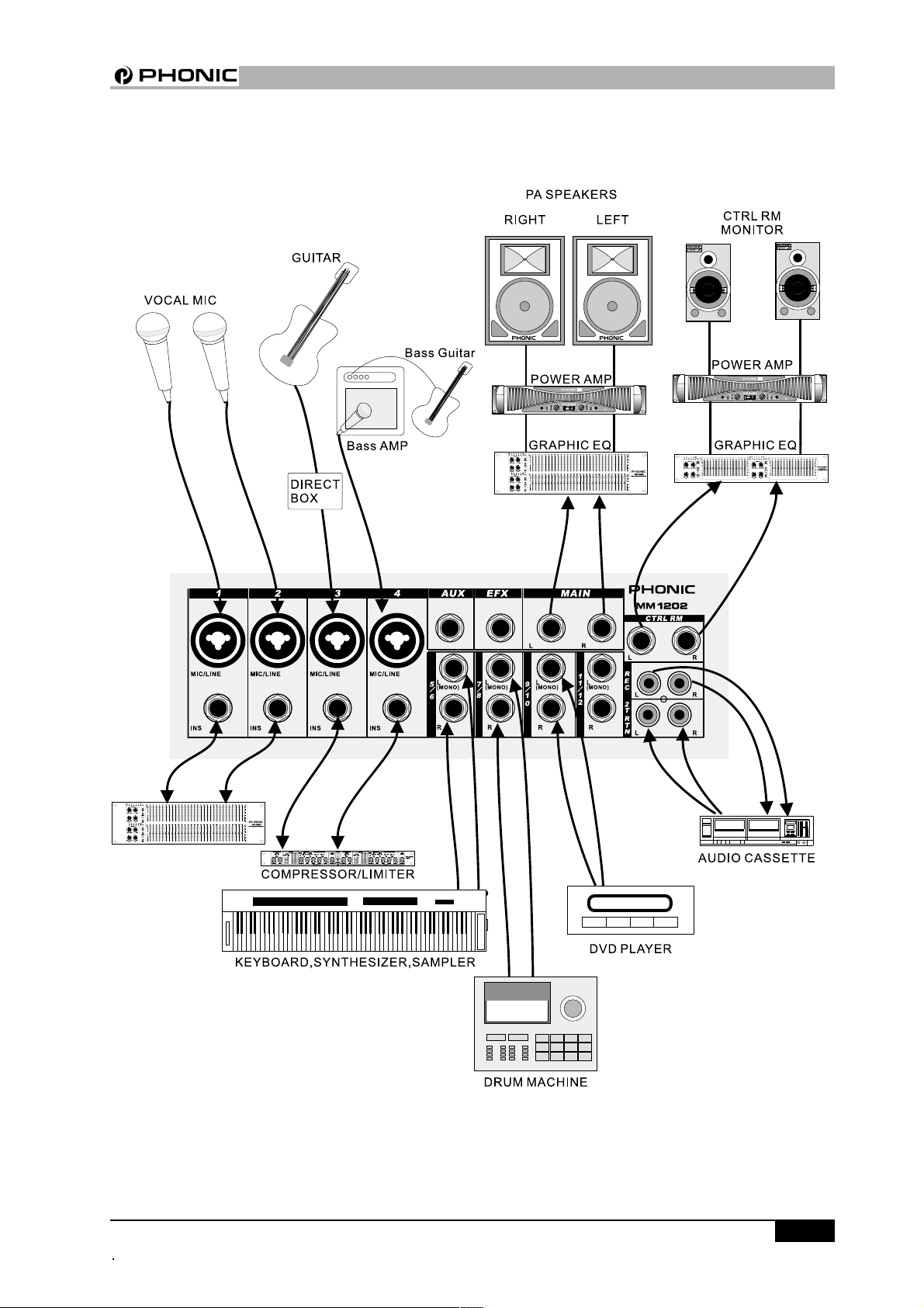
CONNECTING IT UP
PHONIC CORPORA TION MM1002 / MM1202 USER’S MANUAL Page 5
Page 6
TYPICAL CONNECTING LEADS
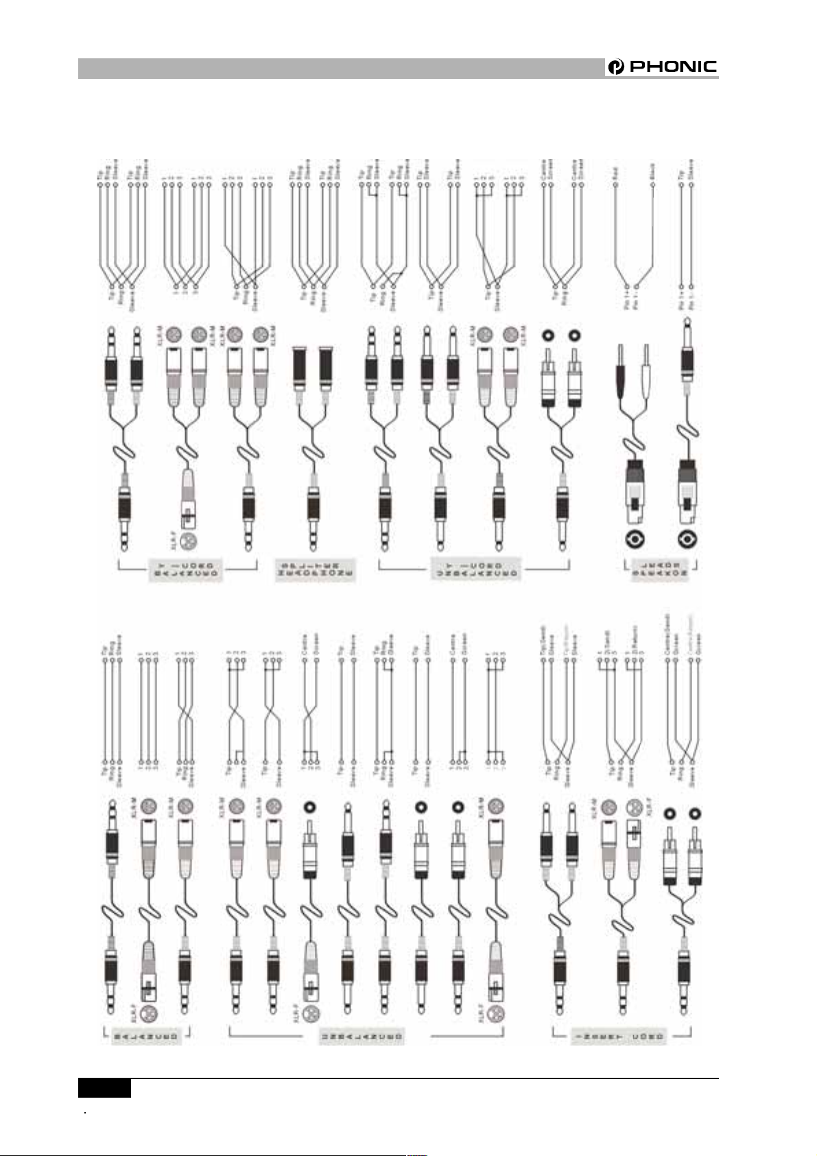
TYPICAL CONNECTING LEADS
PHONIC CORPORATIONMM1002 / MM1202 USER’S MANUALPage 6
Page 7

UNBALANCED & BALANCED
UNBALANCED & BALANCED
Most of the mistakes in audio installations are due
to incorrect and defective audio connections. In order to perfectly complete your installation. Please
pay special attention to the following section unless
you are already familiar with balanced/unbalanced
operations.
WHA T IS AN UNBALANCED LINE?
You can find this kind of system in most of home
audio-video systems. They have one conductor to
carry signal, and another conductor for a ground.
Normally, for lower level signals, the ground conductor shields the signal conductor.
WHA T IS A BALANCED LINE?
A balanced system transmits signal via 2 conductors plus one ground shielding conductor. The 2 signal conductors carry the same signal but out of phase.
For the balanced input stage, the amplifier will boost
the difference between the 2 signal conductors and
remove the identical part (known as common mode
signal) of the 2 signals . Because the real signal is
carried by the 2 conductors out of phase, so it is
perfectly carried to the input. At the same time, interference that occurs during transmission will be
identical (common mode). Because the signal conductors are run together, there is no chance they
can be different, and all the interference will be removed by the balanced input amplifier.
THE DIFFERENCE BETWEEN TWO
OPERA TIONS:
Because of the common mode interference immunity of a balanced system, the ground conductor
doesn’t need to carry any electrical current, which
means the ground of the 2 connected units has an
identical ground level which is vital to an interference free system. Let’s look back at the unbalanced
system. The signal electrical current goes from the
signal conductor to the ground conductor. The ground
level of the 2 connected units are not identical. This
means the system is more easily inclined to noise
interference.
Running long cables is easy for a balanced system
but difficult for an unbalanced system. A Lower noise
level is a characteristic of a balanced system.
Because a balanced system needs 2 conductors for
the signal and 1 conductor for the ground, a minimum of 3 conductors are needed for wiring a balanced system. So a dedicated system separates the
ground and shields the 2 conductors.
Please read following section to properly wire for balanced and unbalanced systems:
THE CORRECT WIRING FOR BALANCED
OPERA TION:
Always connect the main power with 3 plugs. Make
sure the power system ground is working properly.
Don’t use a ground insulator plug adapter without properly connecting the ground individually. This is vital to
making a successful audio system connection.
Always connect the ground pin (PIN 1 in XLR) to the
source unit, and disconnect this pin on the destination unit. This connection topology is to avoid creating a grounding loop between the signal and power
ground. Utilize only the power ground, because it
always has a lower resistance and better distribution
than the signal ground.
If there is hum, a possible reason is a bad ground
connection for the system. In case you can not find
the fault, try connecting the ground pin of the input
connectors. If the hum is reduced or eliminated, check
your power grounding system. Special attention is
needed when you use the equipment racks with some
distance between them, and/or use a large quantity
of power amplifiers. Check the power ground between
the racks and power distribution strips with your electrical supply engineer. Make sure there is one, and
only one, proper ground point for the audio system
(or connected video system).
PHONIC CORPORATION Page 7
MM1002 / MM1020 USER’S MANUAL
Page 8
CHANNEL STRIP DESCRIPTION
CHANNEL STRIP DESCRIPRION
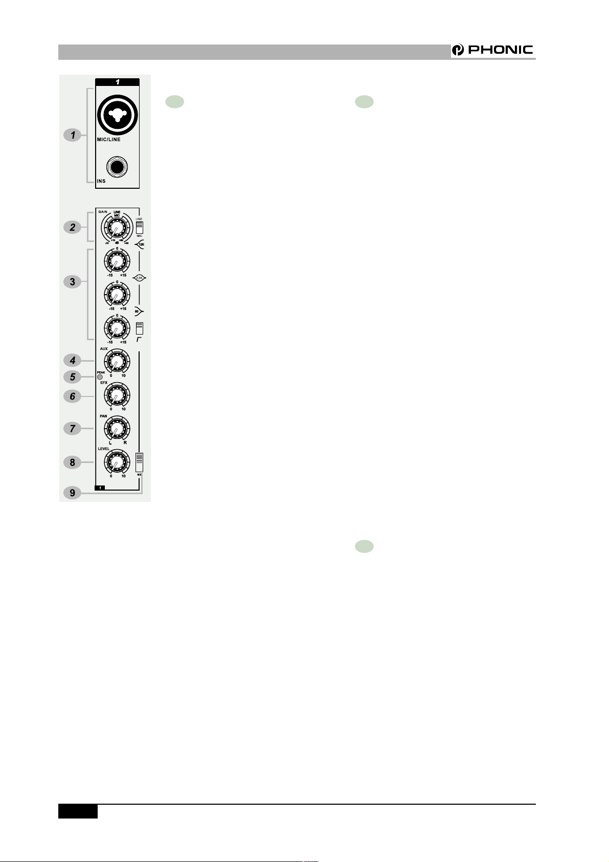
1 MIC/LINE MM1002(Ch1~2)/
MM1202 (Ch1~4)
The Microphone is via a combo connector,
which allows the connections of XLR or
1/4 “ type phone jack. Please use only
professional low impedance microphone
and properly wired cable for best result.
When the 1/4“ phone jack plug into the
combo connector, the connection can be
microphone or line level signal, we can
change the input trim for MIC or LINE by
using the LINE/MIC slide-switch to set
the different TRIM accordingly. However,
the phantom power is only available for
the XLR connection. Never turn on the
phantom power when you have line level
source connected to the XLR connector.
48V PHANTOM POWER
+48V Phantom Power is available on
each microphone input channel. All
faders should be all the way down
when switching on/off the phantom
power, in order to prevent excessive
noise to stage monitor speakers and
main speakers; Phantom powered
mics should not be plugged in with
the +48V switched on.
2 GAIN
This rotary knob adjusts the channel signal level. Too high, the signal will distort
as it overloads the channel. Too low, the
level of back hiss will be more noticeable
and there might be insufficient signal level
to the output of the mixer. Proper gain
setting allows the mixer to work in the
best operating level, adjusts the gain when
signal presents to the highest level without triggering the peak LED. That is the
most appropriate position.
This gain has two kinds of indication to
suit mic or line input, when you use mic
input, please read inside ring from
+10~+60 dB, if you use line input, please
read outside ring from -10~+40dB.
LINE / MIC SWITCH
When you use the channel for
microphone, either through XLR or Phone
plug, please switch to MIC. If you use
the channel for line level source, either
through XLR or Phone plug, please switch
to the LINE. This switch will set the appropriate gain range for the input signal.
INS
The INSERT is a break point in the input
channel signal path. It allows the signal
to be taken out from the mixer, through
an external equipment such as a
compressor, and then back to the mixer
to continue the final mix output.
3 EQUALIZER
HIGH
Turn right to boost high frequency, add-
ing crispness to cymbals, vocals and
electronic instruments. Turn left to cut this
frequency, reducing sibilance or hiss. The
control has a shelving response that gives
15dB of boost or cut at 12KHZ.
PHONIC CORPORATIONMM1002 / MM1202 USER’S MANUALPage 8
Page 9

CHANNEL STRIP DESCRIPTION
MID (MM1202 ONL Y)
The knob provides 15dB of boost or cut
at 2.5KHz, just like the HF EQ knob, the
mid band covers the range of most vocals.
Listen carefully when you use this control to find how particular characteristics
of vocal or guitar signal can be enhanced
or reduced .Set the upper knob in the “0”
position when not required.
LOW
The control has shelving response that
gives 15dB of boost or cut at 80Hz. Adding warmth to vocals or extra punch to
guitars, drums and synths by turning to
the right. Turn left to reduce stage rumble,
hum or to improve a mushy sound.
These equalizers are designed to
accomodate different room acoustics,
feedback control and improve live PA
sound. But no amount of equalization will
correct the frequency response curve of
a poor loudspeaker. Always begin with
all control at the “0” position and avoid
excessively cutting/boosting large segments of the peculiar frequency, which
would limit the system dynamic range or
increase the possibility of the unpleasant feedback sound.T o make sound more
impressive, dynamic process is
necessary. Channel inserts are designed
to add-on a compressor, limiter or gate.
Please refer to Phonic PCL3200 or
MCL2000 for further information.
4 AUX
This rotary fader sends out the channel
signal to AUX bus. The signal is pre-fader
so that the aux send to be independent
of the fader; this is suitable for foldback
or monitor.
5 EFX (MM1202 ONL Y)
This rotary fader feeds the channel signal to the external effect. The signal is
post fader. This is very helpful in simultaneously adjusting the level of the pro-
cessed signal.
6 PEAK
This red LED will warn you when an excessively high signal level is present in
the channel. The signal is sampled at two
points in the channel, immediately after/
before the HPF and equalizer. The peak
LED will illuminate approximately 6dB
before clipping and therefore give warning of a possible overload.
7 P AN
This control sets the amount of the channel signal feeding the left and right mix
bus, allows you to locate the source
smoothly across the stereo image.
LOW CUT
Slide down the slide-switch; insert the
18dB per octave 75Hz low cut filter in the
signal path. This low cut filter is useful on
live vocals to reduce stage rumble or ‘pop-
ping’ from microphones. It can also be
used to cut off low frequency hum.
PHONIC CORPORATION MM1002 / MM1202 USER’S MANUAL Page 9
Page 10

CHANNEL STRIP DESCRIPTION
8 LEVEL
A rotary fader determines the proportion
of the channel in the mix and provides a
clear visual indication of channel level.
9 M-S SWITCH
To create your stereo sound image, simply slide the switcher to MS and you get
a M-S stereo recording.
If you want to make a M-S stereo
recording, usually, you will need 2
microphones, one is cardioid for M signal pointing at the center, and the other
is figure-eight microphone for S signal
pointing to the side. In order to decode
the MS signal to XY, you need 3 channels of Mic input to start with, one for M
and the other two for +S and -S
accordingly. MM series’ unique feature the MS switch - will help simplify the whole
process. Now you will not have to worry
about the channel availability, and patching with a special cable. When you have
an occasion to make a stereo recording,
please just choose the MM series mixer
and simply slide the M-S switch down.
The mixer will prepare everything itself.
The odd channel will now become the M
channel. The even channel will become
the S channel-just plug and play.
facing sideways. The figure-eight microphone picks up the left half of the source
with one phase and the right half with the
inverted phase. When the signal is added
to the signal from the cardioid, the signals from the left side are added together,
while the signal from the right subtract
due to the phase inversion. The combined
pattern of the two microphones is similar
to two cardioids (or figure eight) facing 45
degrees to the left and the other cardiod
facing 45 degrees to the right to create
the stereo image. Why don’t we use two
cardioids 90 degrees apart? That will do
something entirely different! With the MS system, the related angle of the
cardioids can be varied according to the
level of S (figure eight), and this will vary
the width of the stereo image.
M-S STEREO RECORDING
M-S is an abbreviation for mid-side, the
microphones used for M-S recording are
a cardioid microphone facing directly to
the source, and a figure-eight microphone
MM1002 / MM1202 USER’S MANUAL
PHONIC CORPORA TIONPage 10
Page 11

WHA T IS A CARDIOID MICROPHONE?
Cardioid means heart-shaped. Any microphone which
has a hearted-shaped Polar Pattern is called a cardioid microphone. The cardioid is most sensitive to
the sounds which arrive from the front. The sounds
which arrive from 90 degrees to the side are 6 Decibels less sensitive than to the front, and theoretically,
it is completely insensitive to the sounds coming
from the rear. In practice, the 100% directional qualities of a cardioid are impossible to achieve due to
reflected sounds from walls and ceiling, which are
entering the sensitive area of the microphone.
The most important attribute of the cardioid is that
the microphone can discriminate between direct
sounds and reverberant sounds, which come from
all other directions at random. One of the most important uses of the cardioid microphone is in sound
reinforcement, where the directivitive allows the system gain to be higher without generating acoustic
feedback.
CHANNEL STRIP DESCRIPTION
CARDIOID POLAR PATTERN
WHA T IS A FIGURE-8 MICROPHONE?
The derivation of the name for this pattern is obvious
from the following figure. Bi-directional elements are
most sensitive to sounds coming in from the front or
rear( left or right) of the microphone, and reject sounds
from the sides( front and rear).
FIGURE-8 POLAR PATTERN
PHONIC CORPORATION Page 1 1
MM1002 / MM1202 USER’S MANUAL
Page 12

CHANNEL STRIP DESCRIPTION
10 STEREO INPUT
These high impedance inputs accept 2-pole phone jacks. Use these
inputs for keyboards, drum
machines, synths, tape machine or
processing units. If the source signal is mono please plugs into the
left channel socket only.
11 +4/-10 SWITCH
The stereo input channel accept 1/
4“ phone jacks. It provides two input sensitivities .The –10dBV
should be selected for amateur type
machine or HIFI systems, most
professional equipment uses input
and output levels of +4dBu. This
switch allows you to match the
sources connected to the stereo
input channel to either standard,
which is important to ensure the
best possible sound quality, start
with the switch +4, if you can‘t
achieve an enough signal level, select to –10dBV.
12 BAL (BALANCE) CONTROL
The BALANCE control sets the
amount of the channel signal feeding the MAIN mix output, allows
you to balance the source in the
stereo image. When the control
knob turns fully to the left or right,
you send only that side of the signal to the mix.
PHONIC CORPORATIONPage 12 MM1002 / MM1202 USER’S MANUAL
Page 13

MASTER SECTION DESCRIPTION
MASTER SECTION DESCRIPTION
13 MAIN OUT
These sockets send line level signals
from the mixer to external devices (for
example: EQ or a power amplifier).
14 EFX OUT (MM1202 only)
This socket sends out the signals from
mix bus.
15 AUX OUT
This socket sends out the signals from
aux bus.
16 CTRL RM
This jack socket sends the mix signals to the control room speakers.
17 REC
The signals are sent to the tape recorder via the associate RCA sockets.
18 2T RTN
These 2 RCA jacks are for the 2T tape
return to the mixer.
19 EFX OUT CONTROL(MM1202
ONL Y)
22 LED LEVEL METERS
LED meter shows the level of master mix L and R in the stereo mode:
In the MS mode, the left hand side
meter shows the M signal level, the
right hand side shows the S signal
level.
23 HEADPHONE / STEREO INDICA TION SELECT BUTTON
Push down to select the meter to
show headphone level, release it to
show the main stereo output level.
24 MS/ST SELECT BUTTON
The switch select the LED LEVEL
METER are in the MS or STEREO
mode, in the MS mode; the left
channel of the LED LEVEL METER
represents the M signal, the right
channel of the LED LEVEL METER
represents the S signal. Two LED
level are always different. The
closer the difference between two
levels the wider the stereo image
you can get. If only the M signal of
the meter shows, the master output is MONO. If S level is higher
than M, the stereo is out of phase.
This knob controls the mix signals level
send to the external effect.
20 AUX OUT CONTROL(MM1202
ONL Y)
This knob controls the AUX OUT level.
21 +48V PHANTOM PWR
This slide-switch turns the master
phantom power on and off.
PHONIC CORPORATION
25 2T RTN SIGNAL PATH SELECT BUTTON
Push down the right button feeds
the 2T RTN signals into MAIN L/R
output. Push down the left button
feeds the 2T RTN signals into control room and effected by the control room level.
Page 13MM1002 / MM1202 USER’S MANUAL
Page 14

REAR P ANEL DESCRIPTION
26 AUX SIGNAL PATH SELECT
BUTTON
Push this button to feed the AUX signal to the control room affected by the
control room level.
27 CTRL RM LEVEL
This rotary fader controls the output
level to the control room and
headphone.
28 HEADPHONE
This jack socket sends the mix signals to the headphone.
29 MAIN L/R FADER
This 60mm long fader controls the
output level of MAIN OUT.
REAR PANEL DESCRIPTION
30 POWER SUPPLY INPUT
SOCKET
Connect the power supply unit to this
socket. Make sure the power supply
unit is not plugged into AC outlet before connecting to the mixer.
31 POWER ON/OFF SWITCH
This switch turns the power of the unit
on and off.
Page 14
MM1002 / MM1202 USER’S MANUAL
PHONIC CORPORATION
Page 15

INITIAL SET UP
INITIAL SETUP
This procedure is very important. Even if you don’t
like to read manuals, please read this section. After you have connected the system, you can begin
the initial set up for every input channel. The matching of every input gain to the signal source is crucial.
Every detail affects the final output of the mixer.
Basically, the input sensitivity adjustment, channel fader, and output fader are the main factors.
You should try to set only as much microphone
gain as required to achieve a good balance between
signals. If the input gain is set too low, you will not
get enough gain on the faders to push the signal up
to an adequate level. If the input gain is set too
high, the channel fader will need to be pulled down
in compensation, but leave the greater risk of feedback because a small fader movements will have a
very significant effect on output level. Certainly, the
limited fader travel path will not be successful in
the mixing procedure. Please use the following set
up procedure. Don’t turn the output up until they
clip and then backing off.
you can listen to them through your headphone.
l For”+4” line level audio signals, slide the +4/-10
switch to +4.
l For “-10” sources, slide the +4/-10 switch to -10.
l For microphone sources, the gain control adjust-
ment will depend on what kind of the microphone
you use, normally turn the gain clockwise around
2~3 o’clock. But please ask the singer to perform outloud, don’t whisper, if they do not sing at
a normal level while you are doing the sound check,
you might drive the mixer to overload or produce
feedback, because you set the gain too high during the initial set up.
l Repeat this procedure on all other channels. When
more channels are added to the mixer, the meters
LED may move up to the red section. Adjust the
overall level using the master faders if necessary.
FOLLOW THE PROCEDURE FOR EACH
CHANNEL IN USE
l Set all faders and gain controls all the way off.
l Phantom powered microphone should be con-
nected before the +48V is switched on.
l Set power amplifier levels to 70%.
l Set the CTRL RM Level and Headphone level to
about 50%.
l If you want to hear what you’re doing later, plug
your headphone into the phone output socket,
or hook up your control room amplifier system
to the Control Room outputs.
l Set EQ control at center position.
l Set P AN and BALANCE knobs at center position.
l Y ou need a headphone to continue.
l Apply a typical performance level signal, moni-
toring the level on the LED meter.
l Adjust the input gain until the meter shows in
the amber section, with occasional peaks to the
first red LED at maximum source level. This allows enough headroom to accommodate peaks
and the maximum level for normal operation;
PHONIC CORPORATION Page 15
MM1002 / MM1202 USER’S MANUAL
Page 16

APPLICA TIONS
APPLICATIONS
ST ANDARD CONNECTIONS
MM1002 / MM1202 USER’S MANUAL
PHONIC CORPORATIONPage 16
Page 17

LIVE BAND SETTING
APPLICA TIONS
PHONIC CORPORATION Page 17
MM1002 / MM1202 USER’S MANUAL
Page 18

DIMENSIONS
DIMENSIONS
MM1002
MM1202
Measurements are shown in mm/inch.
MM1002 / MM1202 USER’S MANUAL
PHONIC CORPORATIONPage 18
Page 19

SPECIFICATIONS
SPECIFICA TIONS
PHONIC CORPORATION Page19
MM1002 / MM1202 USER’S MANUAL
Page 20

SPECIFICA TIONS
Due to continuous product improvement, the specifications are subject to change without notice.
MM1002 / MM1202 USER’S MANUAL
PHONIC CORPORATIONPage 20
Page 21

SYSTEM BLOCK DIAGRAMS
MM1002
SYSTEM BLOCK DIAGRAMS
PHONIC CORPORATION Page 21
MM1002 / MM1202 USER’S MANUAL
Page 22

SYSTEM BLOCK DIAGRAMS
MM1202
Page 22
PHONIC CORPORA TIONMM1002 / MM1202 USER’S MANUAL
Page 23

REFERENCE BOOKS
Phonic recommends the following books for those
interested in advanced audio engineering and sound
system operation:
l Sound System Engineering by Don and Carolyn
Davis, Focal Press, ISBN: 0-240-80305-1
l Sound Reinforcement Handbook by Gary D.
Davis, Hal Leonard Publishing Corporation,
ISBN: 0-88188-900-8
l Audio System Design and Installation by Philip
Giddings, Focal Press, ISBN: 0-240-80286-1
l Practical Recording Techniques by Bruce and
Jenny Bartlett, Focal Press, ISBN: 0-24080306-X
l Modern Recording Techniques by Huber &
Runstein, Focal Press, ISBN: 0-240-80308-6
l Sound Advice – The Musician’s Guide to the
Recording Studio by Wayne Wadham,
Schirmer Books, ISBN: 0-02-872694-4
l Professional Microphone T echniques by David
Mills Huber, Philip Williams. Hal Leonard Publishing Corporation, ISBN: 0-87288-685-9
l Anatomy of a Home Studio: How Everything
Really Works, from Microphones to Midi by
Scott Wilkinson, Steve Oppenheimer, Mark
Isham. Mix Books, ISBN: 091837121X
l Live Sound Reinforcement: A Comprehensive
Guide to P.A. and Music Reinforcement Systems and Technology by Scott Hunter Stark.
Mix Books, ISBN: 0918371074
l Audiopro Home Recording Course Vol 1: A
Comprehensive Multimedia Audio Recording
Text by Bill Gibson. Mix Books, ISBN:
0918371 104
l Audiopro Home Recording Course Vol. 2: A
Comprehensive Multimedia Audio Recording
Text by Bill Gibson. Mix Books, ISBN:
0918371201
REFERENCE BOOKS
Page 23MM1002 / MM1202 USER’S MANUALPHONIC CORPORA TION
Page 24

 Loading...