

Page 1
Helix Board 18 FireWire MKII
FireWire-enabled Mixing Console
Consola de Mezcla con Interfase FireWire
FireWire接口调音台
User’s Manual
Manual del Usuario
使用手册
English / Español / 简体中文
Page 2

Helix Board 18 FireWire MKII
FireWire-enabled Mixing Console
Consola de Mezcla con Interfase FireWire
FireWire接口调音台
CONTENTS
INTRODUCTION........................4
FEATURES.................................4
PACkAgE INClUDES................4
gETTINg STARTED..................5
ChANNEl SETUP......................5
MAkINg CONNECTIONS..........6
CONTROlS AND SETTINgS....7
FIREWIRE INTERFACE...........12
SPECIFICATIONS....................19
DIgITAl EFFECTS TAblE.......55
APPlICATIONS........................56
CONTENIDO
INTRODUCCIóN..............................22
CARACTERíSTICAS........................22
lA MIxER INClUyE.........................22
INICIANDO.......................................23
CONFIgURACIóN DE CANAl........23
hACIENDO CONExIONES..............24
CONTROlES y AjUSTES...................25
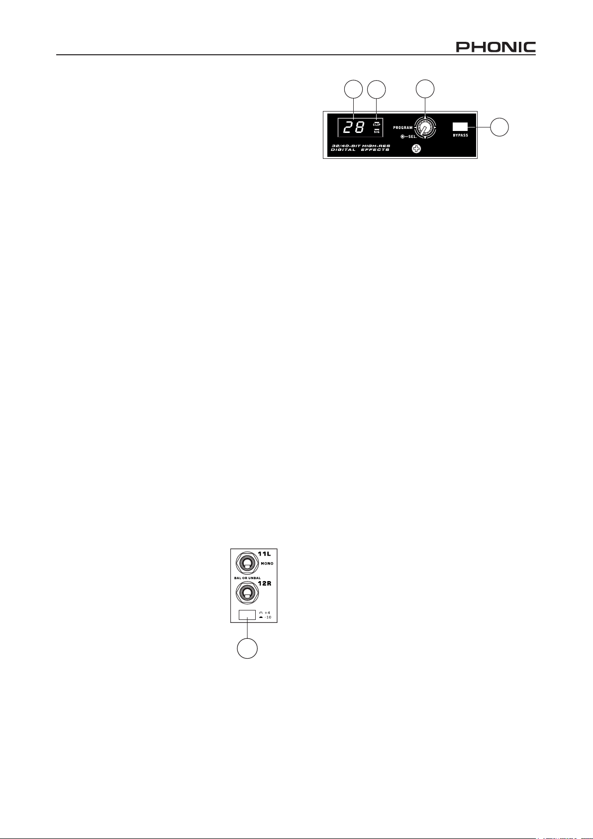
INTERFASE FIREWIRE...................30
ESPECIFICACIONES......................37
TAblA DE EFECTOS DIgITAlES....55
APlICACIONES...............................56
目录
简介...............................40
特色...............................40
包装内附件.....................40
准备工作........................40
声道设定........................40
连接操作........................41
控制和设定.....................42
FIREWIRE接口..............46
规格...............................53
数字效果表.....................55
应用...............................56
DIMENSION.............................58
blOCk DIAgRAM....................59
Phonic preserves the right to improve or alter any information within this document without prior notice
Phonic se reserva el derecho de mejorar o alterar cualquier información provista dentro de este documento sin previo aviso
DIMENSIóN.....................................58
DIAgRAMAS DE blOQUE..............59
PhONIC保留不预先通知即可更新本手册的权利
尺寸...............................58
线路图............................59
V1.0 11/19/2008
Page 3
IMPORTANT SAFETY INSTRUCTIONS
The apparatus shall not be exposed to dripping or splashing and that no objects filled with liquids, such as vases,
shall be placed on the apparatus. The MAINS plug is used as the disconnect device, the disconnect device shall
remain readily operable.
Warning: the user shall not place this apparatus in the confined area during the operation so that the mains switch
can be easily accessible.
1. Re a d these in struc t ions bef o re oper a ting th i s
apparatus.
2. Keep these instructions for future reference.
3. Heed all warnings to ensure safe operation.
4. Follow all instructions provided in this document.
5. Do not use this apparatus near water or in locations
where condensation may occur.
6. Clean only with dry cloth. Do not use aerosol or liquid
cleaners. Unplug this apparatus before cleaning.
7. Do not block any of the ventilation openings. Install
’
in accordance with the manufacturer
s instructions.
8. Do not install near any heat sources such as radiators,
heat registers, stoves, or other apparatus (including
amplifiers) that produce heat.
9. Do not defeat the safety purpose of the polarized or
grounding-type plug. A polarized plug has two blades
with one wider than the other. A grounding type plug
has two blades and a third grounding prong. The wide
blade or the third prong is provided for your safety. If
the provided plug does not fit into your outlet, consult
an electrician for replacement of the obsolete outlet.
CAUTION: TO REDUCE THE RISK OF ELECTRIC SHOCK,
DO NOT REMOVE COVER (OR BACK)
NO USER SERVICEABLE PARTS INSIDE
REFER SERVICING TO QUALIFIED PERSONNEL
The lightning flash with arrowhead symbol, within an
equilateral triangle, is intended to alert the user to the
presence of uninsulated
product
’
s enclosure that may be of sufficient
magnitude to constitute a risk of electric shock to persons.
The exclamation point within an equilateral triangle is in
tended to alert the user to the presence of important operat
ing and maintenance (servicing) instructions in the literature
accompanying the appliance.
“
dangerous voltage” within the
WARNING: To reduce the risk of fire or electric shock, do
not expose this apparatus to rain or moisture.
-
-
10. Protect the power cord from being walked on or
pinched particularly at plug, convenience receptacles,
and the point where they exit from the apparatus.
11. Only use attachments/accessories specified by the
manufacturer.
12. Use only with a car t, sta nd, tripod, bracket, or
table specified by the manufacturer, or sold with
the apparatus. When a cart is used, use caution
wh e n movin g the car t /appa r atus
combination to avoid injury from tipover.
13. Unplug this apparatus during lighting
st orms or when un u sed fo r long
periods of time.
14. Refer all servicing to qualified service personnel.
Servicing is required when the apparatus has been
damaged in any way, such as power-supply cord or
plug is damaged, liquid has been spilled or objects
have fallen into the apparatus, the apparatus has
been exposed to rain or moisture, does not operate
normally, or has been dropped.
CAUTION: Use of controls or adjustments or performance
of procedures other than those specified may result in
hazardous radiation exposure.
Page 4

Introduction
Thank you for choosing one of Phonic’s many quality
compact mixers. The helix board 18 FireWire MkII mixing
console - designed by the talented engineers that have
created a variety of mixers fantastic in style and performance
in the past - displays similar prociency that previous Phonic
products have shown; with the addition of such innovative
features as FireWire interface. The helix board 18 FireWire
MkII features full gain ranges, amazingly low distortion
levels, and incredibly wide dynamic ranges - just showing
the dominance these small machines will have in the mixing
World.
The FireWire interface of the helix board 18 FireWire MkII
allows users to stream up to 16 individual channels to any PC
or Mac, allowing for recording, editing, tweaking and deletion
of all tracks at will. Then, when all your mixing is done, your
nal product can be burnt onto CD. You can also receive
2 input channels (or returns) from the FireWire interface to
monitor your mix on your helix board.
Also included with the helix board 18 FireWire MkII mixer is
Steinberg Cubase lE 4 software, giving users a taste of the
operation of professional Digital Audio Workstation software
by allowing users to record up to 8 tracks simultaneously.
Other high performance Digital Audio Workstation software
will allow upto 16 channels to be simultaneously streamed
and recorded. All-in-all, the helix board 18 FireWire MkII will
no doubt prove itself to have been a valuable investment.
Features
• 18-input small-format analog mixer with extremely low
noise circuitry
• 96khz FireWire interface for streaming 16 independent
channels of audio to computer with near-zero latency
• 2 channels of monitoring from computer via FireWire
interface, can be assigned to control room monitors, main
mix and aux1
• Pre/post switch for swapping streaming input channels to
computer from pre low cut, EQ to post EQ, post fader
• Channel 15/16 routed to Computer can be selected from
main mix, group 1/2 and AUx 2/3
• DFX, our 40-bit high denition algorithm digital multi-
effect processor with 100 programs plus tap delay and
foot switch jacks
• Six Mic/line channels with inserts
• 8 extremely low noise mic preamps
• Four stereo line channels
• 3-band EQ with swept mid-range
• 75 Hz low-cut lter on mono channels
• Three AUx sends, one with Pre/Post switch
• Two stereo AUx returns with effect to monitor level
control
• +48V phantom power on Mic channels
• Solo feature on each input and output
• Two true subgroups with main l and R routing switches
• built-in switching power supply with universal connector,
100-240 VAC, 50/60 hz
• Rack-mounting kit included
• S/PDIF digital audio output
• Compatible with Mac OSx and Windows xP/Vista
• Steinberg Cubase lE 4 included
We know how eager you are to get started - wanting to get
the mixer out and hook it all up is probably your number one
priority right now - but before you do, we strongly urge you to
take a look through this manual. Inside, you will nd important
facts and gures on the set up, use and applications of your
brand new mixer. If you do happen to be one of the many
people who atly refuse to read user manuals, then we just
urge you to at least glance at the Instant Setup section. After
glancing at or reading through the manual (we applaud you
if you do read the entire manual), please store it in a place
that is easy for you to nd, because chances are there is
something you missed the rst time around.
Package Includes
1 x helix board 18 FireWire MkII mixer
1 x FireWire cable
1 x DVD with ASIO & WDM drivers and Steinberg Cubase
lE 4 software
1 x Power cable
1 x Rack mounting kit
If any items are missing from your package, please contact
your nearest Phonic dealer.
4 helix board 18 FireWire MkII
Page 5

Getting Started
Channel Setup
1. Ensure all power is turned off on your mixer. To totally
ensure, the AC cable should not be connected to the unit.
2. All faders and level controls should be set at the lowest
level and all channels switched off to ensure no sound is
inadvertently sent through the outputs when the device
is switched on. All levels can be altered to acceptable
degrees after the device is turned on.
3. Plug all necessary instruments and equipment into the
device’s various inputs as required. This may include line
signal devices, such as keyboards and drum machines,
as well as microphones and/or guitars, keyboards, etc.
4. Plug any necessary equipment into the device’s various
outputs. This could include ampliers and speakers,
monitors, signal processors, and/or recording devices.
5. Plug the supplied AC cable into the AC inlet on the back
of the device and a power outlet of a suitable voltage.
6. Turn the power switch on.
7. Consult the FireWire section of this manual for more
information on its setup and usage.
1. To ensure the correct audio level of the input channel is
selected, each of the Mixer’s Channel’s ON buttons should
be disengaged (which should turn the corresponding lED
indicator off), as well as the Solo buttons on each channel
and all buttons in the Control Room Source section, with
exception to the Main l/R button.
2. Ensure the channel you wish to set has a signal sent to it
similar to the signal that will be sent when in common use.
For example, if the channel has a microphone connected
to it, then you should speak or sing at the same level
the performer normally would during a performance; if a
guitar is plugged into the channel, then the guitar should
also be strummed as it normally would be (and so on).
This ensures levels are completely accurate and avoids
having to reset them later.
3. Move the Channel fader and Maser fader to around the 0
db mark.
4. Turn the Channel ON.
5. Pushing the channel’s Solo button and releasing the Pre/
Post button on the CTRl RM section will send the prefader signal of the activated channel to the Control Room
/ Phones mixing bus and the level Meter will display the
Control Room’s signal properties.
6. Set the gain so the level meter indicates the audio level is
around 0 db (it is advisable to never let the level exceed 7
db).
7. This channel is now ready to be used; you can stop
making the audio signal.
8. you can now repeat the same process for other channel if
you wish.
helix board 18 FireWire MkII
5
Page 6

Making Connections
7
Inputs and Outputs
1. XLR Microphone Jacks
These jacks accept typical 3-pin xlR inputs for balanced and
unbalanced signals. They can be used in conjunction with
microphones – such as professional condenser, dynamic or
ribbon microphones – with standard xlR male connectors,
and feature low noise preampliers, serving for crystal clear
sound replication. The helix board 18 FireWire MkII features
a total of eight Microphone inputs.
NB. When these inputs are used with condenser microphones, the
Phantom Power should be activated. however, when Phantom Power
is engaged,single ended (unbalanced) microphones and instruments
should not be used on the Mic inputs.
2. Line Inputs
This input accepts typical 1/4” TRS (balanced) or TS
(unbalanced) inputs, for balanced or unbalanced signals.
They can be used in conjunction with a wide range of line
level devices, such as keyboards, drum machines, electric
guitars, and a variety of other electric instruments.
1
5
6
4
5. AUX Sends
These 1/4” TRS outputs may be used to connect to an
external signal processor, or even to an amplier and
speakers (depending on your desired settings) from the
mixer. The signal from the AUx Sends is controlled by the
AUx master controls (on the face of the mixer), which obtain
their signal from the AUx controls located on each channel
strip. The helix board 18 FireWire MkII features a total of 3
AUx Sends. When using the FireWire interface, AUx Send
1 can be elected to receive the audio signal sent from the
Computer, for monitoring or recording purposes.
6. Phones
This stereo output port is suited for use with headphones,
allowing monitoring of the mix. The audio level of this output
is controlled using the Control Room / Phones control.
10
8
9
2
3. Stereo Channels
The helix board 18 FireWire MkII also
features a few stereo channels, thrown
in for maximum exibility. Each of these
stereo channels features two 1/4” phone
jacks, for the addition of various line level
input devices, such as electronic keyboards,
guitars and external signal processors or mixers, as well as
xlR Microphone jacks on channels 7/8 and 9/10, allowing
users to option of using the channel as a microphone input
channel. If you wish to use a monaural device on a stereo
input, simply plug the device’s 1/4” phone jack into the left
(mono) input and leave the right input bare. The signal will be
duplicated to the right due to the miracle of jack normalizing.
4. AUX Returns
These 1/4” TS inputs are for the return of audio to the helix
board 18 FireWire MkII mixer, processed by an external
signal processor. If really needed, they can also be used as
additional inputs. The feed from these inputs can be adjusted
using the AUx Return controls on the face of the mixer. When
connecting a monaural device to the AUx Return 1 and 2
inputs, simply plug a 1/4” phone jack into the left (mono)
input, and the signal will appear in the right as well.
3
7. Record Out
These outputs will accommodate RCA cables, able to be
fed to a variety of recording devices. Also included is a mini
stereo jack for the addition of recording devices such as MD
players, and even laptop computers.
8. 2T Return
These RCA inputs are used to connect the mixer with
parallel external devices, such as sub mixers or CD, Tape
and Cassette Players. Also included are mini stereo jacks,
for receiving signals from audio devices like portable CD, MD
and MP3 players.
9. Main Outputs
These two 1/4” TRS balanced jacks will output the nal stereo
line level signal sent from the main mixing bus. The primary
purpose of these jacks is to send the main output to external
devices, which may include power ampliers (and in-turn, a
pair of speakers), other mixers, as well as a wide range of
other possible signal processors (Equalizers, Crossovers,
etc.).
10. Group Outputs
These balanced 1/4” TRS phone jacks output the nal feed
from the group 1 and 2 mix controlled by the group level
faders. These outputs can be used to feed a wide range of
devices, such as mixers, signal processors, and even to
connect an amplier and speakers to be used along with the
Main Speakers, for a more rounded audio experience.
6 helix board 18 FireWire MkII
Page 7
Rear Panel
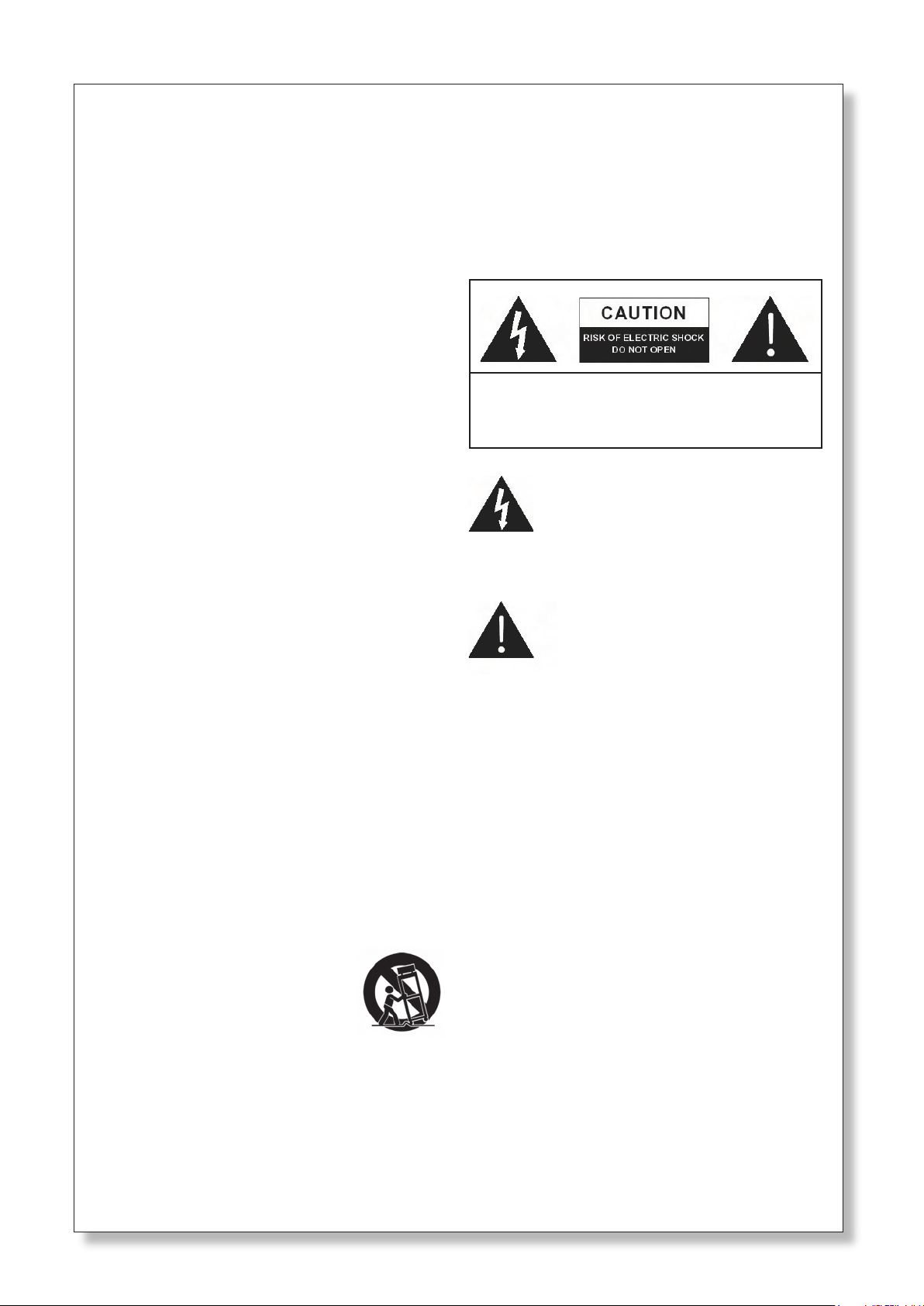
11. Channel Inserts
located on the rear of the helix board 18 FireWire MkII, the
primary use for these TRS phone jacks is for the addition of
external devices, such as dynamic processors or equalizers,
to mono input channels 1 through to 6. This will require a
y cord that can send (pre-fader and pre-EQ) and receive
signals to and from an external processor. The tip of the TRS
plug is for sending of the signal to the external device, the
ring is for return of the signal to the helix board 18 FireWire
MkII, and the Sleeve is the grounding.
15. S/PDIF Output
This RCA S/PDIF (Sony / Phillips Digital Interface) jack is
for the output of digital audio signals, allowing the Main l&R
audio from the mixer to be passed to another device without
having to convert the signal from digital to analog and back
again. The output sampling rate is permanently set to 44.1
khz per second when no FireWire connection is made. If the
FireWire output is connected to a computer, than the S/PDIF
output sampling rate will be the same as that set by the helix
board Control Panel software.
16. FireWire Connections
The two FireWire connectors are for linking the helix board
18 FireWire MkII to a PC or Macintosh computer. It will allow
16 channels to be streamed to the computer (the amount
of channels you are able to record simultaneously depends
on the DAW software used), and 2 audio channels of the
computer to be returned to the mixer. Please observe the
FireWire section of this manual for more information.
11
12. Control Room Outputs
These two 1/4” phone jack outputs feed the signal altered
by the Control Room / Phones level control on the face of
the mixer. This output has extensive use, as it can be used
to feed the signal from the mixer to an active monitor, for
the monitoring of the audio signal from within a booth, or,
alternatively, for the addition of external signal processing
devices or mixers, as well as acting as a “side ll” output,
supplying audio to indoor areas that the main speakers do
not reach. When using the FireWire interface, this output
can be elected to be fed the audio signal from the Computer,
for monitoring of recording audio.
13. Foot Switch Jacks
These ports are for the inclusion of an unlatched foot switch,
used to remotely adjust properties of the built-in Digital Effect
processor. The jack on the right is used to turn the Digital
Effects on and off, whereas the jack on the left is used for
adjusting tap delay properties.
17. Power Connector
This port is for the addition of a power cable, allowing power
to be supplied to the mixer. Please use the power cable
that is included with this mixer only. The helix board 18
FireWire MkII features a switching power supply, suitable for
all zones.
Controls and Settings
Rear Panel
18. Phantom Power Switch
When this switch is in the on position, it activates +48V of
phantom power for all microphone inputs, allowing condenser
microphones (well, the ones that don’t use batteries) to be
used on these channels. Activating Phantom Power will be
accompanied by an illuminated lED above the left channel
level Meter. before turning Phantom Power on, turn all level
controls to a minimum to avoid the possibility of a ghastly
popping sound from the speakers.
NB. Phantom Power should be used in conjunction with balanced
microphones. When Phantom Power is engaged, single ended
(unbalanced) microphones and instruments should not be used
on the Mic inputs. Phantom Power will not cause damage to most
dynamic microphones, however if unsure, the microphone’s user
manual should be consulted.
13
14. Main XLR Outputs
These two XLR ports will output the nal stereo line level
signal sent from the main mixing bus. The primary purpose
of these jacks is to send the main output to external devices,
which may include power ampliers (and in-turn, a pair
of speakers), other mixers, as well as a wide range of
other possible signal processors (equalizers, crossovers,
etcetera).
12
14
helix board 18 FireWire MkII
19. Power Switch
This switch is used to turn the mixer on and off. Ensure you
turn all level controls down before activating.
18
1917
1516
7
Page 8
20
21
22
23
24
26
27
25
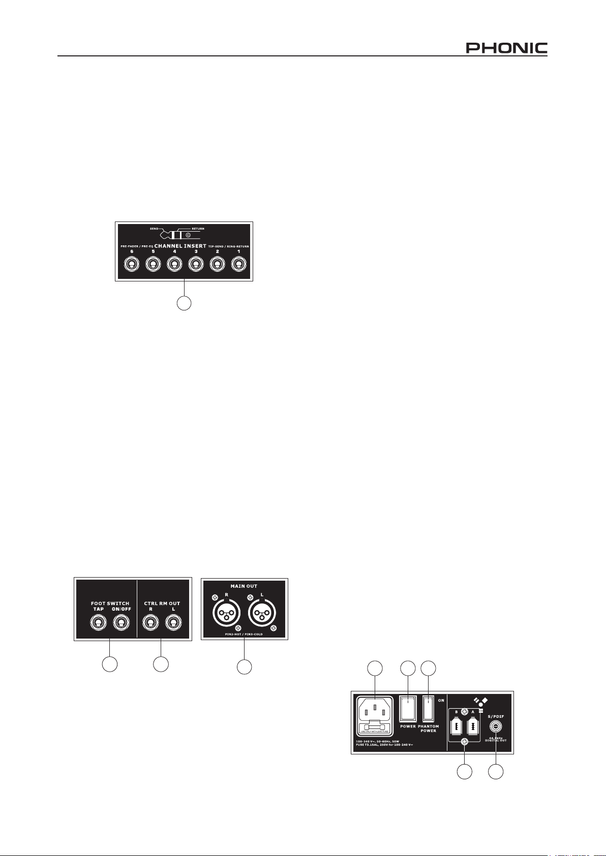
23. Middle Frequency Control
This control is used to provide a peaking style of boost and
cut to the level of middle frequency sounds at a range of .±15
db. These mixers also provide a sweep control, allowing
you to select a center frequency between 100 hz and 8
khz. Changing middle frequencies of an audio feed can be
rather difcult when used in a professional audio mix, as it is
usually more desirable to cut middle frequency sounds rather
than boost them, soothing overly harsh vocal and instrument
sounds in the audio.
Stereo channels 11/12 and 13/14 of the helix board 18
FireWire MkII feature a high-Mid and low-Mid control
instead of the typical controls described above. They provide
a peaking style of boost and cut to middle frequencies, where
the frequencies are set at 3 khz and 800 hz (high-Mid is set
at 3 khz and low-Mid is set at 800 hz). Stereo channels 9/10
and 11/12 have a single Middle Frequency control, with the
center frequency set at 2.5 khz.
28
29
30
31
33
Channel Controls
20. Low Cult Filter (75 Hz)
This button will activate a high-pass lter that reduces all
frequencies below 75 hz at 18 db per Octave, helping to
remove any unwanted ground noise or stage rumble. On
stereo channels 7/8 and 9/10, the low cut lter affects only
the xlR Microphone inputs (and not the line inputs).
21. Line/Mic Gain Control
This controls the sensitivity of the input signal of the line/
Microphone input. The gain should be adjusted to a level that
allows the maximum use of the audio, while still maintaining
the quality of the feed. This can be accomplished by adjusting
it to a level that will allow the peak indicator occasionally
illuminate.
32
24. Low Frequency Control
This control is used to give a shelving boost or cut of +/-15db
to low frequency (80hz) sounds. This will adjust the amount
of bass included in the audio of the channel, and bring more
warmth and punch to drums and bass guitars.
25. FireWire Pre/Post Switch
This switch is used to change the signal of the corresponding
channel that is sent to the Computer via the FireWire interface
between that of a pre-EQ, pre-fader, pre-low cut and that of a
post-EQ, post-fader, post-low cut. In the upper-most position,
the channel will be pre, and in the lower position post.
26. AUX Controls
These controls alter the signal level that is being sent to
the auxiliary 1 and 2 mixes. The signals of these mixes are
suitable for connecting stage monitors, allowing artists to
listen to the music that is being played. Also included is a
Pre/Post button, which alternates the feed to the AUx 2 mix
between a post and pre-fader feed.
27. EFX Control
This control alters the signal level that is sent to the EFx send
(AUx 3) output and the built-in digital effect processor. The
EFx send signal can be used in conjunction with external
signal processors (this signal of which can be returned to
mixer via the AUx return input), or simply as an additional
auxiliary output.
22. High Frequency Control
This control is used to give a shelving boost or cut of ±15
db to high frequency (12 khz) sounds. This will adjust the
amount of treble included in the audio of the channel, adding
strength and crispness to sounds such as guitars, cymbals,
and synthesizers.
28. Pan / Balance Controls
This alternates the degree or level of audio that the left and
right side of the main mix should receive. On mono channels,
the PAN control will adjust the level that the left and right
should receive (pan), where as on a stereo channel, adjusting
the bAl control will attenuate the left or right audio signals
accordingly (balance).
8 helix board 18 FireWire MkII
Page 9
29. On Button and Indicator
This turns the channel on, allowing the user to use the feed
from the channel’s inputs to supply the MAIN l/R, gROUP
1/2, AUx and EFx buses. The corresponding indicator will be
illuminated when turned on.
30. 1-2 and L-R Buttons
These handy buttons allow you to decide the audio path of
the corresponding channel. Pushing the “1/2” button allows
the signal to be sent to the group 1/2 mix, where the “l-R”
allows it to be sent to the Main l/R mix.
31. Peak Indicator
This lED indicator will illuminate when the channel hits high
peaks, 6 db before overload occurs. It is best to adjust the
channel level control so as to allow the PEAk indicator to
light up on regular intervals only. This will ensure a greater
dynamic range of audio. This indicator also doubles as a
Solo indicator, when the Solo button is engaged.
32. Solo Button
The Solo button is pushed to allow the signal of a corresponding
channel to be sent to the Control Room / Phones control (pre
or post fader, depending on the properties selected by the
pre / post button, located by the Control Room / Phones
control), for use with either headphones or studio monitors.
This also allows easier setting of the input gain and tracking
of audio by sound engineers. The Peak indicator above the
Solo button also doubles as the Solo Indicator, illuminating
when the Solo button is pushed in.
33. Channel Level Control (Fader)
This control will alter the signal level that is sent from the
corresponding channel to the appropriate mixing buses
(whether they are the MAIN l/R or AUx).
34. +4 / -10 Buttons
These buttons, located on each stereo input
channel, are used adjust the input sensitivity
of the corresponding channel, which will
adapt the mixer to external devices which
may use different operating levels. If the
input source is -10 dbV (consumer audio
standard), it is best to engage the switch,
allowing the signal to be heard. If the
input source is +4 dbu (professional audio
standard) the corresponding input channel’s button should
be disengaged to ensure the integrity of the Mixer’s circuitry.
If you are unsure of the source’s operating level, we suggest
leaving the switch disengaged until you test the source’s
signal. you can then engage if necessary (if the level of input
is obviously too low).
34
35
36
37
38
Digital Effect Section
35. Digital Effect Display
This 2-digital numeric display shows the program number
that is currently applied to your EFx audio signal. When you
rotate the Program control, you can scroll through different
program numbers; however the display will revert back to
the original program if a new program is not selected within
a few seconds. For a list of available effects, please observe
the Digital Effect Table.
36. Sig and Clip Indicators
located within the Digital Effect Display are Clip and Sig
lEDs. The Sig lED will light up when any signal is received
by the effect processor, and the Clip lED will light up shortly
before excessive signals are dynamically clipped. If the Clip
lED lights up too often, it may be advisable to turn down the
AUx 3/EFx master control to ensure the signal level is not
excessive.
37. Program Control
This control is used to scroll through the various effects.
Turning the control clockwise will allow users to ascend into
higher program numbers, and turning it counter-clockwise
will allow users to descend into lower program numbers.
When turning to a new program, a small LED will ash until
you push the program knob down – this will apply the effect.
When a tap-delay effect is selected, pressing this control will
allow users to select the tap-delay time.
by pushing the button several times, the effect processor
interprets the time between last two pushes and remembers
this as the delay time – until the button is pushed again. This
is kept even after the power is turned off. When the tap delay
effect is selected, a small lED (located between the two digit
display) will ash within the digital effect display window at
the selected intervals.
38. Effect Bypass
Use it to bypass the effects and monitor your audio before
and after the effect is applied. When the effect engine is
bypassed, the 2 small indicators on the digital effect display
will ash.
helix board 18 FireWire MkII
9
Page 10
40
41
39
44
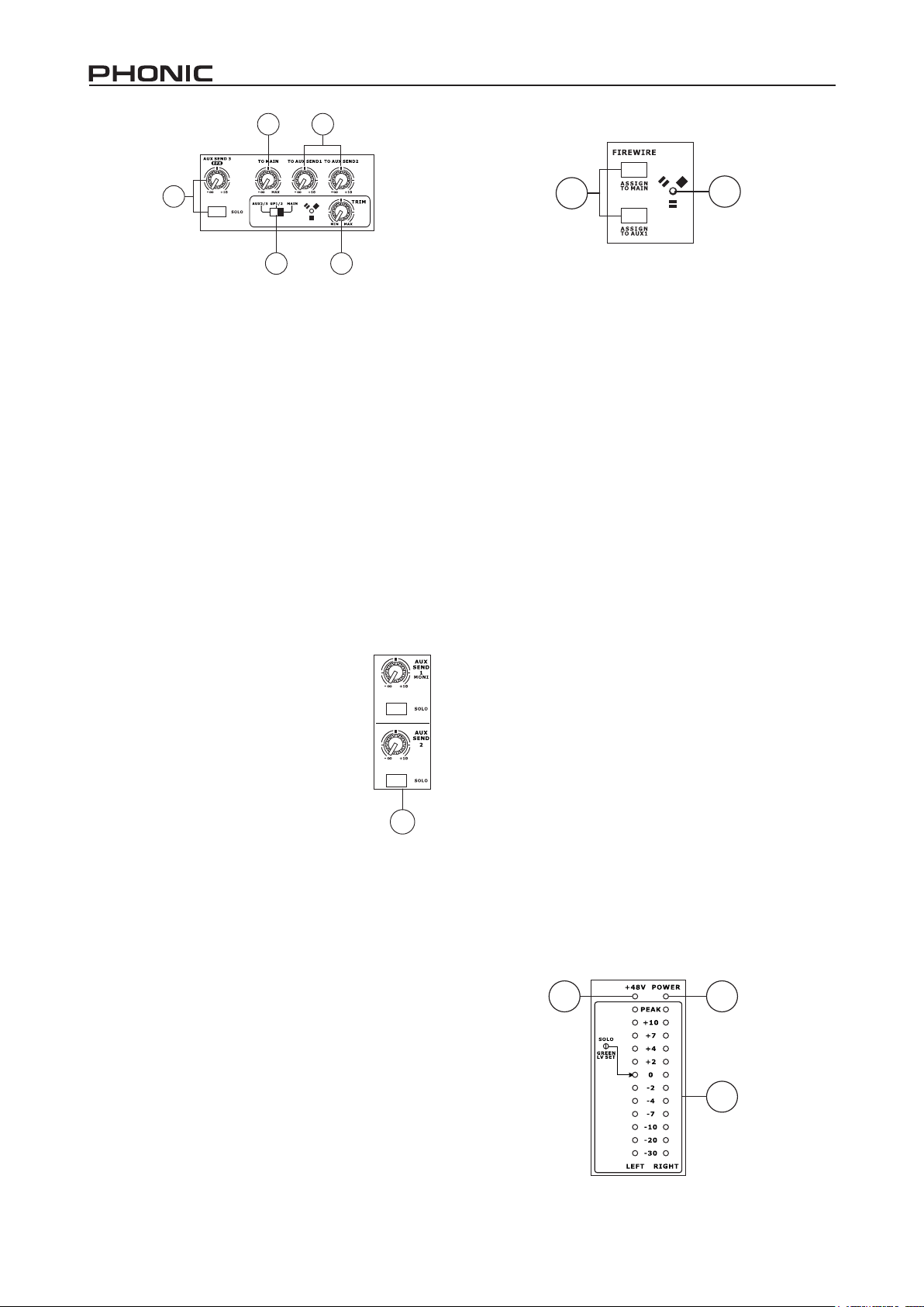
39. AUX 3 / EFX Send Control and Solo Button
This rotary control will adjust the level of the output signal
at the AUx 3 send jack, as well as determine the amount
of audio the built-in effects processor will receive. When
this control is set to it’s minimum position, neither the AUx
3 send nor the effect processor will receive a signal. The
accompanying Solo button allows the EFx Send signal to be
sent to the Control Room / Phones mix.
40. To Main Control
The “to Main” control will allow users to adjust the processed
signal that is sent to the Main.
41. To AUX 1/2 Controls
These controls allow users to send the signal processed
by the effects processor to the AUx 1 or 2 mix, allowing for
monitoring of the signal. This is called “Effect to Monitor.”
43
Master Section
42. AUX Send Controls and Solo Buttons
These two controls are for adjusting the audio
level that is sent to the corresponding AUx
outputs, the signal of which is initially taken from
each channel’s individual AUx send controls.
Pushing one of the accompanying Solo buttons
will send the corresponding AUx signal to the
Control Room / Phones mix (pre or post fader,
depending on the Pre / Post button).
43. FireWire Trim Control
This is one of the newest features of the helix board 18
FireWire MkII. The FireWire trim control can be used to
adjust the level of the outgoing FireWire signal (which will
be received by the computer) from the AUx 2/3, group 1/2
or Main l/R (depending on the FireWire Select switch). If
the input signals received by your computer are noticeably
excessive, using this control could help to attenuate the
signal to an acceptable degree.
42
45
45. FireWire “Assign to” Buttons
The Assign to Main and Assign to AUx 1 buttons allow users
to determine the destination of the stereo FireWire return
signal.
46. FireWire Indicator
This blue lED indicator will illuminate when a connection is
established through the FireWire interface.
47. +48V Indicator
This indicator will illuminate when Phantom Power is
activated.
48. Power Indicator
The Power Indicator will light up when the power of the mixer
is on.
49. Level Meter
This dual 12 segment level meter gives an accurate
indication of when audio levels of the Main l/R output reach
certain levels. The 0 db indicator illuminates is approximately
equal to an output level of +4 dbu (balanced), and the PEAk
indicator illuminates just before the signal is dynamically
clipped. It is suggested that users set the various levels
controls so that the level sits steadily around 0 db to make
full use of audio, while still maintaining fantastic clarity.
When the Solo indicator, located beside the level Meter, is
illuminated, one or more Solo buttons has been pushed. In
that case, the level meter will display properties of the Solo
signal, which is helpful with setting of channel properties. If
Solo indicator illuminates green, this means the Solo feed is
a pre-fader signal. If the Solo indicator illuminates red, the
feed is post-fader. If the no Solo buttons are activated, the
Control Room source signal properties are displayed by the
level Meter.
47
46
48
44. FireWire Select Switch
This switch determines which of the helix board’s signals will
be used for the FireWire channels 15 and 16 sent through
the FireWire interface to the computer. Users can choose to
send the two channel signal from the Auxiliary 2/3, group 1/2
or Main mixes (all pre-level controls) to the computer.
49
10 helix board 18 FireWire MkII
Page 11
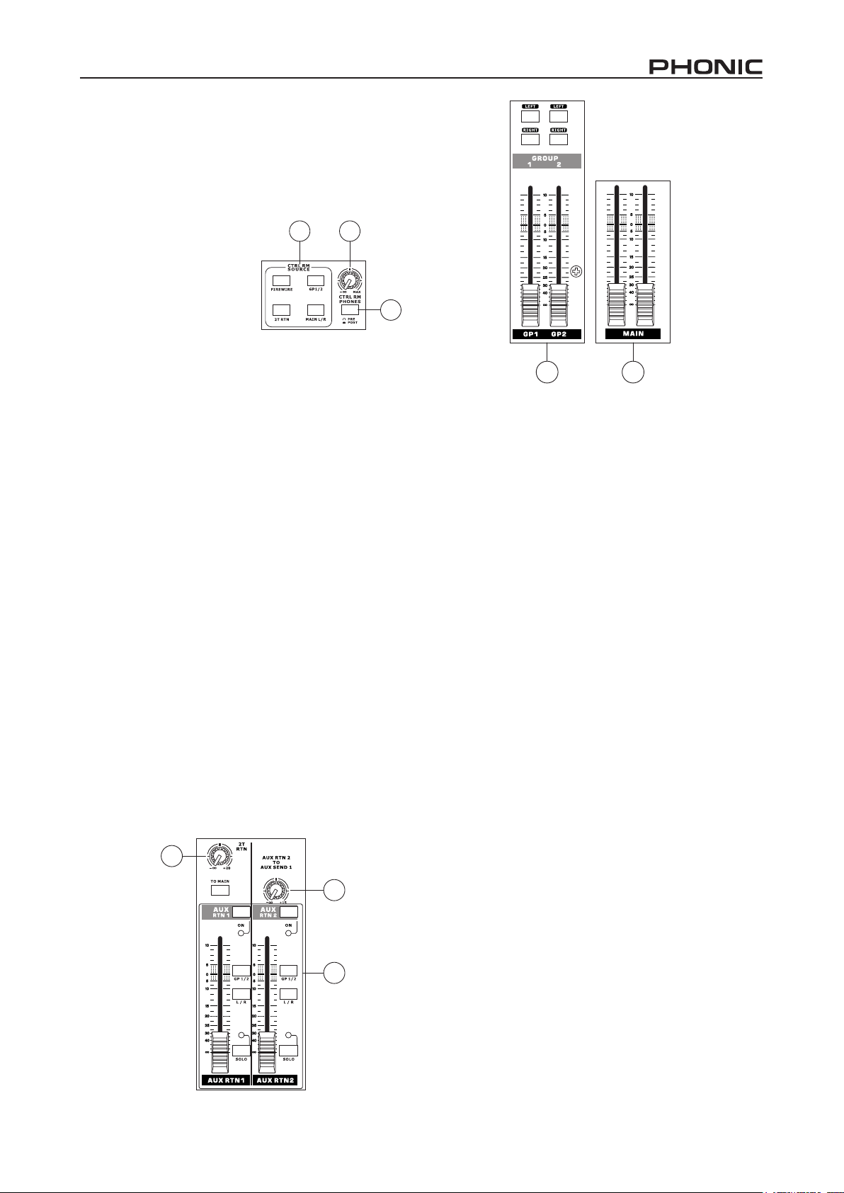
50. Control Room Source Buttons
This set of buttons allows users to select which signals they
wish to send to the Control Room / Phones output. There is
a button each for the FireWire, group 1-2, 2T Return and
Main mixes. These signals can be monitored simultaneously
if required.
51. Control Rooms / Phones
Level Control
This rotary control will allow
users to adjust the audio level
of the Control Room / Phones
signal (received by solo signal,
or as chosen in the Source
Select buttons).
52. Control Room Pre / Post Button
The Pre / Post button alters the Solo signals received by
the Control Room / Phones mix between Post and Pre fader
signals. When set to Post, the Solo Indicator will light up
red; when set to Pre, the Solo Indicator will light up green
(channel level set).
53. 2T Return Control and To Main Button
Use this rotary control to adjust the signal level received
through the RCA 2T Return inputs. The To Main button allows
users to send the 2T Return signal to the main mix.
54. AUX Return 1 and 2 Faders
This 60mm fader adjusts the signal level of audio fed through
the stereo AUx Return input. This AUx Return features l/
R, gP 1/2 assign buttons, enabling users to send the audio
feed to the corresponding mixing buses. Also, features
a Solo button that sends the signal directly to the Control
Room / Phones mix. The On button allows you to turn the
AUx Return channel on and off. Activation of the AUx Return
or AUx Return Solo will be accompanied by an illuminated
lED.
55. AUX Return 2 to AUX 1 Control
This rotary control allows users to adjust the level of audio
that is sent from the AUx Return 2 signal to the AUx Send
1 mix.
50
51
52
56 57
56. Group 1/2 Controls
These two faders are the nal level control for the Group
1 and 2 audio feeds, sent to the group 1 and 2 outputs.
These faders can be fed a signal from the various mono
and stereo channels, as well as EFx Returns, depending on
your selections. When pushed all the way up, these faders
provide 10 db of gain to the signal, and, when set all the way
down, effectively mute the signal.
The group Controls also feature left and Right buttons,
which allow you to send the group 1/2 signal to the Main left
and Right mix.
57. Main L/R Faders
These two faders are the nal level control for the Main Left
and Right audio feeds, sent to the Main l and R outputs.
These faders are possibly fed by the various mono and
stereo channels, as well as AUx and EFx returns and 2T
inputs, depending on the your selections. When pushed all
the way up, these faders provide 10 db of gain to the signal,
and, when set all the way down, effectively mute the signal.
53
helix board 18 FireWire MkII
55
54
11
Page 12
FireWire Interface
System Requirements
The following are the minimum required specications for use with the Helix Board 18 FireWire MKII mixer. If your computer does
not meet these requirements, you will experience lagging of audio and possible freezing of your computer when attempting to
operate the mixer.
Windows
• Microsoft® Windows® xP SP1 and SP2
• Available FireWire port (suggested FireWire Interface: ADS Pyro 64 FireWire card with TI chip)
• Intel Pentium® 4 processor or equivalent AMD Athlon processor
• Motherboard with Intel or VIA chipset
• 5400 RPM or faster hard disk drive (7200 RPM or faster with 8 Mb cache recommended)
• 256 Mb or more of RAM (512 Mb recommended)
Macintosh
• OS x 10.3.5 or later with native FireWire support
• g4 or newer processor
• 256 Mb or more of RAM
Driver Installation
To use the Helix Board FireWire mixer efciently (or at all) on a PC, it is important to install all the necessary drivers from the included CD (ASIO and WDM drivers). It is important that users read all instructions carefully before continuing on to the each step
of installation, as users will be required to unplug and plug in their FireWire device. This is not necessary for Mac users.
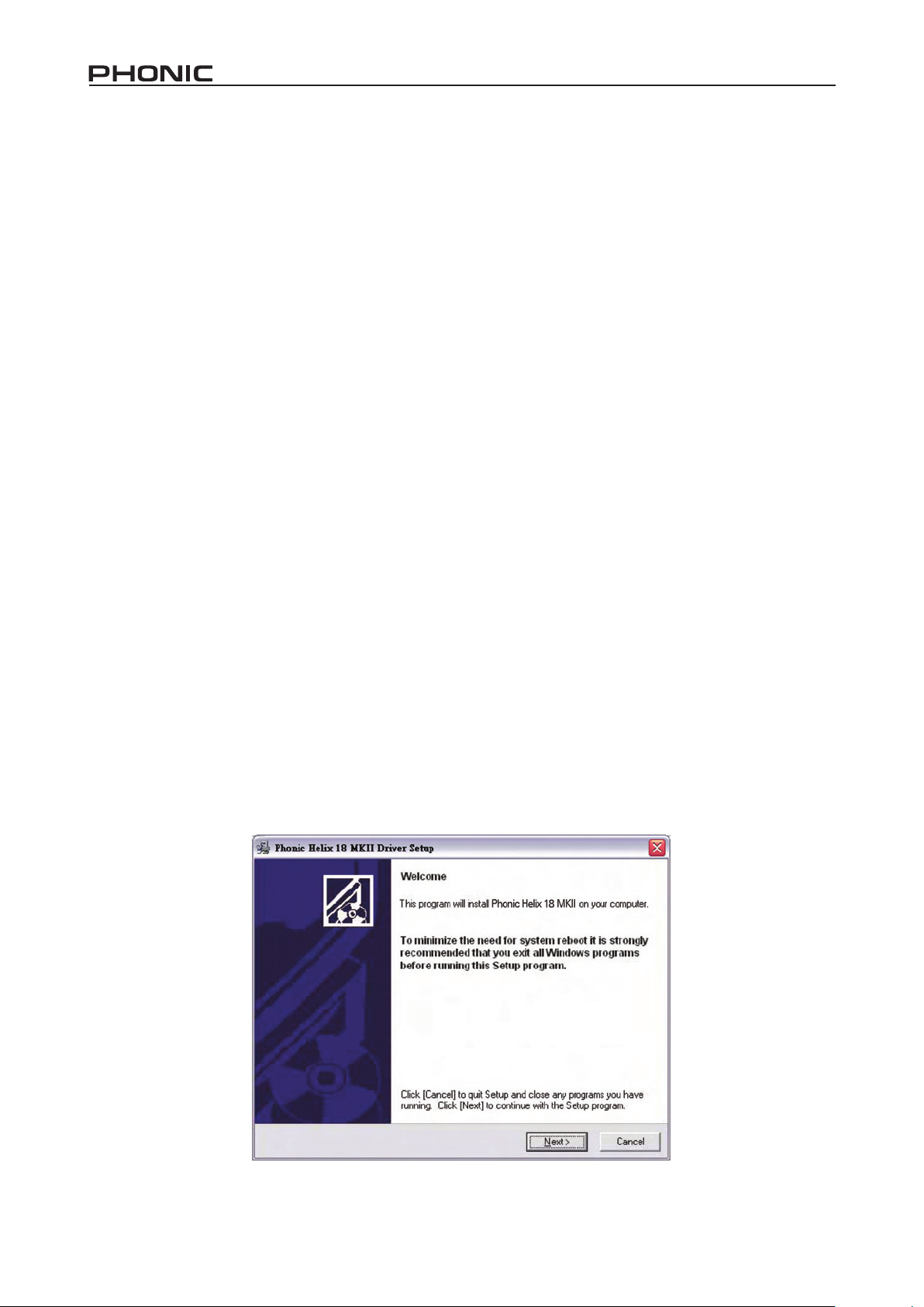
Windows XP (with Service Pack 1 or 2)
1. It is recommended that you quit all applications before starting the installation process.
2. Ensure the helix board FireWire is not yet connected to your Computer’s FireWire input.
3. Insert the installation CD included with your helix board FireWire mixer into the CD-ROM drive of your computer. If the CD does
not automatically start the installation process within a few moments, then navigate to “My Computer” g your CD-ROM drive
g “Drivers and Control Panel” g double-click “setup.exe” to begin the installation manually. The helix board FireWire Control
Panel software also will be installed at this time.
4. Follow the installation instructions.
Make sure no other programs are running on your PC and that the
helix board 18 FireWire MkII is not connected to your PC, then click “Next”.
12 helix board 18 FireWire MkII
Page 13
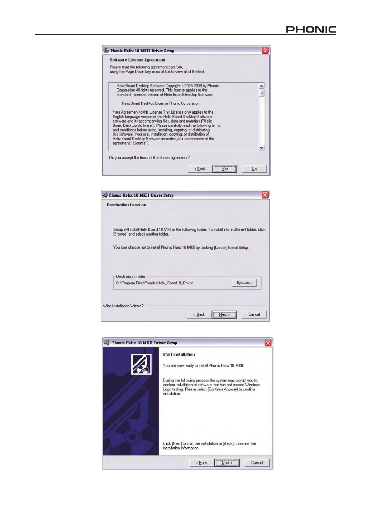
Read and accept the terms of the license Agreement and click “yes” to continue.
Either select a new destination for the installation, or else click “Next” to accept the default directory.
helix board 18 FireWire MkII
Click “Next” to begin the installation.
13
Page 14
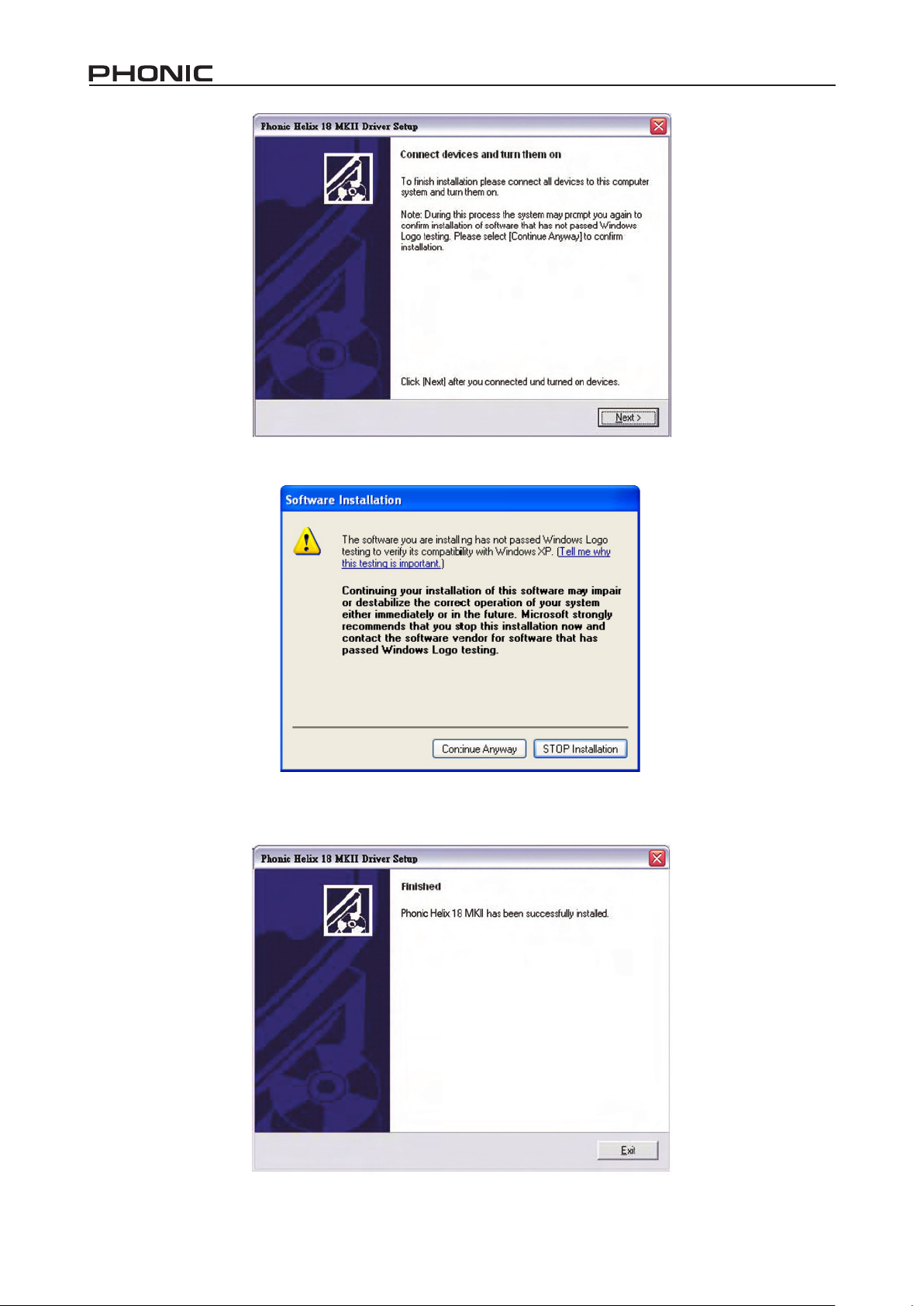
Connect the helix board 18 FireWire MkII to the Computer and turn the power on.
If a message is displayed indicating that the software has not passed Windows logo test,
click “Continue Anyway”.
After installation is complete, users are free to use the device as they wish.
14 helix board 18 FireWire MkII
Page 15
Macintosh OS X (10.3.5 or later)
The helix board 18 FireWire MkII works with the primary audio drivers of Macintosh OS x 10.3.5 and later. First verify that you
are running Macintosh OS x 10.3.5 or above, then connect the helix board 18 FireWire MkII to a FireWire port to the computer.
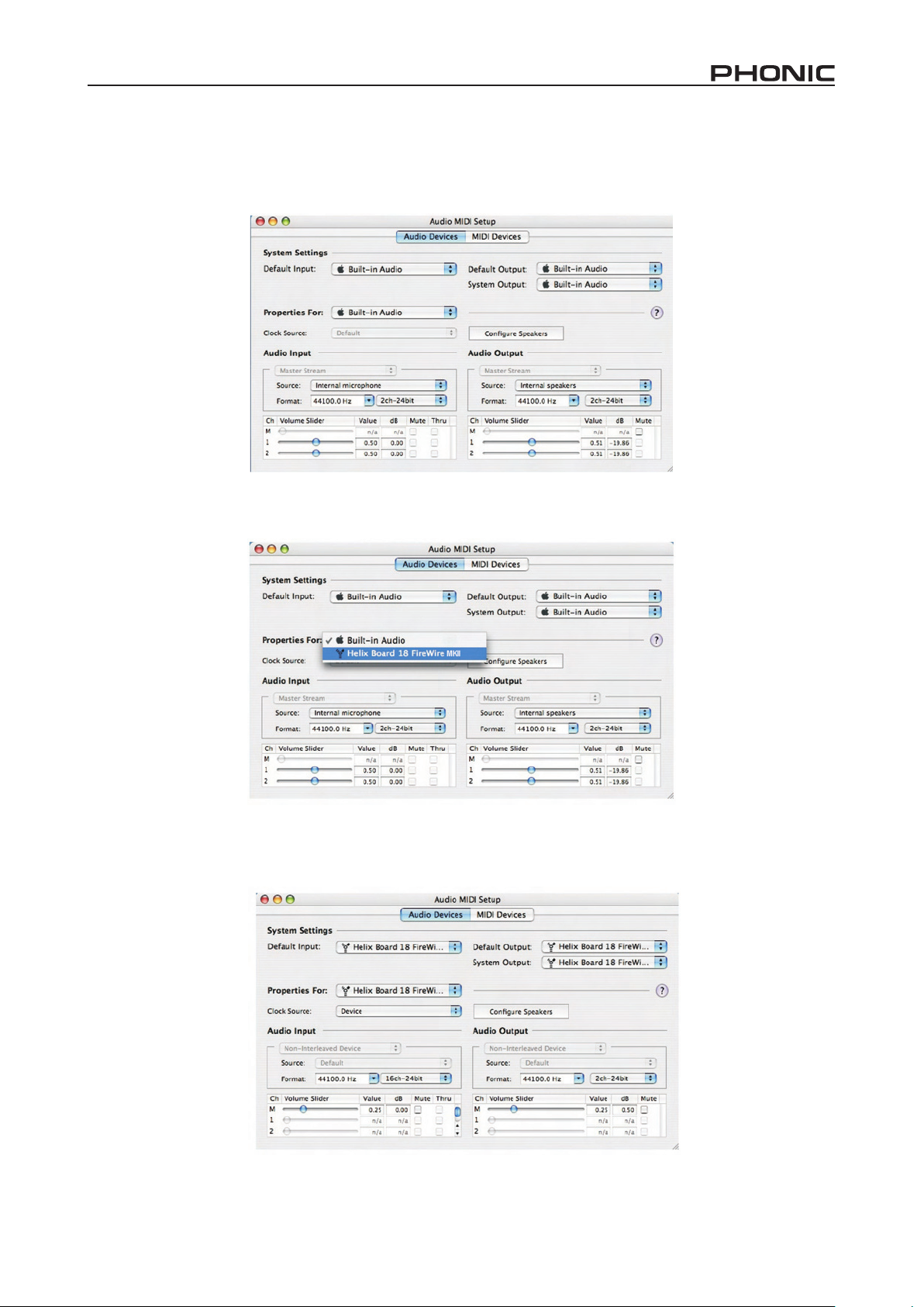
To ensure your helix board 18 FireWire MkII is working, enter the Utilities folder and double-click the Audio MIDI Setup icon.
Enter the Audio Device’s section. From the “Properties for” pull-down tab,
select helix board 18 FireWire MkII.
At the bottom of the window, users can edit the setup of the helix board 18 FireWire MkII.
Users may also opt to make the helix board 18 FireWire MkII their default input and/or output device.
Mac users are able to use garageband Digital Audio Workstation Software,
helix board 18 FireWire MkII
Properties such as sampling rate and clock source can be altered.
in conjunction with the helix board 18 FireWire MkII.
15
Page 16
Channel Assignment
When using a Digital Audio Workstation on a PC, and within
the included Phonic helix board 18 FireWire MkII control
panel software, the following names have been attributed
to the input channels of the FireWire mixer. They can be
altered through the control panel software included with the
mixer.
Cubase LE 4
Cubase lE 4 is a fairly powerful program provided along with
the helix board 18 FireWire MkII mixer that allows users to
record, edit, delete, and alter their tracks. Please note that
only 4 tracks can be recorded at once with the version of Cu-
base included, and users must upgrade or nd other suitable
DAW software if they choose to record more tracks.
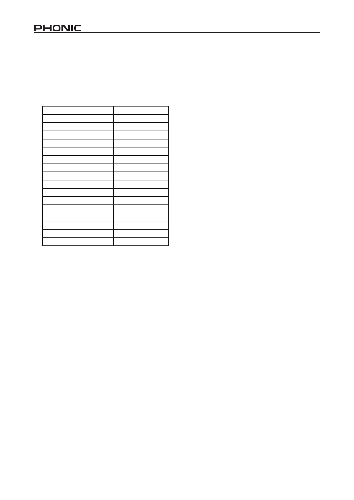
FireWire Input Channel Name Mixer Channel
Phonic hb 18 MkII Ch 1 Channel 1
Phonic hb 18 MkII Ch 2 Channel 2
Phonic hb 18 MkII Ch 3 Channel 3
Phonic hb 18 MkII Ch 4 Channel 4
Phonic hb 18 MkII Ch 5 Channel 5
Phonic hb 18 MkII Ch 6 Channel 6
Phonic hb 18 MkII Ch 7 Channel 7 (Stereo l)
Phonic hb 18 MkII Ch 8 Channel 8 (Stereo R)
Phonic hb 18 MkII Ch 9 Channel 9 (Stereo l)
Phonic hb 18 MkII Ch 10 Channel 10 (Stereo R)
Phonic hb 18 MkII Ch 11 Channel 11 (Stereo l)
Phonic hb 18 MkII Ch 12 Channel 12 (Stereo R)
Phonic hb 18 MkII Ch 13 Channel 13 (Stereo l)
Phonic hb 18 MkII Ch 14 Channel 14 (Stereo R)
Phonic hb 18 MkII Main l user denable
Phonic hb 18 MkII Main R user denable
To alter an input channel’s name on your computer, open the
helix board 18 FireWire MkII control panel software. On the
left hand side of the control panel, users will nd the settings
categories. by clicking “Input Channels”, the main window
will display the titles input channels. you can then highlight
the channel names and press the “Edit Channel Name” button on the bottom of the control window. A new window will
appear that will allow users to adjust the channel name.
If you would like to use the helix board 18 FireWire MkII as
your default audio output device on you PC, simply go into
the Windows control panel, and select “Sound and Audio Devices”. Select the Audio tab, and use the pull-down menu to
select the helix board 18 FireWire MkII from the list of available output devices. The helix board 18 FireWire MkII can
also be selected as the default output device for individual
programs by editing said programs’ settings / options.
Installation
Insert the Cubase lE 4 installation CD that came with your
mixer into the CD drive of your computer. Run the installer.
The serial number will be automatically entered in when installing.
Setup
After successfully completing the installation process, the fol-
lowing process must be followed to work efciently with the
helix board 18 FireWire MkII mixer.
1. Open the Cubase lE 4 program.
2. go to the ‘Devices’ pull-down menu and select ‘Device
Setup’. On the left, select ‘VST Multitrack’.
3. From the ASIO Driver drop-down list select the “Phonic
ASIO Driver”. A pop-up box will ask you if you want to
switch the ASIO driver. Click ‘Switch’. This completes the
basic installation and setup.
4. Activating audio tracks received from the helix board
mixer.
a. go to the “devices” pull-down menu and select ‘VST
Inputs’. This will display the various inputs (“Phonic
hb 18 MkII Ch 1”, “Phonic hb 18 MkII Ch 2”, etc.)
b. Activate 8 of these channels by clicking the “Active”
button located next to each channel name. Please
note, only 8 input channels can be activated at any
one time. This is a limitation of Cubase lE 4, and if
more input channels are needed, we suggest upgrading to a higher version of Cubase, or use other DAW
software.
5. For further instructions on the operation of Cubase,
please consult the user manual by pressing F1 while the
program is open.
If you wish to reset the helix board 18 FireWire MkII ASIO
driver, simply go to the ‘devices’ pull-down menu and select
‘device setup’. Simply click “reset” and select the “Phonic
ASIO Driver”. Click ‘ok’ to continue and the helix board 18
FireWire MkII should once again become functional.
16 helix board 18 FireWire MkII
Page 17
Helix Board Control Panel
The helix board FireWire control panel can be accessed at
any time by entering choosing the shortcut from your Programs menu. This program will not only allow users to alter
their device and channel names and properties, but will also
let them correct for latency issues, change sampling rates,
and so forth. When opening the software, a number of options will be available for users to select from, allowing them
to adjust the available properties.
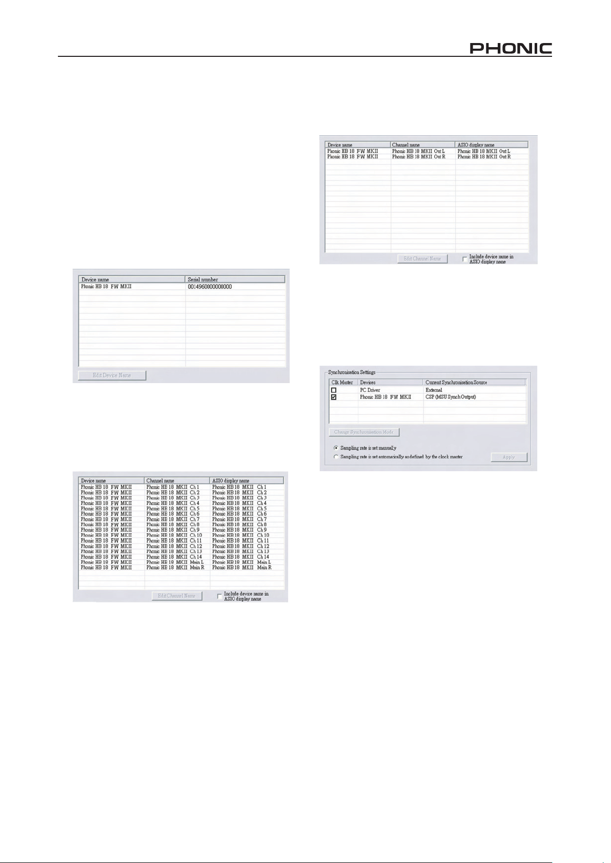
Devices
In the Devices section, users are able to view and edit the
name of the Phonic FireWire Devices connected to their
computer.
Output Channels
by entering the Output Channels section, users can view and
edit the names of the two output channels from the computer
to the helix board 18 FireWire MkII mixer.
Synchronization
In the Synchronization section, users can adjust the sampling rate and other synchronization properties. Many of
these adjustable properties, as they are, are set for optimum
performance and, unless you are sure of what you need to
change, are probably best left alone.
Input Channels
The Input Channels section allows users to view and edit
the name of the various input channels received from the
FireWire input. For a list of default channel names, please
consult the table on page 16.
First off, the synch mode can be altered, though making
this alteration is not recommended for novice users. The
synch mode is basically the way the computer determines
what the ‘clock source’ (ie. device that your computer will
use to determine the timing of all digital signals received) will
be. The default setting for this feature is “CSP”, meaning the
helix board 18 FireWire MkII is the “master” clock source
of the device. The other options allow users to make the
helix board 18 FireWire MkII follow the “timing” of whichever
device is the clock source. having two clock sources has
the potential to create very undesireable audio, so it is best
avoided. If the helix board 18 FireWire MkII is the only piece
of digital audio equipment attached to the computer, there is
no reason this option should be changed.
Users are also able to change between automatic and
manual sampling rate settings. When the sampling rate is
manually set, users can select between sampling rates of
44.1, 48.0, 88.2 and 96.0 khz per second. Many devices
have sampling rates that do not surpass 44.1 khz per second, therefore, when using multiple digital devices, users are
advised not to exceed this level unless they are sure the secondary device’s sampling rate can .
helix board 18 FireWire MkII
17
Page 18
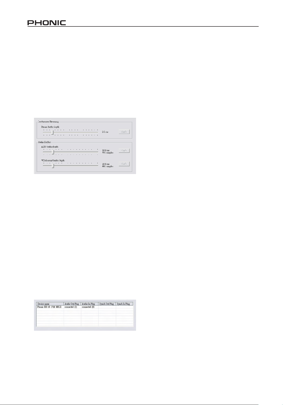
Settings
Users are able to adjust various buffer times in the Settings
section.
The Stream buffer Depth is adjustable between 0.5 and 20
milliseconds. It adjusts the buffer used when streaming a
signal from the helix board 18 FireWire MkII. If the depth is
set too high, an obvious latency will become evident. If the
depth is too low, various clicks and pops may become obvious. It is best to set the Stream buffer Depth to a level that
allows users to get the lowest latency, while still maintaining
an optimal performance. The default settings are ideal for
most computers.
The ASIO buffer Depth is adjustable between 4 and 40 milliseconds. This allows users to adjust the latency of the
stream received by ASIO driver-based software (including
Steinberg Cubase lE 4).
The WDM (Windows Driver Model) Sound buffer Depth is
adjustable between 4 and 40 milliseconds. This allows users
to adjust the latency of the stream received by WDM based
programs.
Also in this section, users are able to view their “drop out statistics”, where the number of times the FireWire connection
has been interrupted can be viewed.
Streams
In the Streams section, the helix board 18 FireWire MkII device properties can be viewed. Each input and output stream
can be scrutinized, and the isochronous stream number and
its supported sampling rates can be viewed.
18 helix board 18 FireWire MkII
Page 19

Specications
Inputs
Total Channels 10
balanced Mono Mic / line channel 6
balanced Mic / Stereo line channel 2
balanced Stereo line Channel 2
Aux Return 2
2T Input Stereo RCA
Outputs
Main l/R Stereo 2 x 1/4” TRS, bal. & 2 x xlR
Rec Out with Trim Control Stereo RCA
CTRl RM l/R 2 x 1/4” TS
Phones 1
Firewire Interface 16 in & 2 out, 24-bit / 96 khz
Channel Strips 10
Aux Sends 3
Pan/balance Control yes
Volume Controls 60mm fader
Master Section
FireWire channel 15/16 rounting switch Source from main mix, group 1/2, and aux 2/3
Aux Send Masters 3
Master Aux Send Solo 3
Stereo Aux Returns 2
Aux Return Assign to Subgroup 2
Effects Return to Monitor 2
global AFl/PFl Solo Mode yes
Phones level Control yes
Faders Aux return 1 & 2, Subgroup 1 & 2, Main l & R
Metering
Number of Channels 2
Segments 12
Phantom Power Supply +48V DC
Switches Master
Effect Processor (40-bit DSP)
Frequency Response (Mic input to any output)
20hz ~ 60khz +0/-1 db
20hz ~ 100khz +0/-3 db
Crosstalk (1KHz @ 0dBu, 20Hz to 20KHz bandwidth, channel in to main L/R outputs)
Channel fader down, other channels at unity <-90 db
Noise (20Hz~20KHz; measured at main output, Channels 1-4 unit gain; EQ at; all channels on main mix; channels 1/3
as far left as possible, channels 2/4 as far right as possible. Reference=+6dBu)
Master @ unity, channel fader down -86.5 dbu
High denition algorithm 100 programs plus tap delay;
foot switch jcaks (effect on/off, tap)
helix board 18 FireWire MkII
19
Page 20

Master @ unity, channel fader @ unity -84 dbu
S/N ratio, ref to +4 >90 db
Microphone Preamp E.I.N. (150 ohms terminated, max gain) <-129.5 dbm
ThD (Any output, 1khz @ +14dbu, 20hz to 20khz, channel inputs)
CMRR (1 khz @ -60dbu, gain at maximum) 80db
Maximum Level
Mic Preamp Input +10dbu
All Other Input +22dbu
balanced Output +28dbu
Impedance
Mic Preamp Input 2 k ohms
All Other Input (except insert) 10 k ohms
RCA 2T Output 1.1 k ohms
All other outputs 200 ohms
Equalization 3-band, +/-15db
low EQ 80hz
Mid EQ (mono channel) 100-8k hz, sweepable
lMid EQ (stereo channel) 800 hz
hMid EQ (stereo channel) 3 khz
hi EQ 12 khz
Low cut lter 75 hz (-18 db/oct)
Physical Attributes and Power
built-in Power Supply 100-240 VAC, 50/60 hz
Weight 11.2 lbs (5.1 kg)
Dimensions (WxhxD) 16” x 3.5” x 14” (407 x 89 x 357 mm)
<0.005%
20 helix board 18 FireWire MkII
Page 21

Page 22

Introducción
Características
gracias por tu elección de una de las tantas mixers de
calidad de Phonic. la consola mezcladora helix board
18 FireWire MkII - diseñada por los talentosos ingenieros
que han creado en el pasado mixers fantásticas y de gran
estilo- demuestran una eciencia similar que otros productos
de Phonic han demostrado; con unas cuantas mejores por
supuesto. la helix board 18 FireWire MkII tiene rangos
de ganancia completos, sorprendentes niveles bajos de
distorsión y amplios rangos dinámicos, esto solo para
demostrar la dominación que tendrán estas pequeñas
maquinas en el mundo del audio.
la interfase FireWire de la helix board 18 MkII permite a los
usuarios enviar un stream digital hasta 16 canales individuales
a cualquier PC o Mac, pudiendo así grabar, editar, retorcer
y remover todos los tracks a voluntad. Entonces cuando
todos tus ajustes estén hechos, tu producto nal podrá ser
grabado en un CD. Usted puede también recibir 2 canales de
entrada (o retornos) de la interfase FireWire para monitorear
su mezcla en su helix board.
junto con la helix board 18 FireWire MkII también se
incluye el software Cubase lE 4 de Steinberg, para dar a
los usuarios una probada de la operación de un software
para Estación de Trabajo Digital (DAW), manejando hasta 8
tracks simultáneamente. Otros software de DAW permitirán
hasta 16 canales ser transmitidos a la computadora y ser
grabados simultáneamente. Todo-en-uno, la helix board
18 FireWire MkII no dudara en probarse a si misma para
demostrar ser una valiosa inversión.
Nosotros sabemos que estas impaciente por sacar la mixer
y conectar todo que seguramente es tu única prioridad en
estos momentos - pero antes de hacerlo, te pedimos darle
un vistazo a este manual. Dentro encontraras hechos
importantes con imágenes de la conguración, uso y
aplicaciones de tu nueva mixer. Si resultas ser de esas
personas que te niegas totalmente a leer los manuales,
entonces solo te pediremos que leas las primeras páginas.
Después de que le des un vistazo a todo el manual (te
felicitamos si tu lees todo el manual), por favor guárdalo en
un lugar donde puedas encontrarlo fácilmente, esto por que
puede suceder que no recuerdes algo de la primera vez que
leíste este documento.
• Mixer análoga de 18 entradas de formato pequeño con
circuitos de muy bajo ruido
• Interfase FireWire a 96khz para enviar 16 canales
independientes a la computadora con latencia casi-cero
• Dos canales para monitoreo de la computadora, vía
interfase FireWire, puede ser asignada a los monitores
de Control Room, mezcla principal y AUx 1
• Interruptor pre/post para intercambiar los canales de
entrada que uyen a la computadora de pre corte bajo,
EQ a post EQ, post fader
• Canal 15 / 16 ruteado a la computadora puede ser
seleccionado de mezcla principal, grupo 1/2 y AUx 2/3
• DFx, nuestro procesador multi efectos a 40-bits con 100
programas además de tap delay y jack para interruptor
de pedal.
• Seis canales de Micrófono/línea con inserts
• 8 preamplicadores de micrófono
• Cuatro canales de línea estéreo
• EQ de 3 bandas con barrido en rango medio
• Filtro Pasa bajas a 75hz en canales mono
• Tres envíos auxiliares, uno con selector Pre/Post
• Dos regresos AUx con control de nivel de Efecto a
Monitor
• Fuente Fantasma a +48V en canales de micrófono
• Opción de SOlO en cada entrada y salida
• Dos subgrupos verdaderos con selectores de ruteamiento
l y R
• Fuente de voltaje seleccionable con conector universal,
100-240 VAC, 50/60 hz
• kit de montaje en rack incluido
• Salida de audio digital formato S/PDIF
• Compatible con Mac OSx y Windows xP/Vista
• Steinberg Cubase lE 4 incluido
La mixer incluye
1 x Mixer helix board 18 FireWire MkII
1 x Cable FireWire
1 x DVD con controladores (drivers) ASIO & WDM y el
programa Cubase lE 4 de Steinberg
1 x Cable de Voltaje
1 x kit para montaje en Rack
Si algunos de estos artículos no están en su paquete, por
favor contactese con su vendedor de Phonic más cecano.
22 helix board 18 FireWire MkII
Page 23

Iniciando
Conguración de Canal
1. Asegúrate de que la mixer esta apagada. Para asegurar
completamente esto, el cable de AC no deberá de estar
conectado a la unidad.
2. Todos los faders y los controles de nivel estén en
la posición más baja y que todos los canales estén
colocados en la posición OFF para asegurar que ningún
sonido sea enviado inadvertidamente a las salidas
cuando se prenda el equipo. Todos los niveles pueden
ser alterados a niveles aceptables después de que se
prenda la unidad.
3. Conecta todos los instrumentos necesarios a las varias
entradas de la mixer como sea necesario. Esto puede
incluir dispositivos de señal de línea, como teclados,
drum machines así como micrófonos o guitarras.
4. Conecte todos los equipos necesarios a las varias
salidas del dispositivo. Esto puede incluir amplicadores
y altavoces, monitores, procesadores de señal y/o
dispositivos de grabación.
5. Conecta el cable de AC incluido con la mixer al conector
trasero de la y enchúfelo al toma corriente de un voltaje
adecuado.
6. Enciende la mixer.
7. Consulta la sección FireWire de este manual para más
información en su conguración y usos.
1. Para asegurar que se selecciono el nivel correcto de
entrada del canal, cada uno de los botones ON de los
canales de la mixer deberán ser desactivados (lo cual
apagara el indicador lED correspondiente), así como los
botones SOlO en cada canal y todos los botones en la
sección Control Room Source, con excepción de botón
Main l/R.
2. Asegúrate de que cada canal tenga un nivel de señal
de envío similar a la señal que se esta ajustando en
uso común. Por ejemplo, si el canal tiene un micrófono
conectado a el, entonces hable o cante al micrófono
al mismo nivel que el cantante usaría durante su
presentación o grabación; si se conecta una guitarra en el
canal, entonces la guitarra deberá tocarse al mismo nivel
en que se tocaría (y continuamos así). Esto asegurara
que los niveles estén completamente precisos y evitará
tener que rehacerlos luego.
3. Mueve el Fader del canal y el fader principal a la marca
de los 0 db.
4. Enciende el canal.
5. Presiona el botón SOlO del canal y, liberando el botón
Pre/Post en la sección CTRl RM enviara la señal prefader del canal activado al bus de mezcla Control Room /
Phones, y el Medidor de Nivel mostrara las propiedades
de la señal de Control Room.
6. Coloca la ganancia de tal manera que indique un nivel de
audio alrededor de 0db (se aconseja nunca exceder la
indicación de nivel de 7db).
7. Este canal esta listo para usarse; ya puedes dejar de
hacer la prueba de audio.
8. ya puedes repetir el mismo proceso para los demás
canales si así lo deseas.
helix board 18 FireWire MkII
23
Page 24

HACIENDO CONEXIONES
ENTRADAS Y SALIDAS
1. Jacks XLR para Micrófonos
Estos jacks aceptan entradas típicas xlR a 3 pins para
señales balanceadas y desbalanceadas. Pueden ser
utilizadas con micrófonos- profesionales de condensador,
dinámicos o ribbon- con conectores estándar xlR machos
y, tienen preamplicadores de bajo ruido, que sirven para
reproducción cristalina del audio. la helix board 18 MkII
tiene un total de ocho entradas de micrófono.
NB. Cuando estas entradas se utilizan con micrófonos de
condensador, deberá activarse la fuente fantasma. Sin embargo,
cuando la fuente fantasma esta activada, no deberá de conectarse
micrófonos desbalanceados y los instrumentos no deberán ser
conectados a las entradas de micrófono.
2. Entrada de Línea
Esta entrada acepta entradas típicas 1/4” TRS balanceadas
o TS desbalanceadas, para señales correspondientes.
Pueden utilizarse con un amplio rango de dispositivos de
nivel de línea como teclados, drum machines, guitarras
eléctricas y una gran variedad de instrumentos eléctricos.
1
5
6
10
4
5. Envíos AUX
Estas salidas 1/4´´ TRS pueden ser utilizadas para conectarse
a un procesador de señal externo, o hasta a un amplicador y
altavoces (dependiendo de tus necesidades) de la mixer. la
señal de los Envíos AUx es controlada mediante los controles
AUx principales (en la parte frontal de la mixer), los cuales
obtienen su señal desde los controles AUx localizados en cada
tira de canal. la helix board 18 FireWire MkII tiene un total de
3 envíos auxiliares. Cuando se utilice la interfase FireWire, el
envío AUx 1 puede ser elegido para recibir la señal de audio
enviada desde la Computadora, para propósitos de monitoreo
o de grabación.
6. Audífonos
Este puerto de salida estéreo es para utilizarse con audífonos,
permitiendo así el monitoreo de la mezcla. El nivel del audio
de esta salida es controlado usando el control Control Room
/ Audífonos.
7
8
9
2
3. Canales Estéreo
la helix board 18 MkII tiene algunos cuantos
canales estéreo, para máxima exibilidad.
Cada uno de estos canales estéreo consisten
de dos jacks phone de 1/4´´, para agregar
varios dispositivos de entrada de nivel de
línea como teclados, guitarras y procesadores
externos de señal o para mixers, así como jacks xlR de
Micrófono en los canales 7/8 y 9/10, permitiendo a los
usuarios optar utilizar el canal como canal de entrada de
micrófono. Si quieres utilizar un equipo monoaural en una
entrada estéreo, simplemente conecte el jack phone de
1/4” del dispositivo en la entrada izquierda (mono) y dejar
sin conexión la entrada derecha. la señal se duplicara a la
derecha gracias al milagro de la normalización.
4. Regresos AUX
Estas entradas 1/4´´ TS son para el regreso del audio a
la mixer helix board 18 MkII, procesado por cualquier
procesador de señal externo. Si fuera necesario, también
pueden utilizarse como entradas adicionales. la alimentación
de estas entradas puede ser ajustada utilizando los controles
de Regreso AUx en la parte delantera de la mixer. Cuando
se conecta un dispositivo monoaural en las entradas AUx
Return 1 y 2, simplemente conecte un jack phone de 1/4” en
la entrada izquierda (mono), y la señal aparecerá del lado
derecho también.
3
7. Salida de Grabación
Estas salidas permiten cables RCA, capaz de alimentar una
variedad de dispositivos de grabación. También se incluye un
mini jack estéreo para la adición de dispositivos de grabación
tales como reproductores MD e incluso computadoras
portátiles.
8. Regreso 2T
Estas entradas RCA son utilizadas para conectar a la mixer
con dispositivos externos en paralelo, como una submixer o
un reproductor de CD, de Cinta o de Cassettes. También se
incluyen los mini jacks estéreo, para recibir señales de los
dispositivos de audio como reproductores de CD, MD y MP3.
9. Salidas Principales
Estos dos jacks balanceados 1/4” TRS darán la salida nal de
la señal de nivel de línea estéreo enviada del bus de mezcla
principal. El propósito principal de estos jacks es de enviar la
salida principal a los dispositivos externos, que puede incluir
amplicadores de potencia (y a su vez un par de altavoces),
otras mixers, así como un amplio rango de otros posibles
procesadores de señal (Ecualizadores, Crossovers, etc.).
10. Salidas de Grupo
Estos jacks phone balanceados 1/4” TRS, dan la salida a la
señal nal desde la mezcla de Grupo 1 y 2 controlado por los
faders de nivel de grupo. Estas salidas pueden ser utilizadas
para alimentar un amplio rango de dispositivos, como mixers,
procesadores de señal, y hasta conectar un amplicador y
altavoces para ser utilizados con los altavoces principales,
para una experiencia más envolvente de audio.
24 helix board 18 FireWire MkII
Page 25

Panel Trasero
11. Inserts de Canal
localizados en el panel trasero de la helix board 18 MkII,
el uso principal para estos jacks de audífono TRS es la de
agregar dispositivos externos, como procesadores dinámicos
o ecualizadores, a los canales de entrada mono del 1 al 6.
Esto requerirá un cable y que pueda enviar (pre-fader y preEQ) y recibir señales para y desde el procesador externo. El
tip del TRS es para enviar la señal a un dispositivo externo,
donde el ring es utilizado para regresar la señal a la helix
board FireWire 18 MkII, y el sleeve es para el aterrizaje
(grounding).
11
12. Salidas de Control Room
Estas dos salidas de jack alimentan la señal que es alterada
por el control de nivel de Control Room / Phones en la parte
delantera de la mixer. Esta salida tiene un uso extensivo,
como puede ser utilizada para alimentar la señal de una
mixer a un monitor activo, para el monitoreo de la señal de
audio desde una cabina, o alternativamente, para agregar
dispositivos externos para procesamiento de señal o mixers,
así también como para ser utilizada como salida de “side ll”,
entregando audio en áreas donde los monitores principales
no pueden llegar. Cuando se utiliza la interfase FireWire,
esta salida puede ser elegida para ser alimentada la señal
de audio de la computadora, para monitorear el audio de
grabación.
13. Jacks para Interruptor de Pedal
Estos puertos son para agregar un interruptor de pedal,
utilízalo para ajustar remotamente las propiedades del
Procesador Digital de Efectos. El jack de la derecha se utiliza
para encender o apagar a los efectos digitales, mientras
que el jack de la izquierda ajusta las propiedades del tap
de delay.
15. Salida S/PDIF
Este jack RCA S/PDIF (Sony/Phillips Digital Interface),
es utilizado para la salida de las señales de audio digital,
permitiendo que el audio de la mezcla principal l&R de la mixer
sea transmitido a otro dispositivo sin tener que convertir la señal
de digital a análoga y viceversa. la frecuencia de muestreo
de salida es de 44.1khz cuando no se tiene una conexión
FireWire. Si la salida FireWire esta conectada a la computadora,
el índice de muestreo de la salida S/PDIF será el mismo que
se seleccione en el Panel de Control de la helix board MkII.
16. Conexiones FireWire
los dos conectores FireWire son para unir a la helix board
18 FireWire MkII a una PC o a una Macintosh. Permitirá que
sean enviados 16 canales a la computadora (la cantidad de
canales que puedas grabar simultáneamente depende del
software que utilices), y 2 canales de audio para que regresen
a la mixer. Por favor revisa la sección FireWire de este manual
para más información.
17. Conector de Voltaje
Este puerto es para agregar un cable de corriente,
permitiéndole a la mixer ser provista de energía. Por favor
utilice únicamente el cable de AC incluido con esta unidad. la
helix board 18 MkII tiene un selector para el tipo de voltaje,
ideal para utilizarla en diferentes países.
Controles y Ajustes
Panel Trasero
18. Interruptor de Fuente Fantasma
Cuando el interruptor esta en la posición ON, activa una fuente
fantasma de +48V para todas las entradas de micrófonos,
permitiendo el uso de micrófonos de condensador (aquellos
que no usan baterías) en estos canales. El activar la fuente
fantasma se activara de igual manera un lED iluminado
encima del medidor de nivel del canal izquierdo. Antes de
activar la fuente fantasma, regule los controles a su nivel
mínimo para evitar la posibilidad de ese sonido horroroso que
hace estallar las bocinas.
NB. la fuente fantasma deberá utilizarse en conjunto con micrófonos
balanceados. Cuando la fuente fantasma es activada, los micrófonos
que tienen una sola terminación (desbalanceados) e instrumentos, no
deberán ser utilizados en las entradas de Micrófonos, de cualquier
manera si no estas seguro, deberás consultar el manual del usuario
del micrófono.
13
14. Salidas Principales XLR
Estos dos puertos xlR darán la salida de señal de nivel de
línea nal estéreo enviada desde el bus de mezcla principal.
El propósito principal de estos jacks es el de enviar la
salida principal a dispositivos externos, lo que puede incluir
amplicadores de poder (y junto a ellos un par de altavoces),
otras mixers, así como un amplio rango de otros posibles
procesadores de señal (ecualizadores, crossovers, etc.).
12
14
helix board 18 FireWire MkII
19. Selector de Encendido / Apagado
Este interruptor se utiliza para prender y apagar la mixer.
Asegúrese de bajar todos los niveles antes de prender la mixer.
18
1917
1516
25
Page 26

20
21
22
23
24
26
27
28
25
29
23. Control de Frecuencias Medias
Este control se utiliza para proveer de un estilo pico de realce y
recorte al nivel de sonidos de frecuencias medias en un rango
de ±15. Cambiar las frecuencias medias de la alimentación
del audio puede ser un tanto difícil cuando se utiliza en una
mezcla de audio profesional, ya que generalmente es más
deseable cortar los sonidos de frecuencias medias más que
realzarlas, por lo tanto empujando los sonidos estridentes de
vocales y los instrumentos en el audio.
los canales estéreo 11/12 y 13/14 de la helix board
18 FireWire MkII tienen un control de Medios-Agudos,
Medios-graves en lugar de los controles típicos descritos
anteriormente. Estos proveen de un refuerzo estilo pico y
cortan las frecuencias medias, donde las frecuencias están
a 3khz y 800hz (los Medios-Agudos están seteados en 3khz
y los Medios-graves están a 800hz). los canales estéreo
9/10 y 11/12 tienen un solo control de Frecuencias Medias,
con la frecuencia central a 2.5khz.
24. Control de Frecuencias Graves
Este control se utiliza para dar un realce tipo Shelving o un
recorte de ±15db a los sonidos (80hz) de frecuencias bajas.
Esto ajustara la cantidad de bajos incluidos en el audio del
canal y ofrecerá mas calidez y punch a las baterías y a los
bajos.
30
31
33
Controles de Canal
20. Filtro Pasa Bajas (75 Hz)
Este botón activara un ltro pasa bajas que reducirá
todas las frecuencias por debajo de los 75 hz a 18 db por
Octava, ayudando así a remover ruido de piso no deseado
o vibraciones del escenario. En los canales estéreo 7/8 y
9/10, los ltros pasa bajas afectan solamente las entradas
de Micrófono xlR (y no afectan las entradas de línea).
21. Control de Ganancia de Micrófono/Línea
Esto controla la sensibilidad de la señal de entrada de línea
o de Micrófono. la ganancia deberá ajustarse a un nivel que
permita el uso máximo del audio, mientras que mantenga la
calidad de la alimentación. Esto puede lograrse al ajustarlo
a un nivel que permita al indicador de pico iluminarse
ocasionalmente.
22. Control de Frecuencias Agudas
Este control se utiliza para dar un realce tipo Shelving o para
recortar ±15 db los sonidos (12 khz) de altas frecuencias.
Esto ajustara la cantidad de agudos incluidos en el audio del
canal, agregando fortaleza y sonido cristalino a las guitarras,
metales y sintetizadores.
32
25. Selector FireWire Pre/Post
Este control es utilizado para cambiar la señal del canal
correspondiente que es enviado a la computadora vía la
interfase FireWire entre señal pre-EQ, pre-fader, pre-corte
bajo y post-EQ, post-fader, post-corte bajo. En la posición
superior, el nivel será Pre y si esta en la posición inferior la
señal será Post.
26. Controles AUX
Este control altera el nivel de la señal que es enviada a
las mezclas auxiliares 1 y 2, cuya señal es adecuada para
conectar monitores de escenario, permitiendo a los artistas
escuchar la música que esta siendo reproducida. También
se tiene un botón Pre/Post que alterna la alimentación a la
mezcla AUx 2 entre alimentación pre y post-fader.
27. Control de EFX
Este control altera el nivel de la señal que es enviada al
envío EFx (AUx 3), y al procesador de efectos digitales.
la señal de envío EFx puede ser utilizada en conjunto
con procesadores de señal externos (esta señal puede
ser regresada a la mixer vía la entrada de regreso AUx), o
simplemente como una salida auxiliar adicional.
28. Controles de Paneo / Balance
Esto altera el grado o nivel de audio izquierdo y derecho
que la mezcla principal debería de recibir. En los canales
Mono, el control de paneo (PAN) ajustara los niveles que
los canales izquierdo y derecho deberían de recibir, mientras
que en un canal estéreo, ajustar el control de balance
(bAl) atenuara las señales de audio izquierdas o derechas
respectivamente.
26 helix board 18 FireWire MkII
Page 27

29. Botón de Encendido (On) con Indicador
Este enciende el canal permitiendo al usuario utilizar la
alimentación desde las entradas del canal, para aplicarla en
los buses MAIN l/R, gRUPO 1/2, AUx y EFx. El indicador
correspondiente se iluminara cuando este activado (on).
30. Botones 1-2 y L-R
Estos útiles botones te permitirán decidir la trayectoria del
audio que corresponda al canal. Presionando el botón“1/2”
permitirá que la señal sea enviada a la mezcla grupo 1/2,
mientras que el botón “l-R” te permitirá enviarla a la mezcla
Main l/R.
31. Indicador de Pico
Este indicador lED se iluminara cuando el canal rebase los
6db antes de que ocurra la sobrecarga. Es mejor ajustar el
control de nivel de canal para permitir que el indicador de
PICO se ilumine en intervalos regulares. Esto asegurara que
se tenga un mayor rango dinámico del audio. Este indicador
también funciona como indicador de SOlO, cuando el botón
de Solo esté activado.
32. Botón de Solo
Cuando el selector de SOlO es activado la señal del canal
correspondiente es enviada al control de CR/Phones (Pre
o Post fader dependiendo de las propiedades del botón
pre/post seleccionado, localizado en el control de CR/
Phones), para utilizarse con audífonos o para escucharlo en
los monitores de estudio. Esto permite un fácil ajuste de la
ganancia de entrada además de que facilita el rastreo del
audio a los ingenieros de sonido. El indicador de Pico arriba
de botón Solo también funciona como indicador de Solo,
iluminándose cuando el botón Solo es pulsado.
33. Control de Nivel de Canal (Fader)
Este control alterara el nivel de la señal que es enviado desde
el canal correspondiente, a los buses de mezcla apropiados
(ya sea MAIN l/R o AUx).
34. Botones +4 / -10
Estos selectores localizados en cada canal de entrada
estéreo, son utilizados para ajustar la sensibilidad de
entrada del canal correspondiente, el cual adaptara la mixer
para dispositivos externos que puedan
utilizar diferentes niveles de operación. Si
esta fuente de entrada es -10dbV (audio
de consumo estándar), es mejor activar el
selector, permitiendo así que se escuche la
señal. Si la fuente de entrada es a +4dbu
(audio profesional estándar) los selectores
correspondientes deberán ser desactivados
para asegurar la integridad de los circuitos
de la mixer. Si no esta seguro de los niveles
de operación de las señales de entrada, te sugerimos dejar el
selector desactivado hasta pueda probar la señal de entrada,
así podrá después activar el selector si es necesario (si es
que el nivel de la entrada es obviamente demasiado bajo).
34
35
36
37
38
Sección de Efectos Digitales
35. Display de Efectos Digitales
Este display de 2 digitaos muestra los números de programas
de efectos que se aplican a tu señal de audio. Cuando giras
el control de programa, puedes navegar entre los diferentes
números de programas, sin embargo el display regresara a
su programa original si no se selecciona uno nuevo. Para
una lista de efectos disponibles, por favor reérete a la tabla
de Efectos Digitales en este manual.
36. Indicadores de Señal y Recorte (Clip)
localizado dentro del Display de Efectos Digitales, se tiene
dos indicadores el indicador de Señal y el Indicador de
Recorte (Clip). El lED de señal (Sig) se iluminara cuando se
reciba cualquier señal en el procesador de efectos y, el lED
de recorte (Clip) se iluminara poco antes de que las señales
de nivel excesivo sean recortadas dinámicamente. Si el lED
de recorte se ilumina continuamente, se aconseja reducir el
control principal AUx 3/EFx para asegurar que el nivel de la
señal no es excesivo.
37. Control de Program
Este se utiliza para seleccionar entre los varios efectos
mostrados en el display. girando este control en sentido de
las manecillas del reloj, permitirá a los usuarios ascender a
un número mayor de programas y, girándolo contrariamente
los usuarios podrán descender a números menores de
programas. Cuando se seleccione un nuevo efecto, un
pequeño lED se iluminara hasta que presiones la perilla
–esto aplicara el efecto. Cuando se selecciona un efecto con
Tap Delay, presionando este control permitirá a los usuarios
seleccionar el tiempo de delay.
Pulsando el botón varias veces, el procesador del efecto
interpreta el tiempo entre las dos últimas pulsadas y lo
recuerda como el tiempo de retardo - hasta que el botón es
pulsado otra vez. Esto se guarda incluso después de apagar
la corriente. Cuando se selecciona el efecto tap delay, un
pequeño lED (situado entre la exhibición de los dos dígitos)
destellará dentro de la ventana de exhibición digital de efecto
en los intervalos seleccionados.
38. Bypass de Efectos
Utilízalo para pausar los efectos y escuchar tu audio antes
y después de que se apliquen los efectos. Cuando se aplica
el bypass los dos indicadores en el display de efectos se
iluminaran intermitentemente.
helix board 18 FireWire MkII
27
Page 28

40
41
39
44
39. Control de Envío AUX3 / EFX y Botón Solo
Este control giratorio ajustara el nivel de la señal de salida
en el jack de envío AUx 3, así como también determinara la
cantidad de audio que recibirá el procesador integrado de
efectos. Cuando se coloca este control a su mínima posición,
ni el envío AUx 3 ni el procesador de efectos recibirán señal
alguna. El botón Solo que lo acompaña permitirá que la
señal de envío de EFx sea enviada a la mezcla de Control
Room / Phones.
40. Control “To Main”
El selector “To Main” permitirá a los usuarios ajustar la señal
procesada que es enviada a la mezcla principal.
41. Controles “To AUX 1/2”
Este control permite a los usuarios enviar la señal procesada
por el procesador de efectos a la mezcla AUx 1 o AUx 2,
permitiendo monitorear la señal. Esto es llamado “Efecto a
Monitor”.
43
Sección Principal
42.Controles de envío AUX y de Solo
Estos dos controles son para ajustar el nivel
del audio que es enviado a las salidas AUx
correspondientes, cuya señal es inicialmente
tomada de cada control de envío AUx individual
de canal. Presionando el botón de Solo que lo
acompaña, enviara la señal AUx correspondiente
a la mezcla de Control Room / Phones (pre o
post fader, dependiendo del selector Pre/post).
43. Control de Trim FireWire
Esta es una de las nuevas características de la helix
borad 18 FireWire MkII. El control de Trim FireWire puede
ser utilizado para ajustar el nivel de la señal FireWire de
salida (la cual es recibida por la computadora), recibida por
los buses AUx 2/3, grupo 1/2 o Main l/R (dependiendo
del selector FireWire). Si las señales de entrada que son
recibidas por tu computadora son notablemente excesivas,
utilizando este control podrá ayudarte a atenuar la señal a
un nivel aceptable.
42
45
45. Botones FireWire “Assign to”
los botones “Assign to Main” y “Assign to AUx 1” permitirá a
los usuarios determinar el destino de las señales de regreso
FireWire estéreo.
46. Indicador FireWire
Este indicador lED de color azul se iluminara cuando se
establezca una conexión a través de la interfase FireWire.
47. Indicador +48V
Este indicador se iluminara cuando se active la fuente
fantasma.
48. Indicador de Encendido
El indicador de encendido se iluminara cuando se encienda
la mixer.
49. Medidor de Nivel
Este medidor de 12 segmentos dual, da una indicación
precisa de cuando los niveles de audio de la salida principal
l-R alcanzan ciertos niveles. El indicador 0 db se ilumina
en aproximadamente un nivel igual a una salida de +4dbu
(balanceados), y el indicador de pico (PEAk) se iluminara
justo antes de que la señal sea dinámicamente recortada.
Se sugiere que los usuarios jan varios controles de niveles
de modo que el nivel esté constantemente alrededor 0 db
para hacer el uso completo de audio, mientras que claridad
fantástica se siga manteniendo. Cuando el indicador de
SOlO, localizado a un lado del Medidor de Nivel, este
iluminado, uno o más botones de Solo han sido presionados.
En este caso, el medidor de nivel mostrara propiedades de
la señal de Solo, lo que es de gran ayuda cuando se ajusta
las propiedades de dicho canal. Si el indicador de Solo se
ilumina en color verde, esto signica que la señal Solo es
pre-fader. Si el indicador Solo se ilumina en color rojo, la
alimentación es post-fader. Si no se tiene ningún botón de
Solo activado, se mostraran entonces las propiedades de la
señal Control Room.
47
46
48
49
44. Selector FireWire
Este selector determina cual de las señales de la helix board
será utilizada para los canales FireWire 15 y 16 enviados
desde la interfase FireWire a la computadora. los usuarios
podrán enviar la señal de los dos canales desde los buses
de mezcla AUx 2/3, grupo 1/2 o mezcla Principal l/R (todos
controles de pre-nivel) a la computadora.
28 helix board 18 FireWire MkII
Page 29

50. Botones Selectores de Entrada de Control Room
Este conjunto de selectores permite a los usuarios
seleccionar que señales quieren enviar a la salida Control
Room / Phones. Se tiene un botón para FireWire, grupo 1-2,
Regreso 2T y mezcla principal. Estas señales pueden ser
monitoreadas simultáneamente de ser necesario.
51. Control de Nivel de
Control Rooms / Phones
Este control giratorio permitirá
a los usuarios ajustar el nivel de
audio de las señales de Control
Room / Phones (recibidos por la
señal de solo o seleccionados
con los botones selectores de
Control Room/Phones).
50
51
52
52. Botón de Pre / Post de Control Room
El botón Pre / Post altera las señales solo recibidas por la
mezcla de Control Room / Phones entre señales Pre o Post.
Cuando se tiene la señal en la posición Post, el indicador de
Solo se iluminara en color rojo, si esta en la posición Pre se
iluminara en color verde.
53. Selector “To Main” y Control de Regreso 2T
Utiliza este control giratorio para ajustar el nivel de la señal
recibida a través de las entradas de regreso RCA 2T. El
selector “To Main” permite a los usuarios enviar la señal de
regreso 2T a la mezcla principal.
54. Faders de Regreso AUX 1 y 2
Este fader de 60mm ajusta el nivel de la señal de la
alimentación de audio de las entradas de regreso AUx
estéreo. Este regreso AUx tiene selectores de asignación l/R,
gP 1/2, permitiendo así a los usuarios enviar la alimentación
de audio a los buses de mezcla correspondientes. También
tiene un selector de Solo que envía la señal directamente a
la mezcla de Control Room / Phones. El botón de encendido
(On), te permitirá encender y apagar el canal de regreso
AUx. Al activar el regreso AUx o el Solo de regreso AUx, se
acompañara de un lED iluminado.
53
55
54
56 57
55. Control de Regreso AUX 2 a AUX 1
Este control giratorio permite a los usuarios ajustar el nivel
del audio que es enviado desde el Regreso AUx 2 a la
mezcla de Regreso AUx 1.
56. Controles de Grupo 1/2
Estos dos faders son el control nal de nivel para las
alimentaciones de audio del grupo 1 y 2, enviadas a las
salidas de grupo 1 y 2. Estos faders pueden ser alimentados
desde varios canales mono o estéreo, así como también
de los Regresos de EFx, dependiendo de tu selección.
Cuando se llevan completamente hacia arriba, estos faders
proveen de 10 db de ganancia a la señal, y, cuando este
completamente hacia abajo, cancelan (mute) completamente
la señal.
los Controles de grupo también tienen botones, Izquierdo y
Derecho, lo cual te permite enviar las señales del grupo 1/2
a los buses de mezcla principales Izquierdo y Derecho.
57. Faders de Main L/R
Estos dos Faders son los últimos controles de nivel de audio
principal Izquierdo (l) y Derecho (R), este audio enviado a
las salidas principales. Estos faders pueden ser alimentados
de los posibles canales mono y estéreo, de los regresos
Auxiliares y de efectos (EFx) así como de las entradas 2T,
todo dependiendo en tu elección de mezcla. Cuando están
totalmente hacia -arriba los faders entregan una ganancia
de 10db de señal y cuando están completamente hacia
abajo, cancela efectivamente la señal.
helix board 18 FireWire MkII
29
Page 30

Interfase FireWire
Requerimientos del Sistema
Los siguientes son requerimientos mínimos especícos para poder utilizarse con la mixer Helix Board 18 FireWire MKII. Si tu
computadora no cumple con estos requerimientos, podrás tener distorsiones de audio y posibles bloqueos de la computadora,
cuando intentes operar la mixer.
Windows
• Microsoft® Windows® xPSP1 y SP2
• Puerto FireWire disponible (Interfase FireWire sugerida: tarjeta ADS Pyro 64 FireWire con chip TI )
• Procesador Intel Pentium® 4 o AMD Athlon equivalente
• Motherboard con chipset Intel o VIA
• Drive de disco duro a 5400 RPM o más veloz (se recomiendan 7200 RPM o más rápida con 8Mb de cache)
• 256 Mb o más de RAM (512 Mb recomendado)
Macintosh
• OS x 10.3.5 o posterior con soporte nativo FireWire
• Procesador g4 o superior
• 256Mb o mayor RAM
Instalación de los controladores (Drivers)
Para utilizar la Helix Board FireWire ecientemente en una PC, es importante instalar todos los drivers necesarios del CD incluido
(controladores ASIO y WDM). Es importante que los usuarios lean todas las instrucciones cuidadosamente antes de continuar
en cada paso de la instalación, debido a que los usuarios necesitaran conectar y desconectar el dispositivo FireWire. Esto no es
necesario para los usuarios de Mac.
Windows XP (con Service Pack 1 o 2)
1. Se recomienda que todas las aplicaciones que estén en uso sean cerradas antes de comenzar el proceso de instalación
2. Asegúrate de que la helix board 18 FireWire MkII no este conectada a la entrada FireWire de tu computadora
3. Inserta el CD de instalación incluido con la mixer helix board 18 FireWire MkII dentro del CD-ROM drive de tu computadora.
Si el CD no corre automáticamente el proceso de instalación en pocos minutos, entonces, navega a “Mi Computadora”
->drive de su CD-ROM -> “Drivers and Control Panel” (Controladores y Panel de Control) -> da doble click en “setup.exe”
para comenzar la instalación manualmente. El Panel de Control de la helix board 18 FireWire MkII también será instalado
al mismo tiempo.
4. Sigue las instrucciones de instalación.
Asegúrate de que ningún otro programa este corriendo en tu PC y que la
helix board 18 FireWire MkII no esta conectada a tu PC, entonces da click en “Next”.
30 helix board 18 FireWire MkII
Page 31

lee perfectamente los términos y condiciones de la licencia de Conformidad y da click en “yes” para continuar.
Selecciona un nuevo destino para la instalación, o simplemente haz click en “Next” para aceptar el directorio de default.
helix board 18 FireWire MkII
Da click en “Next” para comenzar la instalación.
31
Page 32

Conecta la helix board 18 FireWire MkII a tu computadora y enciéndela.
Si aparece un mensaje indicando que el software no paso el logo de prueba de Windows,
da click en “Continue Anyway” (Continuar de todas maneras)”
Después de que la instalación este completa, los usuarios estarán en libertad de utilizar el dispositivo
a su conveniencia.
32 helix board 18 FireWire MkII
Page 33

Macintosh OS X (10.3.5 o superior)
la helix board 18 FireWire trabaja con los controladores (drivers) primarios de la Macintosh OS x 10.3.5 y superiores. Primero
verica que estés corriendo Macintosh OS X 10.3.5 o superior, luego, conecta la Helix Board 18 FireWire MKII a un puerto
FireWire de la computadora. Para asegurar que tu helix board 18 FireWire MkII este funcionando, ve al Fólder de Utilidades y
da doble click en el icono de Conguración de Audio MIDI (Audio MIDI Setup).
Entra a la sección de Dispositivos de Audio (Audio Devices). Desde la pestaña “Properties for”, selecciona helix board 18
FireWire MkII.
Al nal de la ventana, los usuarios pueden editar la conguración de la Helix Board 18 FireWire. Las propiedades como frecuencia
de muestreo y reloj, pueden ser alteradas. los usuarios también pueden optar por hacer la helix board FireWire 18 como el
dispositivo de entrada/ o de salida de default.
los usuarios de Mac pueden utilizar el Software garage band, en conjunto con la helix board 18 FireWire MkII.
helix board 18 FireWire MkII
33
Page 34

Asignación de Canal
Cuando se utiliza una Workstation Digital de Audio en una
PC y dentro del software de panel de control incluido en
la helix board 18 MkII de Phonic, han sido atribuidos los
siguientes nombres a los canales de entrada de la mixer
FireWire. Pueden ser alterados a través del software de
panel de control incluido con la mixer.
Nombre de Canal de Entrada
FireWire
Phonic hb 18 MkII Ch 1 Channel 1
Phonic hb 18 MkII Ch 2 Channel 2
Phonic hb 18 MkII Ch 3 Channel 3
Phonic hb 18 MkII Ch 4 Channel 4
Phonic hb 18 MkII Ch 5 Channel 5
Phonic hb 18 MkII Ch 6 Channel 6
Phonic hb 18 MkII Ch 7 Channel 7 (Stereo l)
Phonic hb 18 MkII Ch 8 Channel 8 (Stereo R)
Phonic hb 18 MkII Ch 9 Channel 9 (Stereo l)
Phonic hb 18 MkII Ch 10 Channel 10 (Stereo R)
Phonic hb 18 MkII Ch 11 Channel 11 (Stereo l)
Phonic hb 18 MkII Ch 12 Channel 12 (Stereo R)
Phonic hb 18 MkII Ch 13 Channel 13 (Stereo l)
Phonic hb 18 MkII Ch 14 Channel 14 (Stereo R)
Phonic hb 18 MkII Main l user denable
Phonic hb 18 MkII Main R user denable
Para alterar el nombre de un canal de entrada en tu
computadora, abre el software de panel de control de
la helix board 18 FireWire. Del lado izquierdo del panel
de control, los usuarios encontraran las categorías de
conguración. Haciendo click en “Input Channels” (canales
de entrada), la ventana principal exhibirá los títulos de los
canales de entrada. Podrás entonces resaltar los nombres
de los canales y presionar el botón “Edit Channel Name”
(editar nombre del canal), al nal de la ventana de control.
Aparecerá una nueva ventana que permitirá a los usuarios
ajustar el nombre del canal.
Si quieres utilizar la helix board 18 FireWire como tu
dispositivo de entrada y salida de tu PC, simplemente ve
al panel de control de Windows y, selecciona la opción
“Dispositivos de Audio”. Selecciona la pestaña de Audio y,
utiliza el menú para seleccionar a la helix board 18 FireWire
de la lista de dispositivos disponibles de salida. la helix
Canal de Mezcladora
board 18 FireWire también puede ser seleccionada como el
dispositivo de salida para los programas individuales al editar
las opciones de conguración de dichos programas.
Cubase LE 4
Cubase lE 4 es un programa no muy poderoso que se
incluye con la mixer helix board FireWire y, permite a los
usuarios grabar, editar, borrar y alterar sus tracks. Por favor
ten en cuenta que solamente se pueden grabar 8 tracks al
mismo tiempo con la versión de Cubase que se incluye, y los
usuarios deberán actualizarse o encontrar otro software de
DAW adecuado por si deciden grabar más tracks.
Instalación
Inserta el CD de instalación de Cubase lE 4 incluido con tu
mixer, dentro del drive de tu computadora. Corre el instalador.
El número de serie será introducido automáticamente cuando
se haga la instalación.
Conguración
Después de completar exitosamente el proceso de instalación,
el siguiente proceso deberá de seguirse para trabajar más
ecientemente con la mixer Helix Board 18 FireWire MKII.
1. Abre el programa Cubase.
2. Ve al menú de “Dispositivos” (Devices) y selecciona “Device
Setup” (Conguración del Dispositivo). A la izquierda
selecciona VST Multitrack.
3. De la lista ASIO Drive selecciona el controlador ¨Phonic
ASIO¨. Una caja de dialogo aparecerá preguntándote
si quieres seleccionar el controlador ASIO. haz click en
“Switch”. Esto completara la instalación y conguración
básica.
4. Activando los tracks de audio recibidos de la mixer helix
board.
a. Ve al menú “Devices” (dispositivos) y selecciona
“Entradas VST” (VST Inputs). Esto mostrara las
diferentes entradas (“Phonic hb 18 FireWire Ch 1”,
“Phonic hb 18 FireWire Ch2”, etc.)
b. Activa 8 de estos canales al dar click en el botón “Activar”
(Activate) localizado a un lado de cada nombre de
canal. Por favor ten en cuenta que solamente se podrán
activar 8 canales a la vez. Esta es una limitación de la
versión de Cubase lE 4, y si se necesitan mas canales
de entrada, te sugerimos actualizar a una versión más
actual de Cubase, o tal vez intentar con otro software.
5.
Para futuras instrucciones en la operación
por favor consulta el manual del usuario presionando F1,
mientras este abierto el programa.
Si deseas reiniciar el controlador ASIO de la helix board 18
FireWire MkII, simplemente ve al menú “devices” y selecciona
“device setup”. Simplemente da click en “reset” y selecciona
el controlador “Phonic FireWire Audio”. Da click en “ok” para
continuar y la helix board 18 FireWire MkII deberá hacerse
nuevamente funcional.
de Cubase,
34 helix board 18 FireWire MkII
Page 35

Panel de Control de la Helix Board
El panel de control de la helix board FireWire puede ser
utilizado a cualquier momento al seleccionar el acceso
directo en tu menú de Programas. Este programa no solo
permitirá a los usuarios alterar su dispositivo, los nombres
de los canales y sus propiedades, también les permitirá
corregir problemas de retraso, cambiar frecuencias de
muestreo y demás funciones. Cuando se abra el software,
un número de opciones estarán disponibles para los usuarios
para seleccionar de entre estos, permitiendo ajustar las
propiedades disponibles.
Dispositivos
En la sección de Dispositivos (devices), los usuarios pueden
editar el nombre de los dispositivos FireWire de Phonic
conectados a su computadora.
Canales de Salida
Al entrar en la sección de Canales de Salida, los usuarios
pueden ver y editar los nombres de los dos canales de salida
de la computadora, a la mixer helix board 18 MkII.
Sincronización
En la sección de sincronización, los usuarios pueden
ajustar la frecuencia de muestreo y otras propiedades de
sincronización. Muchas de estas propiedades ajustables, tal
como son, están conguradas para un desempeño optimo a
no ser, que estés seguro de que necesiten ser modicadas,
seria mucho mejor dejarlas así.
Canales de Entrada
la sección de canales de entrada permite a los usuarios
ver y editar el nombre de los diferentes canales de entrada
recibidos por la entrada FireWire. Para una lista de los
nombres de default de los canales, por favor consulta la
tabla de este manual.
Primero que nada, la modalidad de sincronía puede ser
alterada, esta alteración no es recomendable para usuarios
novatos. la modalidad de sincronía es básicamente la
manera en como la computadora determina cual es la “fuente
de reloj” (eje: El dispositivo que utilice tu computadora para
determinar el reloj de todas las señales digitales recibidas).
La conguración de default para esta opción es “CSP”,
que signica que la Helix Borrad 18 FireWire es el reloj
“maestro” para el dispositivo. las otras opciones permiten
a los usuarios hacer que la helix board 18 FireWire siga
la “sincronía” de cualquier dispositivo que sea el reloj
maestro. Tener dos relojes tiene el potencial de crear audio
completamente desagradable, así que deberá ser evitado.
Si la helix board 18 FireWire es la única pieza de audio
conectada a la computadora, no hay ninguna razón para que
esta opción sea alterada.
los usuarios también pueden cambiar entre las
conguraciones de frecuencia de muestreo manual y
automática.
helix board 18 FireWire MkII
35
Page 36

los usuarios también pueden cambiar entre las
conguraciones de frecuencia de muestreo manual
y automática. Cuando la frecuencia de muestreo es
seleccionada manualmente, los usuarios pueden seleccionar
entre frecuencias de muestreo de 44.1, 48.0, 88.2 y 96 khz
por segundo. Muchos dispositivos tienen frecuencias de
muestreo que no sobrepasan los 44.1khz por segundo, por
lo tanto, cuando se utilicen múltiples equipos, los usuarios
no deberán exceder este nivel a no ser de que se pueda
rebasar el nivel del dispositivo secundario.
Conguración
los usuarios pueden ajustar los diferentes tiempos de buffer
en la sección de Conguración (Setting).
la Profundidad de Stream de buffer es ajustable entre
0.5 y 20 milisegundos. Ajusta el uso del buffer cuando se
transmite una señal desde la helix board 18 FireWire MkII.
SI la profundidad se coloca demasiado alta, se hará evidente
un retraso muy alto. Si la profundidad es muy baja, se podrá
tener varios pop´s y clicks. Es mejor tener la Profundidad
de Stream de buffer a un nivel que permita a los usuarios
tener el menor retraso, mientras que siga manteniendo un
desempeño optimo. La conguración de default es ideal
para todas las computadoras.
Streams
En la sección Stream, puede verse las propiedades del
dispositivo Helix Board 18 FireWire MKII. Cada ujo de
entrada y salida puede ser analizado, y también puede
verse el número de ujos asíncronos y sus frecuencias de
muestreo aceptadas.
la Profundidad de buffer ASIO, es ajustable entre 4 y 40
milisegundos. Esto permite a los usuarios ajustar el retraso
del stream recibido por el controlador ASIO en software
(incluyendo Cubase lE 4)
la Profundidad de Stream de buffer WDM (Windows Driver
Model) es ajustable entre 4 y 40 milisegundos. Esto permite
a los usuarios ajustar el retraso del ujo recibido por los
programas basados en WDM.
También en esta sección los usuarios pueden ver sus
“estadísticas de desconexión” (drop out statistics), donde
pueden ver el numero de veces que la conexión FireWire ha
sido interrumpida.
36 helix board 18 FireWire MkII
Page 37

ESPECIFICACIONES
Helix Board 18 FireWire MKII
Entradas
Total de Canales 10
Canal balanceado de Micrófono mono / línea 6
Canal balanceado de Micrófono / línea Estéreo 2
Canal de línea balanceada Estéreo 2
Retorno Aux 2
Entrada 2T RCA estéreo
Salidas
Estéreo Principal l/R 2 x 1/4” TRS, bal. & 2 x xlR
Salida de grabación con Control de Trim RCA estéreo
CTRl RM l/R 2 x 1/4” TS
Audífonos 1
Interfase Firewire 16 entradas & 2 salidas , 24-bits / 96 khz
Tiras de Canal 10
Envíos Auxiliares 3
Control de Paneo/balance Sí
Controles de Volumen Fader de 60 mm
Sección Principal
Interruptor de ruteo de canal 15/16 FireWire Fuente desde mezcla principal, grupo 1/2 y aux 2/3
Envíos Auxiliares Principales 3
Solo de Envío Aux Principal 3
Regresos Aux Estéreo 2
Regreso Estéreo Asignable a Subgrupo 2
Regreso de Efectos a Monitor 2
Modalidad de Solo global AFl/PFl Sí
Control de Nivel de Audífonos Sí
Faders Regreso Aux 1 &2, Subgrupo 1 &2, Main l &R
Medición
Número de Canales 2
Segmentos 12
Fuente de Alimentación Fantasma +48V DC
Selectores Principal
100 programas de algoritmo de alta denición más tap delay,
Procesador de Efectos (40-bits DSP)
Respuesta en Frecuencia (Entrada de Micrófono a cualquier salida)
20hz ~ 60khz +0/-1 db
20hz ~ 100khz +0/-3 db
Crosstalk (1khz @ 0dbu, ancho de banda a 20hz a 20khz, entrada de canal a salidas principales l/R)
Fader de canal bajo, otros canales a unitaria <-90db
Ruido (20Hz~20kHz medido a la salida principal, Canales 1-4 a ganancia unitaria, EQ at, todos los canales en mezcla prin-
cipal, canales 1/3 tan a la izquierda como fue posible, canales 2/4 tan a la derecha como fue posible. Referencia= +6dbu)
Master @ unitario, fader de canal abajo -86.5 dbu
Master @ unitario, fader de canal @ unitario -84 dbu
Relación S/R, referencia a +4 >90 db
jacks para interruptor de pedal (encendido/apagado de
efecto, tap)
helix board 18 FireWire MkII
37
Page 38

Preamplicador de Micrófono E.I.N. (terminado a 150
ohms, ganancia máxima)
THD (Cualquier salida, 1khz @ +14dbu, de 20hz a 20khz,
entradas de canal)
CMRR (1 khz @ -60dbu, ganancia al máxima) 80db
Nivel Máximo
Entrada de preamplicador de micrófono +10dbu
Todas las demás entradas +22dbu
Salida balanceada +28dbu
Impedancia
Entrada de preamplicador de micrófono 2 k ohms
Todas las demás entradas (excepto inserts) 10 k ohms
Salidas RCA 2T 1.1 k ohms
Todas las demás salidas 200 ohms
Ecualización 3-bandas, +/-15db
EQ graves 80 hz
EQ Medios (canales mono) 100-8k hz, barrible
EQ Medios graves (canales estéreo) 800 hz
EQ Medios Agudos (canales estéreo) 3 khz
EQ Agudos 12 khz
Filtro de Corte bajo 75 hz (-18 db/oct)
Atributos Físicos y Energía
Fuente de Alimentación Integrada 100-240 VAC, 50/60 hz
Peso 11.2 lbs (5.1 kg)
Dimensiones (AnxAlxl) 16” x 3.5” x 14” (407 x 89 x 357 mm)
<-129.5 dbm
<0.005%
38 helix board 18 FireWire MkII
Page 39

重要安全说明
1. 请在使用本机前,仔细阅读以下说明。
2. 请保留本使用手册,以便日后参考。
3. 为保障操作安全,请注意所有安全警告。
4. 请遵守本使用手册内所有的操作说明。
5. 请不要在靠近水的地方,或任何空气潮湿的地点操作本机。
6. 本机只能用干燥布料擦拭,请勿使用喷雾式或液体清洁剂。清洁本机前请先将电源插头拔掉。
7. 请勿遮盖任何散热口。确实依照本使用手册来安装本机。
8. 请勿将本机安装在任何热源附近。例如:暖气、电暖气、炉灶或其它发热的装置(包括功率
扩大机)。
9. 请注意极性或接地式电源插头的安全目的。极性电源插头有宽窄两个宽扁金属插脚。接地式
电源插头有两支宽扁金属插脚和第三支接地插脚。较宽的金属插脚(极性电源插头)或第三支
接地插脚(接地式电源插头)是为安全要求而制定的。如果随机所附的插头与您的插座不符,
请在更换不符的插座前,先咨询电工人员。
10. 请不要踩踏或挤压电源线,尤其是插头、便利插座、电源线与机身相接处。
11. 本机只可以使用生产商指定的零件/配件。
12. 本机只可以使用与本机搭售或由生产商指定的机柜、支架、三脚架、拖架
或桌子。在使用机柜时,请小心移动已安装设备的机柜,以避免机柜翻倒
造成身体伤害。
13. 在雷雨天或长期不使用的情况下,请拔掉电源插头。
14. 所有检查与维修都必须交给合格的维修人员。本机的任何损伤都须要检修,例如: 电源线或插
头受损,曾有液体溅入或物体掉入机身内,曾暴露于雨天或潮湿的地方,不正常的运作,或曾
掉落等。
这个三角形闪电标志是用来警告用户,装置内的非绝缘危险电压足以造成使人触
电的
危险性。
这个三角形惊叹号标志是用来警告用户,随机使用手册中有重要操作与保养维修
说明。
警告: 为减少火灾或触电的危险性,请勿将本机暴露于雨天或潮湿的地方。
注意: 任何未经本使用手册许可的操控,调整或设定步骤都可能产生危险的电磁幅射。
CAUTION
RISK OF ELECTRIC SHOCK
DO NOT OPEN
PHONIC CORPORATION
Page 40

简介
感谢您选购Phonic高质量调音台!helix board 18 FireWire
MkII调音台是由专业一批精英工程师在继承了以往研发的调
音台的优良性能和新颖外观的基础上又锐意创新推出的另一
款有FireWire火线接口的卓越超凡的产品。它具有全增益范
围, 超低失真电平, 还有超宽的动态范围,在混音界一路遥遥
领先。
helix board 18 FireWire MkII的FireWire接口16个单独通道
可连 接个人 计算机 和麦克风 对所有 音轨进 行录音, 编辑, 调
节,消除等操作。完成操作后,最终结果可烧录至CD。随附
Steinberg CubaselE软件,可同时录制8个音轨,带您领略
专业数字音频工作室软件。总之,helix board 18 FireWire
MkII是您物超所值的选择!
现在就想一试为快了吧?那就先取出调音台开始接线吧!但是
使用前,建议您仔细阅读使用手册,因为它囊括了本产品的安
装使用和应 用的 所有重要信息,建议您至少阅读快速安装部
分。读完请妥善保存,以便日后参阅。
产品特点
● 18路输入模拟调音台, 超低噪音电路
● 96khzFireWire接口接近零延迟地向计算机传输16路独
立的音频轨道
● 从计算机发出的两路音轨信号经FireWire界面送至
Control Room 控制室监听音箱, Main Mix主混音输出
和 AUx 1输助输出用以监听
● FireWire Pre/Post推杆前/后开关,调音台输入通道至计
算机的信号可由高通前,EQ前切换成音量推杆后, EQ后
信号
● 送入计算机的通道15/16信号来源可从Main Mix主混音,
group 1/2群组1/2和AUx 2/3 辅助2/3路径选择
● DFx,100种程序加 tap delay 节拍延迟和Foot swtich脚
踏开关插座的32/40-bit数字多效果处理器
● 6路麦克风/高电平通道带Insert插入点
● 附中频频率可选的3段EQ
● 8个超低噪音的前级麦克风扩大器
● 每单通道设有75hz高通滤波器
● 三路AUx sends辅助输出, 其中一个附音量推杆前/后
开关
● 2路立体辅助返送 AUx returns带效果至监听音箱音量
控制
● 麦克风通道设有+48V幻象电源供应
● 每输入输出通道具有SOlO监听功能
● 2组真实的辅助群组subgroup具有main l and R 主输出
左右路径选择开关
● 内建通用连接器的开关式电源, 100-240 VAC, 50/60 hz
● 内附上机柜支架
● S/PDIF 数字音频输出
● 与Mac OSx和 Windows xP/Vista兼容
● 内附Steinberg Cubase lE 4计算机录音音乐制作软件
包装内附件
● 一台helix board 18 FireWire MkII调音台
● 一条FireWire连接线
● 一片含ASIO和WDM驱动程序和Steinberg Cubase lE 4
软件的DVD
● 电源线
● 上机柜支架
如果缺少以上任何组件,请联系您当地的经销商。
准备工作
1. 关闭调音台的电源开关, 断开AC电源线,
2. 开启本机后为确保信号不随意地输出,请将所有推杆和音
量控制旋钮调至最小。打开本机后按照通道设置指示再将
音量调至所需值。
3. 将所需器材如键盘,鼓声产生器以及麦克风和吉他等插入
本机的不同输入端口。
4. 将所需器材如扩大器,音箱,监听器,信号处理器和录音器
等连接至本机的不同输出端口。
5. 将AC电源线插入机器背板的AC插孔和电压相符的电源插
座。
6. 打开电源开关
7. 按通道设定指示进行操作。
声道设定
1. 为确保音频音量的正确设定, 除了Main l/R键以外, 每通
道的ON键必须关闭(相应的指示灯也不照亮),以及每通道
的Solo按钮和控制室声源区的所有按钮也必须关闭
2. 确保设定和通道信号能正常发送。例如,如果其中一个
通道连接麦克风,您可以象正常演出时的音量进行说唱试
听,如果插入吉他,如正常演奏的音量一样弹奏。这样就可
以确保音量的准确性,也避免重新设定。
3. 将ch通道推杆和Main主音量推杆设定在0db的位置。
4. 打开通道的“ON”按钮。
5. 按下通道的 Solo键,放开 CTRl RM 区的Pre/Post键后,此
通道传输至ControlRoom/Pones控制室/耳机混音总线的
信号为推杆前信号。音量表会自动显示通道信号状态。
6. 设定增益,音量表指示的音频音量大约为0db (最好不超过
7 db)。
7. 通道待用,您可以停止发送音频信号。
8. 其它通道的设定可按以上步骤操作。
40 helix board 18 FireWire MkII
Page 41

连接操作
输入和输出
1. xlR 麦克风插座
此插座为典型的3芯xlR输入用于平衡和非平衡信号。 可用
标准的xlR公接头连接麦克风,如专业的动圈式,电容式和铝
带麦克风。清晰明丽的音质得益于超低噪音的前级扩大器。
helix board 18 FireWire MkII共有8路麦克风输入。
注意:使用动圈式麦克风时,应开启幻象电源。然 而,当幻象电源 开启
后,非平衡式麦克风和乐器不应插入麦克风输入。
2. 高电平输入
此输入接收1/4”TRS(平衡)或TS(非平衡)输入的平衡或非平
衡信号。可外接多种乐器,如电吉他, 键盘, 电子鼓等。
7
5
8
9
4
8. 立体返送
此RCA输 入用以连接调音 台 与 外 部 设 备 ,如辅助调音台 或
CD,磁带播放机。
9. 主输出
这两个1/4”TRS平衡式插座是输出主混音总线的立体高电平
信号 。主要 用于外 部设备, 包括功 率扩大 器(再送 入一对 音
箱),其它调音台,以及其它可能的信号处理器 (均衡器, 分频
器等)。
6
10
1
2
3
3. 立体通道
helix board 18 FireWire MkII同样也有多个立体通道, 使它
的运用更加灵活。每个立体通道都有两个1/4”phone插座,用
于不同的高电平输入设备,如电子琴,吉他和外接信号处理器
或调音台。通道7/8和9/10具有xlR麦克风插座可用作麦克风
输入通道。如果您要在立体输入通道插入非立体声设备,只需
把设备的1/4” phone插头 头 入左(单音)输入通道, 信号会自
动复制给右输入通道。
4. 辅助返送
此1/4”TS输入是外接信号处理器处理后的信号返回至调音台
的输入通道。如果需要,它也可用作外加输入。用辅助返送控
制旋钮可调节此输入信号。AUx Return 1和2输入也可连接
非立体声设备, 只需将1/4”Phone型插头插入左通道,信号便
可传送至右输入通道。
5. 辅助输出
此1/4”TRS平衡输 出 可 连 接外部信 号 处 理 器或扩大 器 和 音
箱。辅助输出信号由辅助AUx master控制旋钮调节。此款
调音台共有三个 AUx Sends 辅助输出。使用FireWire接口
时,可选择 AUx Send 1接收来自计算机传输的音频信号以用
于监听或录音。
10. 群组输出
此平衡式1/4”TRS耳机插座输出经 由group音量推杆调节后
group1和 2混音的最终信号。它可接一系列设备,如调音
台,信号处理器,扩大器和与主音箱使用的音箱。
背板
11. 通道插入点
位于调音台背板的TRSphone插座主要用来连接外部设备如
动态处理器或均衡器至 单mono输入通道1-6。需由y型接线
与外部处理器传输信号。TRS插座的tip尖端用于发送信号至
外接设备,由Ring环把信号返送回调音台。(Sleeve套接地)。
12. 控制室输出
Control Room / phones音量控制后的信号由这两个
1/4”phone插座输出。此输出应用广泛,可将调音台信号输出
至有源监听音箱,用于录音室的音频信号监听,还可传输信号
至外接信号处理器或作side ll补音输出,传送音频信号至音箱
不能传到地室内区域。当使用FireWire接口时,可选择此输出
以接收来自计算机的音频信号用以监听录音信号。
13. 脚踏开关插座
此端口可插入非锁定型的脚踏开关,远距离调节内建的数字效
果处理器。右边的插座用于控制数字效果的开关,左边插座用
于调整节拍延迟属性。
11
6. 耳机输入
此立体输 出端子适用于耳 机监听混音 。输出音量 由Control
Room / Phones 控制。
7. 录音输出
此输出可接RCA线缆,以传输出信号至各种录音设备。
helix board 18 FireWire MkII
13
12
41
Page 42

14. 主输出
这两个xlR端口输出由主混音总线传输
的终端立体高电平信号。主要用作发送
main output信号至外接设备,包括扩大
器(再送入一对音箱),其它的调音台,各
种信号处理器(均衡器,分频器等)。
14
通道控制
20. 高通滤波器(75 hz)
此键将启动高通滤波器,以每音程约18db衰减率衰减75hz以
下的低频,并滤除多余的杂音,此高通滤器对立体通道7/8和
9/10 之高电平输入不起作用,仅作用于xlR麦克风输入(而非
高电平输入)。
15. S/PDIF 输出
此RCA S/PDIF (索尼/菲利普数字接口)插孔输出数字音频
信号, 它将调音台Main l&R音频信号不经数字仿真之间的
转化直接输出至其它器材,取样率将以helix控制接口的最后
设定为标准。 然而,如果FireWire接
board控制软件而变
16. FireWire接口
两个FireWire端口用以连接调音台和PC和苹果计算机。它可
以传输16路输入通道和一路外加通道(由FireWire选择开关决
定)至计算机。计算机的主立体信号可再返送回helix board
18 FireWire MkII。选择调音台面板上的控制室声源区就可以
使用返送回的FireWire信号了。
17. 电源连接器
此端口连接AC电源线给本机供电。请使用随附本产品的电源
线。 helix board 18 FireWire MkII 具有一个开关式电源, 适
用于任何区域。
化。
口使用时,取样将随helix
控制和设定
背板
18. 幻象电源开关
打开此开关将启用相应麦克风输入的+48V幻象电源,lED指
示灯也随之 照亮 。这些通道可插入电容式麦克风(不使用电
池)。打开幻象电源之前,需把使用的通道音量调至最小以避
免音箱产生刺耳的爆破声。
注意: 幻 象 电 源 应 与 平 衡 式 麦 克 风 使用。若幻象电源开启
后,非平衡麦克风和乐器就不能插入麦克风输入。幻象电源通
常不会损坏动圈式麦克风, 如有疑问,请参阅麦克风使用手
册。
19. 电源开关
此开关控制调音台的开启和关闭。在启动前确保所有音量旋
钮调至最小。
21.高电平/麦克风增益控制
此旋钮控制line/Microphone输入的信号灵敏度。增益度设定
应让音频得到最大的发挥空间, 同时保持良好的输出音效。
即是保证峰值指示灯在不亮的状态下为最佳的增益设定。
22. 高频控制
使用此旋 钮,可对高 频12khz信 号进行±15db范围内的 逐渐
提升或 衰 减 。 调 节 通 道 音 频 信 号 的 高音部分后,会增加吉
他,钹,合成器等电子乐器的清脆,明丽,力度等特性。
23. 中频控制
通过此旋钮可以峰值式地提升中频和衰减中频信号,调节范围
是±15db。helix board 18FireWire MkII具有一个sweep选择
控制,供以选择在100hz-8khz范围内的中心频率。使用专业
音频混音时改变中频是比较困难的,通常中频更希望被切除而
不是得到提升,缓和音频中刺耳的声音和乐器声。
立体通道11/12和13/14以中高频和中低频控制取代以上的控
制模式,它可最大程度地提升和衰减800hz-3khz中频(中高
频在3khz,中低频在800hz)。立体通道9/10和11/12,有一个
的中频控制, 中心频率为2.5 khz。
24. 低频控制
使用此旋钮,可对低频80hz信号进行±15db范围内的逐渐提
升或衰减。它调节通道音频的低音部分,增加鼓声和电子吉他
音色的浑厚度和强劲度。
25. 前/后设定开关选择键
送至火线接FireWire的通道讯号可选择是在通道等化控制前
(PRE)或在等化控制和通道音量推杆后(POST).
26. 辅助控制AUx
这2个AUx旋钮用以调节送入辅助1-2混音总线的信号音量,此
段信号适于送入舞台监听音箱以供监听,或送入外接的数字效
果处理器。AUx1和AUx2有一个Pre/Post键,可选择推杆前或
推杆后信号并送入AUx 2 mix混音。
18
1917
1516
27. 效果控制
此旋钮控制输入EFx send 效果输出(AUx 3)和内建数字效
果处理器的信号音量。EFx输出信号可送至外接信号处理器
(也可经AUx RTN返送输入送至调音台)或只用作附加辅助
输出。
28. 音场/平衡控制
该旋钮调节主混音main mix左右两边接收音频的大小。在
mono单 通道, 音场控制 旋钮可 同时控制 两边接 收 的音频 大
小;在立体通道,调节bAl平衡控制器则相应衰减左右两边音
频信号大小。
42 helix board 18 FireWire MkII
Page 43

20
21
22
23
24
26
25
34
34. +4 / -10 键
位于立体输入通道旁,调节通道输入灵敏度,使调音台适配于
各种操作电平。若输入源为-10dbV(家用音频标准),请打开
开关,以便听取信号, 若输入源为+4dbV(专业音频标准), 请
测试电源信号时再按此开关,如果输入音量不够时,需要再按
下此键。
27
28
29
30
31
33
29. On按钮和指示灯
按下 On钮便可 将通道输 入的信 号 送入MAINl/
2,AUx和EFxbuses,同时相应指示灯亮。
30. 1-2和l-R按钮
控制音频传输的路径,按下1/2键时,信号送入gROUP1/2混
音;按下l/R键时信号送入MAINl/R混音.
31. 峰值指示灯
当声道音频达 峰值即超载 前6db时,指示灯亮 。此时请调 节
通道音量控制,使指示灯在一定时间间隔闪亮,以保证更好的
音频动态范围。按下solo按钮时,该指示灯也可用作solo指示
灯。
32. Solo 键
此键可将相应通道的信号送入控制室/耳机Control Room /
Phones 控制(推杆前或推杆后, 根据控制室/耳机控制旁的
pre / post键所选的属性), 可与耳机或录音监听器连用, 便于
设定输入增益和追踪音频。位于SOlO按钮上方的PEAk指示
灯同时用作Solo指示灯,开启Solo按钮时此灯将变亮。
33. 通道音量控制(推杆)
调节由相应的通道输入至混音总线的信号音量。(无论它们是
MAIN l/R或AUx)。
32
R,gROUP1/
数字效果器
35. 数字效果显示
两位数字显示的是运用于效果信号的程序编号。 转动程控旋
钮时可依次浏览不同的程序编号。 如果几秒钟之后未选择新
程序, 数字显示则返回到最初的程序。如需详知效果类型,请
参看数字效果表。
36. 信号和削波指示
位于数字效果显示的右方是削波指示灯和信号指示灯。任何
接收来自于效果处理器的信号,信号指示灯就会实时显示。如
果信号过大产生急剧的削波失真时,削波指示灯就会亮。削波
指示灯闪动频繁时,建议调节AUx3/EFx主控制旋钮以确保音
频信号有更大的动态范围。
37. 音乐控制
此旋钮用以选择不同的音乐效果。按顺时针转动时, 音乐数
字逐渐变大, 逆时间转动时, 音乐数字逐渐变小。当旋钮转
到一个新音乐时,lED指示灯闪动,直到音乐旋钮按下后(音乐
被选中)它将不闪。选择一种节拍延迟效果后,需要再选择节
拍延迟时间。
多次按下此控制键,效果只以最后两次的按键有效并记忆为延
迟时间,直到此键再次按下而改变延迟时间。电源关闭后,延
迟时间也将被保留存储。节拍延迟效果选择后,选择的间隔时
间内,数字效果显示窗中lED指示灯将会闪动。
38. 效果旁通
信号加入效果的前后,使用此键可旁通效果和监听音频。当效
果旁通后,2个小指示灯会有闪动。
35
36
37
38
helix board 18 FireWire MkII
43
Page 44

40
41
47
48
39
44
39. 辅助3/效果输出控制和solo按钮
送入立 体 辅 助 输 出 AUx3的 音 频 信 号音量由此旋钮调 节 。
Solo键可将AUx3输出讯号送至耳机/控制室输出以供监听。
40. To Main控制
“To Main”控制旋钮用以调节送入Main通道由效果器处理后信
号。
41. To AUx 1/2 控制
使用此旋钮,效果处理器处理后的信号将送入AUx1或AUx2
mix,用以监听信号。这称作 “Effect to Monitor”效果至监听。
主控制区
42. 辅助输出控制和Solo键
这两个旋钮是调节相应AUx send辅助输出的
信号 音 量 ,此 段信号 来 自 每通 道单独 的 AUx
send控 制 。 按 下 旁 边 的 Solo键 后 , 相 应 的
AUx信号将送入Control Room / Phones mix 控
制室/耳机混音(推杆前或推杆后,由Pre/Post键
决定)。
43
42
43. FireWire 微调控制
这一功能是helix board 18 FireWire MkII 新增的一个特
色。 它用以控制由 AUx 2/3, group 1/2 或 Main l/R 发送经
FireWire输出的信号大小(再由计算机接收)如果计算机接收
的信号明显的过大, 转动此旋钮以衰减信号至合适的音量。
44. FireWire选择开关
此开关决定helixboard的哪些信号将用于15和16路通道并经
FireWire接口送入计算机。使用者可从Auxiliary2/3, group
1/2 或 Main mixes选择立体信号并使用DAW软件对这些信号
进行编辑。
45. FireWire“Assign To”键
Assign to Main 和 Assign to AUx 1 键可决定立体FireWire返
送信号的目的地。
49
46. FireWire指示灯
蓝色的lED指示灯亮时,即表示FireWire接口已由计算机正常
连通。
47. +48V指示灯
启用主幻象电源时此指示灯照亮。
48. 电源指示灯
调音台接通电源时, 此指示灯照亮。
49. 音量表
两列12段音量表准确显示音频音量状态。0db指示灯亮时输
出音量为+4dbu(平衡),当信号快产生急剧的削波失真时,约
为1.5db峰值指示灯亮就会照亮。建议先将设置音量旋钮调
至0db,不仅能充分使用音频, 还可保证其最佳的音质效果。
如果一个或多个Solo键按下时,位于level Meter旁的Solo指
示灯便会照亮以显示Solo信号性能,有助于通道性能的设定。
如果Solo指示灯显示为绿色,这表示为推杆前信号,如果指示
灯为红色则为推杆后信号。然而,如果solo键没有打开, 音量
表则显示控制室声源 Control Room source信号。
50.控制室声源键
这4个键用以选择控制室和耳机输出Control Room / Phones的
不同声源。FireWire, group 1-2, 2T Return和 Main mixes 各
有一个路径选择按钮。 这几路号如果需要的话 也可混音起
來 还可监听。
51.控制室/耳机音量控制
此旋钮是调节控制室/耳机Control Rooms/ Phones的信号大
小(由solo信号接收,或由声源选择键Source Select来决定路
径)。
52. 控制室推杆前/后键
Pre/Post键用以改变送至ControlRoom/ Phones混音的推杆
前或推杆后的Solo信号。当设定为推杆前, Solo指示灯将显
示为绿色, 而Solo灯为红色时代表post推杆后。
50
51
45
46
52
44 helix board 18 FireWire MkII
Page 45

53
55
54
56 57
53. 立体返送控制和To Main键
使用这个旋钮可调节送入RCA 2T Return inputs的信号大小。
To Main键是决定2T Return信号送入Main mix主混音, 按下
To MAIN键时, REC OUT录音输出会被断讯。
54. 辅助返送1和2推杆AUx Return 1和2 Faders
60mm行 程 的 推 杆 是 调 节 送 入 立 体 辅 助 返 送 输 入 AUx
Return的信号大小。AUx Return具有l/R, gP1/2分配键,可
让使用者将信号送入相应的混音总线。同时,它还有SOlO键
可将信号直接送入Control Room / Phones mix控制室/耳机
混音。
On键是AUx Return通道的开关按钮。AUx Return或AUx
Return Solo 被使用时, 会有指示灯照亮。
55.辅助返送2至辅助1控制
此旋钮用以控制AUx Return 2 送入AUx Send 1 mix的信号
大小。
56. 群组1-2控制
这2个推杆是控制群组1-2音频信号送入相应群组输出的最终
音量,群组输出信号再发送至外接的设备或多轨录音机。此推
杆调节的信号来自不同的输入通道(也包括AUx Return3)。
推至顶端,信号将有10db的增益;推至底端信号静音。群组控
制还附有左右开关left和Right键供以选择group 1/2信号送入
Main left和Right Mix 的混音 路径。
57. Main l/R 推杆
此推杆控制传送至主通道左和右输出Main l and R outputs,
向上推杆就会对信号产生 10db 的增益, 向下推杆至底就会
对信号消音。
helix board 18 FireWire MkII
45
Page 46

FIREWIRE接口
系统要求
使用helix board 18 FireWire MkII 调音台时要求电脑配置能符合其最小的规格要求。 如果您的电脑配置没有达到以下要求, 在操作此机时
信号传输可能会有些阻碍或出现电脑死机的问题。
Windows
● Microsoft® Windows® xP SP1 和 SP2
● FireWire接口 (建议使用FIREWIRE接口: 带TI芯片的ADS Pyro 64 FireWire卡)
● Intel Pentium® 4处理器或等同于AMD Athlon 处理器
● 母板有Intel或VIA芯片集
● 5400 RPM或更快的硬盘驱动(7200PRM或有8Mb高速缓冲处理器)
● 256Mb或更大的RAM (建议512Mb)
Macintosh
● OS x 10.3.5或支持FireWire的更新版本
● g4或更新的处理器
● 256Mb或更大的RAM
驱动器安装
为了使helix board FireWire调音台能与电脑高效运行,请用随附的CD在电脑上安装所需的驱动器。在操作过程中需要断开再连接FireWire调
音台(Mac使用者不需要这样做), 因此请使用者细读说明书且按照操作说明进行安装。
Windows xP (Service Pack 1 或 2)
1. 安装驱动器之前退出所有应用程序。
2. 确保helix board FireWire没有连接到电脑的FireWire输入接口。
3. 把安装CD放入电脑的驱动光驱,如果一段时间过后CD在不能自动安装程序,就点击“我的电脑”->CD-ROM driver ->“Drivers and Con-
trol Panel”双击 ->“setup.exe”开始安装, 同时helix board FireWire控制面板软也开始安装。
4. 按以下操作说明操作。
先确保计算机没有运行任何程序helix board 18 FireWire MkII 也没有连接计算机,再点击“Next”。
46 helix board 18 FireWire MkII
Page 47

阅读并接受许可协议, 点击 “yes”继续。
既可选择新的安装地址, 也可选择 “Next”。
helix board 18 FireWire MkII
点击 “Next” 开始安装 。
47
Page 48

将helix board 18 FireWire MkII 连接至电脑, 并打开电源。
如果信息显示软件没有经过Windows logo测试, 点击“Continue Anyway”继续。
安装完毕后便可开始使用。
48 helix board 18 FireWire MkII
Page 49

Macintosh OS x (10.3.5 或更新版本)
helix board 18 FireWire MkII与Macintosh OS x 10.3.5或更新版本的主要音频驱动器有良好的兼容性。首先确认您使用的是否是
Macintosh OS x 10.3.5或更新版本,再将helix board 18 FireWire MkII接到电脑的一个FireWire端口,为确保调音台正常运作,进入
Application(应用程序)活页夹,双击Audio MIDI Setup图标。
进入Audio Device’s 区.从“Properties for” 的下拉菜单中选择helix board 18 FireWire MkII。
在窗口下方,使用者可对helix board 18 FireWire MkII进行编辑,更改属性,如取样率,时钟源,也可选择helix board 18 FireWire
MkII为默认的输入输出设备。
对于苹果电脑的使用者,helix board 18FireWire MkII可与garageband 数字音频软件一起工作。
helix board 18 FireWire MkII
49
Page 50

通道分配
电脑上使用的数字音频工作站,在helix board 18 FireWire
MkII所附的控制面板软件里有以下名称,它们是FireWire调音
台的输入通道, 可由控制面板软件而更改。
FireWire 輸入通道名稱 混音機通道
Phonic hb 18 MkII Ch 1 Channel 1
Phonic hb 18 MkII Ch 2 Channel 2
Phonic hb 18 MkII Ch 3 Channel 3
Phonic hb 18 MkII Ch 4 Channel 4
Phonic hb 18 MkII Ch 5 Channel 5
Phonic hb 18 MkII Ch 6 Channel 6
Phonic hb 18 MkII Ch 7 Channel 7 (Stereo l)
Phonic hb 18 MkII Ch 8 Channel 8 (Stereo R)
Phonic hb 18 MkII Ch 9 Channel 9 (Stereo l)
Phonic hb 18 MkII Ch 10 Channel 10 (Stereo R)
Phonic hb 18 MkII Ch 11 Channel 11 (Stereo l)
Phonic hb 18 MkII Ch 12 Channel 12 (Stereo R)
Phonic hb 18 MkII Ch 13 Channel 13 (Stereo l)
Phonic hb 18 MkII Ch 14 Channel 14 (Stereo R)
Phonic hb 18 MkII Main l 用戶自定
Phonic hb 18 MkII Main R 用戶自定
改变输入通道在电脑上的名称需先打开helix board 18
FireWire MkII控制面板软件.控制面板的左边是设置目录,点
击“Input Channels”, 主窗口将显示输入通道名称,选中通道
名称并按下控制窗口下端的“Edit Channel Name”键后, 进入
一个更改通道名称的新窗口。
如果想把helix board 18 FireWire MkII在电脑里设定为默认
音频输出设备,进入Windows控制面板, 然后选择“Sound and
Audio Devices”。选择音频标签,用下拉菜单的所列输出设备
中再选择helix board 18 FireWire MkII。通过编辑以上程序
设定/选项, helix board 18 FireWire MkII 也可选择用作单
独程序的默认输出设备。
Cubase lE 4
随附helix board 18 FireWire MkII调音台的Cubase lE 4是一
个功能强大的软件,具有录音,编辑,删除,修改音轨等功能.请
注意使用本机随附的Cubase版本允许最多录制8路音轨.如果
需要录制更多的音轨,请升级Cubase版本或使用其它合适的
DAW软件。
安装
将随机附带的Cubase lE 4 安装CD插入电脑驱动光驱进行安
装, 序列号在安装时会自动输入。
设置
完全安装程序后, 请严格按以下程序操作。
1. 打开 Cubase lE 4 程序。
2.
进入 ‘Devices’
选择‘VST Multitrack’。
3. 从 ASIO 驱动程序的下拉菜单选择“Phonic ASIO Driver”。
会出 现一个弹 出框,询 问是否要 变更ASIO驱动程序 .点
击‘Switch’,这就完成了基本安装和设置。
4. 打开来自helix board调音台的音频轨道。
a.进入“devices”下拉菜单和选择‘VST Inputs’.它会显示不
同输入(Phonic hb18 MkII Ch 1”,“Phonic hb 18 MkII Ch
2”,等。)
b. 点击每通道名称旁的 “Active” 键打开其中的8路通
道,一次可打开8路通道,这也是Cubase lE 4的局限性。
如果需要使 用更 多的输入通道,请升级Cubase版本或使
用其它合适的DAW软件。
5.
关于Cubase的进一步操作说明,请打开程序按
说明书。
如果您希望重新设置helix board 18 FireWire MkII ASIO驱
动程序, 只需进入‘devices’下拉菜单选择‘device setup’。点
击“reset” 然后选择 “Phonic ASIO Driver”,再点击‘ok’以继续,
helix board 18 FireWire MkII便可使用了。
下拉 菜 单 , 选 择‘Device
Setup’。在左边
F1参阅
50 helix board 18 FireWire MkII
Page 51

helix board FireWire 控制面板
从程序菜单中选择快捷方式就可进入helix board FireWire控
制面板,此程序不可以变更设备通道名称和属性,也可以修正
延迟时间,更改取样率等等。
设备
在这一区,使用者可检视和编辑连接电脑的Phonic FireWire设
备名称。
输入通道
输入通道区是检视和编辑经FIREWIRE接口在电脑里的不同
输入通 道名称。以下列的是默认通道名称,请参考16页的表
输出通道
进入输出通道区可以检视和编辑从电脑返送回调音台的两路
输出通道名称。
ClOCk时钟同步
时钟同步区,使用者可调节取样率和同步属性。可调节的属性
已经设置为最佳值,通常不需要再作变更, 如果确定要更改再
做调节。
首先,同步模式可以改变,但不建议初使者这样做。同步模式
是电脑决定使用何种‘clock source’(例,你的电脑将决定接收
数字信号的定时状况.)这一性能的 默认 设定 是“CSP”也即
是helix board 18 FireWire MkII是设备的 “master”时钟源。
其它选项是helix board 18 FireWire MkII时钟源的定时“tim-
ing”。有两个时钟源就有可能产生多余的音频,因此最好能够
避免。如果board 18 FireWire MkII是唯一一项连接电脑的设
备, 此选项就无需变更。
使用者能够在自动和手动取样率的设定模式之间选择。当取
样率为手动模式时,可以选择每秒44.1,48.0,88.2和96.0khz的
取样率.许多设备的取样率一般不超过每秒44.1khz。因此如
果使用多个数字设备时,建议取样率不超过每秒44.1 khz, 除
非能确定另一个设备的取样率能够超过这个值。
helix board 18 FireWire MkII
51
Page 52

设定
在这个区内是调节不同的缓冲时间。
Stream buffer Depth 的调节范围是0.5-20毫秒。它可调节
helix board 18 FireWire MkII信号流的缓冲时间。如果深度
设定过高,会有明显的延迟现象。如果深度太低,将会发出明
显卡嚓声和爆破声。所以最好将Stream buffer Depth设定在
保持最佳性能的同时又获得最低延迟速度的状态下.默认设置
是多数电脑的理想设置。
ASIO buffer Depth的调节范围是4-40毫秒。使用者可以调节
ASIO驱动软件接收的信号流的延迟时间。
信号流
通过这个窗口可检视helix board 18 FireWire MkII的属性。
细察每路输入和输出信号流的状况, 也可看到同步信号流编
号和取样率。
WDM (Windows Driver Model) Sound buffer Depth 的调节
范围是4-40毫秒。使用者可以调节WDM程序所接收的信号流
的延迟时间。
在这一个区,使用者还可检视 “drop out statistics”,从中就可
以看到FireWire连接中断的次数。
52 helix board 18 FireWire MkII
Page 53

规格
输入
总声道
平衡式单声道麦克风/高电平声道
平衡式麦克风/立体声高电平声道
平衡式立体声高电平声道
AUx倒送 2
2T输入 立体声RCA
输出
Main l/R 立体声 2 x 1/4" TRS.平衡式 & 2 x xlR
录音输出
CTRl RM l/R 2 x 1/4" TS
耳机
FireWire接口 16路输入 & 2路输出,24位/96khz,
声道带
辅助输出
声场/平衡控制 是
音量控制
主控制区
FireWire声道15/16路径开关 声源为Main Mix,group 1/2,和AUx 2/3
辅助输出控制
Master AUx输出Solo 3
立体声AUx倒送 2
AUx倒送分配至副编组 2
效果倒送至监听器
全球AFl/PFl Solo模式
耳机音量控制 是
衰减器
电平表
声道数
段
幻象电源
开关
效果处理器(40位DSP) 高解析算法100种音乐,节拍延时,脚踏
频率响应(麦克风输入至任意输出)
20hz~60khz +0/-1db
20hz~100khz +0/-3db
串音(1khz@0dbu,频宽20hz~20khz,声道输入至Main l/R输出)
声道衰减,其它声道一致
噪音(20hz~20khz:测量主输出,声道1~4一致增益;EQ平展;所有声道位于主混音;
声道1/3调节至最左端,声道2/4调节至最右端.参考值=+6dbu.
AUx 倒送 1&2,副编组1 & 2,Main l & R
开关插孔(效果开/关,节拍)
10
6
2
2
立体声RCA
1
10
3
600mm衰减滑杆
3
2
是
2
12
+48V DC
主控制
<-90db
helix board 18 FireWire MkII
53
Page 54

Master@一致,声道衰减 -86.5dbu
Master@一致,声道衰减@一致 -84dbu
信噪比,参考值+4 >90db
麦克风前置放大 E.I.N
(终止于150 ohms,增益最大)
总谐波失真(任意输出,1khz@+14dbu
20hz~20khz,声道输入
CMRR(1khz@-60dbu,增益最大) 80db
最大电平
麦克风前置放大输入
所有其它输入
平衡式输出
阻抗
麦克风前置放大输入
所有其它输入(除插入点)
RCA 2T输出 1.1 k ohms
所有其它输出
均衡
低频均衡
中频均衡(单声道)
中低频均衡(立体声道)
中高频均衡(立体声道)
高频均衡
低切滤波器
内建电源
重量
尺寸(宽x高x深)
16"x3.5"x14"(407x89x357 mm)
<-129.5 dbm
<0.005%
+10dbu
+22dbu
+28dbu
2k ohms
10k ohms
200 ohms
3段,+/-15db
80hz
100-8khz,扫频
800hz
3khz
12khz
75hz(-18db/oct)
100-240VAC,50/60hz
11.2 lbs(5.1kg)
54 helix board 18 FireWire MkII
Page 55

DIGITAL EFFECTS TABLE TABLA DE EFECTOS DIGITALES 数字效果表
NO PROGRAM NAME PARAMETER SETTING
ROOM REV-TIME EARLY LEVEL
00 COMPACT ROOM 1 0.05 100
01 COMPACT ROOM 2 0.4 0
02 SMALL ROOM 1 0.45 100
03 SMALL ROOM 2 0.6 90
04 MID ROOM 1 0.9 100
05 MID ROOM 2 1 50
06 BIG ROOM 1 1.2 100
07 TUNNEL 3.85 100
HALL REV-TIME EARLY LEVEL
08 JAZZ CLUB 0.9 90
09 SMALL HALL1 1.5 72
10 SMALL HALL 2 1.75 85
11 SPRING HALL 1.9 98
12 MID HALL 1 2.3 100
13 MID HALL 2 2.45 80
14 RECITAL HALL 2.7 96
15 BIG HALL 2 3.3 88
PLATE REV-TIME HPF
16 SMALL PLATE 0.9 0
17 TAIL PLATE 1.2 20
18 MID PLATE 1 1.3 0
19 MID PLATE2 2.2 0
20 REVERSE PLATE 2.25 42
21 LONG PLATE 1 2.6 80
22 LONG PLATE 2 3 625
23 LONG PLATE 3 4.2 0
DELAY(stereo) DELAY AVERG. R-LEVEL
24 SHORT DELAY 1 0.07 60
25 SHORT DELAY 2 0.14 60
26 PING PONG DELAY 0.11 55
27 MID DELAY 1 0.15 55
28 MID DELAY 1 0.3 60
29 SHORT DELAY 1 (MONO) 0.06 100
30 MID DELAY 1 (MONO) 0.13 100
31 LONG DELAY 1 (MONO) 0.18 100
CHORUS LFO DEPTH
32 SOFT CHORUS 0.2 56
33 SOFT CHORUS 2 0.5 70
34 SOFT CHORUS 3 0.8 75
35 WARM CHORUS 1.8 85
36 WARMER CHORUS 1 3.2 80
37 WARMER CHORUS 2 5.2 45
38 WARMER CHORUS 3 7.8 52
39 HEAVY CHORUS 9.6 48
FLANGER LFO DEPTH
40 CLASSIC FLANGER 1 0.1 44
41 CLASSIC FLANGER 2 0.3 63
42 GENTLE FLANGER 0.6 45
43 WARM FLANGER 1.6 60
44 MODERN FALANGER 1 2 85
45 MODERN FALANGER 2 2.8 80
46 DEEP FALANGER 1 4.6 75
47 DEEP FALANGER 2 10 60
PHASE
R LFO DELAY
48 CLASSIC PHASER 1 0.1 3.6
49 CLASSIC PHASER 2 0.4 2.6
50 COOL PHASER 1.4 0.7
51 WARM PHASER 3.2 0.3
52 HEAVY PHASER 1 5 1.2
53 HEAVY PHASER 2 6 2.8
54 WILD PHASER 1 7.4 0.8
55 WILD PHASER 2 9.6 4.8
NO PROGRAM NAME PARAMETER SETTING
PAN SPEED TYPE
56 SLOW PAN 0.1 R-->L
57 SLOW PAN 1 0.1 R<-->L
58 SLOW PAN 2 0.4 R-->L
59 MID SHIFT 0.8 R<-->L
60 MID SHIFT 1 1.2 L-->R
61 MID SHIFT 2 1.8 L-->R
62 MID SHIFT 3 1.8 R-->L
63 FAST MOVE 3.4 R<-->L
TREMOLO SPEED MODE-TYPE
64 LAZY TREMOLO 0.8 TRG
65 VINTAGE TREMOLO 1.5 TRG
66 WARM TREMOLO 2.8 TRG
67 WARM TREMOLO 1 4.6 TRG
68 HOT TREMOLO 6.8 TRG
69 HOT TREMOLO 1 9.6 TRG
70 CRAZY TREMOLO 1 15 TRG
71 CRAZY TREMOLO 2 20 TRG
DELAY+REV REV DELAY
72 DELAY+REV 1 1 1
73 DELAY+REV 2 2 2
74 DELAY+REV 3 3 3
75 DELAY+REV 4 4 4
76 DELAY+REV 5 5 5
77 DELAY+REV 6 6 6
78 DELAY+REV 7 7 7
79 DELAY+REV8 8 8
CHORUS+REV REV CHORUS
80 CHORUS+REV 1 1 1
81 CHORUS+REV 2 2 2
82 CHORUS+REV 3 3 3
83 CHORUS+REV 4 4 4
84 CHORUS+REV 5 5 5
85 CHORUS+REV 6 6 6
86 CHORUS+REV 7 7 7
87 CHORUS+REV 8 8 8
FLANGER+REV REV FLANGER
88 FLANGER+REV 1 1 1
89 FLANGER+REV 2 2 2
90 FLANGER+REV 3 3 3
91 FLANGER+REV 4 4 4
92 FLANGER+REV 5 5 5
93 FLANGER+REV 6 6 6
94 FLANGER+REV 7 7 7
95 FLANGER+REV 8 8 8
G
ATED-REV RELEASE REV
96 GATED-REV-1 9 0.02 TAIL PLATE
97 GATED-REV-2 10 0.2 TAIL PLATE
98 GATED-REV-1 9 0.02 REVERSE PLATE
99 GATED-REV-2 10 0.5 REVERSE PLATE
TAP DELAY FB LEVEL RANGE
A0 TAP DELAY 0 100mS - 2.7S
A1 TAP DELAY 10 100mS - 2.7S
A2 TAP DELAY 20 100mS - 2.7S
A3 TAP DELAY 30 100mS - 2.7S
A4 TAP DELAY 40 100mS - 2.7S
A5 TAP DELAY 50 100mS - 2.7S
A6 TAP DELAY 60 100mS - 2.7S
A7 TAP DELAY 70 100mS - 2.7S
A8 TAP DELAY 80 100mS - 2.7S
TEST TONE FREQUENCY SHAPE
T0 LOW FREQUENCY 100Hz SINEWAVE
T1 MID FREQUENCY 1kHz SINEWAVE
T2 HIGH FREQUENCY 10kHz SINEWAVE
PN PINK NOISE 20Hz~20kHz
helix board 18 FireWire MkII
55
Page 56

APPLICATIONS APLICACIONS 应用
Live Band Multitrack Recording and Monitoring
Grabación Multi-Pista en Banda Vivo y Monitoreo
DRUM MACHINE
ACTIVE MONITORS
MICROPHONES
FLOOR MONITORS
AMPLIFIER
COMPRESSOR
FOH
16
2
ST
COMPRESOR
ALTAVOCES FOH
Entrada de 16 Canales
Salida de 2 Canales
MONITORES ACTIVOS
ECUALIZADOR
MICRÓFONOS
GUITARRA
MÁQUINA DE TAMBOR
EFECTOS DE GUITARRA
GUITARRA ELÉCTRICA
MONITORES DE PISO
TECLADO O SINTETIZADOR
AUDÍFONOS
DISPOSITIVO DE GRABACIÓN Entrada y Salida
EFECTOS DE GUITARRA ST
AMPLIFICADOR
FOH SPEAKER
现场乐队多磁轨录音和监听
56 helix board 18 FireWire MkII
Page 57

Studio Recording and Monitoring
Grabación de Estudio y Monitoreo
16
2
Entrada de 16 Canales
Salida de 2 Canales
COMPRESOR
MONITORES DE
ESTUDIO ACTIVOS
EFECTOS DE GUITARRA
DELAY DIGITAL
GUITARRA ELÉCTRICA
AMPLIFICADOR DE
AUDÍFONOS
MICRÓFONOS
TECLADO O SINTETIZADOR
KIT DE BATERÍA
AUDÍFONOS
录音棚录音和监听
helix board 18 FireWire MkII
57
Page 58

DIMENSION DIMENSION 尺寸
* All measurements are shown in mm/inches.
* Todas las medidas están mostradas en mm/pulgadas.
*
所有尺寸均以毫米mm/英寸inch表示。
58 helix board 18 FireWire MkII
Page 59

BLOCK DIAGRAM DIAGRAMA DE BLOQUE 线路图
helix board 18 FireWire MkII
59
Page 60

support@phonic.com http://www.phonic.com
CÓMO COMPRAR EQUIPO ADICIONAL
Y ACCESORIOS DE PHONIC
Para comprar equipos y accesorios opcionales de
Phonic, póngase en contacto con cualquiera de los
distribuidores autorizados de Phonic. Para una lista
de los distribuidores de Phonic visite nuestra página
web en www.phonic.com y entre a la sección Get
Gear. También, puede ponerse en contacto directa
mente con Phonic y le ayudaremos a encontrar un
distribuidor cerca de usted.
SERVICIO Y REPARACIÓN
Para refacciones de reemplazo y reparaciones, por
favor póngase en contacto con nuestro distribuidor
de Phonic en su país. Phonic no distribuye manuales
de servicio directamente a los consumidores y, avisa
a los usuarios que no intenten hacer cualquier
reparación por si mismo, haciendo ésto invalidará
todas las garantías del equipo. Puede encontrar un
distribuidor cerca de usted en
http://www.phonic.com/where/.
INFORMACIÓN DE LA GARANTIA
Phonic respalda cada producto que hacemos con
una garantía sin enredo. La cobertura de garantía
podría ser ampliada dependiendo de su región.
Phonic Corporation garantiza este producto por un
mínimo de un año desde la fecha original de su
compra, contra defectos en materiales y mano de
obra bajo el uso que se instruya en el manual del
usuario. Phonic, a su propia opinión, reparará o
cambiará la unidad defectuosa que se encuentra
dentro de esta garantía. Por favor, guarde los recibos
de venta con la fecha de compra como evidencia de
la fecha de compra. Va a necesitar este comprobante
para cualquier servicio de garantía. No se aceptarán
reparaciones o devoluciones sin un número RMA
apropiado (return merchandise autorization). En
orden de tener esta garantía válida, el producto
deberá de haber sido manejado y utilizado como se
describe en las instrucciones que acompañan esta
garantía. Cualquier atentado hacia el producto o
cualquier intento de repararlo por usted mismo,
cancelará completamente esta garantía. Esta
garantía no cubre daños ocasionados por accidentes, mal uso, abuso o negligencia. Esta garantía es
válida solamente si el producto fue comprado nuevo
de un representante/distribuidor autorizado de
Phonic. Para la información completa acerca de la
política de garantía, por favor visite
http://www.phonic.com/warranty/.
SERVICIO AL CLIENTE Y SOPORTE
TÉCNICO
Le invitamos a que visite nuestro sistema de ayuda
en línea en www.phonic.com/support/. Ahí podrá
encontrar respuestas a las preguntas más frecuen
tes, consejos técnicos, descarga de drivers, instruc
ciones de devolución de equipos y más información
de mucho interés. Nosotros haremos todo el
esfuerzo para contestar sus preguntas lo antes
posible.
TO PURCHASE ADDITIONAL
PHONIC GEAR AND ACCESSORIES
To purchase Phonic gear and optional
accessories, contact any authorized
Phonic distributor. For a list of Phonic
distributors please visit our website at
www.phonic.com and click on Get Gear.
You may also contact Phonic directly and
we will assist you in locating a distributor
near you.
SERVICE AND REPAIR
For replacement parts, service and repairs
please contact the Phonic distributor in
your country. Phonic does not release
service manuals to consumers, and advice
users to not attempt any self repairs, as
doing so voids all warranties. You can
locate a dealer near you at
http://www.phonic.com/where/.
WARRANTY INFORMATION
Phonic stands behind every product we
make with a no-hassles warranty.
Warranty coverage may be extended,
depending on your region. Phonic Corpo
ration warrants this product for a minimum
of one year from the original date of
purchase against defects in material and
workmanship under use as instructed by
the user’s manual. Phonic, at its option,
shall repair or replace the defective unit
covered by this warranty. Please retain the
dated sales receipt as evidence of the date
of purchase. You will need it for any
warranty service. No returns or repairs will
be accepted without a proper RMA number
(return merchandise authorization). In
order to keep this warranty in effect, the
product must have been handled and used
as prescribed in the instructions accompa
nying this warranty. Any tempering of the
product or attempts of self repair voids all
warranty. This warranty does not cover
any damage due to accident, misuse,
abuse, or negligence. This warranty is
valid only if the product was purchased
new from an authorized Phonic
dealer/distributor. For complete warranty
policy information, please visit
http://www.phonic.com/warranty/.
CUSTOMER SERVICE AND
TECHNICAL SUPPORT
We encourage you to visit our online help
at http://www.phonic.com/support/. There
you can find answers to frequently asked
questions, tech tips, driver downloads,
returns instruction and other helpful
information. We make every effort to
answer your questions within one business
day.
购买 Phonic产 品及其 周 边
器材
使用者如需购买Phonic产品及其周边
器材,请与Phonic授权的经销商取得
联 系 。 访 问 我 们 的 网 站
www.phonic.com,点击 Get Gear 即
可查询 Phonic地 区 经 销 商 的联 系 方
式。您也可直接联系Phonic公司,我
们将协助您快速定位离您最近的经销
商。
服务与维修
订购替换零件或维修事宜,请与您所
在地区的Phonic经销商联系。Phonic
不对使用者发行维修手册,且建议使
用者切勿擅自维修机器,否则将无法
获 得 任 何 保 固 服 务 。 您 可 登 录
http://www.phonic.com/where/定位离
您最近的经销商。
产品保固资讯
Phonic承诺对每项产品提供最完善的
保固服务。我们将根据客户群体所在
的地区来拓展我们的服务所涵盖的范
围。自原始购买日起,Phonic即对在
严格遵照使用说明书的操作规范下,
因产品材质和做工所产生的问题提供
至少 1年 的保固 服务。 Phonic可 在此
保固范围内任意地选择维修或更换缺
陷产品。请务必妥善保管购买产品的
凭证 , 以 此 获得 保固 服务 。未 获得
RMA号的将不受理退货,以及保固服
务。保固服务只限于正常使用情况下
产生的问题。使用者需严格遵照使用
说明书正确使用,任何肆意损坏或擅
自维修机器,意外事故,错误使用,
人为 疏 忽 , 都将 不在 保固 受理 范围
内。此外,担保维修只限于在授权经
销商处的有效购买。欲知全部的保固
政 策 资 讯 , 请 参 考
http://www.phonic.com/warranty/。
客户服务和技术支持
欢 迎 您 访 问 我 们 的 网 站
http://www.phonic.com/support/。从
该网站上,您可获得各种常见问题的
答案 , 技 术 指导 ,并 可下 载产 品驱
动,获得有关退货指导以及其它帮助
资讯。我们竭尽全力在一个工作日内
回复您的询问。
 Loading...