

Page 1
English Deutsch Español Français Português
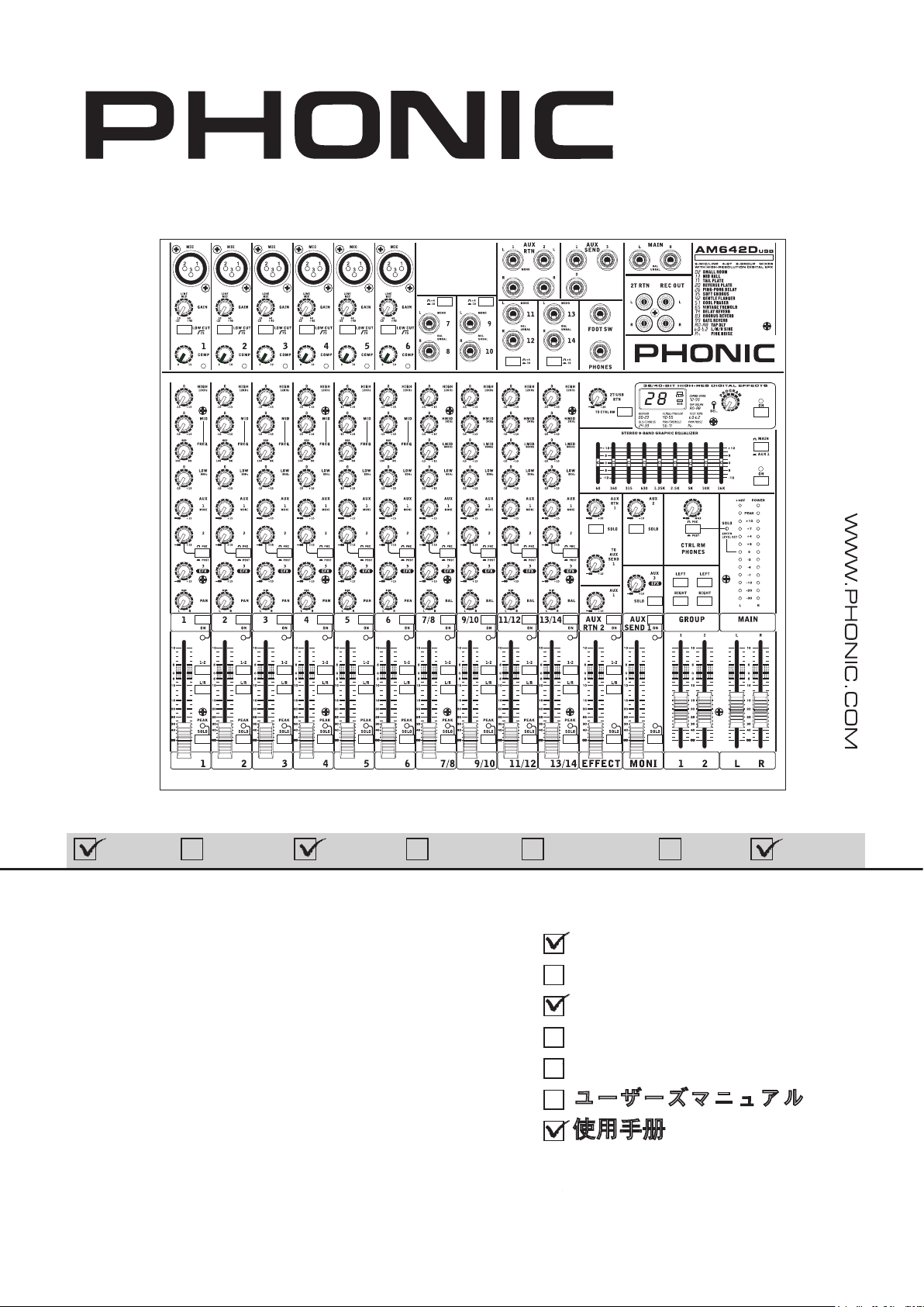
AM642D
USB
User's Manual
AM442D USB
Benutzerhandbuch
日本語
简体中文
AM642D USB
Manual del Usuario
Mode d'emploi
Manual do Usuário
ユーザーズマニュアル
使用手册
Page 2
English Deutsch Español Français Português
AM442D USB
AM642D USB
COMPACT MIXERS
MEZCLADORAS COMPACTAS
便携式调音台
ENGLISH ......................................I
日本語
简体中文
ESPAÑOL ......................................II
简体中文
......................................III
V1.0 08/29/2011
Page 3

USER'S MANUAL
CONTENTS
INTRODUCTION.....................................................................1
SYSTEM REQUIREMENTS................................................ ....1
GETTING STARTED................................................................1
CHANNEL SETUP....................................................................1
CO MPUTER CONNECT ION...... ......... ....................................1
MAKING CONNECTIONS.......................................................2
CONTROLS AND SETTINGS..................................................3
SPECIFICATIONS...................................................................7
APPENDIX
DIGITAL EFFECT TABLE.........................................................1
English Deutsch Español Français Português
APPLICATION.........................................................................2
DIMENSIONS..........................................................................4
BLOCK DIAGRAMS.................................................................5
Phonic preserves the right to improve or alter any information within this document without prior
notice.
日本語
简体中文
Page 4
English Deutsch Español Français Português
1. Read these instructions before operating this
apparatus.
2. Keep these instructions for future reference.
3. Heed all warnings to ensure safe operation.
4. Follow all instructions provided in this document.
5. Do not use this apparatus near water or in locations
where condensation may occur.
6. Clean only with dry cloth. Do not use aerosol or liquid
cleaners. Unplug this apparatus before cleaning.
7. Do not block any of the ventilation openings. Install
in accordance with the manufacturer’s instructions.
8. Donot install nearany heat sourcessuch asradiators,
heat registers, stoves, or other apparatus (including
.
9. Do not defeat the safety purpose of the polarized or
grounding-type plug. A polarized plug has two blades
with one wider than the other. A grounding type plug
has two blades and a third grounding prong. The wide
blade or the third prong is provided for your safety. If
the provided plug does not into your outlet, consult
an electrician for replacement of the obsolete outlet.
10. Protect the power cord from being walked on or
pinched particularly at plug, convenience receptacles,
and the point where they exit from the apparatus.
11. Only use attachments/accessories by the
manufacturer.
12. Use only with a cart, stand, tripod, bracket, or
table by the manufacturer, or sold with
the apparatus. When a cart is used, use caution
when moving the cart/apparatus
combination to avoid injury from tipover.
13. Unplug this apparatus during lighting
storms or when unused for long
periods of time.
14. Refer all servicing to service personnel.
Servicing is required when the apparatus has been
damaged in any way, such as power-supply cord or
plug is damaged, liquid has been spilled or objects
have fallen into the apparatus, the apparatus has
been exposed to rain or moisture, does not operate
normally, or has been dropped.
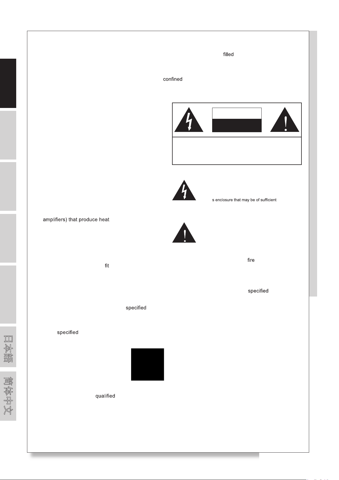
IMPORTANT SAFETY INSTRUCTIONS
CAUTION: TO REDUCE THE RISK OF ELECTRIC SHOCK,
DO NOT REMOVE COVER (OR BACK)
NO USER SERVICEABLE PARTS INSIDE
REFER SERVICING TO QUALIFIED PERSONNEL
The lightning flash with arrowhead symbol, within an
equilateral triangle, is intended to alert the user to the
presence of uninsulated“dangerous voltage”within the
product
’
magnitude to constitute a risk of electric shock to persons.
The exclamation point within an equilateral triangle is intended to alert the user to the presence of important operating and maintenance (servicing) instructions in the literature
accompanying the appliance.
WARNING: To reduce the risk of or electric shock, do
not expose this apparatus to rain or moisture.
CAUTION: Use of controls oradjustments orperformance
of procedures other than those may result in
hazardous radiation exposure.
The apparatus shall not be exposed to dripping or splashing and that no objects with liquids, such as vases,
shall be placed on the apparatus. The MAINS plug is used as the disconnect device, the disconnect device shall
remain readily operable.
Warning: the user shall not place this apparatus in the area during the operation so that the mains switch
can be easily accessible.
CAUTION
RISK OF ELECTRIC SHOCK
DO NOT OPEN
日本語
简体中文
Page 5
Introduction
Thank you for choosing one of Phonic’s many quality compact
mixers. The AM442D USB and AM642D USB mixers – designed
by the ingenious engineers that have created a variety of mixers
fantastic in style and performance in the past – display similar
proficiency that previous Phonic products have shown; with more
than a few refinements, of course. Featuring full gain ranges,
amazingly low distortion levels, and incredibly wide dynamic
ranges, these amazing mixers are bound to make a big impression
in any venue. The AM442D USB and AM642USB also offer a USB
interface for making stereo recordings on any modern Windows- or
Mac-based computer.
3. Move the Channel’s fader to around the 0 dB mark.
4. Pushing the channel’s SOLO button will send the audio
signal to the Control Room / Phones mixing bus and the
Level Meter will display the Control Room’s signal properties
(since the Main L/R mixing bus will receive no signal).
5. Set the gain so the level meter indicates the audio level is
around 0 dB.
6. This channel is now ready to be used; you can stop making
the audio signal.
7. You can now repeat the same process for other channels if
you wish.
English Deutsch Español Français Português
We know how eager you are to get started – wanting to get the
mixer out and hook it all up is probably your number one priority
right now – but before you do, we strongly urge you to take a look
through this manual. Inside, you will find important facts and figures
on the set up, use and applications of your brand new mixer. If
you do happen to be one of the many people who flatly refuse to
read user manuals, then we just urge you to at least glance at
the Instant Setup section. After glancing at or reading through the
manual (we applaud you if you do read the entire manual), please
store it in a place that is easy for you to find, because chances are
there’s something you missed the first time around.
System Requirements
Windows
Windows™ XP SP2, Vista™ or 7
Intel™ Pentium™ 4 processor or better
512 MB RAM (1 GB recommended)
Macintosh
Apple™ Mac™ OSX 10.5 or higher
G4™ processor or better
512 MB RAM (1 GB recommended)
Getting Started
1. Ensure all power is turned off on your mixer. To totally ensure
this, the AC cable should not be connected to the unit.
2. All faders and level controls should be set at the lowest
level and all channels switched off to ensure no sound is
inadvertently sent through the outputs when the device is
switched on. All levels can be altered to acceptable degrees
after the device is turned on.
3. Plug all necessary instruments and equipment into the
device’s various inputs as required. This may include line
signal devices, such as keyboards and drum machines, as
well as microphones and/or guitars, keyboards, etc.
4. Plug any necessary equipment into the device’s various
outputs. This could include amplifiers and speakers,
monitors, signal processors, and/or recording devices.
5. Plug the supplied AC cable into the AC inlet on the back of
the device and a power outlet of a suitable voltage.
6. Turn the power switch on.
Channel Setup
1. To ensure the correct audio level of the input channel is
selected, each of the Mixer’s Channel’s ON buttons should
be disengaged (which should turn the corresponding LED
indicator off – otherwise go back and try again), as well as
the SOLO buttons on each channel.
2. Ensure the channel you wish to set has a signal sent to it
similar to the signal that will be sent when in common use.
For example, if the channel has a microphone connected to it,
then you should speak or sing at the same level the performer
normally would during a performance; if a guitar is plugged
into the channel, then the guitar should also be strummed
as it normally would be (and so on). This ensures levels are
completely accurate and avoids having to reset them later.
Computer Connection
By simply connecting the USB cable provided along with your
AM442D USB or AM642D USB to the device and your Personal
Computer or Laptop, you are able to send CD quality (16-bit
stereo, with a 44.1 kHz sampling rate) signal to and from your
mixer. By doing this, you are actually turning your mixer into a
highly useful plug’n’play soundcard for your computer.
The USB sends an audio stream of the Main Left and Right
(record out) signal of your mixer to the computer. You can use
almost any dedicated Digital Audio Workstation (DAW) software
to record the signal from the AM mixer. You can also set the mixer
as your default audio device.
The USB interface also returns the audio signal from your computer
back to the 2T Returns, the signal of which is controlled by the 2T
/ USB Return control. If there are input signals from both the USB
interface and the 2T Return, the two signals are combined and
controlled simultaneously by the 2T return control.
Windows
1. Turn both the AM mixer and the computer on.
2. Connect the AM mixer to the computer via the provided USB
cable.
3. Let Windows find the device and install an appropriate
driver.
4. Enter the Control Panel and select Sounds and Audio
Devices.
5. When here, go to the Audio tab and select the “USB Audio
Codec” as your default sound recording and playback
device.
6. Depending whether you have Windows XP, Vista or 7, this
may differ slightly but the setting can always be found within
the Control Panel’s audio menu.
7. If you don’t want to use the AM442D USB and AM642D
USB as your default audio device, you can simply enter your
DAW or other audio program and select it as your default
device in the program only.
8. Be sure to set your minimum buffer settings to 64 samples
as to avoid clicks and pops.
Mac
1. Turn both the mixer and the computer on.
2. Connect the AM mixer to the computer via the provided USB
cable.
3. Enter the AUDIO MIDI SETUP menu.
4. Select the “USB Audio Codec” as your input and output
device.
5. Either the AM442D USB or AM642D USB is now your default
audio device.
6. Alternatively, enter your DAW software (or other relevant
audio program) and select the “USB Audio Codec” in the
device preferences.
7. Be sure to set your minimum buffer settings to 64 samples
as to avoid clicks and pops.
日本語
简体中文
AM442D USB / AM642D USB
1
Page 6
English Deutsch Español Français Português
Making Connections
Inputs and Outputs
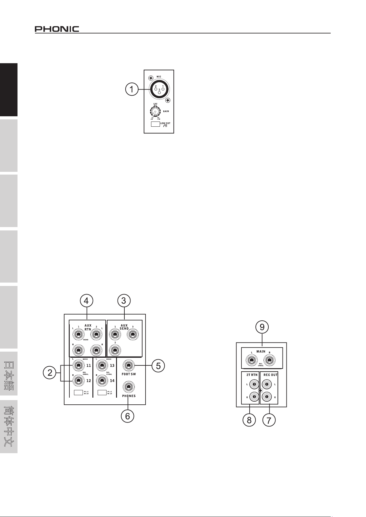
1. XLR Microphone Jacks
These jacks accept typical 3-pin XLR
inputs for balanced and unbalanced
signals. They can be used in
conjunction with microphones – such
as professional condenser, dynamic
or ribbon microphones - with standard
XLR male connectors, and feature low
noise preamplifiers, serving for crystal
clear sound replication. The AM442D
USB mixer features five standard
XLR microphone inputs, whereas the
AM642D USB features a total of eight.
NB. When these inputs are used with condenser microphones, the
Phantom Power should be activated. However, when Phantom Power is
engaged, single ended (unbalanced) microphones and instruments should
not be used on the Mic inputs.
2. Stereo Channels
The AM442D USB and AM642D USB feature a few stereo
channels, thrown in for maximum flexibility. Each of these stereo
channels features two 1/4” phone jacks, for the addition of
various line level input devices, such as electronic keyboards,
guitars and external signal processors or mixers. If you wish to
use a mono device on a stereo input, simply plug the device’s
1/4” phone jack into the left (mono) input and leave the right input
bare. The signal will be duplicated to the right due to the miracle
of jack normalizing.
3. AUX Sends
These 1/4” TS outputs may be used to connect to an external
signal processor, or even to an amplifier and speakers (depending
on your desired settings) from the mixer. The signal from the AUX
Sends is controlled by the main AUX and EFX controls (on the
face of the mixer), which obtain their signal from the AUX and
EFX controls located on each channel strip. The AM442D USB
features 2 AUX sends, whereas the AM642D USB features a total
of 3.
4. AUX Returns
These 1/4” TS inputs are for the return of audio to the AM442D
USB and AM642D USB mixers, processed by an external signal
processor. If really needed, they can also be used as additional
inputs. The feed from these inputs can be adjusted using the
AUX Return controls on the face of the mixer. When connecting
a monaural device to the AUX Return 1 and 2 inputs, simply plug
a 1/4” phone jack into the left (mono) input, and the signal will
appear in the right as well. This, however, does not work for the
AUX Return 3 input on the AM442D USB.
NB. When any device is plugged into the mixer’s corresponding EFX
Return inputs (ie. AUX Return 2), the mixer’s internal digital effect engine
is then disabled.
5. Foot Switch Jack
These ports are for the inclusion of a foot switch, used to remotely
switch the built-in Digital Effect processor between the on and
standby modes.
6. Phones
This stereo output port is suited for use with headphones, allowing
monitoring of the mix. The audio level of this output is controlled
using the Control Room / Phones control.
7. 2T Record / Record Out
These outputs will accommodate RCA cables, able to be fed to
a variety of recording devices. Also included is a mini stereo jack
for the addition of recording devices such as MD players, and
even laptop computers.
8. 2T Return
These RCA inputs are used to connect the mixer with parallel
external devices, such as sub mixers or external effect processors,
receiving the processed signal from another source and feeding it
to either the Main L and R or the Phones mixing bus.
9. Main Out
These two 1/4” phone jacks will output the final stereo line level
signal sent from the main mixing bus. The primary purpose of
these jacks is to send the main output to external devices, which
may include power amplifiers (and in-turn, a pair of speakers),
other mixers, as well as a wide range of other possible signal
processors (Equalizers, Crossovers, etcetera).
日本語
简体中文
2
AM442D USB / AM642D USB
Page 7
Rear Panel
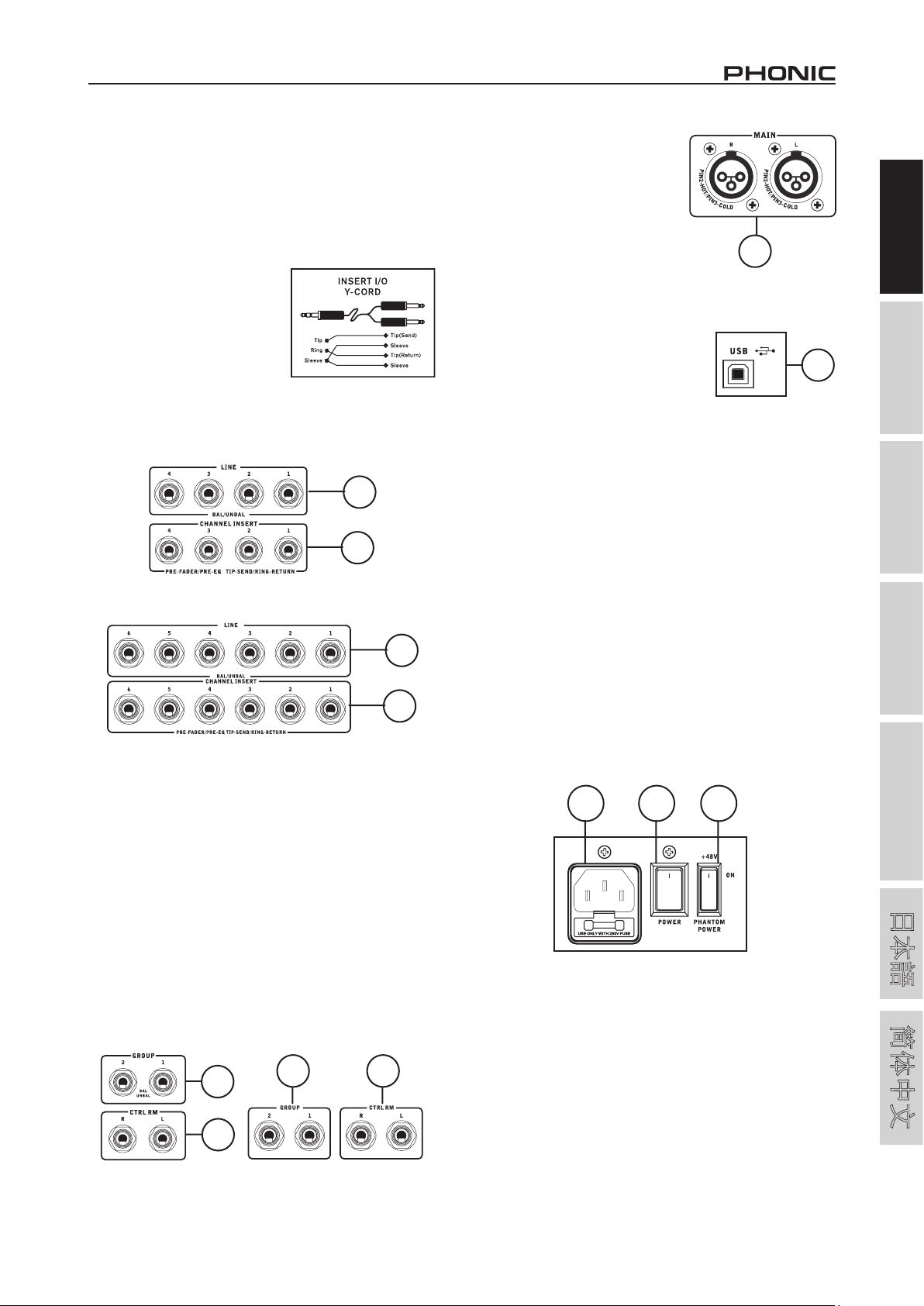
10. Line Inputs
These inputs accept typical 1/4” TRS balanced or TS unbalanced
inputs, for balanced or unbalanced signals. There are various
numbers of these inputs depending which mixer you are using.
They can be used in conjunction with a wide range of line level
devices, such as keyboards, drum machines, electric guitars, and
a variety of other instruments.
11. Channel Inserts
Located on the rear of the
AM442D USB and AM642D USB,
the primary use for these TRS
phone jacks is for the addition of
external devices, such as dynamic
processors or equalizers, to the
mono input channels on both of
these units. This includes channels
1 to 4 on the AM442D USB and
channels 1 to 6 of the AM642D USB. This will require a Y cord
that can send (pre-fader and pre-EQ) and receive signals to and
from an external processor.
10
11
AM442D
USB
10
11
AM642D
USB
14. Main Out
These two XLR ports will output
the final stereo line level signal
sent from the main mixing bus. The
primary purpose of these jacks is
to send the main output to external
devices, which may include power
amplifiers (and in-turn, a pair of
speakers), other mixers, as well
as a wide range of other possible
signal processors (equalizers,
crossovers, etcetera).
15. USB Port
This USB connector can be used
to connect the AM442D USB and
AM642D USB to any modern Windows
or Mac-based computer. Doing so will
allow users to get a stereo signal both
to and from the computer.
16. Phantom Power Switch
When this switch is in the on position, it activates +48V of
phantom power for all microphone inputs, allowing condenser
microphones (well, the ones that don’t use batteries) to be
used on these channels. Activating Phantom Power will be
accompanied by an illuminated LED above the left channel Level
Meter. Before turning Phantom Power on, turn all level controls
to a minimum to avoid the possibility of a ghastly popping sound
from the speakers.
NB. Phantom Power should be used in conjunction with balanced
microphones. When Phantom Power is engaged, single ended
(unbalanced) microphones and instruments should not be used on the
Mic inputs. Phantom Power will not cause damage to most dynamic
microphones, however if unsure, the microphone’s user manual should
be consulted.
17. Power Switch
This switch is used to turn the mixer on and off.
18. Power Connector
This port is for the addition of a power cable, allowing power to be
supplied to the mixer. Please use the power cable that is included
with this mixer only.
14
15
English Deutsch Español Français Português
12. Control Room Outputs
These two 1/4” phone jack outputs feed the signal altered by the
Control Room / Phones level control on the face of the mixer. This
output has extensive use, as it can be used to feed the signal
from the mixer to an active monitor, for the monitoring of the
audio signal from within a booth, or, alternatively, for the addition
of external signal processing devices or mixers, as well as acting
as a “side fill” output, supplying audio to indoor areas that the
main speakers do not reach.
13. Group Out
These 1/4” phone jacks output the final feed from the Group 1
and 2 faders on the main mixer. These outputs can be used to
feed a wide range of devices, such as mixers, signal processors,
and even to connect an amplifier and speakers to be used along
with the Main Speakers, for a more rounded audio experience.
13
13
12
12
AM442D
AM442D USB / AM642D USB
USB
AM642D
USB
18
17
16
Controls and Settings
Channel Controls
19. Line/Mic Gain Control
This controls the sensitivity of the input signal of the Line/
Microphone input. The gain should be adjusted to a level that
allows the maximum use of the audio, while still maintaining the
quality of the feed. This can be accomplished by adjusting it to a
level that will allow the peak indicator occasionally illuminate.
20. Low Cult Filter (75 Hz)
This button will activate a high-pass filter that reduces all
frequencies below 75 Hz at 18 dB per Octave, helping to remove
any unwanted ground noise or stage rumble.
3
日本語
简体中文
Page 8
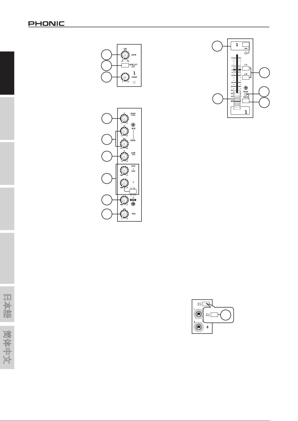
21. Compressor Control and Indicator
This controls the onboard compressor
function on mono channels. Turning
this control up towards the 12 o’clock
English Deutsch Español Français Português
日本語
简体中文
position will adjust the threshold and
ratio of the compressor at varying
degrees. Once you reach the 12
o’clock position, the control will then
adjust the compression settings along
with an onboard expander (or, in other
words, a compander). The LED that
accompanies this control will light up
when the compressor is triggered.
22. High Frequency Control
This control is used to give a shelving
boost or cut of ±15 dB to high frequency
(12 kHz) sounds. This will adjust the
amount of treble included in the audio
of the channel, adding strength and
crispness to sounds such as guitars,
cymbals, and synthesizers.
23. Middle Frequency Control
This control is used to provide a peaking
style of boost and cut to the level of
middle frequency sounds at a range of
±15 dB. These mixers also provide a
sweep control, allowing you to select a
center frequency between 100 Hz and
8 kHz. Changing middle frequencies
of an audio feed can be rather difficult
when used in a professional audio mix,
as it is usually more desirable to cut
middle frequency sounds rather than
boost them, soothing overly harsh vocal
and instrument sounds in the audio.
The stereo channels of the AM442D
USB and AM642D USB mixers feature
a High-Mid and Low-Mid control
instead of the typical controls described above. They provide a
peaking style of boost and cut to middle frequencies, where the
frequencies are set at 3 kHz and 800 Hz (High-Mid is set at 3 kHz
and Low-Mid is set at 800 Hz).
24. Low Frequency Control
This control is used to give a shelving boost or cut of ±15 dB to
low frequency (80 Hz) sounds. This will adjust the amount of bass
included in the audio of the channel, and bring more warmth and
punch to drums and bass guitars.
25. AUX Control and Pre/Post Button
This control alters the signal level that is being sent to the AUX 1
mix, the signal of which is suitable for connecting stage monitors,
allowing artists to listen to the music that is being playing. Also
included is a Pre/Post button, which alternates the feed to the
AUX mix between a post- and pre-fader feed. The AM642D USB
features a second AUX send mix, and thus offers a second AUX
control.
26. EFX Control
This control alters the signal level that is sent to the EFX send
(AUX 2 or 3) output and the built-in digital effect processor. The
EFX send signal can be used in conjunction with external signal
processors (this signal of which can be returned to mixer via the
AUX return input), or simply as an additional auxiliary output.
19
20
21
22
23
24
25
26
27
28. On Button and Indicator
This turns the channel on,
allowing the user to use
the feed from the channel’s
inputs to supply the MAIN L/
R, GROUP 1/2, AUX and EFX
buses. The corresponding
indicator will be illuminated
when turned on.
29. 1-2 and L-R Buttons
These handy buttons allow
you to decide the audio
path of the corresponding
channel. Pushing the “1-2”
button allows the signal to
be sent to the Group 1-2 mix,
where the “L-R” allows it to
be sent to the Main L-R mix.
30. Peak Indicator
This LED indicator will illuminate when the channel hits high
peaks, 6 dB before overload occurs. It is best to adjust the
channel level control so as to allow the PEAK indicator to light
up on regular intervals only. This will ensure a greater dynamic
range of audio.
31. Solo Button
The Solo button is pushed to allow the signal of a corresponding
channel to be sent to the Control Room / Phones control (pre
or post fader, depending on the properties selected by the pre /
post button, located by the Control Room / Phones control), for
use with either headphones or studio monitors. This also allows
easier setting of the input gain and tracking of audio by sound
engineers. The corresponding green LED will illuminate when the
Solo button is engaged.
32. Channel Level Fader
This control will alter the signal level that is sent from the
corresponding channel to the main mixing bus.
33. +4 / -10 Buttons
These buttons, located on each stereo input channel, are used
adjust the input sensitivity of the corresponding channel, which
will adapt the mixer to external devices which may use different
operating levels. If the input source is -10 dBu (consumer audio
standard), it is best to engage the switch, allowing the signal to be
heard. If the input source is +4 dbV (professional audio standard)
the corresponding input channel’s button should be disengaged
to ensure the integrity of the Mixer’s circuitry. If you are unsure
of the source’s operating level, we suggest leaving the switch
disengaged until you test the source’s signal. You can then
engage if necessary (if the level of input is obviously too low).
28
32
29
30
31
33
27. Pan / Balance Controls
This alternates the degree or level of audio that the left and right
side of the main mix should receive. On mono channels, the PAN
control will adjust the level that the left and right should receive
(pan), where as on a stereo channel, adjusting the BAL control will
attenuate the left or right audio signals accordingly (balance).
4
AM442D USB / AM642D USB
Page 9
Digital Effect Engine
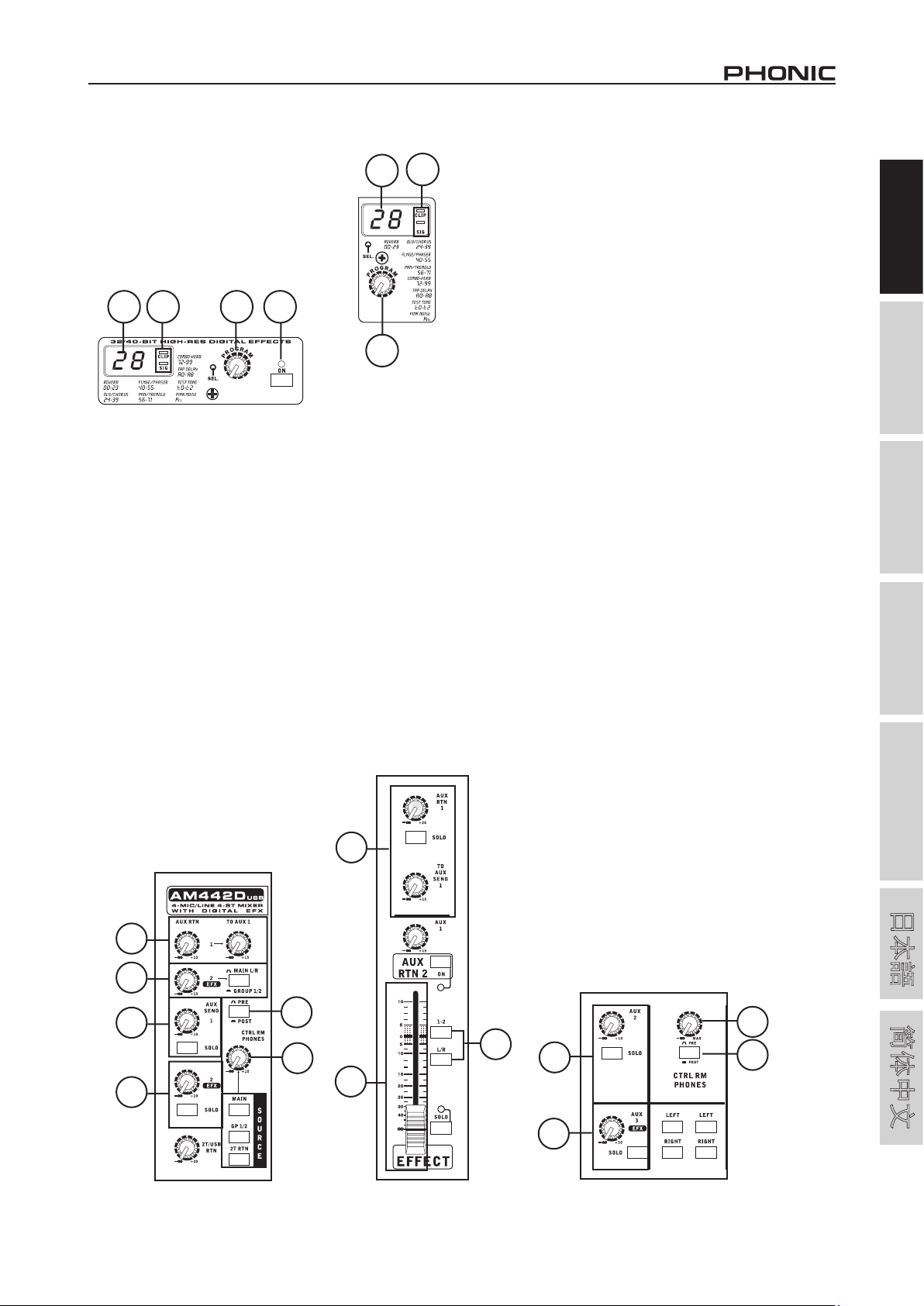
34. Digital Effect Display
This 2-digital numeric display shows the
program number that is currently applied
to your EFX audio signal. When you rotate
the Program control, you can scroll through
different program numbers; however the
display will revert back to the original program
if a new program is not selected within a
few seconds. For a list of available effects,
please observe the Digital Effect Table.
34 35
36 37
34
35
36
AM442D USB
AM642D USB
35. Sig and Clip Indicators
Located within the Digital Effect Display are Clip and Sig LEDs.
The Sig LED will light up when any signal is received by the effect
processor, and the Clip LED will light up shortly before excessive
signals are dynamically clipped. If the Clip LED lights up too often,
it may be advisable to turn down the AUX 3/EFX control on one or
all input channels to ensure the signal level is not excessive.
36. Program Control
This control is used to scroll through the various effects. Turning
the control clockwise will allow users to ascend into higher
program numbers, and turning it counter-clockwise will allow
users to descend into lower program numbers. Pushing this
control will apply the new effect. When a tap-delay effect is
selected, pressing this control will allow users to select the tapdelay time.
By pushing the button several times, the effect processor
interprets the time between last two pushes and remembers this
as the delay time – until the button is pushed again. This is kept
even after the power is turned off. When the tap delay effect is
selected, a small LED will flash within the digital effect display
window at the selected intervals.
37. Effect On Button (AM642D USB)
This button is pushed to turn the corresponding effect panel on
or off. When effects are bypassed, there will be 2 flashing LEDs
in the effect display. This button is not featured on the AM442D
USB. Users must use a footswitch to activate and deactivate
effects on this model.
Master Section
38. AUX Return Controls
These controls adjust the signal level of audio fed through to the
stereo AUX Return inputs, which will be added to the main mix.
The two “To AUX” controls adjust the post-fader level of the signal
from the AUX Return control to the AUX 1 mix.
On the AM642D USB, the AUX return control also features
a SOLO button, which sends the signal to the Control Room /
Phones mixing bus, most commonly for monitoring.
39. EFX Return Control
This control adjusts the signal level of audio fed through to stereo
AUX Return 2 inputs. If no device is plugged into the AUX Return
2 inputs, this control then acts as the final level control of the
built-in Digital Effect Engine. The signal of this control is sent to
the appropriate mixing bus, as selected by the Main L-R / Group
1-2 button.
On the AM642D USB, the EFX return control is a little different,
as it is, in fact, a 6 mm fader, and takes its feed from AUX Return
2. Along with what was already stated above, the AM642D USB’s
also features a SOLO button (with indicator), which sends the
signal to the Control Room / Phones mixing bus; an L-R button,
which allows you to send the EFX Return post-fader signal to the
Main Left and Right mixing bus; and a 1-2 button, allowing you
to send the EFX Return post-fader signal to the Group 1 and 2
mix.
40. Main L/R - Group 1/2 Button
This button changes the destination of the signal sent from the
AUX Return 1 through to AUX Return 3 mixing buses between
the Main L/R and Group 1/2 mixing buses.
41. AUX Send Master Controls
These controls adjust the final level of the AUX mixes (as
taken from the AUX level controls on each channel strip), the
audio of which is sent to corresponding AUX send outputs. The
corresponding SOLO button allows you to send the AUX Send
signal to the Control Room / Phones mixing bus. The AM442D
USB offers one AUX send, while the AM642D USB offers two
(excluding the EFX sends, of course). The AM642D USB’s AUX 1
send is a 60 mm fader and also features an on/off button.
English Deutsch Español Français Português
38
39
41
42
AM442D USB
AM442D USB / AM642D USB
44
43
38
39
AM642D USB
42. EFX Send Master Control
This control adjusts the final level of the EFX mixing bus (as taken
from the EFX level controls on each channel strip), the audio of
which is sent to the AUX Send 2 (on the AM442D USB) and the
AUX Send 3 (on the AM642D USB) outputs, as well as the built-in
digital effect processor. The corresponding SOLO button allows
you to send the signal to the Control Room / Phones mixing bus.
43
40
41
44
42
AM642D USB
5
日本語
简体中文
Page 10
English Deutsch Español Français Português
AM442D USB
46
AM642D USB
46
43. Control Room / Phones Controls
This control is used to adjust the audio level of the phones feed,
as well as the signal sent to the Control Room output, for use
in monitoring, as side fill, or for the addition of other, external
devices.
44. Pre / Post Control
This button alternates the Control Room / Phones source signals
between those of post-fader and pre-fader feeds.
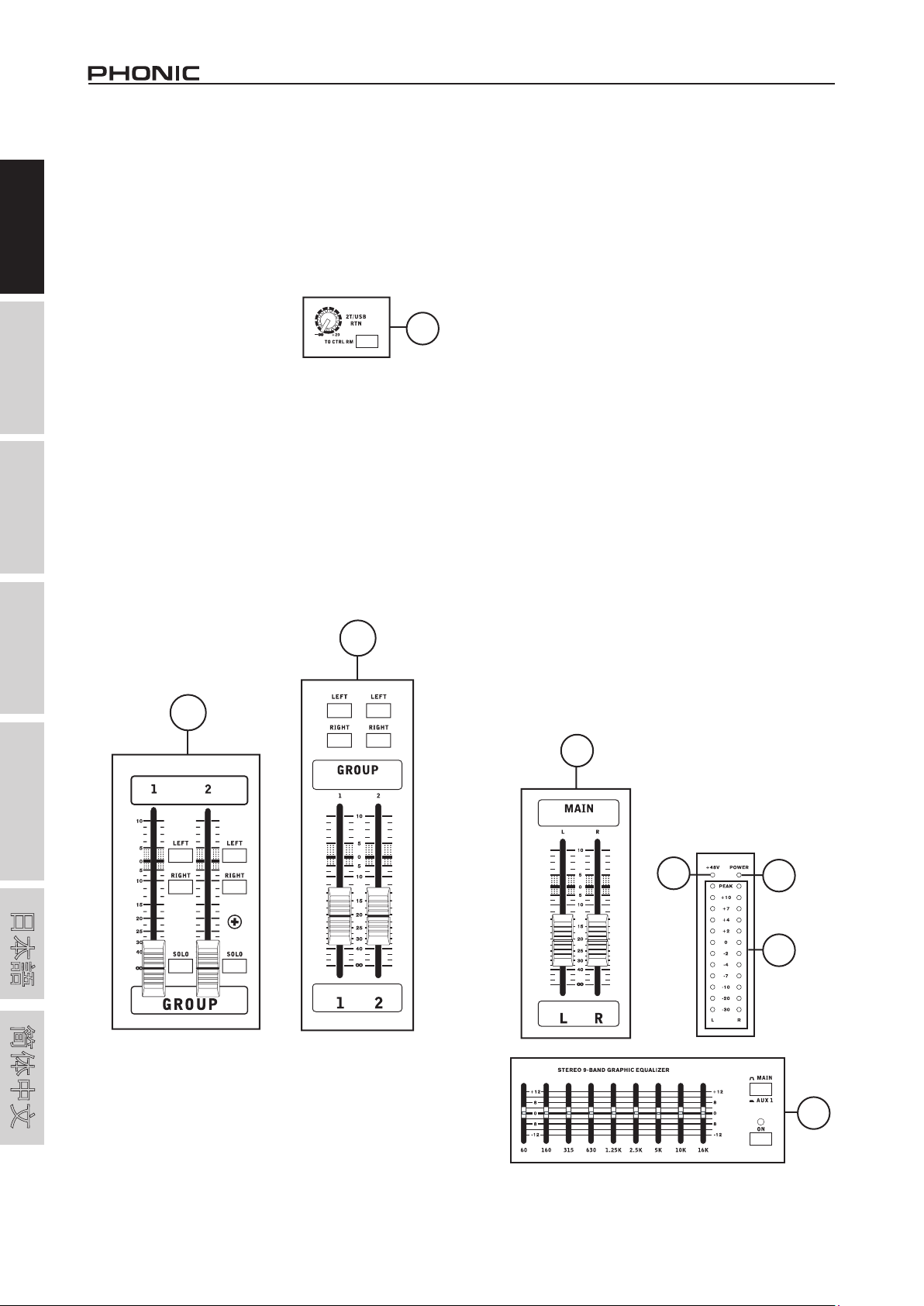
45. 2T / USB Return Controls
Turning the 2T Return level control
adjusts the signal level of the feed
from the 2T return inputs, as well as
the USB return signal. These signals
will then be fed to the Main stereo
mix. The “to Ctrl Rm” button, found
on the AM642D USB only, sends the
signal to the Control Room/Phones
mix.
46. Group 1/2 Controls
These two faders are the final level control for the Group 1 and 2
audio feeds, sent to the Group 1 and 2 outputs. These faders can
be fed a signal from the various mono and stereo channels, as
well as AUX and EFX returns, depending on the your selections.
When pushed all the way up, these faders provide 10 dB of gain
to the signal, and, when set all the way down, effectively mute
the signal. The Group 1/2 Controls also feature Left and Right
buttons, which allow you to send the Group 1/2 post-fader signals
to the Main left and right mixes (as selected). The AM442D USB
also features a Solo button on each Group.
45
47. Main L/R Faders
These two faders are the final level control for the Main Left
and Right audio feeds, sent to the Main L and R outputs. These
faders are possibly fed by the various mono and stereo channels,
as well as AUX and EFX returns and 2T inputs, depending on
the your selections. When pushed all the way up, these faders
provide 10 dB of gain to the signal, and, when set all the way
down, effectively mute the signal.
48. +48V Indicator
This indicator will illuminate when Phantom Power is activated.
49. Power Indicator
The Power Indicator will light up when the power of the mixer is
on; in case you weren’t too sure.
50. Level Meter
These dual 11- or 12-segment level meters give an accurate
indication of when audio levels of the Main L/R output
signals reach certain levels. The 0 dB indicator illuminates is
approximately equal to an output level of +4 dBu, and the PEAK
indicator illuminates about 6 dB before the signal is dynamically
clipped. It is suggested for the maximum use of audio to set the
various levels controls so that it sits steadily between 0 and 8 dB
to make full use of audio, while still maintaining fantastic clarity.
When no signal is being fed through the Main L/R mixing bus, the
level meter will then display the audio properties of the Control
Room / Phones feed. This is especially helpful when setting the
levels of each individual channel, as is shown in the Channel
Setup section of this manual. The “Solo” button will illuminate
when the Level Meter displays the audio properties of the Control
Room / Phones signal.
日本語
简体中文
51. Graphic Equalizer (AM642D USB only)
This stereo 9 band graphic equalizer allows the user to adjust
the frequency response of a signal, with a maximum of ±12 dB of
signal boost or cut for each of the frequencies. The AUX 1 / MAIN
switch alternates the use of the equalizer between the use of the
AUX 1 bus and MAIN L/R bus signals. Pushing the on button in
activates the equalizer, which is accompanied by an illuminated
LED.
47
48
49
50
6
51
AM642D USB
AM442D USB / AM642D USB
Page 11
SPECIFICATIONS
AM442D USB AM642D USB
Inputs
Total Channels 8 10
Balanced Mono Mic / Line Channel 5 6
Balanced Mic / Stereo Line channel - 2
Balanced Stereo Line Channel 3 2
AUX Return 3 stereo 2 stereo
2T Input Mini stereo and stereo RCA Mini stereo and stereo RCA
Outputs
Main L/R Stereo 2 x 1/4” TRS, Bal. & 2 x XLR 2 x 1/4” TRS, Bal. & 2 x XLR
Group 2 2
Rec Out Mini stereo and stereo RCA Mini stereo and stereo RCA
CTRL RM L/R 2 x 1/4” TS 2 x 1/4” TS
Phones 1 1
Channel Strips 8 10
EFX Send 2 3
Pan/Balance Control Yes Yes
Volume Controls 60mm fader 60mm fader
Inserts 5 6
Master Section
Phones Level Control Yes Yes
Main L/R Level Control 60 mm fader 60 mm fader
Level Meter 13-segment 13-segment
Phantom Power Supply +48V DC +48V DC
Frequency Response (Mic input to any output)
20Hz ~ 60KHz +0/-1 dB +0/-1 dB
20Hz ~ 100KHz +0/-3 dB +0/-3 dB
Crosstalk (1KHz @ 0dBu, 20Hz to 20KHz bandwidth,
channel in to main L/R outputs)
Channel fader down, other channels at unity <-90 dB <-90 dB
Noise (20Hz~20KHz; measured at main output, Chan-
nels 1-4 unit gain; EQ flat; all channels on main mix;
channels 1/3 as far left as possible, channels 2/4 as
far right as possible. Reference=+6dBu)
Master @ unity, channel fader down -86.5 dBu -86.5 dBu
Master @ unity, channel fader @ unity -84 dBu -84 dBu
S/N ratio, ref to +4 >90 dB >90 dB
Microphone Preamp E.I.N. (150 ohms terminated,
max gain)
THD (Any output, 1KHz @ +14dBu, 20Hz to 20KHz,
channel inputs)
CMRR (1 KHz @ -60dBu, Gain at maximum) 80dB 80dB
Maximum Level
Mic Preamp Input +10dBu +10dBu
All Other Input +22dBu +22dBu
Balanced Output +28dBu +28dBu
Impedance
Mic Preamp Input 2 K ohms 2 K ohms
All Other Input (except insert) 10 K ohms 10 K ohms
RCA 2T Output 1.1 K ohms 1.1 K ohms
<-129.5 dBm <-129.5 dBm
<0.005% <0.005%
English Deutsch Español Français Português
日本語
简体中文
AM442D USB / AM642D USB
7
Page 12
English Deutsch Español Français Português
Equalization 3-band, +/-15dB 3-band, +/-15dB
Low EQ 80Hz 80Hz
Mid EQ 100-8k Hz, sweepable 100-8k Hz, sweepable
L-Mid EQ 800 Hz 800 Hz
H-Mid EQ 3 kHz 3 kHz
Hi EQ 12 kHz 12 kHz
Low Cut Filter 75 Hz (-18 dB/oct) 75 Hz (-18 dB/oct)
USB Audio Stereo In/Out Stereo In/Out
Connector Type USB Type B USB Type B
Bitrate 16-bit 16-bit
Sampling Rate 48 kHz 48 kHz
Digital Effect Processor 100 effects with tap delay control and
test tones
Footswitch EFX on/off EFX on/off
Power Requirements 100-240 VAC, 50/60 Hz 100-240 VAC, 50/60 Hz
Weight 8.40 lbs (3.81 kg) 10.6 lbs (4.8 kg)
Dimensions (WxHxD) 11.8” x 4.1” x 13.6”
(300 x 104.5 x 346 mm)
100 effects with tap delay control
and test tones
16” x 4.12” x 14”
(407 x 103.5 x 357 mm)
日本語
简体中文
8
AM442D USB / AM642D USB
Page 13

Manual del Usuario
CONTENIDO
INTRODUCCIÓN.....................................................................1
REQUISITOS DEL SISTEMA...................................................1
COMENZANDO.......................................................................1
CONFIGURACIÓN DEL CANAL..............................................1
CONECCIONES DE LA COMPUTADORA..............................1
HACER CONEXIONES............................................................2
CONTROLES Y CONFIGURACIONES...................................4
ESPECIFICACIONES..............................................................7
APéNDICE
TABLA DE EFECTO DIGITAL..................................................1
APLICACIÓN...........................................................................2
English Deutsch Español Français Português
DIMENSIONES........................................................................4
DIAGRAMAS DE BLOQUE......................................................5
Phonic se reserva el derecho de mejorar o alterar cualquier información provista dentro
de este documento sin previo aviso.
日本語
简体中文
Page 14

English Deutsch Español Français Português
日本語
简体中文
Page 15

INTRODUCCIÓN
Felicitaciones por la compra de una de las muchas mezcladoras
compactas de calidad Phonic. Las mezcladoras AM442D USB y AM442D USB y
AM642D USB son dise�adas por nuestros talentosos ingenieros�adas por nuestros talentosos ingenieros
que han creado desde antes hasta ahora una gran variedad de
mezcladoras fantásticas de estilo y de ejecución. Esto demuestra
el potencial que los productos previos han demostrado con
algunas actualizaciones, claro. La serie completa de AM
figura con gama de ganancia completa, niveles de distorsión
formidables y una increíble gama dinámica ancha que ofrece
estas peque�as unidades en cualquier local. Las mezcladoras
AM442D USB y AM642D USB ofrecen una interfase USB para
hacer grabaciones de estéreo en cualquier computador con base
de Windows o Mac.
Sabemos que usted esta ansioso de comenzar, sacando su
mezcladora y instalándola es lo que ahorita desea hacer como
lo primero. Pero antes de comenzar, le recomendamos que
tome un poco de tiempo y lea este manual. Ya que dentro usted
encontrará información importante junto con gráficas para la
instalación, usos y aplicaciones para su nueva mezcladora. Si
usted es el tipo de persona quien se reusa leer este manual,
entonces le pedimos que se lea la sección de Instalación Básica
y después de haberlo leído (gran plauso si se ha leído todo el
manual completo.) Favor guarde este manual en un lugar de
acceso fácil de encontrar, para por si acaso lo requiere para
cualquier consulta o detalles que usted se haya olvidado antes.
REQUISITOS DEL SISTEMA
Windows
Windows™ XP SP2, Vista™ o 7
Procesador Intel™ Pentium™ 4 o más alta
512 MB RAM (1 GB recomendado) recomendado))
Macintosh
Apple™ Mac™ OSX 10.5 o más alta™ Mac™ OSX 10.5 o más altaMac™ OSX 10.5 o más alta™ OSX 10.5 o más alta OSX 10.5 o más alta
Procesador G4™ o mejor
512 MB RAM (1 GB recomendado)
COMENZANDO
1. Asgurese que toda fuente de poder de su mezcladora esté
apagado. Para estar completamente seguro de este paso,Para estar completamente seguro de este paso,
favor de no conectar el cable AC de la unidad.
2. Todos los faders y controles de nivel deben estar fijados al
nivel minimo y todos los canals deben estar apgagados para
asegurar que ningun sonido sea enviado inadvertidamente
por las salidas cuando el dispositivo esté encendido. TodolosTodo los
niveles pueden ser alternados a grados aceptables depués
de que la unidad este encendida.
3. Conecte todos los instrumentos y equipo necesario en las
varias entradas del dispositivo. Esto pude incluir unidades de
se�al, tales como teclados, maquinas de tambor, micrófonos,
guitarras y más.
4. Conecte cualquier equipo necesario a las varias salidas del
dispositivo. Esto puede incluir amplificadores, altavoces, monitores, procesadores de se�al o unidades de grabación.
5. Conecte el cable AC ofrecido dentro de la entrada AC detrás
del dispositivo y un enchufe de voltaje apropiado.
6. Encienda el fuente de pode.
CONFIGURACIÓN DEL CANAL
1. Para asegurar el nivel de audio correcto de la entrada del
canal que es seleccionado, cada botón ON del canal de la
mezcladora debe estar desconectada (debe desconectar
el indicador LED correspondiente, sino vuelva hacer este
proceso nuevamente) al igual que botón SOLLO en cada
canal.
2. Asegure que el canal que usted quiere configurar tenga
se�al de envío similar a la se�al que será enviado para uso
común. Por ejemplo, si el canal tiene micrófonos conectados,
entonces usted debe hablar o cantar al mismo nivel que
normalmente haría en la presentación. Si una guitarra es
conectada dentro del canal, igualmente debe conectar como
siempre lo hace. Esto es para asegurar completamente la
exactitud para evitar re-configuraciones luego.
3. Mueva los deslizadores de los canales y marquelo alrededor
de 0 dB.
4. Presione el botón SOLO enviará dicha se�al audio a la
Sala de Control/Fusiones bus Phones y el medidor de nivel
mostrará las propiedades de se�al de la Sala de Control (ya
que fusión bus Central I/D no recibirá ninguna se�al).
5. Fije la ganancia al medidor del nivel indicado de audio nivel
alrededor de 0 dB.
6. Este canal está ahora listo para ser usado, puede dejar de
hacer se�al de audio.
7. Ahora también puede repetir el mismo proceso para los otros
canals que quiera.
CONECCIONES DE LA COMPUTADORA
Simplemente conecte el cable de USB que le ofrecemos con su
AM442D USB o AM642D USB a su computadora personal o portátil, usted podrá enviar se�ales de calidad CD (16-bit estéreo con
44.1 KHz frecuencia de muestreo) a su mezcladora. En ejecutar
este proceso usted está convirtiendo su AM442D USB y AM642D
USB en una tarjeta de sonido altamente eficiente para conectar y
usar desde su computadora.
El USB envía un flujo de audio se�al al Central izquierdo y derecho
(record out) de su mezcladora a la computadora. Usted puede
emplear cualquier programa de Didigtal Audio Workstation (DAW)
para grabar la se�al desde su mezcladora AM. Usted también
configurarlo la unidad con audios predeterminados. El interfase
USB también retorna las se�ales audio desde su computadora al
2T Retorno, se�al que es controlada por 2T/USB control retorno.
Si hay se�ales de entrada provenientes de ambos interfases USB
y 2T Retorno, las dos se�ales son combinadas y contraladas
simultáneamente por el control de 2T retorno.
Windows
1. Encienda su mezcladora AM y computadora.
2. Conecte la mezcladora AM a al computadora por medio del
cable USB que le ofrecemos.
3. Espere que Windows localice la unidad e instale el driver
apropiado.
4. Entre al Panel de Control y seleccione los dispositivos de
Sonido y Audio.
5. En esta etapa elija el Audio tab y seleccione el “USB Audio
Codec” como su sonido de grabación predeterminado y
dispositivo de reproducción.
6. Dependiendo si usted usa Windows XP, Vista o 7, habrá
diferencias pero la configuración siempre se podrá encontrar
en el menú del Panel de Control Audio.
7. Si usted no desea usar su AM como el dispositivo predeterminado de audio, simplemente entre en su DAW u otro programa de audio y seleccione su dispositivo predeterminado
en el programa solamente.
8. Asegúrese de que la configuración minima de su buffer este
fijada en 64 muestreos (samples) para evitar clicks y pops.
Mac
1. Encienda el su mezcladora AM442D USB y AM642D USB y
la computadora.
2. Conecte la mezcladora AM a la computadora por medio del
cable USB que le ofrecemos.
3. Entre al menú AUDIO MIDI SETUP.
4. Seleccione el “USB Audio Codec” como su dispositivo de
entrada y salida.
5. Ahora el AM442D USB o AM642D USB es ahora su dispositivo audio predeterminado.
6. Alternativamente, entre a su programa de DAW (u otro
programa de audio) y seleccione “USB Audio Codec” en el
dispositivo de preferencia.
7. Asegúrese de que la configuración minima de su buffer este
fijada en 64 muestreos (samples) para evitar clicks y pops.
English Deutsch Español Français Português
日本語
简体中文
AM442D USB / AM642D USB
1
Page 16

English Deutsch Español Français Português
HACER CONEXIONES
Entradas y Salidas
1. Jacks de Micrófono XLR
Estos jacks aceptan entradas tradicionales de 3-pin XLR para se�ales
balanceadas y desbalanceadas. Pueden
ser usados en conjunto con micrófonos
tales como condensadores profesionales, dinámica o micrófono de cinta con
conectores machos estándar XLR y
figuran preamplificadores de bajo ruido
que ofrecen replica de sonido claro
cristalino. La mezcladora AM442D USB
figura cinco entradas de micrófono
estándar XLR y para el AM624D USB
figuran el toral de ocho.
NB. Cuando estas entradas están usadas con micrófonos de condensador,
dicha Potencia Fantasma debe ser activada. Sin embargo, cuando esta
potencia está conectada a un terminal solo (desbalanceado) de micrófonos
o instrumentos no se debe de usar entradas de Mic.
2. Canales Estéreo
El AM442D USB y AM642D USB figura unos canals estéreo para
máxima flexibilidad. Cada uno de estos canales estéreo figuran
dos phone jacks de 1/4” para a�adir varios niveles de líneas de
entrada de dispositivos, tales como teclados electrónicos, guitarras
y procesadores de se�al externo o mezcladoras. Si usted desea
usar una unidad mono en una entrada de retorno estéreo, simplemente conecte el jack phone1/4” dentro del estéreo izquierdo
(mono) y deje la entrada derecha libre. Esta se�al se duplicará al
derecho debido a la normalización del jack.
3. Envíos AUX AUX
Estas salidas de 1/4” TS pueden ser utilizados para conectar un
procesador de se�al externo o un amplificador y altavoz (dependiendo de su configuración) desde la mezcladora. La se�al del
envío AUX es controlada por los controles de AUX y EFX principal
(en la superficie de la unidad), que obtiene dicha se�al desde
los controles AUX y EFX ubicados en cada franja de canal. El
AM442D USB se caracteriza con 2 AUX envío y el AM642D USB
con un total de 3.
4. AUX Retornos
Las entradas 1/4” TRS AUX Retorno son para el retorno del audio a
las mezcladoras AM442D USB y AM642D USB, procesada por un
procesador de se�al externo. Si realmente es requerido, también
pueden ser usados como entradas adicionales. La alimentación de
estas entradas puede ser ajustada usando los controles del AUX
Retorno en la superficie de la mezcladora. Cuando esté conectando un dispositivo monoaural al AUX Retorno entradas 1,2 y 4,
simplemente conecte a un 1/4” phone jack a la entrada izquierda
(mono) y la se�al aparecerá también en la derecha. Esto no se
ejecuta para en AUX Retorno 3 en el AM442D USB.
NB. Cualquier dispositivo es conectado a las salidas de la mezcladora
correspondiente EFX Retorno (AUX Retorno 2), la máquina de efectos
digitales interno de la mezcladora se desactiva.
5. Jack de Interruptor de pie (Foot Switch Jack)
Estos puentes para la inclusión del interruptor de pie, es usado
para cambios remotos entre el on y modos de espera.
6. Phones
Estos puertos de salida estéreo son aptos para el uso de
auriculares que permite el monitoreo de sus fusiones. El nivel
audio de estas salida es controlada usando la Sala de Control/
control de Phones .
7. 2T Grabación (Record) / Record Out
Estas salidas alojan los cables RCA que pueden ser alimentados
a una gran variedad de dispositivos, incluyendo un jack estéreo
mini para a�adir unidades de grabación tales como un MD player
o computadoras portátiles.
8. 2T Retorno
Estas entradas RCA son usadas para conectar paralelamente la
mezcladora con un dispositivo externo, tales como mezcladoras
o procesadores de efecto, que en recibir dicha se�al procesada
desde otra fuente y alimentada al Central I y D o de las fusiones
bus de Phones.
9. Salida Central (Main Out)
Estas salidas producirán la se�al estéreo final del nivel de la línea
enviada desde el bus fusión principal. El propósito primordial
de los jacks es de enviar la producción central a una unidad
externa que puede incluir amplificadores potenciados (un par de
altavoces hacia dentro), otras mezcladoras y una gama de otros
posibles procesadores de se�al (Ecualizadores, Crossovers y
más).
日本語
简体中文
2
AM442D USB / AM642D USB
Page 17

Panel Posterior
10. Linea de Entradas
Estas entradas aceptan típicamente un 1/4” TRS balanceada o
TS desbalanceado, para se�ales balanceadas o desbalanceadas. Hay un gran número de estas entradas dependiendo de la
mezcladora que use. Pueden ser empleadas en conjunto con la
gama amplia de dispositivos de línea de nivel, tales como teclados,
máquinas de tambor, guitarras eléctricas y otras variedades de
instrumentos.
11. Inserción de Canales
Ubicado en la parte posterior del
AM442D USB y AM642D USB
que son usados principalmente en
estos phone jacks TRS para a�adir
unidades externos, como procesadores dinámicos o ecualizadores
a canales de entrada mono en
ambas unidades. Esto incluye los canales 1 al 4 en el AM442D
USB y canales 1 al 6 del AM642D USB. Esto requiere un cable
Y que envié (pre-fader y pre-EQ) y reciba se�ales a o desde un
procesador externo.
10
14. Salida Central (Main Out)
Estas dos puertos XLR al final de la línea de se�al estéreo
enviadas desde el bus fusión principal, tiene como propósito
de que estos jacks son para enviar la salida central a unidades
externas que incluyen amplificadores potenciados (un par de
altavoces hacia dentro), otras mezcladoras y gran gama de
otras posibilidades de procesador de se�ales (ecualizadores,
crossover y más).
14
15. USB Port
Este conector puede ser usado para conectar el AM442D USB
y AM642D USB a cualquier computadora moderna a base de
Windows o Mac. Esto permite al usuario en obtener una se�al
15
English Deutsch Español Français Português
11
AM442D
USB
10
11
AM642D USB
12. Salidas de Sala de Control
Esto dos salidas de 1/4” phone jack alimentan la se�al alterada
por el nivel de control de la Sala de Control de la superficie de la
mezcladora. Esta salida tiene uso extenso, y también puede ser
empleado para alimentar la se�al de la mezcladora a un monitor
activo, para monitoreos de se�al audio dentro de una cabina,
al igual como para otros usos posibles y actúa como una salida
¨side fill¨, suministrando el audio a áreas internas que el altavoz
principal no llega.
13. Salida de Grupos
Estas salidas de 1/4” phone jacks finales alimentan desde el Grupo
de deslizadores 1 y 2 en el panel central de la mezcladora. Estas
salidas pueden ser empleadas para alimentar una gran variedad
de unidades, como mezcladoras, procesar de se�ales y hasta
conectar un amplificador y altavoz para ser usado junto al Altavoz
Principal para obtener una experiencia de audio más completo.
estéreo de ambos desde y a la comptudora.
16. Interruptor de Fuentes Fantasma
Cuando este interruptor esta encendido, activa un fuente fantasma de +48V para toda las entradas de micrófono, permitiendo
micrófonos de condensador (los que no usan baterías) para ser
usados en estos canales. Activando dicha fuente fantasma que
será acompa�ado de la iluminación del LED sobre el medidor
de nivel del canal izquierdo. Antes de encender dicha fuente, fije
todos los niveles de control a al mínimo para evitar la posibilidad
de sonido de ruidos terribles desde los altavoces.
NB. Fuente Fantasma debe ser usada en conjunto con micrófonos balanceados. Cuando dicha fuentes está conectado, un micrófono de un solo terminal
e instrumentos no deben ser usados con las entradas de MIC. Esta fuente
no causa da�os a la mayoría de los micrófonos dinámicos, sin embargo, si
no está usted seguro, favor consulte su manual del micrófono.
17. Interruptor de Energía
Este interruptor es para encender y apagar la mezcladora.
18. Conector de Energía
Este Puerto es para a�adir cables de fuente, permitiendo el suministro de la mezcladora. Favor de usar el cable ofrecido para
esta mezcladora solamente.
18
17
16
日本語
简体中文
13
13
12
AM442D USB
AM442D USB / AM642D USB
AM642D
12
USB
3
Page 18

CONTROLES Y CONFIGURACIONES
Control de Canales
19. Control de Line/Mic Ganancia
English Deutsch Español Français Português
日本語
简体中文
Este control sensible de se�al de entrada de la línea/Micrófono. La ganancia
deber ser ajustada al nivel que permite
el máximo uso del audio, mientras aun
mantenga la calidad de alimentación.
Estoy puede ser logrado con el ajuste
al nivel que permita la iluminación del
indicador pico ocasionalmente.
20. Filtro de Low Cult (75 Hz)
Este botón activará un filtro high-pass que reduce toda las frecuencias bajo 75 Hz a 18 dB por octavo, removiendo cualquier
sonido de suelo o ruido de escenario.
21. Control de Compresor e Indicador
Controla abordo del compresor las funciones en los canales mono.
Girando este control hacia arriba en el sentido del reloj en la posición de 12 en punto ajustará el umbral y relación del compresor
en grados variados. Una vez que llegue a la posición de las 12
en punto, el control ajustará las configuraciones de la compresión
con el expansor abordo (un compander). El LED de este control
se iluminará cuando el compresor sea activado.
22. Control de Alta Frecuencia
Este control es usado para dar incremento de shelving o cut de ±15 dB a una
frecuencia alta de sonido (12 kHz). Esto
ajustará la cantidad de espectro de se�al incluido en el canal audio, a�adiendo
fuerza y claridad de sonido tales para
guitarra, platillos y sintetizadores.
23. Control de Frecuencia Media
Este control es usado para proveer el
estilo de pico de incrementación o cut
a los niveles medios de frecuencia de
sonido a una gama de ±15 dB. Estas
mezcladoras también provee un control
de barrido que permite una alimentación
de audio que puede ser difícil cuando
se usa un mix audio profesional, que es
más deseable en cortar dicha frecuencia
de sonido que incrementarlos, evitando
da�os de vocal y a instrumentos de
sonido en el audio.
Los canales estéreo de las mezcladoras
AM442D USB y AM642D USB figuran
con un control Alto–Medio y Bajo-Medio
en vez de controles tradicionales previamente mencionados. Estos
ofrecen estilo de pico de incremento y corte medio de frecuencias,
donde las frecuencias están fijadas a 3 kHz y 800 Hz. (Alto-Medio
fijado a 3 kHz a Bajo-Medio fijado a 800Hz).
24. Control de Frecuencia Baja
Este control es usado para dar incremento del shelving o corte ±15
dB a frecuencias bajas de sonido (80 Hz) que ajustará la cantidad
de bass incluido en el canal audio y ofrece más calurosidad y
punch a tambores y guitarras bajo.
25. AUX Control and Pre/Post Button
Estos cuatro controles AUX alternan el nivel de se�al que es
enviado al mezclado aux 1, se�al que es apropiada para conectar monitores y permitiendo al artista escuchar música que está
tocando. Incluye un botón Pre/Post que alterna la alimentación
de la fusión AUX entre post y pre-fader. El AM642D USB se
caracteriza con el segundo AUX envío de la fusión y ofrece a un
segundo AUX control
4
19
20
21
22
23
24
25
26
27
26. Control EFX
Este control alterna el nivel de se�al que es enviado al envío EFX
de salida (AUX 2 o 3) y procesador integrado de efecto integral.
La se�al de envío EFX puede ser usando en conjunto con un
procesador de se�al externo (esta se�al puede ser retornada a
la mezcladora vía entrada de AUX retorno) o simplemente como
salida adicional auxiliar.
27. Controles de Paneo / Balance
Esto alterna el grado o el nivel de audio de la izquierda o derecha
de la mezcla principal que debe ser recibida. En los canales mono,
el control PAN se ajustará al nivel que la izquierda y derecha
deben de recibir (pan), y en el canal etéreo, con ajustar el control
BAL atenuará del balance de las se�ales audio del izquierdo y
derecho.
28. Botón On e Indicador
Este enciendo el canal permitiendo al usuario el uso de
alimentación desde entradas
de canal y suministrar al Central I/D, GRUPO 1/2, Grupo
3/4, AUX y EFX buses. Y el
indicador se iluminará cuando
esté encendido.
29. 1-2 y Botones I-D
Estos botones prácticos le
permiten elegir el paso de audio del canal correspondiente.
Presionado los botones “1/2””
permite que dicha se�al sea
enviada a mezclas de Grupo
1/2 donde el I-D (“L-R”)
permite que sea enviado a la
fusión Central I/D.
30. Indicador Pico
Este indicador LED se iluminará cuando el canal llegue al pico
alto, 6 dB antes de que la sobre carga ocurra. Es mejor ajustar
el canal de control del nivel para permitir que el indicador PEAK
se ilumine en intervalos regulares únicamente. Esto asegura una
mayor gama de audio dinámica.
31. Botón SOLO
Este botón SOLO es presionado para permitir que la se�al del
canal correspondiente sea enviado a la Sala de Control/Fusiones
bus de Phones (pre o post fader, dependiendo de las propiedades
seleccionadas por el botón pre / post, ubicadas por el botón de
Salsa de Control/Fuentes Phones), para el uso con auriculares
o monitores de estudio. Este botón también permite el fácil
aislamiento de se�ales individuales del canal, asegurando la
configuración de ganancia de entradas o la cuenta de audio que
los ingenieros de audio lo han simplificado. La luz verde correspondiente LED iluminará cuando el botón solo se active.
32. Control de Canal de Nivel (Fader)
Este control alterna el nivel de se�al que es enviado desde el
canal correspondiente a buses de fusiones.
33. Botones +4 / -10
Estos botones ubicados en cada entrada de canal estéreo son
uso ajustables a lo sensitivo de las entras de canal correspondiente que se adapta a la mezcladora de la unidad externa que es
usada para operaciones de niveles. Si esta fuente de entrada es
-10 dBu (estándar de consumo audio), es mejor en conecetar el
interruptor permitiendo que dicha se�al sea oida. Si dicha fuente
de entrada es +4 dbV (estándar de audio profesional) el botón
de los canales correspondientes deben ser desactivadas para
asegurar la integridad del circuito de la mezcladora. Si usted no
esta seguro de la fuente del nivel operativo, le sugerimos que deje
el interruptor desconectado hasta que haga prueba de su fuente
de se�al. Usted puede conectarlo si es necesario (si el nivel de
entrada es obviamente muy baja).
28
32
29
30
31
AM442D USB / AM642D USB
Page 19

Motor de Efecto Digital Efecto Digital Digital
34. Visualización de Efectos Digitales
Esta exposición numérica 2-digital presenta el número de
programa que actualmente está aplica en su se�al audio de EFX.
Cuando usted esté girando el control de Programa, debe de
mover por los diferentes números de programas. Sin embargo, la
visualización volverá al programa original si un nuevo programa
no es seleccionado en segundos. Para la lista de efectos
ofrecidos, favor de observar la Tabla de Efectos Digitales.
35. Indicadores Sig y Clip
Ubicado dentro de la visualización de Efectos Digitales están
Clip y Sig LED. El Sig LED se iluminará cuando cualquier se�al
se reciba por el procesador de efecto y el Clip LED se ilumina
rápidamente antes que la se�al excesiva sea dinámicamente
recortada. Si el Clip LED se ilumina demasiadamente frecuente,
le aconsejamos apagar el control de AUX 3/EFX en uno o todos
los canales de entrada para asegurar el nivel de se�al no sea
excesiva.
36. Control de Programa
Este control es usado para desplazar por los varios efectos.
Girando el control en el sentido de las agujas del reloj le permitirá
al usuario en acender a un gran número de programas y girarlo
en el sentido opuesto del reloj permite al usuario a decender
en bajo número de programas. Presionando este control se
empleará el nuevo efecto. Cuando el efecto de tap-retardo está
seleccionado, presionado este control le permite al usuario
seleccionar el tiempo del tap-retardo.
En presionar este botón varias veces, el procesador de efecto
interpreta el tiempo entre las dos últimas presiones y memoriza
el tiempo de retardo hasta que este botón sea presionado
nuevamente. Esto es guardado aunque la fuente sea apagada.
Cuando el efecto de tap retardo es seleccionado, un LED
peque�o se iluminará dentro de la pantalla de visualización de
efectos digitales en los intervalos seleccionados.
37. Botón On de Efecto (AM642D USB)
Este botón botón es presionado para encender o apagar el panel
de efecto correspondiente. Cuando los efectos están bypasses,
habrá 2 LED iluminando en la visualización de efectos. Este botón
no figura en el AM442D USB. Los Usuarios deben activarlo con el
interruptor de pie y desactivar efectos de este modelo.
39. Control EFX Retorno
Este control ajusta el nivel de se�al audio alimentación por medio
de la entrada AUX Retorno 2 estéreo. Si ningún dispositivo está
conectado dentro de la entrada AUX Retorno 2, entonces actual
como el final del nivel de control del motor de efectos digitales integrados. Dicho se�al de control es enviad para la fusión apropiada
de bus y seleccionada en botones de Central I-D / Grupo.
En el AM642D USB, el control de retorno EFX es algo diferente
y es un 6mm Fader que toma su alimentación del AUX Retorno
2, junto con lo que ya hemos mencionando antes. Este AM642D
USB también figura con botón SOLO (con indicador), que envía
se�al a la Sala de Control/fusión bus de Phones; botón I-D que
permite su envío de EFX Retorno de se�al post-fader a la fusión
bus de Central izquierdo y derecho y a botón 1-2 permitiendo
que usted envíe la se�al de EFX Retorno post-fader a la fusión
Grupo 1 y 2.
40. Botón Central I/D - Grupo 1/2
Este botón cambia la destinación de dicha se�al envida al AUX
Retorno 1 por medio de AUX Retorno 3 fusión buses entre Central
I/D y Grupo 1/2 de fusión buses.
41. Controles AUX Envío Master
Estos controle ajustan el nivel final de la fusión AUX (tomada
desde el control de AUX en cada franja de canal), el audio que
es enviado a salidas de envío AUX correspondiente. El botón
SOLO correspondiente le permite enviar dicha se�al AUX envió
a la Sala de Control / fusión buses de Phones. El AM442D USB
ofrece un envío AUX mientras que el AM642D USD ofrece dos
(excluyendo el envió EFX). El AUX 1 del AM642D USB también
figura con un botón on y off.
42. Control Envió EFX Master
Este control ajusta el nivel final del mezclado bus EFX (tomada
del nivel de control EFX en cada franja de canal), este audio que
es enviad al envío AUX 2 (en AM442D USB) y salidas AUX envió
3 (en AM642D USB), asi como el procesador de efectos digitales
integrados. El botón correspondiente SOLO permite el envió de
se�al a Sala de Control/fusión bus de Phones.
43. Sala de Control / Control Phones
Este control es usado para ajustar el nivel audio de alimentación
de Phones como se�al de envío a salida de Sala de Control
para el uso de monitoreo, así como side fill o otras adiciones de
unidades de extras.
English Deutsch Español Français Português
35
34
34 35
33
36 37
36
AM642D USB
Sección Master
38. Controles AUX Retorno
Estos controles ajustan el nivel de se�al de audio alimentado por
medio de entradas AUX Retorno estéreo. Los controles “To AUX”
ajustan el nivel pre-fader de se�al desde los controles de AUX
Retorno a los buses de fusión AUX 1.
En el AM642D USB el control AUX retorno figural con el botón
SOLO que envía se�al a la Sala de Control /fusión bus de Phones
y monitoreo común.
AM442D USB / AM642D USB
AM442D USB
38
39
41
42
AM442D USB
44
43
38
39
AM642D
日本語
简体中文
40
USB
5
Page 20

English Deutsch Español Français Português
AM442D USB
46
AM642D USB
46
44. Control Pre / Post Pre
Este botón alterna dichas se�ales de fuentes de Sala de Control/
Phones entre los post-fade y pre-fader alimentados.
45. Controles de Retorno 2T / USB
Encendiendo el control del nivel de 2T Retorno ajusta el nivel de
se�al que alimenta desde las entradas 2T Retorno, tanto como
se�al de retorno USB. Estas se�ales serán alimentadas a la
fusión Central de estéreo. El botón “to Ctrl Rm” está únicamente
en el AM642D USB, envía se�al a la Sala de Control/ Fusiones
Phones.
43
41
42
AM642D
46. Control de Grupos 1/2
Estos dos faders son el control final para el Grupo 1 y 2 de alimentación audio, enviado a salidas de dichos grupos. Estos faders
puden ser alimentados a una se�al desde varios canales mono y
estéreo, así como AUX y EFX retornos, dependiendo de su selección. Cuando al moverlo todo hacia arriba, estos faders prevén
una ganancia de 10dB a la se�al, y cuando es fijada hacia abajo
efectivamente enmudece dicha se�al. Los controles de Grupo1/2
también figuran con botones de Izquierdo y Derecho que permiten
el envío de se�ales a Grupo 1/2 post-fader a fusiones Central de
Izquierdo y Derecho (así como selectos). El AM442D USB también
figural un botón SOLO en cada Grupo.
USB
44
45
47. Deslizador Central I/D
Estos dos deslizadores al final del control de nivel del Central
Izquierdo y Derecho alimentación audio, enviado a salidas de
Central I y D. Estos deslizadores posiblemente están alimentados
con varios canales mono y estéreo. Así como retornos AUX y EFX
y entradas 2T, dependiendo de su selección. Cuando lo presiona
y lo movilice todo hacia arriba, estos deslizadores provee 10dB
de ganancia de se�al y al fijarlo todo hacia abajo, efectivamente
lo enmudece la se�al.
48. +48V Indicador
Este indicador se ilumina cuando el Fuente Fantasma es activado.
49. Indicador de Fuente
En caso de que usted no esté seguro, dicho indicador se ilumina
cuando la fuente de poder de la mezcladora está encendida,
50. Medidor de Nivel
Este medidor de nivel dual de 11-12 segmentos ofrece una indicación actualizada cuando el nivel audio de se�al I/D llega a
cierto nivel. El indicador 0 dB se ilumina aproximadamente como
una salida de nivel +4 dBu y el indicador Pico se ilumina acerca
de 6 dB antes que dicha se�al sea dinámicamente recortada.
Es aconsejable que para el uso máximo de uso audio para fijar
varios niveles de control que se posicionan firmemente entre 0 a
8 dB para hacer el uso completo de audio aun manteniendo una
claridad fantástica.
Cuando no hay se�al que sea alimentada vía fusión bus Central
I/D, el medidor de nivel mostrará las propiedades de la alimentación de audio de la Sala de Control/ Phones. Esto es especialmente conveniente cuando al configurar los niveles de cada
canal individual que hemos ya mencionando en Configuración de
Canales de este manual. El botón SOLO se iluminará cuando el
medidor de nivel muestre las propiedades de se�al audio de Sala
de Control/Phones.
51. Ecualizador Gráfico (AM 642D USB)
Este ecualizador gráfico estéreo de 9 bandas permite al usuariio
a ajustar la respuesta en frecuencia de una se�al, con un máximo
de ±12 dB de aumento o corte de se�al para cada frecuencia. El
interruptor AUX 1 / PRINCIPAL alterna el uso de ecualizador entre
el uso de se�ales de bus AUX 1 y bus PRINCIPAL I/D. Pulsando
el botón encendido se activa el ecualizador, que es acompa�ado
por un LED iluminado.
47
日本語
简体中文
6
48
49
50
51
AM642D USB
AM442D USB / AM642D USB
Page 21

ESPECIFICACIONES
AM442D USB AM642D USB
Entradad
Total de Canales 8 10
Balanceado Mono Mic / Línea Canal 5 6
Balanceado Mic / Estéreo Línea Canal - 2
Balanceado Estéreo Línea Canal 3 2
AUX Retorno 3 estéreo 2 estéreo
2T Entradas Mini estéreo y estéreo RCA Mini estéreo y estéreo RCA
Salidas
Central L/R Estéreo 2 x 1/4” TRS, Bal. & 2 x XLR 2 x 1/4” TRS, Bal. & 2 x XLR
Grupo 2 2
Rec Out Mini estéreo y estéreo RCA Mini estéreo y estéreo RCA
CTRL RM L/R 2 x 1/4” TS 2 x 1/4” TS
Phones 1 1
Modulador de Canal 8 10
EFX Envio 2 3
Control Pan/Balanceado SI SI
Control de Volumen 60mm deslizador 60mm deslizador
Inserciones 5 6
Sección Master
Nivel de Control Phones SI SI
Control de Nivel Central I/D 60mm deslizador 60mm deslizador
Medido de Nivel 13-segmentos 13-segmentos
Suministro de Potencia Fantasma +48V DC +48V DC
Respuesta en Frecuencia (entradaMic a cualquier
salida)
20Hz ~ 60KHz +0/-1 dB +0/-1 dB
20Hz ~ 100KHz +0/-3 dB +0/-3 dB
Diafonía (1KHz @ 0dBu, 20Hz to 20KHz ancho de
banda, canal a salida de central I/D)
Canal delizador abajo, otros canales en la unidad <-90 dB <-90 dB
Ruido (20Hz~20KHz; medido en salida central,
Canales 1-4 unidad de ganancia; EQ plano; todo los
canales en fusión central; canales 1/3 todo izquierdo posible, canales 2/4 todo derecho posible.
Referencia=+6dBu)
Master @ unidad, canales deslizado abajo -86.5 dBu -86.5 dBu
Master @ unidad, canal deslizado @ unidad -84 dBu -84 dBu
S/N relación, ref. a +4 >90 dB >90 dB
Microfono Preamp E.I.N. (150 ohms determinado,
ganacia máxima)
THD (Cualquier salida, 1KHz @ +14dBu, 20Hz a
20KHz, entradas de canales)
CMRR (1 KHz @ -60dBu, Ganacia al Máximo) 80dB 80dB
Nivel Máximo
Entrada de Mic Preamp +10dBu +10dBu
Todo las otras Entradas +22dBu +22dBu
Salidas Balanceadas +28dBu +28dBu
Impedancia
Entrada Mic Preamp 2 K ohms 2 K ohms
Todas las otras Entradas (excluyendo inserción) 10 K ohms 10 K ohms
<-129.5 dBm <-129.5 dBm
<0.005% <0.005%
English Deutsch Español Français Português
日本語
简体中文
AM442D USB / AM642D USB
7
Page 22

English Deutsch Español Français Português
Salida RCA 2T 1.1 K ohms 1.1 K ohms
Equalización 3-band, +/-15dB 3-band, +/-15dB
Bajo EQ 80Hz 80Hz
Medio EQ 100-8k Hz, barrible 100-8k Hz, barrible
Medio-bajo EQ 800 Hz 800 Hz
Medio-alto EQ 3 kHz 3 kHz
Alto EQ 12 kHz 12 kHz
Filtro de Paso Alto (Low Cut) 75 Hz (-18 dB/oct) 75 Hz (-18 dB/oct)
USB Audio Estéreo Entrada/Salida Estéreo Entrada/Salida
Tipo de Conector USB Type B USB Type B
Bitrate 16-bit 16-bit
Velocidad de Muestreo 48 kHz 48 kHz
Procesor de Efecto Digital 100 efectos con control de tap
retardo y tonos de prueba
Interruptor de pie EFX on/off EFX on/off
Requistos de Fuente 100-240 VAC, 50/60 Hz 100-240 VAC, 50/60 Hz
Peso 8.40 lbs (3.81 kg) 10.6 lbs (4.8 kg)
Dimensiones (AnxAltxD) 11.8” x 4.1” x 13.6”
(300 x 104.5 x 346 mm)
100 efectos con control de tap
retardo y tonos de prueba
16” x 4.12” x 14”
(407 x 103.5 x 357 mm)
日本語
简体中文
8
AM442D USB / AM642D USB
Page 23

使用说明书
目录
..........................................................................................1
简介
English Deutsch Español Français Português
系统需求
开始设置
声道设置
计算机连接
连接操作
控制和设定
规格
附录
数字效果表
应用
尺寸
线路图
PHONIC
...................................................................................1
...................................................................................1
...................................................................................1
...............................................................................1
...................................................................................1
...............................................................................3
..........................................................................................6
...............................................................................1
..........................................................................................2
..........................................................................................4
......................................................................................5
保留不预先通知即可更新本文件的权利。
日本語
简体中文
Page 24

English Deutsch Español Français Português
CAUTION
RISK OF ELECTRIC SHOCK
DO NOT OPEN
PHONIC CORPORATION
日本語
简体中文
Page 25

简介
感谢您选购Phonic品牌的便携式调音台。AM442D USB和AM642D
USB调音台由Phonic工程师团 队精 心设计,不仅展 现了以 往调
音台的稳 定性 能,更让人眼前一亮的是 它的 完善与提升。整个
AM系列拥有全范围的增益,极其微小的失真,惊人宽广的动态
范围,毫无疑问,无论是录音还是现场应用都将给您带来超强的
震撼。AM442D USB和AM642D USB内置USB界面,可连接任意
装有Windows或MAC操作系统的现代化计算机进行立体声录音。
您一定早已迫不及待地想一试为快,尽情地摆弄新买的设备可能
是您的首选——但是,我们强烈恳请您先仔细阅读本手册。其中
包括一些重要的安装,使用,以及应用说明。如果您碰巧是那种
不喜欢大篇幅地阅读使用手册的用户,我们提请您至少浏览一下
基本安装部分。读完后请妥善保管,以便日后参阅。
系统需求
Windowsindows
Windows™ XP SP2,Vista™或7
•
Intel™ Pentium™ 4处理器或更好的处理器
•
512 MB RAM (推荐使用1 GB)
•
Macintosh
Apple™ Mac™ OSX 10.5或更高版本
•
G4™处理器或更好的处理器
•
512 MB RAM (推荐使用1 GB)
•
开始设置
1、确保关闭调音台的所有电源,断开AC电源连接线。
2、将所有的音量推杆和电平控制调至最低,关闭所有声道,以
确保开机时不会突然地从输出端传出信号。设备开启后再对
电平进行适当的调节。
3、将所需的设备插入调音台的输入端口,如吉他,键盘乐器,
鼓声产生器,高电平信号设备等等。
4、将所需的设备插入调音台的输出端口,如音箱,监听器,功
率放大器,信号处理器,录音设备等等。
5、将随附 的AC电 源线/转接器 一端插 入设备后 侧的AC电源插
孔,另一端连接至适配电压的电源插座。
6、打开电源开关。
声道设置
1、为确保选择适当的输入声道音频电平,请关闭调音台声道的
ON按钮,并停用各声道的solo控制。
2、为确保使用声道的输入信号与输出信号一致,可通过测试信
号进行设置。
3、将声道的音量推杆设置到0刻度线。
4、按下设置声道的solo按钮将信号传送至Control Room/
Phones混音总线,电平表将显示Control Room信号的属性
(Main L/R混音总线接收不到信号)。
5、调节被选声道的增益,使电平表的数值在0dB左右浮动。
6、声道设置完成,可停止测试信号。
7、重复步骤1至6设置其它声道。
计算机连接
简单地将随附的USB连接线分别连接至AM442D USB或AM642D
USB调音台和个人计算机或笔记本,您即可将CD音质(16位立体
声,取样比44.1kHz)的信号传送至调音台或从调音台接收信号。
这样一来,您实际上已经将AM442D USB或AM642D USB演变成
可兼容计算机的高实用即插即用声卡。
USB界面可将Main L和R(录音输出)的音频传送至计算机。您几乎
可使用任何专业的数字音频工作站软件 (DAW)录制来自AM调音
台的信号。您还可将调音台设置成默认的音频设备。
USB界 面还 可通过2T倒送插孔将计算机的音频 信号 回传至调音
台,信号音量由2T/USB倒送控制调节。如果USB界面和2T倒送
同时有输入信号,两个信号将连合在一起,同时由2T倒送控制调
节。
Windows
1、打开AM USB和计算机。
2、使用随附的USB连接线连接AM调音台和计算机。
3、Windows将自动搜索设备并安装相应的驱动。
4、打开控制面板并选择声音和音频设备。
5、在 弹 出 的 对话框点击 音 频 选 项卡并选择 “ U S B音频编解 码
器”作为默认的录音和重放设备。
6、根据您安装的操作系统:Windows XP,Vista或7,以上描述或
有不同,但是该设置选项一定在控制面板的音频菜单内。
7、如果您不想将AM USB作为默认的音频设备,您可打开DAW软件
或其他音频软件,仅将AM USB设置成该软件的默认设备。
8、请务必将最小缓冲器设置设定成64样次以免产生杂音。
MAC
1、打开AM USB和计算机。
2、使用随附的USB连接线连接AM调音台和计算机。
3、打开音频MIDI设置菜单。
4、选择“USB音频编解码器”作为输入和输出设备。
5、AM USB已设为默认的音频设备。
6、或者,打开DAW软件(或其他音频软件)并在设备选择列表中选
择“USB音频编解码器”。
7、请务必将最小缓冲器设置设定成64样次以免产生杂音。
连接操作
输入和输出
1、XLR麦克风插座
这些插 座可连接常见的3芯XLR输入
接收平衡式和非平衡式信号。拥有常
见的XLR公座连接器,可连接如专业
电容式,动圈式或铝带式麦克风。拥
有超低噪音的前级放大器,可再现水
晶般清丽的音质。AM442D USB设
有 5路 XLR麦 克 风 输 入 , AM642D
USB设有8路XLR麦克风输入。
注意:使用电容式麦克风时需同时开启虚
拟电源,但开启虚拟电源时,切勿将非平
衡式麦克风接入XLR输入。
2、立体声声道
AM442D USB和AM642D USB设有多路立体声声道,为连接提供
了更多的选择空间。各立体声声道拥有两个1/4" phone phone插座,可
连接不同的高电平输入设备,如吉他,键盘乐器和外部信号处理
器或调音台。如果您想将单声道设备接入立体声输入,只需简单
地将设备的1/4”Phone插孔插入左(mono)输入连接器,将右边的
空出来,信号将自动复制至右边。
3、辅助输出
这些1/4"TS输出可将外部信号处理器,或功放和喇叭(取决于您
的设置)连接至调音台。AUX输出音量由面板上的Main AUX和
EFX控制。AM442D USB一共有2路AUX输出,AM642D USB为
3路。
4、辅助倒送
这 些 1/4"TS输 入 可 将 外 部 信 号 处 理 器 处 理 过 的 信 号 回 传 至
AM442D USB和AM642D USB调音台,必要时还可用做额外的输
入。这些输入信号由面板上的AUX Return控制调节。AUX Return
1和2输入还可接收单声道信号,将单声道设备的1/4" Phone PhonePhone插
座插入左输入插孔内,信 号便 自动复制到右输入声道。AM442
USB的AUX Return 3输入不具备此功能。
English Deutsch Español Français Português
日本語
简体中文
AM442D USB / AM642D USB
1
Page 26

English Deutsch Español Français Português
10
11
AM442D USB
10
11
注意:将任意设备插入调音台相应的EFX Return输入(例如,AUX
Return 2),调音台的内置数字效果处理器将不再作用。
5、踏板开关插孔
这些端子包括一个踏板开关,可远程开启和旁通内置数字效果处
理器。
6、耳机输出
这个立体声 输 出 端 口 可 连 接 耳 机 监 听混音,耳机输出音 量 由
Control Room/Phonesl Room/Phones Room/Phones控制调节。
7、2T录音/录音输出
伴随的TRIM音量削减 控制可调节
输出信号的电平,从而控制音频音
量和音质。
8、2T倒送
这些RCA输入可并联外部设备,如
次级调音台或外部效果处理器,接
收其它声源处理的信号,然后输往
Main L和R或Phones混音总线。
9、主输出
这两个1/4"Phone插孔可输送主混
音总线输出的最终立体声高电平信
号。主要作用是将主输出信号输往
外部 设备,如功 率放大 器(之后可
连接 一对音箱),其 它调音 台,以
及一系列 其 它 可 能 的信号处理器
(均衡器,分频器,等等)。
日本語
简体中文
后面板
10、高电平输入
这些输入可连接常见的1/4" TRS" TRS TRS平衡式或TS非平衡式输入,接收
平衡式或非平衡式信号。该输入的数目取决于您所购买的调音台
型号。高电平输入可连接一系列的高电平设备,如键盘乐器,鼓
声产生器,电吉他和多种其他乐器。
11、声道插入
位于 AM442D USB 和 AM642D
USB的 后 面 板 上 , 这 些 TR S
Phone插孔主要用于将外部设备,如
动态处理器或均衡器连接至Mono输
入声道。AM442D USB的声道1至
4,AM642D USB的声道1至6都设有
声道插入点。此连接需配备一根Y型
连接线将调 音台的信号(前置音量推
杆和前置均 衡)传送至外部处理器或
从外 部处理 器接收 回传至 调音台 的
信号。
AM642D USB
12、控制室输出
这两个1/4"Phone输出插座可输送Control Room/Phones音量控制
调节的信号。此输出的应用相当广泛,可将调音台的信号输送至
有源监听音箱,用于监听控制台的音频信号,或者连接外部信号
处理设备或调音台,还可用做"侧面补偿"输出,将信号传送至主
音箱无法覆盖的室内区域。
13、群组输出
这些1/4" phone phone插座输出为主面板上群组1,2音量推杆所控制的
信号的最 终输 出端口。这些输出信号可 用于 多种设备,如调音
台,信号处理器,功率放大器以及与主音箱一起使用的音箱,为
用户提供更完美的音频体验。
13
12
13
12
AM442D USB
14、主输出
这两个XLR插孔可输送主混音总
线输出 的 最 终 立 体声高电平 信
号。主要作用是将主输出信号输
往外 部设备,如 功率放大器 (之
后可 连接一对音 箱),其 它调音
台,以 及 一 系 列 其它可能的 信
号处 理器(均 衡器,分频 器,等
等)。
15、USB接口
该接口可将 AM442D USB 和 AM642D USB 连接至任意装有
Windows或 MAC操作系统的 计算机,这样一来用 户即可将立体
声信号传送至计算机或从计算机接收回传至 AM442D USB 和
AM642D USB 的立体声信号
16、虚拟电源开关
此开关开启时,将打开所有麦克风输入的+48V虚拟电源,可连接
电容式麦克风(即无需使用电池的)。虚拟电源开启后,左声道电
平表上的一个LED灯将变亮。开启虚拟电源前,请务必将所有的
电平控制调至最低,以防音箱突然产生刺耳的噪音。
注意:虚拟电源应与平衡式麦克风一起使用。开启虚拟电源时,
请勿在麦克风声道上使用非平衡式麦克风和乐器。虚拟电源对大
部分的动圈式麦克风不会造成损害,如果不确定麦克风的类型,
请查询相关使用手册。
AM642D
USB
14
2
AM442D USB / AM642D USB
Page 27

18
17
16
置/后置控制钮可在前置音量推杆和后 置音量推杆之间切换输往
AUX混音总线的信号。AM642D USB设有2个AUX辅助输出混音
总线,因此有两个AUX辅助控制。
15
17、电源开关
此控制可开启和关闭调音台。
18、电源连接器
可连接外 部电 源,为调音台供电。请务 必使 用随附的电源转接
器/连接线。
控制和设定
声道控制
19、高电平/麦克风增益控制
这些控制可调节高电平/麦克风插孔
输入信号的灵敏度。增益应调节至
既可最大限度的表现音频又能保持
音频品质的位置。建议可将电平调
节至峰值指示灯偶尔闪亮的位置。
20、高通滤波器(75Hz)
此 按 钮 可 开 启 高 通 滤 波 器 , 对
75Hz以 下的频 率进行 18dB/oct的
削减,以消除多余的接地噪音或舞
台吵杂声。
21、压缩器控制和指示灯
该控制可调节单声道内置的压缩器。将旋钮向上朝12点钟的位置
旋转可变化地调节压缩器的极限值和比率。一旦旋钮达到12点钟
的位置,该控制将一起调节压缩设置和内置扩 展器(或者换句话
说,压缩扩展器)。压缩器触发时,该控制相应的LED灯将变亮。
22、高频控制
此 旋 钮 可 对 高 频 (12kH z)kHz )Hz) 进 行
±15dB15dB的增强或削减 ,可 调节 音频
的高音部分,增强钹,吉他,合成
器等声音的力度和劲道。
23、中频控制
此控制可对中频进行±15 dB15 dB的增强
或削减。AM442D USB和AM642D
USB还提 供 中 频 可 调控制 , 可 在
100Hz至8kHz之间选择中间频率。
专业混音中要调节中频并非易事,
人们通常希望对中频进行削弱而非
增强,缓和音频中刺耳的人声和乐
器声。
AM442D USB和AM642D USB的
立体 声 声 道 设有中 高 和 中 低频控
制,而非上述常见的频率控制,可
大幅度地增强或削减中频频率,中
高和中低频控制的频率设置分别为
3kHz和800Hz。
24、低频控制
此 旋 钮 可 对 低 频 ( 80H z )进 行
±15dB15dB的增强或削减 ,可 调节 音频
的低音部分,柔和音效并增加鼓,
贝司等的力道。
25、AUX辅助控制和前置/后置控制
辅助控制可调节输往AUX 1混音总线的信号的音量,该信号可连
接舞台监 听器 ,便于音乐家对演奏的音 乐进 行监听。包含的前
19
20
21
22
23
24
25
26
27
26、效果控制
此控制可调节输往EFX输出(AUX 2或3)和内置数字效果处理器的
信号的音量。EFX输出信号可用于外部信号处理器(处理后的信号
可通过AUX倒送输入回传至调音台),或简单地用作额外的辅助输
出。
27、左右相位/平衡控制
此旋钮用于调节主混音左右两边接收信号的大小。单声道上,左
右相位控制可调节左右两边接收的音量(PAN)。立体声声道上,
调节BAL可对左边或右边的音频信号进行削减(BALANCE),以达
到平衡控制。
28、声道开启控制以及指示灯
此控制可开启声道,将声道输入接收到的信号传送至MAIN L/R,
GROUP 1/2, AUX和EFX总线(根据用户的需要)。声道开启时,
相应的LED灯将变亮。
28
29
30
32
31
29、1-2和L-R控制
这些按钮可决定相应声道音频的传输路径。按下“1/2”按钮可将
信号传送至Group 1/2混音总线,按下“L/R”按钮可将信号传输至
Main L/R混音总线。
30、峰值指示灯
当信 号接近 峰值前 6dB快要出 现过载 时,LED峰值指示灯将闪
亮。建议调节声道电平控制使得峰值指示灯偶尔闪亮,从而确保
音频具有更大的动态范围。
31、solo控制
Solo按钮控制相应声道的信号对Control Room/ Phones混音总
线的传输 (信 号为 前置音量推 杆/后置 音量推杆,取决 于Control
Room/ Phones控制区的pre/post按钮),用于头戴式耳机或录音
室监听器。此控制使得用户可更好地分离独立声道的信号,更便
于设置输入增益或监听音频信号。Solo控制开启时,相应的绿色
LED指示灯将变亮。
32、声道音量推杆
此控制可调节相应声道输往主混音总线的信号的音量。
33、+4/-10控制
位于立体声输入声道上的此控制可在+4dBV和-10dBu之间调节相
应声道输入信号的灵敏度,使得AM442D USB和AM642D USB可
兼容不同操 作电平的外部设置。如
果输入声源为-10dBu(u((消费音频),
最好开启此 开关,以便听取信号。
如 果 输 入 声 源 为 +4dBV((专 业 音
频),请停用相应输入声道上的此控
制以保护调 音台电路。如果您无法
把握输入声 源的操作电平,我们建
议您先关闭 此开关测试声源信号。
如果有需要 您还是可以开启此控制
(如果输入音量几乎听不见的话)。
33
English Deutsch Español Français Português
日本語
简体中文
AM442D USB / AM642D USB
3
Page 28

English Deutsch Español Français Português
数字效果处理器
34、数字效果显示器
这个两位 数字显示器可显 示当前作用于EFX音 频信号的效果数
值。旋转音乐效果控制时,可滚动显示不同的效果数值。如果数
秒内不进行效果选择,显示值将回复至原音乐效果。有关可用的
效果,请查看数字效果表。
35、信号和过载指示灯
位于数位效果显示区,效果处理器接收信号时,Sig指示灯将变
亮,超强信号将要产生过载时Clip指示灯将变亮。如果Clip指示灯
频繁闪亮,请将一个或所有输入声道的AUX 3/EFX控制关小,以
免信号电平过高。
36、音乐控制
此旋钮用于滚动各种效果。顺时针旋转,可调节较高的音乐效果
数值,逆时针旋转可调节较低的音乐效果数值。按下此按钮可选
择新效果。选择延迟效果时,按此按钮可选择延迟的时间。
多次按下此按钮,效果处理器将自动记忆最后两次按动的时间间
隔,记录为延迟时间,直至再次按动按钮(即使断电,操作仍将保
存)。选择延迟效果时,数字效果显示面板上的小LED灯将以选择
间隔闪动。
37、效果开启控制
(仅适用于AM642D USB)
此按钮 可开启或关闭效果处理器。效果旁
通时 ,效果 显示控 制区一 共有2个闪 动的
LED。AM442D USB不具备此控制,用户
必须使 用踏板开关开启和关闭数字效果处
理器。
34
35
39、效果倒送控制
此控制可调节输往立体声AUX Return 2输入的信号音量。AUX
Return 2输入未接入设备时,该控制还可用作内置数字效果处理
器的最终音量控制。信号将根据"Main L/R / Group 1/2"Main L/R / Group 1/2""控制的设
定输往相应的混音总线。AM642D USB的EFX倒送控制略有不
同,事实上,该控制是一个60mm的音量推杆,控制的信号来自
AUX Return 2。正如前面所述,AM642D USB还设有一个solo控
制(带LED指示灯),可将信号输往Control Room/Phones混音总
线;L-R控制,可将EFX Return后置音量推杆信号输往Main L和
Main R混音总线;1-2控制,可将EFX Return后置音量推杆信号
输往Group 1和2混音总线。
40、Main L/R – Group 1/2 1/2控制
这个按钮可在Main L/R和Group 1/2混音总线之间选择AUX Returneturn
1输往AUX Return 3Return 3混音总线的信号的目的地。
41、AUX Send Master控制
这些控制可调节AUX混音总线(信号来自各声道组的AUX Level控
制)输往相应AUX Send输出的最终信号的的音量。相应的Solo按
钮可将AUX Send信号输往Control Room/Phones混音总线。
AM442D USB设有一个AUX输出控制,AM642D USB设有两个
(当然包括EFX输出)。AM642D USB的AUX 1 Send控制是一个
60mm的推杆控制,此外还设有一个ON/OFFOFF按钮。
42、EFX Send Master控制
此控制可调节EFX混音总线(信号来自各声道组的EFX Level控
制)输往内置数字效果处理器,以及AUX Send 2(AM442D USB)和
AUX Send 3(AM642D USB)输出的最终信号的的音量。相应的
Solo按钮可将EFX Send信号输往Control Room/Phones混音总
线。
34 35
主控制区
38、AUX倒送控制
这 些 控 制 可 调 节 输 往 立 体 声
AUX倒送输入 的 信号的音 量 。
这两个“To AUX”控制可调节AUX
Return控制输往AUX 1混音总线
的后置 音 量推杆的信 号 电平,
AM642D USB的AUX Return控
日本語
制同样设有solo控制,可将信号
传送至Control Room/Phones混
音总线,用于监听。
简体中文
38
39
36 37
AM642D USB
AM442D USB
38
39
36
AM442D
AM642D
USB
USB
40
41
44
AM642D USB
43
42
41
42
AM442D USB
43、Control Room/Phones控制
此控制可调节耳机输入,以及输往Control Room输出的信号音
量,用于监听,侧面补偿,或连接其他外部设备。
44、前置/后置控制
此按钮可在前置音量推杆和后置音量推杆输入间调节输往Control
Room/Phones混音总线的声源信号。
45、2T/USB倒送控制
旋转2T Return电平控制可调节2T倒送输入信号,以及通过USB界
面从计算机回传至调音台的信号的电平。该信号可传送至Mainainin立
体声混音总线。仅适用于AM642D
USB的“to Ctrl Rm”to Ctrl Rm””控制可将信号
传送至Control Room/Phones混音
总线。
46、Group 1/2控制
这两个推杆可调节Group 1和2输出的最终信号的音量,并输送至
相应的Group 1 1和2输出。根据您的设置,这两个推杆还可接收多
种单声道和立体声声道的信号,以及AUX和EFX倒送信号。向上
一直滑动推杆可对信号进行10dB的增益控制,向下一直滑动推杆
可静音信号。Group 1/2控制设有左,右控制钮,可分别将Group
1/2 post-fader信号输往Main L和Main R混音总线。AM442D
USB的各群组还设有solo控制。
45
43
44
4
AM442D USB / AM642D USB
Page 29

AM442D USB
46
AM642D USB
46
Main L/R混音总线未接收信号时,电平表将显示Control Room/
Phones输入信号的电平。设置单个声道的电平时,此功能非常
实用,如前面声道设置部分所述。电平表指示Control Room/
Phones信号的电平时solo按钮将闪亮。
51. 图形均衡器(AM 642D USB)
此立体9段图形均衡器可调节讯号的频率响应,能对各频率进行最
大幅度为±12dB的信号信号放大或低切. AUX 1/Main 开关控制均
衡器AUX1总线与Main L/R总线讯号的切换.打开开关,即启动均衡
器,同时LED闪灯也将工作.
47
English Deutsch Español Français Português
47、Main L/R音量推杆
这两个音量推杆可调节输往Main L和Main R输出的信号的音量。
根据您的设置,这两个推杆还可接收多种单声道和立体声声道的
信号,以及AUX和EFX倒送信号和2T输入。向上滑动可对信号进
行10dB的增益控制,向下滑动可有效地削减信号。
48、+48V指示灯
虚拟电源开启时,该LED灯将变亮。
49、电源指示灯
调音台电源开启时该LED灯将变亮。
50、电平表
这个双11段或12段电平表可在Main L/R输出信号的音量达到一定
值时作出准确的显示。0dB指示灯闪亮时大约相当于+4dBu的输
出电平,信号接近峰值6dB前将产生过载时PEAK指示灯将变亮。
为了最大限度的表现音频又能保持音频品质,建议将电平表的显
示数值调节在0dBu至8dBu之间浮动。
48
AM642D USB
49
50
51
AM442D USB / AM642D USB
日本語
简体中文
5
Page 30

规格
English Deutsch Español Français Português
日本語
简体中文
输入
总声道数
平衡式单声道麦克风/高电平声道 5 6
平衡式麦克风/立体声高电平声道 - 2
平衡式立体声高电平声道
辅助倒送
2T输入 迷你立体声和立体声RCA 迷你立体声和立体声RCA
输出
Main L/R立体声 2 x 1/4” TRS, 平衡式 & 2 x XLR 2 x 1/4” TRS, 平衡式 & 2 x XLR
群组
录音输出
CTRL RM L/R 2 x 1/4” TS 2 x 1/4” TS
耳机
声道数
效果输出
左右相位/平衡控制
音量控制
插入点
主控制区
耳机音量控制 是 是
Main L/R音量控制 60mm音量推杆 60mm音量推杆
电平表
虚拟电源
频率响应(麦克风输入至任意输出)
20Hz ~ 60KHz +0/-1 dB +0/-1 dB
20Hz ~ 100KHz +0/-3 dB +0/-3 dB
串音(1KHz @ 0dBu, 频宽20Hz ~ 20KHz,声道输入至Main L/R输出)
声道推杆削减,其它声道一致 <-90 dB <-90 dB
噪音(20Hz~20KHz; 测量Main输出, 声道1-4一致增益; EQ平坦;所有声道位于Main Mix; 声道1/3位于最左侧, 声道2/4位于最右侧.参考值
=+6d Bu)
主控制@一致,声道推杆衰减 -86.5 dBu -86.5 dBu
主控制@一致,声道推杆@一致 -84 dBu -84 dBu
信噪比, 参考值 +4 >90 dB >90 dB
麦克风前级放大器E.I.N. (止于150Ω,最大增益) <-129.5 dBm <-129.5 dBm
THD (任意输出, 1KHz @ +14dBu, 20Hz ~ 20KHz, 声
道输入)
CMRR (1 KHz @-60dBu, 增益最大) 80dB 80dB
最大电平
麦克风前级放大输入
所有其它输入
平衡式输出
阻抗
麦克风前级放大输入
所有其它输入(除插入点外) 10 kΩ 10 kΩ
RCA 2T输出 1.1 kΩ 1.1 kΩ
均衡
低频均衡
AM442D USB AM642D USB
8 10
3 2
3路立体声 2路立体声
2 2
迷你立体声和立体声RCA 迷你立体声和立体声RCA
1 1
8 10
2 3
是 是
60mm音量推杆 60mm音量推杆
5 6
13段 13段
+48V DC +48V DC
<0.005% <0.005%
+10dBu +10dBu
+22dBu +22dBu
+28dBu +28dBu
2 kΩ 2 kΩ
3段, +/-15dB 3段, +/-15dB
80Hz 80Hz
6
AM442D USB / AM642D USB
Page 31

中频均衡
中低频均衡
中高频均衡
高频均衡
高通/低切滤波器 75 Hz (-18 dB/oct) 75 Hz (-18 dB/oct)
USB音频 立体声输入/输出 立体声输入/输出
接口类型
比特率
取样比
数字效果处理器
踏板开关
电源要求
重量
尺寸(宽x高x长) 11.8” x 4.1” x 13.6”
100种效果以及节拍控制和测试音调 100种效果以及节拍控制和测试音调
100-8k Hz, 可调 100-8k Hz, 可调
800 Hz 800 Hz
3 kHz 3 kHz
12 kHz 12 kHz
USB接口类型B USB接口类型B
16位 16位
48 kHz 48 kHz
EFX 开/关 EFX 开/关
100-240 VAC, 50/60 Hz 100-240 VAC, 50/60 Hz
8.40 lbs (3.81 kg) 10.6 lbs (4.8 kg)
(300 x 104.5 x 346 mm)
16” x 4.12” x 14”
(407 x 103.5 x 357 mm)
English Deutsch Español Français Português
AM442D USB / AM642D USB
日本語
简体中文
7
Page 32

服务与维修
如需更换零件,服务和维修,请联系您所在国家的Phonic代理商。Phonic不向
用户提供维修手册,且建议用户不要擅自维修机器,否则将无法获得任何保修
服务。您可登录http://www.phonic.com/where/查找离您最近的代理商。
保修
Phonic承诺对每件产品提供完善的保修服务。根据所在地区的不同,保修时间
或有延长。自原始购买之日起,Phonic即对在严格遵照使用说明书的操作规范
下,因产品材质和做工所产生的问题提供至少1年的保修服务。Phonic可根据保
修条例自行选择维修或更换缺陷产品。请务必妥善保管购买凭证,以此获得保
修服务。对未获得RMA编号(退货授权)的申请,Phonic将不予办理退货或维修
服务。保修服务只适用于正常使用下所产生的问题。用户需严格遵照使用说明
书正确使用产品,任何因肆意损坏,擅自维修,意外事故,错误使用或人为疏
忽所造成的问题,都不在保修受理范围之内。此外,担保维修只适用于在授权
代 理 商 处 的 有 效 购 买 。 如 需 了 解 全 部 的 保 修 信 息 , 请 登 录
http://www.phonic.com/warranty/。
客户服务和技术支持
敬请访问http://www.phonic.com/support/。从该网站上,您可获得各种常见问
题的解答,技术指导,并可下载产品驱动,获得有关退货指导以及其它有用的
信息。我们将竭尽全力在两个工作日内回复您的问题。
support@phonic.com
http://www.phonic.com
Page 33

DIGITAL EFFECT TABLE TABLA DE EFECTO DIGITAL
NO
PARAMETER SETTING
PROGRAM NAME
ROOM REV-TIME EARLY LEVEL
00 COMPACT ROOM 1 0.05 100
01 COMPACT ROOM 2 0.4 0
02 SMALL ROOM 1 0.45 100
03 SMALL ROOM 2 0.6 90
04 MID ROOM 1 0.9 100
05 MID ROOM 2 1 50
06 BIG ROOM 1 1.2 100
07 TUNNEL 3.85 100
HALL REV-TIME EARLY LEVEL
08 JAZZ CLUB 0.9 90
09 SMALL HALL 1 1.5 72
10 SMALL HALL 2 1.75 85
11 SPRING HALL 1.9 98
12 MID HALL 1 2.3 100
13 MID HALL 2 2.45 80
14 RECITAL HALL 2.7 96
15 BIG HALL 2 3.3 88
PLATE REV-TIME HPF
16 SMALL PLATE 0.9 0
17 TAIL PLATE 1.2 20
18 MID PLATE 1 1.3 0
19 MID PLATE 2 2.2 0
20 REVERSE PLATE 2.25 42
21 LONG PLATE 1 2.6 80
22 LONG PLATE 2 3 625
23 LONG PLATE 3 4.2 0
DELAY (STEREO) DELAY AVERG. R-BEVEL
24 SHORT DELAY 1 0.07 60
25 SHORT DELAY 2 0.14 60
26 PING PONG DELAY 0.11 55
27 MID DELAY 1 0.15 55
28 MID DELAY 2 0.3 60
29
SHORT DELAY 1(MONO)
0.06 100
30
MID DELAY 1 (MONO)
0.13 100
31
LONG DELAY 1(MONO)
0.18 100
CHORUS LFO DEPTH
32 SOFT CHORUS 0.2 56
33 SOFT CHORUS 2 0.5 70
34 SOFT CHORUS 3 0.8 75
35 WARM CHORUS 1.8 85
36 WARM CHORUS 1 3.2 80
37 WARM CHORUS 2 5.2 45
38 WARM CHORUS 3 7.8 52
39 HEAVY CHORUS 9.6 48
FLANGER LFO DEPTH
40 CLASSIC FLANGER 1 0.1 44
41 CLASSIC FLANGER 2 0.3 63
42 GENTLE FLANGER 0.6 45
43 WARM FLANGER 1.6 60
44 MODERN FLANGER 1 2 85
45 MODERN FLANGER 2 2.8 80
46 DEEP FALANGER 1 4.6 75
47 DEEP FALANGER 2 10 60
PHASER LFO DEPTH
48 CLASSIC PHASER 1 0.1 3.6
49 CLASSIC PHASER 2 0.4 2.6
50 COOL PHASER 1.4 0.7
51 WARM PHASER 3.2 0.3
52 HEAVY PHASER 1 5 1.2
53 HEAVY PHASER 2 6 2.8
54 WILD PHASER 1 7.4 0.8
55 WILD PHASER 2 9.6 4.8
NO
PARAMETER SETTING
PROGRAM NAME
PAN SPEED TYPE
56 SLOW PAN 0.1 R-->L
57 SLOW PAN 1 0.1 R<-->L
58 SLOW PAN 2 0.4 R-->L
59 MID SHIFT 0.8 R<-->L
60 MID SHIFT 1 1.2 L-->R
61 MID SHIFT 2 1.8 L-->R
62 MID SHIFT 3 1.8 R-->L
63 FAST MOVE 3.4 R<-->L
TREMOLO SPEED MODE-TYPE
64 LAZY TREMOLO 0.8 TRG
65 VINTAGE TREMOLO 1.5 TRG
66 WARM TREMOLO 2.8 TRG
67 WARM TREMOLO 1 4.6 TRG
68 HOT TREMOLO 6.8 TRG
69 HOT TREMOLO 1 9.6 TRG
70 CRAZY TREMOLO 1 15 TRG
71 CRAZY TREMOLO 2 20 TRG
DELAY+REV REV DELAY
72 DELAY+REV 1 1 1
73 DELAY+REV 2 2 2
74 DELAY+REV 3 3 3
75 DELAY+REV 4 4 4
76 DELAY+REV 5 5 5
77 DELAY+REV 6 6 6
78 DELAY+REV 7 7 7
79 DELAY+REV 8 8 8
CHORUS+REV REV CHORUS
80 CHORUS+REV 1 1 1
81 CHORUS+REV 2 2 2
82 CHORUS+REV 3 3 3
83 CHORUS+REV 4 4 4
84 CHORUS+REV 5 5 5
85 CHORUS+REV 6 6 6
86 CHORUS+REV 7 7 7
87 CHORUS+REV 8 8 8
FLANGER+REV REV FLANGER
88 FLANGER+REV 1 1 1
89 FLANGER+REV 2 2 2
90 FLANGER+REV 3 3 3
91 FLANGER+REV 4 4 4
92 FLANGER+REV 5 5 5
93 FLANGER+REV 6 6 6
94 FLANGER+REV 7 7 7
95 FLANGER+REV 8 8 8
GATED-REV RELEASE REV
96 GATED-REV-1 9 0.02 TAIL PLATE
97 GATED-REV-2 10 0.2 TAIL PLATE
98 GATED-REV-1 9 0.02
REVERSE PLATE
99 GATED-REV-2 10 0.5
REVERSE PLATE
TAP DELAY FB LEVEL RANGE
A0 TAP DELAY 0 100mS - 2.7S
A1 TAP DELAY 10 100mS - 2.7S
A2 TAP DELAY 20 100mS - 2.7S
A3 TAP DELAY 30 100mS - 2.7S
A4 TAP DELAY 40 100mS - 2.7S
A5 TAP DELAY 50 100mS - 2.7S
A6 TAP DELAY 60 100mS - 2.7S
A7 TAP DELAY 70 100mS - 2.7S
A8 TAP DELAY 80 100mS - 2.7S
TEST TONE FREQUENCY SHAPE
T0 LOW FREQUENCY 100Hz SINEWAVE
T1 MID FREQUENCY 1kHz SINEWAVE
T2 HIGH FREQUENCY 10kHz SINEWAVE
PN PINK NOISE 20Hz~20kHz
数字效果表
Appendix Anhang Apéndice Annexe Apêndice
1
AM442D USB / AM642D USB
附録
附录
Page 34

Application
FOH䷇ㆅ
ALTAVOCES FOH
ACTIVE MONITORS
᳝⑤ⲥ఼
MONITORES ACTIVOS
PA SPEAKERS
PA ALTAVOCES
PAଃᒣ
COMPRESSOR/LIMITER
COMPRESOR/LIMITADOR
㓽఼䰤ᐙ఼
AMP
AMPLIFICADOR
פ࣋
EQ
݁ᘝᕴ
COMPRESSOR
㓽఼
COMPRESOR
呺ܟ亢
MICRÓFONOS
ঢ়ᅗᬜᵰ఼
EFECTOS DE GUITARRA
⬉ঢ়ᅗ
GUITARRA ELÉCTRICA
DRUM MACHINE
哧ໄড়៤఼
MÁQUINA DE TAMBOR
⬉ᄤ⨈
TECLADO
༈᠈ᓣ㘇ᴎ
AUDÍFONOS
FOOTSWITCH
INTERRUPTOR DE PEDAL
㛮䏣ᓔ݇
CD PLAYER
REPRODUCTOR DE CD
CD ᐾ࣋ᕴ
֓ᨎᓣ䅵ㅫᴎ
COMPUTADORA PORTÁTIL
MONITORES ATIVOS
COMPRESSOR/LIMITER
COMPUTADOR
CAIXAS ACÚSTICAS
AMPLIFICADOR
AMPLIFICADOR
COMPRESSOR
CAIXAS ACÚSTICAS
TECLADO
FOOTSWITCH
CD PLAYER
FONE DE OUVIDO
MICROFONES
EFEITOS DE GUITARRA
GUITARRA ELÉTRICA
BATERIA ELETRÔNICA
On the following few pages you will find a wide range of possible uses for the AM442D USB and AM642D USB mixers. Of course these
Appendix Anhang Apéndice Annexe Apêndice
are far from the only applications that can be attributed to the mixers’ use; however they should give you an idea of the possible uses that
the various inputs and outputs have. The right combination of microphones, guitars, drum machines, keyboards, as well as computers,
signal processors, amplifiers and speakers, can make for the perfect live performance, home-studio recording session or even a basic
public address, to name a few.
APLICACIONES
En las páginas siguientes usted encontrará una gama variada que emplea de posibles usos de las mezcladoras AM442D USB y AM642D
USB. Claro que esto solamente son una parte de las aplicaciones que ofrece las mezcladoras. Sin embargo, nos ofrece una idea de los
usos posibles las entradas y salidas tienen. La combinación correcta de micrófonos, guitarras, máquinas de tambor, teclados y tanto como
computadoras, procesadores de se�al, amplificadores y altavoces que pueden ejecutar presentaciones en vivo a la perfección, sesión de
grabado en casa o hasta megáfono de base.
应用
随后的几页将向您讲述AM442D USB和AM642D USB的应用范例,虽然未能涵盖所有的应用实例,但仍可为您的设备安装提供有价值的参
考。正确地连接吉他,麦克风,键盘乐器,鼓声产生器,以及录音设备,如音箱,信号处理器和功率放大器,可使调音台在现场演出以及
家庭录音室或最基本的公众播音场合表现得不同凡响。
附録
附录
AM442D USB / AM642D USB
2
Page 35

Appendix Anhang Apéndice Annexe Apêndice
FOH䷇ㆅ
ALTAVOCES FO
Alto falantes - PA
H
ACTIVE MONITORS
᳝⑤ⲥ఼
MONIT
ORES ACTIVOS
Alto falantes - Monitores
AMPLIFIER
ࡳᬒ
㓽఼
㓽఼
DATᔩ䷇ᴎ
⺕ᏺᔩ䷇ᴎ
哧ໄѻ⫳఼
AMPLIFICADOR
COMPRESSOR
GRAVADOR DAT
COMPRESOR
COMPRESSOR
COMPRESOR
COMPRESSOR
COMPRESSOR
MICROPHONES
呺ܟ亢
MICRÓFONOS
MICROFONES
ঢ়ᅗ
GUITARRA
GUITARRA
ঢ়ᅗᬜᵰ఼
EFECTOS DE GUIT
EFEITOS
ARRA
SIGNAL PROCESSOR
PROCESADOR DE SEÑA
PROCESSADOR DE SINAL
AUDIO CASSETE
L
ֵো໘⧚఼
༈᠈ᓣ㘇ᴎ
AUDÍFONOS
FONE DE OUVIDO
BATERIA
KEYBOARD
TECLADO
TECLADO
䬂ⲬФ఼
֓ᨎᓣ䅵ㅫᴎ
COMPUTADORA PORTÁTIL
LAPTOP
3
AM442D USB / AM642D USB
附録
附录
Page 36

DIMENSIONS DIMENSIONES 尺寸
88.0/3.5
357.0/14.0
88.0/3.5
103.5/4.0
407.0/16.0
300.0/11.8
104.5/4.1
6
.
3
1/0
.643
5.3
/0
.88
88.0/3.5
Appendix Anhang Apéndice Annexe Apêndice
AM442D USB
AM642D USB
附録
附录
* All measurements are shown in mm/inches.
* Todas las medidas están mostradas en mm/pulgadas.
*
所有尺寸均以毫米
mm/
英寸
inch
表示。
AM442D USB / AM642D USB
4
Page 37

BLOCK DIAGRAM DIAGRAMA DE BLOQUE 线路图
GP1
AUX2 EFX
EFX IN
MAIN R
POST L
POST R
LOGIC
PRE L
AUX1
PRE R
MONO CHANNEL 1~4
MAIN L
STEREO CHANNEL5~12
GP2
REC OUT
2T RTN
GP1/2
MAIN
SOURCE
MAIN/GP1,2
AUX SEND2
COMP
HDA 32BIT DSP
AUX SEND2
SIG
GAIN
AUX 1
R
MIC IN
23
1
ON
PHONES
LOLMID
HI
8012K 3K
HMID
800
SOLO
RIGHT
75Hz
HPF
LOW CUT
AUX RTN2
L
FADER
R
INSERT
TO AUX1
L
L FADER
AU2/EFX
L/R
PEAK(SOLO)
USB MODULE
LOMIDHI
80100
8K
12K
EQ
LINE IN
GP1/2
USB
PORT
TO PC
AUX RTN1
L(MONO)
MAIN L
23
1
PHONES
ON
POST(RED)
AUX1
+4/-10
FREQ
FOOT SW
PH.PWR.
FADER
ON
PEAK(SOLO)
CLIP
2
3
1
CTRL RM L
SOLO
PHANTOM POWER
(GLOBAL SWITCH)
CTRL RM R
PRE(GRN)
MID
SOLO_CTRL
GP1,2
SOLO
POST
PRE
ON
0
+2-4-2
-40
-30
-20
-7
-10+4+10
+7
PEAK
0dBu=0.775V
BAL.
R
PRE/POST
R
R FADER
RTN2
L/R
AUX2/EFX
RTN1
FADER
PROGRAM
AUX SEND1
MAIN R
PAN
SOLO
GP1/2
CTRL RM/
SOLO
LOLMIDHI
8012K 3K
HMID
800
EQ
2T RTN
AUX SEND1
L(MONO)
LEFT
AM442D USB
Appendix Anhang Apéndice Annexe Apêndice
附録
附录
5
AM442D USB / AM642D USB
Page 38

AM642D USB
MAIN MIX
MAIN R
PRE R
POST L
MAIN L
GP1
MONO CHANNEL (1OF6)
(GP2 OUT IDENTICAL)
GP2
POST R
(AUX2 SEND IDENTICAL,ONLY AUX3 TO EFX)
EFX IN
AUX2
LOGIC
AUX3 EFX
PRE L
AUX1
AM642D USB BLOCK DIAGRAM
STEREO CHANNEL7~14
+48V
COMP
AUX RTN1
L(MONO)
L FADER
TO AUX1
2T RTN L
PROGRAM
PEAK(SOLO)
ON
SOLO
AUX3 SEND
FREQ
L/R
FOOT SW
AUX 2
PEAK(SOLO)
ON
R
R FADER
80 315160 630 1.25K 10K2.5K 5K 16K
CLIP
TO CTRL RM
SOLO
POST(RED)
REC OUT R
MAIN R OUT
SOLO
75Hz
HPF
LOW CUT
LINE IN
L/R
ON
LOLMID
HI
80
12K 3K
HMID
800
CTRL RM/
SOLO_CTRL
2
3
1
RTN1
PHONES
LOLMIDHI
8012K 3K
HMID
800
EQ
SOLO
USB MODULE
RIGHT
MID
SOLO
0
+2
-4
-2
-40
-30
-20-7-10
+4
+10
+7
PEAK
0dBu=0.775V
USB
PORT
TO PC
AUX1
R
R
L(MONO)
PAN
80 315160 630 1.25K 10K2.5K 5K 16K
GP1/2
GP1/2
HDA 32BIT DSP
ON
BAL.
ON
PHONES
CTRL RM L
GP1 OUT
PRE(GRN)
ON
TO AUX1
PRE/POST
AUX3/EFX
FADER
GP1/2
ON
AUX RTN2
L
ON
MAIN/AUX1
POST
PRE
LOMIDHI
801008K12K
EQ
AUX2
GP1 FADER
L/R
GAIN
2T RTN
2T RTN R
CTRL RM R
AUX 1
AUX1 FADER
+4/-10
LEFT
INSERT
AU3/EFX
SOLO
MIC IN
23
1
SIG
ON
AUX3 SEND
REC OUT L
MAIN L OUT
RTN2 FADER
AUX SEND1
FADER
23
1
Appendix Anhang Apéndice Annexe Apêndice
附録
附录
AM442D USB / AM642D USB
6
Page 39

 Loading...