


INTEGRATED CIRCUITS
DATA SH EET
TEA5591A
AM/FM radio receiver circuit
Product specification
File under Integrated Circuits, IC01
February 1990

Philips Semiconductors Product specification
AM/FM radio receiver circuit TEA5591A
GENERAL DESCRIPTION
The TEA5591A is a 24-pin integrated radio circuit, derived from the TEA5591 and is designed for use in AM/FM portable
radios and clock radios. The TEA5591A differs from the TEA5591 in that it has:
• Separate IF input pins for AM and FM
• A split-up AM-IF stage (for distributed selectivity)
• An LED driver indicator
The main advantage of the TEA5591A is its ability to operate over a wide range of supply voltages (1.8 to 15 V) without
any loss of performance.
The AM circuit incorporates:
• A double balance mixer
• A ‘one-pin’ oscillator with amplitude control operating in the 0.6 to 30 MHz frequency range
• A split-up IF amplifier
• A detector
• An AGC circuit which controls the IF amplifier and mixer.
The FM circuit incorporates:
• An RF input amplifier
• A double balanced mixer
• A ‘one-pin’ oscillator
• Two IF amplifiers (for distributed selectivity)
• A quadrature demodulator for a ceramic filter
• Internal AFC
Features
• LED AM/FM indicator
• A DC AM/FM switch facility
• Three separate stabilizers to enable operation over a wide range of supply voltages (1.8 to 15 V)
• All pins (except pin 10) are ESD protected
PACKAGE OUTLINE
24-lead shrink DIL; plastic (SOT234); SOT234-1; 1996 September 9.
February 1990 2

Philips Semiconductors Product specification
AM/FM radio receiver circuit TEA5591A
QUICK REFERENCE DATA
PARAMETER CONDITIONS SYMBOL MIN. TYP. MAX. UNIT
Supply voltage (pin 8) V
P
Total current consumption
AM part I
FM part I
P
P
Operating ambient
temperature range T
AM performance (pin 1)
Sensitivity V
note 1
= 10 mV V
o
(S + N)/N = 26 dB V
Signal-to-noise ratio V
= 1 mV (S + N)/N − 48 − dB
i
AF output voltage V
amb
i
i
o
Total harmonic distortion THD − 0.7 − %
Signal handling m = 80%; THD = 8% V
FM performance (pin 2)
note 2
Limiting sensitivity −3dB V
Signal-to-noise ratio V
= 2.5 µV (S + N)/N − 26 − dB
i
V
= 1 mv (S + N)/N − 60 − dB
i
AF output voltage V
i
i
o
Total harmonic distortion THD − 0.8 − %
Signal handling V
AM suppression 100 µV< V
<
i
i
100 mV AMS − 40 − dB
1.8 − 15 V
− 14 − mA
− 17 − mA
−15 − + 60 °C
− 3.5 −µV
− 17 −µV
− 45 − mV
− 100 − mV
− 2.3 −µV
− 90 − mV
− 100 − mV
Notes to the quick reference data
1. All parameters are measured in the application circuit (see Fig.4) at nominal supply voltage V
unless otherwise specified. RF conditions: Input frequency 1 MHz; 30% modulated with f
= 3 V; T
p
= 1 kHz; unless
mod
otherwise specified.
2. All parameters are measured in the application circuit (see Fig.4) at nominal supply voltage VP= 3 V; T
unless otherwise specified. RF conditions: Input frequency 100 MHz; frequency deviation ∆f = 22.5 kHz and f
kHz; unless otherwise specified.
February 1990 3
amb
amb
= 25 °C;
= 25 °C;
= 1
mod
This text is here in white to force landscape pages to be rotated correctly when browsing through the pdf in the Acrobat reader.This text is here in
_white to force landscape pages to be rotated correctly when browsing through the pdf in the Acrobat reader.This text is here inThis text is here in
white to force landscape pages to be rotated correctly when browsing through the pdf in the Acrobat reader. white to force landscape pages to be ...
February 1990 4
Philips Semiconductors Product specification
AM/FM radio receiver circuit TEA5591A
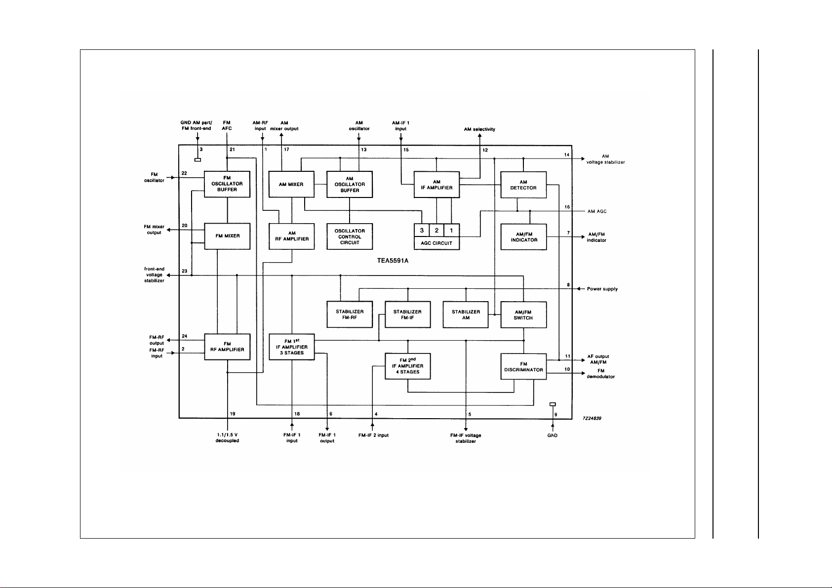
Fig.1 Block diagram.
This text is here in white to force landscape pages to be rotated correctly when browsing through the pdf in the Acrobat reader.This text is here in
_white to force landscape pages to be rotated correctly when browsing through the pdf in the Acrobat reader.This text is here inThis text is here in
white to force landscape pages to be rotated correctly when browsing through the pdf in the Acrobat reader. white to force landscape pages to be ...
February 1990 5
Philips Semiconductors Product specification
AM/FM radio receiver circuit TEA5591A
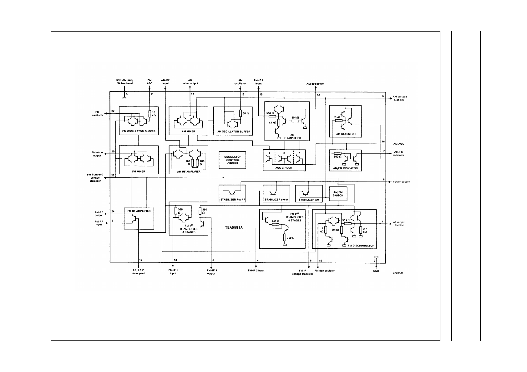
Fig.2 Equivalent circuit diagram.
 Loading...