


DATA SH EET
Product specification
File under Integrated Circuits, IC01
October 1990
INTEGRATED CIRCUITS
TEA5551T
1-chip AM radio

October 1990 2
Philips Semiconductors Product specification
1-chip AM radio TEA5551T
GENERAL DESCRIPTION
The TEA5551T is a 1-chip monolithic integrated radio circuit which is designed for use as a pocket receiver with
headphones in a supply voltage range (VS) of 1.8 V to 4.5 V.
The circuit consists of a complete AM part and dual AF amplifier with low quiescent current. The AF part has low radiation
(HF noise) and good overdrive performance. The dual AF amplifier makes the device suitable for operation in an AM/FM
stereo receiver with or without stereo cassette player. The IC has a 1-pin switch for AM or other applications.
Features
• Low voltage operation (V
S
= 1.8 V to 4.5 V)
• Low current consumption (I
tot
= 5 mA at VS = 3 V)
• All pins provided with ESD protection
AM part
• High sensitivity (Vi = 1.5 µV for Vo = 10 mV)
• Good IF suppression
• Good signal handling (V
i(max)
= 80 mV)
• Switch for AM or other applications
• Short waveband (> 40 MHz)
AF part
• A fixed integrated gain of 32 dB
• Few external components required
• Very low quiescent current
• Low HF radiation and good AF overdrive performance
• 0 to 20 kHz limited frequency response
• 25 mW per channel output power in 32 Ω

October 1990 3
Philips Semiconductors Product specification
1-chip AM radio TEA5551T
QUICK REFERENCE DATA (at T
amb
= 25 °C)
PACKAGE OUTLINE
16-lead mini-pack; plastic (SO16; SOT109A); SOT109-1; 1996 July 25.
PARAMETER CONDITIONS SYMBOL MIN. TYP. MAX. UNIT
Supply voltage V
S
1.8 3.0 4.5 V
Supply current I
5
+ I
10
− 6 − mA
AM part
m = 0.3
RF sensitivity
RF input voltage
V
o(AF)
= 10 mV V
i(RF)
− 1.5 −µV
S/N = 26 dB V
i(RF)
− 15 −µV
S/N = 50 dB V
i(RF)
− 10 − mV
AF output voltage V
i(RF)
= 1 mV V
o(AF)
− 80 − mV
Total harmonic distortion V
i(RF)
= 100 µV to 30 mV THD − 0.8 − %
Signal handling capability m = 0.8; THD = 10% V
i(RF)
− 80 − mV
AF part
both channels driven
Output power R
L
= 32 Ω; THD = 10%
at V
S
= 3.0 V P
o
− 25 − mW
at V
S
= 4.5 V P
o
− 60 − mW
Voltage gain P
o
= 10 mW G
v
− 32 − dB
Channel separation 1 kHz α−50 − dB
October 1990 4
Philips Semiconductors Product specification
1-chip AM radio TEA5551T
This text is here in white to force landscape pages to be rotated correctly when browsing through the pdf in the Acrobat reader.This text is here in
_white to force landscape pages to be rotated correctly when browsing through the pdf in the Acrobat reader.This text is here inThis text is here in
white to force landscape pages to be rotated correctly when browsing through the pdf in the Acrobat reader. white to force landscape pages to be ...
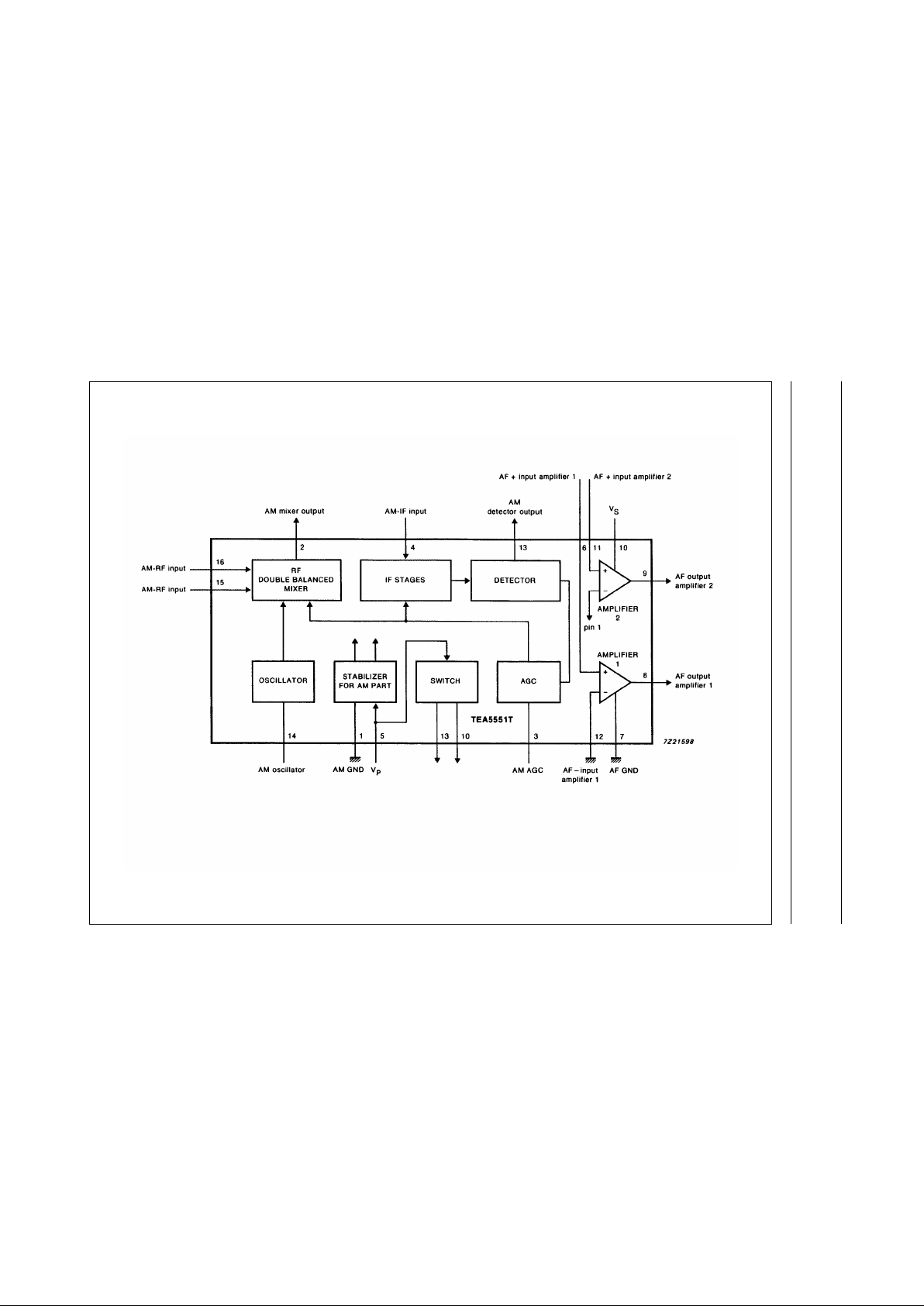
Fig.1 Block diagram.
October 1990 5
Philips Semiconductors Product specification
1-chip AM radio TEA5551T
PINNING
1 AM GND 9 AF output amplifier 2
2 AM mixer output 10 AF supply voltage (V
S
)
3 AM AGC 11 AF + input amplifier 2
4 AM-IF input 12 AF − input amplifier 1
5 AM supply voltage (V
P
) 13 AM detector output
6 AF + input amplifier 1 14 AM oscillator
7 AF GND 15 AM−RF input
8 AF output amplifier 1 16 AM−RF input
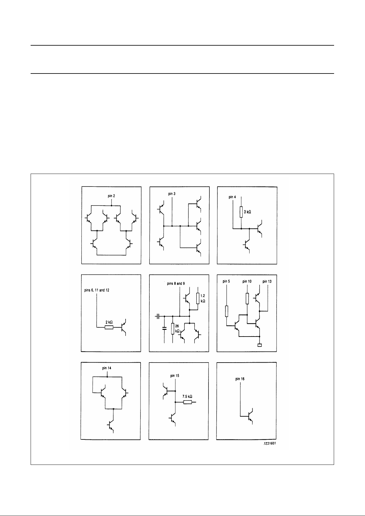
Fig.2 All pins provided with ESD protection diodes to substrate.
October 1990 6
Philips Semiconductors Product specification
1-chip AM radio TEA5551T
RATINGS
Limiting values in accordance with the Absolute Maximum System (IEC 134)
QUALITY
In accordance with UZW-BO/FQ-0601.
Operating life endurance verified 2000 hours at T
j
= 85 °C.
The product meets the 600 V ESD on all pins (HBM specification UZW-BO/FQ-A302).
THERMAL RESISTANCE
PARAMETER CONDITIONS SYMBOL MIN. MAX. UNIT
Supply voltage V
S
− 6V
Supply current (peak) I
M
− 150 mA
Crystal temperature T
c
− 150 °C
Short-circuit protection V
S
= 4.5 V t
sc
− 5s
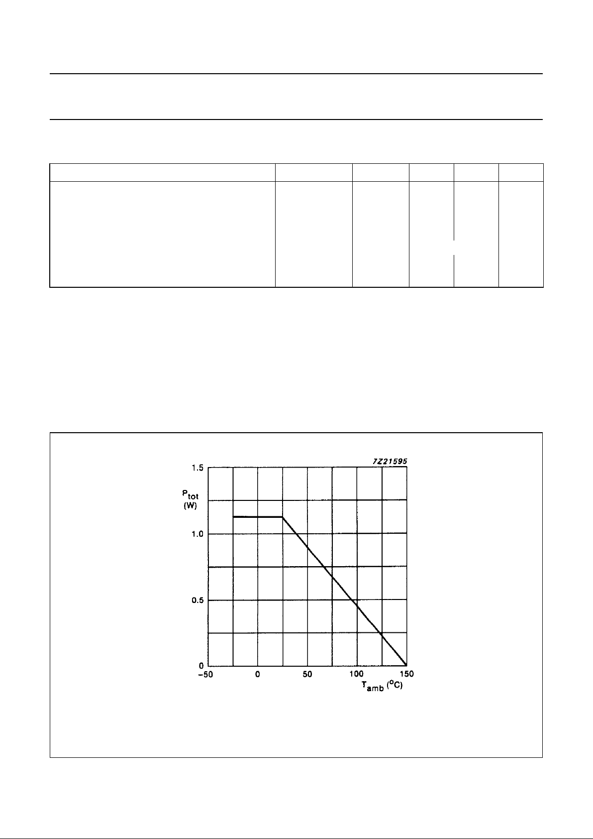
Total power dissipation P
tot
see Fig.3
Storage temperature range T
stg
−65 +150 °C
Operating ambient temperature range T
amb
−25 +60 °C
From junction to ambient R
th j-a
= 110 K/W
Fig.3 Power derating curve.
 Loading...