

Philips ReActiv 4.0 S, ReActiv PTE4000CR, ReActiv 4.0 U, PTE4000CU User Manual
ReActiv
Recumbent stepper
4.0 S
User manual
Please read this entire manual carefully
before operating your new recumbent
stepper and save it for future use.
PTE4000CS
Register your product and get support at
www.philips.com/welcome

Thank you for your recent purchase of the Philips physical rehabilitation
recumbent stepper 4.0 S.
Philips physical therapy and exercise solutions provide simple, reliable
products that oer the most relevant feedback to caregivers and
users to achieve best-in-class outcomes and empower individuals to
build condence in rebuilding and maintaining healthy lifestyles and
keep in touch with their communities.
Your new product has been manufactured by one of the world’s leading
medical product manufactures. It is backed by one of the most
comprehensive warranties in the industry. Through our dealers,
distributors and manufacturer’s representatives, we will do all we
can to provide many years of successful and prosperous ownership.
Your warranty and service needs will be addressed either through your
regional sales representative or our highly trained service technicians.
It is their responsibility to provide you with both the technical
knowledge and access to service personnel to make your ownership
experience more informed, and resolve any issues quickly.
Product registration
Register your product and get support at:
www.philips.com/welcome
This will ensure we have all your details quickly at hand in dealing with
any after sales support. For fastest support visit us and self service
solution at :
www.philips.com/support
Philips therapy solutions
Delivering better outcomes

Contents
Important safety instructions 4
Important electrical information
Important operation instructions 7
Features 8
Assembly instructions 9
Console operation 14
Using a heart rate transmitter 30
6
Maintenance 33

Important
safety
instructions
Attention
Read all instructions in this manual before using this device.
Danger
To reduce the risk of electric shock disconnect this device from the
electrical outlet prior to cleaning and/or service work.
Warning
• Before beginning exercise on this product, or any exercise program,
consult a physician. This is especially important for persons over the
age of 35 or persons with preexisting health conditions.
• There are obvious pinch points and other caution areas that can
cause harm.
• Children under the age of 13 should be supervised to ensure that they
do not play with the device.
• Keep hands away from all moving parts.
• Never drop or insert any object into any openings.
• Do not use outdoors.
4

• Do not operate this product on deeply padded, plush or shag
carpet. Damage to both carpet and product may result.
• Do not attempt to use this product for any purpose other than for
the purpose it is intended.
• Do not operate where aerosol spray products are being used or
where oxygen is being administered. Sparks from the motor may
ignite a highly gaseous environment.
• Never operate the product if it has a damaged cord or plug. If the
product is not working properly, call your dealer.
• Keep the cord away from heated surfaces.
• The hand pulse sensors are not medical devices. Various factors,
including the user’s movement, may aect the accuracy of heart rate
readings. The pulse sensors are intended only as an exercise aids in
determining heart rate trends in general.
• Heart rate monitoring systems may be inaccurate. Over exercising
may result in serious injury or death. If you feel faint stop exercising
immediately.
• Wear proper shoes. High heels, dress shoes, sandals or bare feet are
not suitable for use on your tness bike. Quality athletic shoes are
recommended to avoid leg fatigue.
• This appliance is not intended for use by persons (including children) with reduced physical, sensory or mental capabilities, or lack
of experience and knowledge, unless they have been given supervision or instruction concerning use of the appliance by a person
responsible for their safety.
• Maximum User Weight: 450 lbs.
• Save these instructions - think safety!
5

Important
electrical
information
Warning
• Never expose this product to rain or moisture. This product is not
designed for use outdoors, near a pool or spa, or in any other high
humidity environment. The operating temperature specication is 5
to 48 degrees Celsius (40 to 120 degrees Fahrenheit), and humidity
is 95% non-condensing (no water drops forming on surfaces).
6

Important
operation
instructions
• Never operate this product without reading and completely
understanding the results of any operational change you request
from the console.
• Understand that changes in resistance do not occur immediately.
Set your desired resistance level on the console and release the
adjustment key. The console will obey the command gradually.
• Use caution while participating in other activities while pedaling
on your product; such as watching television, reading, etc. These
distractions may cause you to lose balance which may result in
serious injury.
• Do not use excessive pressure on console control keys. They are
precision set to function properly with little nger pressure.
7
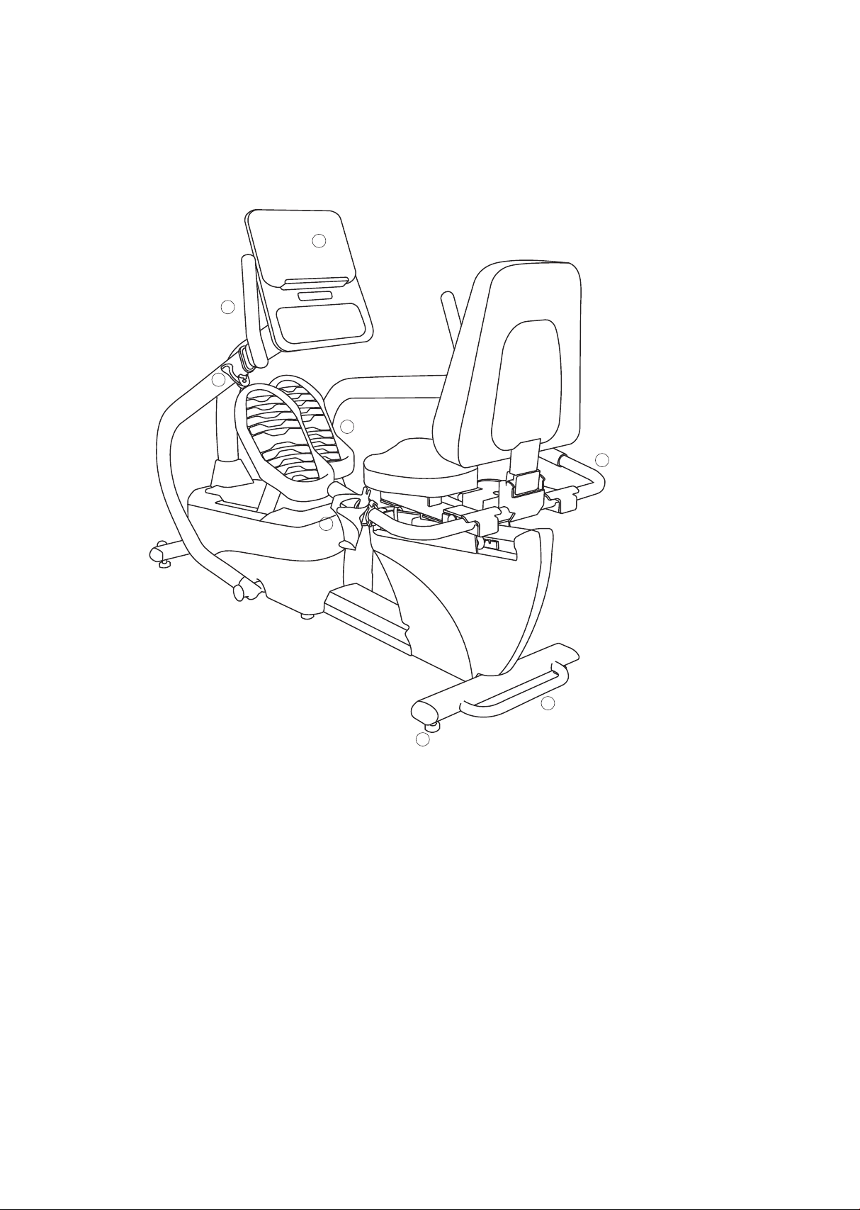
Features
1
2
3
4
8
7
5
4.0 S Recumbent stepper
6
Parts and adjustments
1. Console
2. Upper body handles
3. Quick release lever
4. Cushioned footplates
5. Lifting handle for transport
6. Leveling glides
7. Seat angle adjustment
8. Seat position adjustment
8

Assembly
instructions
Unpacking
• Cut the straps, then lift the box over the unit and unpack.
• Carefully remove all parts from the carton and inspect for any damage
or missing parts. If parts are damaged or missing, contact your dealer
immediately.
• Locate the hardware package. Remove the tools rst. Remove the
hardware for each step as needed to avoid confusion. The numbers in
the instructions that are in parenthesis (#) are the item number from
the assembly drawing for reference.
Tools included
• 5mm L allen wrench
• 8mm L allen wrench
• 12/14mm wrench
• 13/14mm wrench
• Phillips screwdriver
• Short phillips screwdriver
Parts included
• 1 main frame
• 2 foot pedals
• 1 seat cover
• 1 connecting arm
• 1 console mast
• 1 console mast cover
• 1 handle bar
• 4 end caps
• 2 transport wheels
• 1 seat
• 1 seat back frame
• 2 swing arms
• 1 console
• 1 hardware kit
• 1 drink bottle holder
• 1 power cord
9
Assembly
Read each step’s instructions and study the drawing carefully to become
familiar with all the parts and procedures before beginning each step.
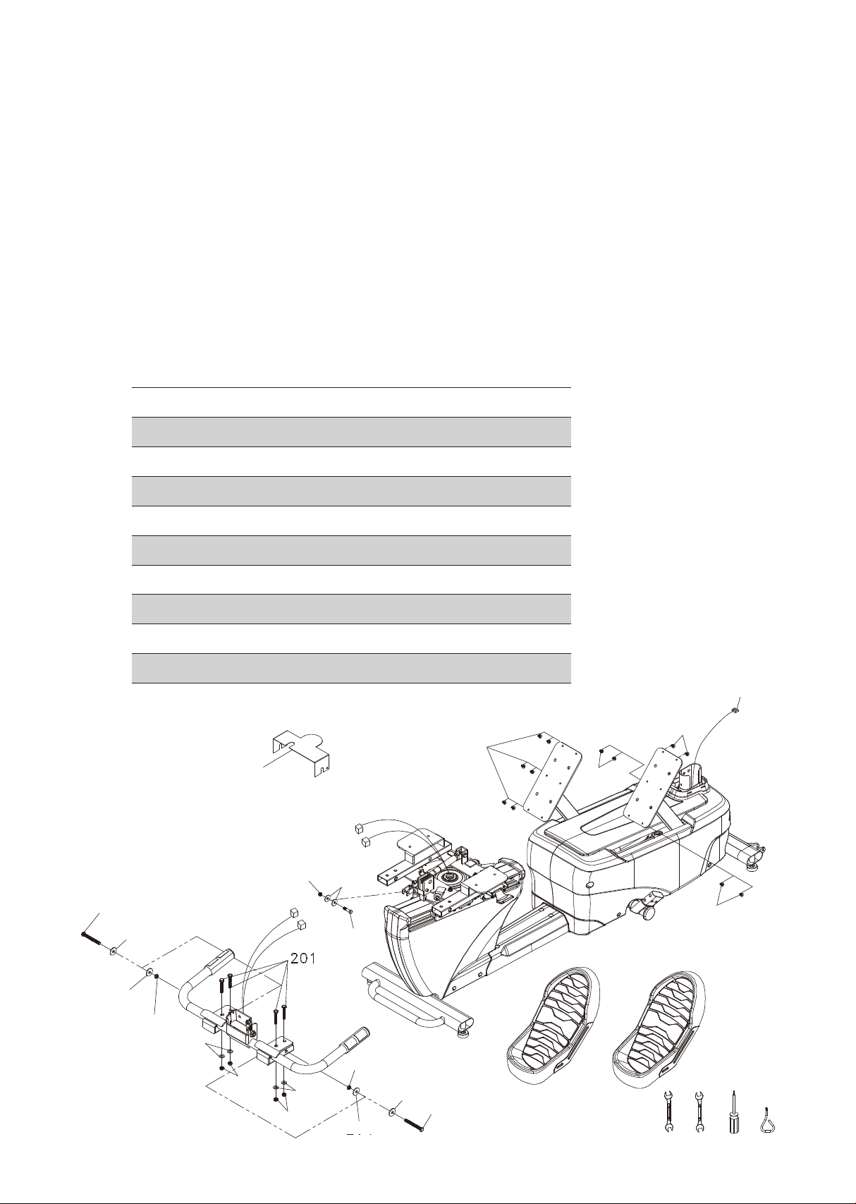
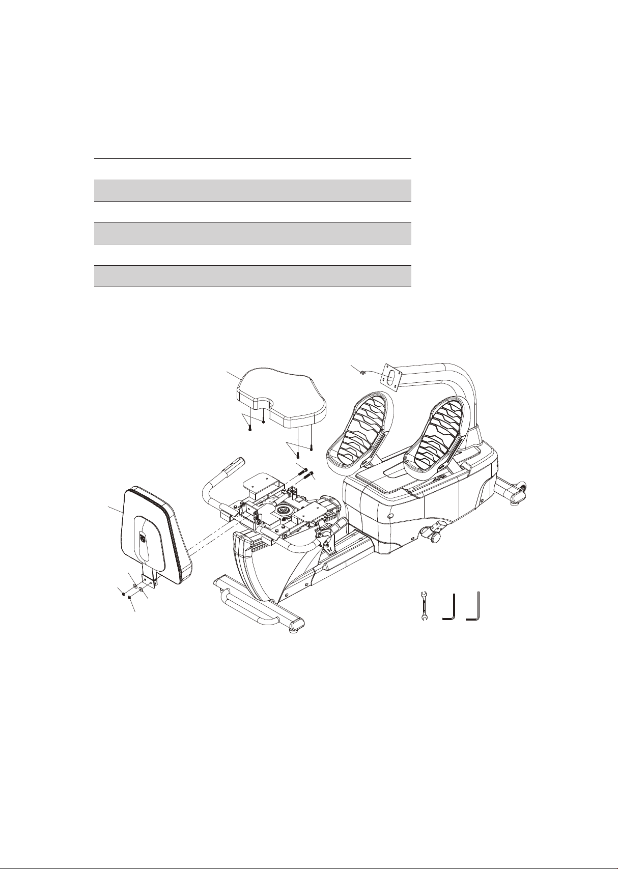
Step 1.
• Secure the pedals with phillips head screws (155).
• Install seat cover (45).
• Use hex head bolts (203) with at washers (204) and nyloc nuts (206)
and hex head bolts (201) and at washers (204) and nyloc nuts (206)
to secure handlebar on the seat assembly.
• Connect hand pulse cables; arrange cables taking care so they are not
crushed during seat adjustment.
Hardware for step 1
Part Type Description
203
201
202
155
204
205
206
161
Hex head bolt
Hex head bolt
Hex head bolt
Phillips head screw
Flat washer
Flat washer
Nyloc nut
Nyloc nut
45
3/8" x 3-1/4"
3/8" x 2"
5/16" x 1-1/4"
M5 x 12
3/8"
Ø8.5
3/8"
5/16"
155
Qty
2
4
1
12
8
2
6
1
Computer
cable
155
155
203
204
204
206
204
206
161
204
206
205
155
202
206
204
203
204
220 221 176 177
10
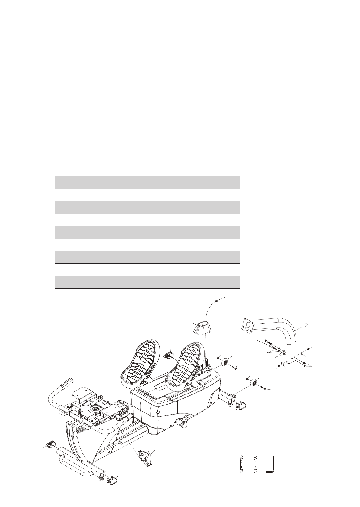
Step 2.
• Install transportation wheels (87) with button head bolts (209) and
nyloc nuts (161).
• Place the console mast (2) through the console mast cover (76) with
the correct orientation. Snake the console cables through the bottom
end of the console mast and out through the top.
• Insert the mast on the main frame and use hex head bolts (208) with
split washers (211), at washers (169) and nyloc nuts (206) to secure on
the side. Then use hex head bolts (207) and curved washers (210) to
secure at the front and back of the mast.
• Plug in the end caps (67) on oval stabilizer tubes.
• Install water bottle cage (111).
Hardware for step 2
Part Type Description
209
207
208
169
210
206
161
211
Button head bolt
Hex head bolt
Hex head bolt
Flat washer
Curved washer
Nyloc nut
Nyloc nut
Split washer
5/16" x 1-3/4"
M8 x 16
3/8" x 2-1/2"
3/8"
Ø8
3/8"
5/16"
Ø10
76
67
Qty
Computer
161
2
2
2
2
2
2
2
2
cable
87
209
208
161
211
87
169
207
207
210
206
210
67
67
209
67
111
173 174 217
11
Step 3.
• Put the seat cushion on the seat carriage and secure with hex head
bolts (145).
• Insert the seat back in the seat carriage and secure with hex head
bolts (212), at washers (172) and nyloc nuts (206).
Hardware for step 3
Part Type Description
145
172
206
212
Hex head bolt
Flat washer
Nyloc nut
Hex head bolt
35
M6
3/8"
3/8" x 7
3/8" x 1-3/4"
145
145
212
212
Qty
4
2
2
2
Computer
cable
36
206
172
172
206
221 217 219
12
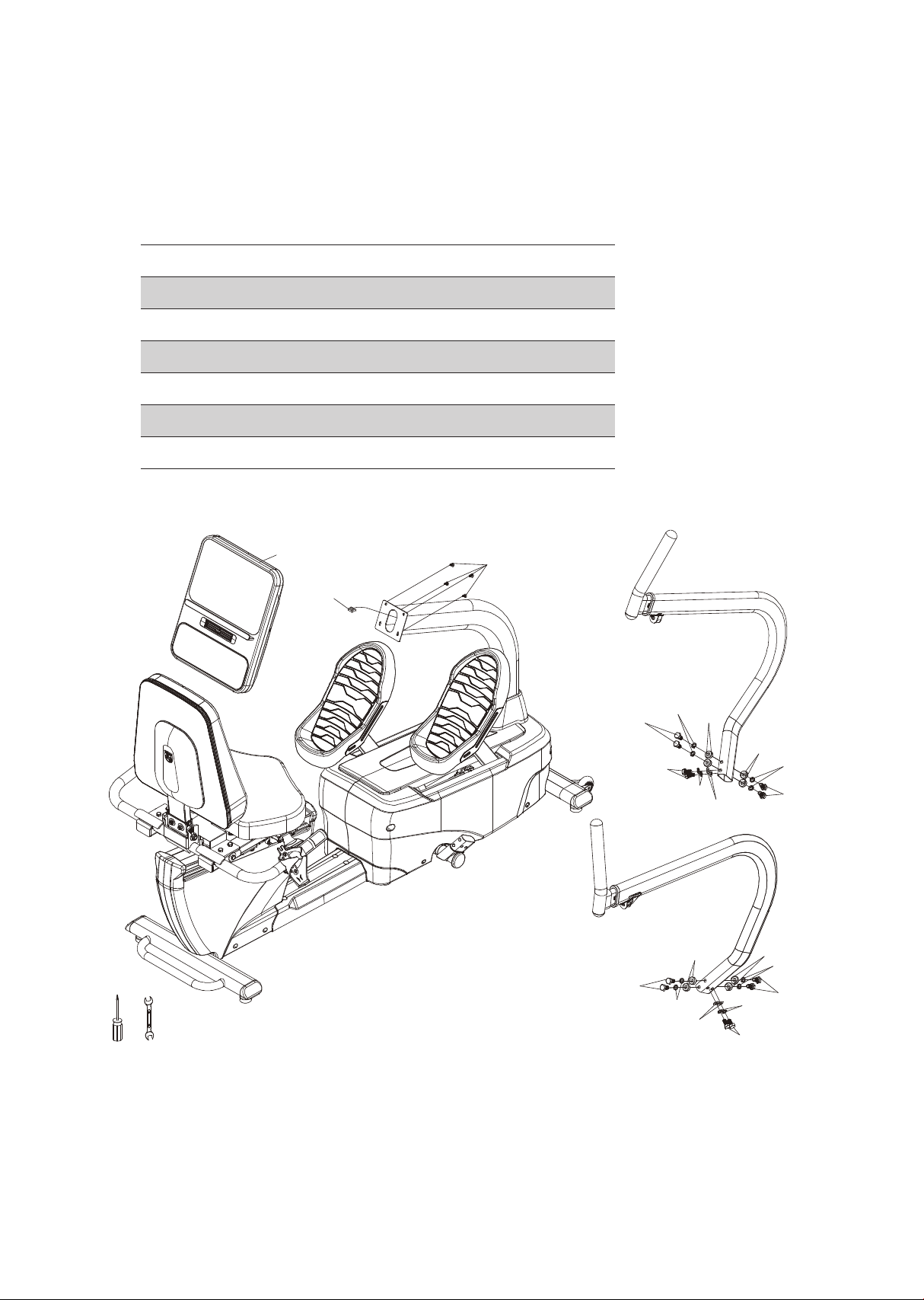
Step 4.
• Connect the cables from the mast to the console (27) and use phillips
head screws (155) to secure it.
• To install left and right swing arms use hex head bolts (213), at washers (214), split washers (216) and curved washers (215).
Hardware for step 4
Part Type Description
155
213
214
215
216
Phillips head screw
Button head bolt
Flat washer
Curved washer
Split washer
27
Computer
cable
M5 x 12
3/8" x 3/4"
3/8" x 19 x 1.5
10 x 21.3 x 7.8
Ø10
155
Qty
4
12
4
8
12
213
213
216
216
215
215
216
213
214
176 221
13
213
216
215
214
215
216
213
216
213
Console
operation
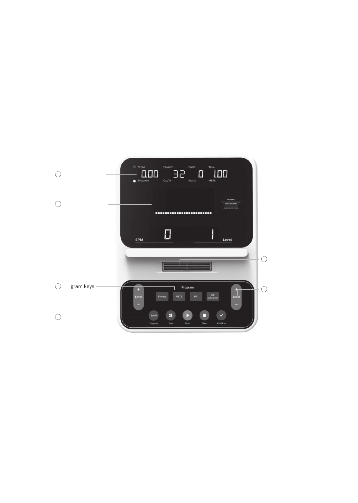
4.0 S console
1
Message window
2
Dot matrix window
5
Fan
3
Program keys
4
Function keys
6
Resistance level
or adjustment
up / down keys
Power on
The 4.0 S has a built in generator for power, but can be plugged into
an outlet for very low speed operation is required. When the 4.0 S is
pedaled, or the DC power cord is connected to the equipment, the
console will automatically power up.
The console will go to the start up display, also known as Idle mode.
The message window will be scrolling the start up message. You may
now begin to use the 4.0 S.
14

CSAFE feature
Your console is equipped with a CSAFE feature. The power (POWER)
port can be used for powering a remote controlled audio-visual system
by connecting a cable from the remote to the power port at the back of
the console. The Communication port (COMM) can be used to interact
with software applications.
Quick start
This is the quickest way to start a workout. After the console powers up
you just press the start key to begin. This will initiate the quick start
mode. In quick start, the time will count up from zero, all workout data
will start to accrue and the workload may be adjusted manually by
pressing the plus and minus keys. As you increase the workload more
rows will light indicating a harder workout. The stepper will get harder
to pedal as the rows increase.
There are 20 levels of resistance available for plenty of variety.
The rst 5 levels are very easy workloads, and the changes
between levels are set to a good progression for de-conditioned
users. Levels 6-10 are more challenging but the increases from
one level to the next remain small. Levels 11-15 start getting tough
as the levels jump more dramatically. Levels 16-20 are extremely
hard and are good for short interval peaks and higher
performance training.
15
 Loading...