


Philips Lighting North America Corporation
Philips Lighting Canada Ltd.
9140050346 February 2016
RCHF, RPHF, RWHF
Hazardous Location Fixtures
INSTALLATION INSTRUCTIONS
FOR MOUNTING ACCESSORIES
NOTE: Outlet box threads must be lubricated to
prevent galling. Lightly lubricate with Killark
“LUBT” lubricant or equivalent, for ease of future
maintenance.
NOTE: Refer to marking on fixture nameplate for
required supply wire temperature rating. Fixture
mount must be grounded. Connect the ground wire
to the green screw provided inside the mounts
(except wall bracket mount)
CEILING MOUNT (RCHF)
(See Figure 1)
Install ceiling mount on support surface by using
the (4) external mounting holes. Remove terminal
block from the mount and connect electrically as
described under Pendant Mount. Plug unused
conduit entries with closeup plugs provided.
PENDANT MOUNT (RPHF)
(See Figure 2)
Install pendant mount to conduit or use optional
(SEA) swivel elbow arm and secure with locking
set screw. Remove terminal block from the mount
by loosening the (2) mounting screws. Connect the
ground wire to the green screw. Connect supply
wires to the terminal block. Reinstall terminal block
and securely tighten it in place.
200 Franklin Square Drive
Somerset, NJ 08873, USA
Phone: 855-486-2216
www.philips.com/luminaires
281 Hillmount Road,
Markham ON, Canada L6C 2S3
Phone: 800-668-9008
www.philips.com/luminaires
Philips Lighting North America Corporation
Philips Lighting Canada Ltd.
9140050346 February 2016
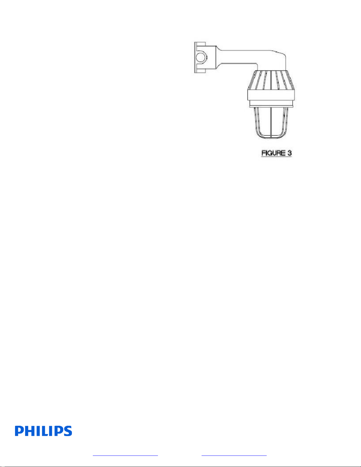
WALL BRACKET MOUNT (RWHF)
(See Figure 3)
Install wall bracket mount on support surface, using
the (2) external mounting holes. Unscrew and
remove inspection cap. Pull out Black (line), White
(common / neutral), and Green (ground) wires
through the inspection hole (wires will extend out
about 6 inches) and connect to supply wires using
wire nuts. Push the wires back in and replace the
cap. Plug unused conduit openings with closeup
plugs provided.
INSTALLATION INSTRUCTIONS
FOR LIGHTING FIXTURE
SAVE THESE INSTRUCTIONS
IMPORTANT:
(1): See fixture nameplate for specific hazardous
location suitability and specific supply wire
(minimum temperature rating).
(2): Verify the ground continuity in the electrical
system.
(3): Do not operate this fixture if the ambient
temperature exceeds the rating shown on the
nameplate.
WARNING: Turn OFF the supplying circuit
before beginning installation, or performing any
maintenance including relamping.
WARNING: Do not operate this fixture on an
ungrounded system.
NOTE: All installations must comply with
applicable local regulations and/or the National
Electrical Code.
200 Franklin Square Drive
Somerset, NJ 08873, USA
Phone: 855-486-2216
www.philips.com/luminaires
281 Hillmount Road,
Markham ON, Canada L6C 2S3
Phone: 800-668-9008
www.philips.com/luminaires

Philips Lighting North America Corporation
Philips Lighting Canada Ltd.
9140050346 February 2016
(1): Install fixture’s mounting accessory per
instructions mentioned elsewhere on this instruction
sheet.
(2): Loosen the locking screw “A”.
(3): Unscrew and remove globe support assembly
“B” from the fixture tank “C”. CAUTION: During
installation or maintenance, care should be taken to
avoid scratching, nicking, or chipping the glass
globe.
(4): Verify that the supply line voltage and fixture
nameplate voltage are compatible.
(5): Make sure that the external threads at the top of
the fixture tank are free of any dirt, metal chips, or
other foreign materials. Apply a thin coat of Killark
“LUBT” lubricant or equivalent, to the threads.
CAUTION: Take extreme care not to cross-thread
the fixture when installing into mounting accessory.
Install fixture by threading into mounting accessory;
the electrical contacts will automatically engage. Be
sure the fixture is tight.
(6): Tighten the set screw on the side of the
mounting accessory.
(7): Referring to the fixture nameplate, install the
proper size and type of lamp or use halogen lamp
and adaptor socket assembly iif supplied.
(8): Make sure the globe support threads are clean.
To prevent galling of threads, apply a thin coat of
Killark “LUBT” lubricant to the male threads.
Thread the globe support assembly into the fixture
tank and turn until there is no gap between the
flanges.
(9): Tighten the locking screw “A”
(10): To install guard “D”, loosen the four (4)
screws “E”, slip the guard over the screws and
rotate it to the locked position.
(11): Optional reflectors (SDR OR AR) may be
installed at this time.
(12): Optional exit frame (EFK) may be installed at
this time. Refer to instructions supplied with the
exit frame kit.
(13): Tighten the four (4) screws “E” firmly.
200 Franklin Square Drive
Somerset, NJ 08873, USA
Phone: 855-486-2216
www.philips.com/luminaires
281 Hillmount Road,
Markham ON, Canada L6C 2S3
Phone: 800-668-9008
www.philips.com/luminaires
 Loading...