

Philips pca9542 DATASHEETS
INTEGRATED CIRCUITS
PCA9542
2
2-channel I
C multiplexer and interrupt
controller
Product specification
Supersedes data of 1999 Oct 07
2000 Aug 30
Philips Semiconductors Product specification
PCA95422-channel I2C multiplexer and interrupt controller
FEA TURES
•1-of-2 bi-directional translating multiplexer
•Channel selection via I
2
C bus
•Operating supply voltage 2.5 to 3.6 V
•Operating temperature range –40°C to +85°C
•Power-up with all multiplexer channels deselected
•3 address pins, allowing up to 8 devices on the I
2
C bus
•Low on resistance
DESCRIPTION
The PCA9542 is a 1-of-2 bi-directional translating multiplexer,
controlled via the I
two SCx/SDx downstream pairs, or channels. Only one SCx/SDx
channel is selected at a time, determined by the contents of the
programmable control register . Two interrupt inputs, one for each of
the SCx/SDx downstream pair, are provided. One interrupt output,
which acts as an AND of the two interrupt inputs, is provided. All I/O
pins are 5 V tolerant.
The pass gates of the multiplexer are constructed such that the V
pin can be used to limit the maximum high voltage which will be
passed by the PCA9542. This allows the use of different bus
voltages on each SCx/SDx pair, so that 3.3 V parts can
communicate with 5 V parts without any additional protection.
External pull-up resistors can pull the bus up to the desired voltage
level for this channel.
2
C bus. The SCL/SDA upstream pair fans out to
DD
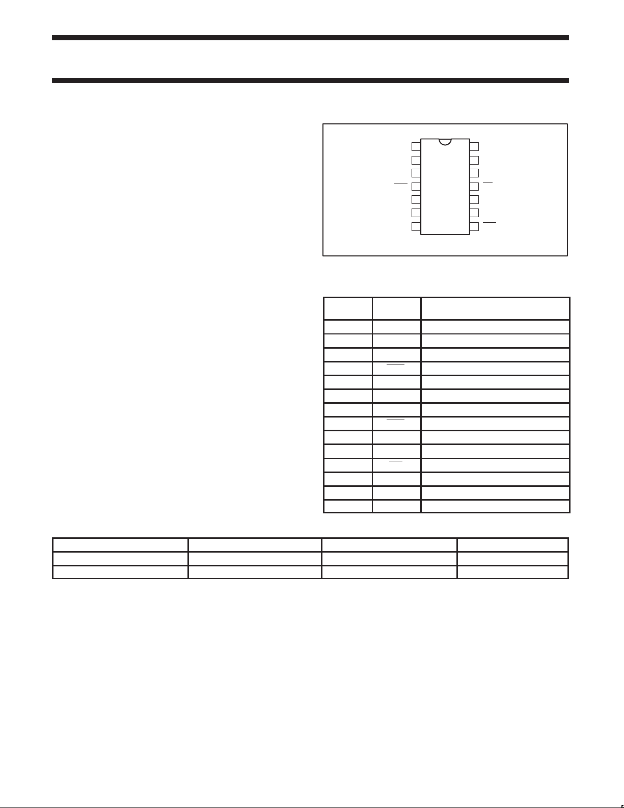
PIN CONFIGURATION
1
2
A1
3
A2
4
INT0
5
SD0
6
SC0
78
V
SS
PIN DESCRIPTION
PIN
NUMBER
1 A0 Address input 0
2 A1 Address input 1
3 A2 Address input 2
4 INT0 Interrupt input 0
5 SD0 Serial data 0
6 SC0 Serial clock 0
7 V
8 INT1 Interrupt input 1
9 SD1 Serial data 1
10 SC1 Serial clock 1
11 INT Interrupt output
12 SCL Serial clock line
13 SDA Serial data line
14 V
SYMBOL FUNCTION
Supply ground
SS
DD
Supply voltage
14A0
13
12
11
10
9
SW00475
V
DD
SDA
SCL
INT
SC1
SD1
INT1
ORDERING INFORMATION
PACKAGES TEMPERATURE RANGE ORDER CODE DRAWING NUMBER
14-Pin Plastic TSSOP –40°C to +85°C PCA9542PW SOT402-1
14-Pin Plastic SO –40°C to +85°C PCA9542 D SOT108-1
2000 Aug 30 853–2177 24454
2
Philips Semiconductors Product specification
PCA95422-channel I2C multiplexer and interrupt controller
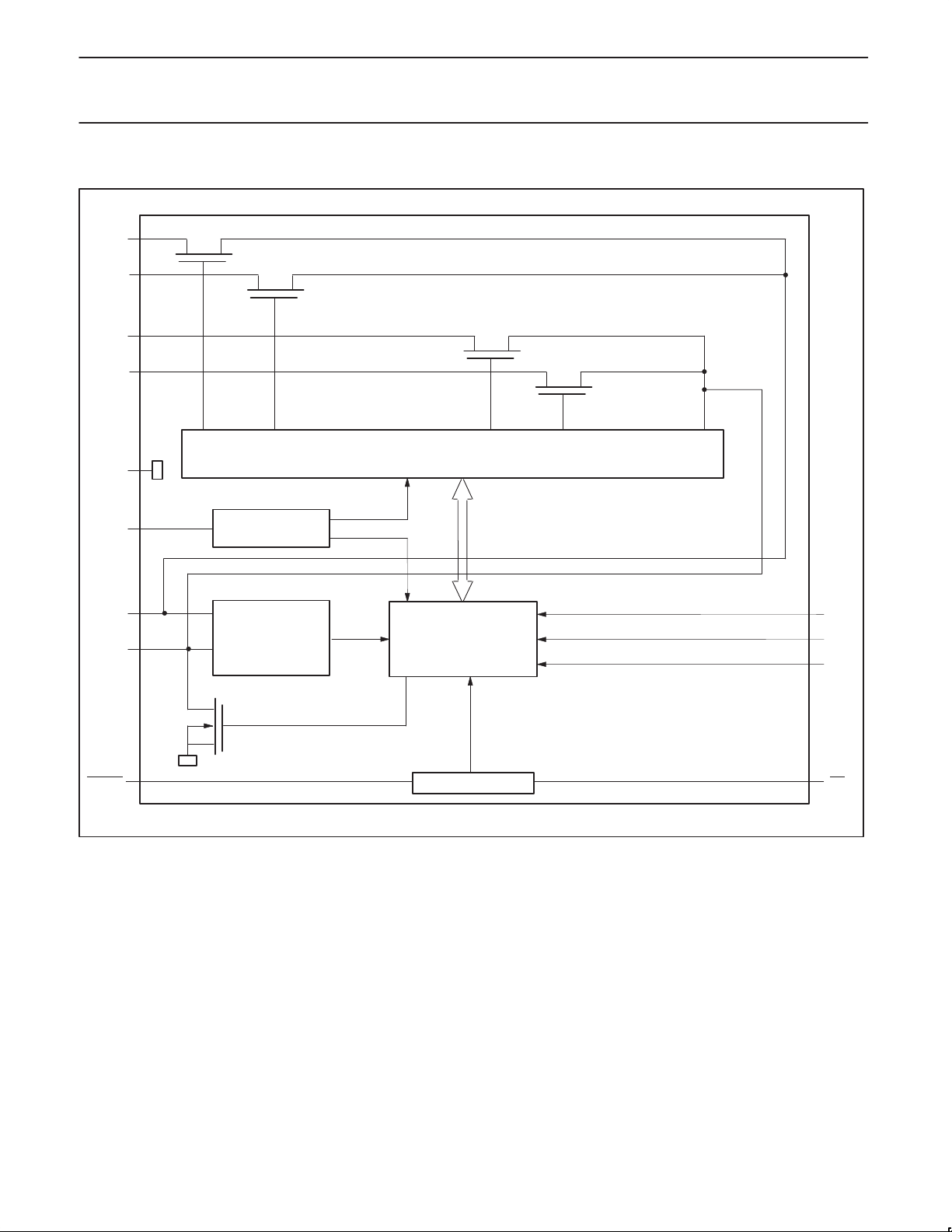
BLOCK DIAGRAM
SC0
SC1
SD0
SD1
V
SS
V
DD
SCL
SDA
INT[0–1] INT LOGIC INT
POWER-ON
RESET
INPUT
FILTER
2
I
C-BUS
CONTROL
SW00379
A0
A1
A2
2000 Aug 30
3
Philips Semiconductors Product specification
PCA95422-channel I2C multiplexer and interrupt controller
CHANNEL SELECTION
A SC0x/SD0x downstream pair, or channel, is selected by the
contents of the control register. This register is written after the
PCA9542 has been addressed. The 3 LSBs of the control byte are
used to determine which channel is to be selected. When a channel
is selected, the channel will become active after a stop condition has
been placed on the I
2
C bus. This ensures that all SCx/SDx lines will
be in a HIGH state when the channel is made active, so that no
false conditions are generated at the time of connection.
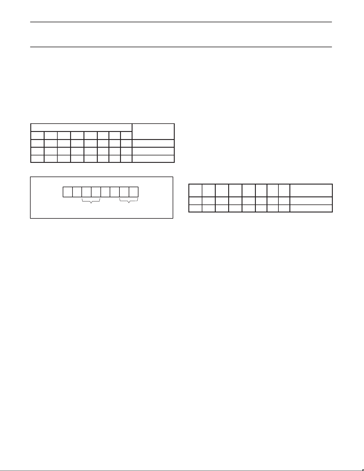
CONTROL BYTE
7 6 5 4 3 2 1 0
SELECTED
CHANNEL
X X X X X 0 X X none
X X X X X 1 0 0 0 (SC0/SD0)
X X X X X 1 0 1 1 (SC1/SD1)
CONTROL REGISTER
6 5 4 2 1 0 7 3
X INT1 INT0 B2 B1 B0
X
(read only) (read/write)
X
Channel select bitsInterrupt bits
SW00477
POWER-ON RESET
During power-up, the control register defaults to all zeroes causing
all the channels to be deselected.
INTERRUPT HANDLING
The PCA9542 provides 2 interrupt inputs, one for each channel and
one open drain interrupt output. When an interrupt is generated by any
device, it will be detected by the PCA9542 and the interrupt output
will be driven LOW. The channel need not be active for detection of
the interrupt. A bit is also set in the control byte.
Bits 4 – 5 of the control byte correspond to channels 0 – 1 of the
PCA9542, respectively. Therefore, if an interrupt is generated by any
device connected to channel 1, then bit 5 will be set in the control
register. Likewise, an interrupt on any device connected to channel 0
would cause bit 4 of the control register to be set. The master can
then address the PCA9542 and read the contents of the control byte
to determine which channel contains the device generating the
interrupt. The master can then reconfigure the PCA9542 to select this
channel, and locate the device generating the interrupt and clear it.
It should be noted that more than one device can be providing an
interrupt on a channel, so it is up to the master to ensure that all
devices on a channel are interrogated for an interrupt.
7
6 5 4 3 2 1 0
0 0 0 1 X X X X 0 (SC0/SD0)
0 0 1 0 X X X X 1 (SC1/SD1)
INTERRUPTING
CHANNEL
2000 Aug 30
4
 Loading...