

Philips N74F827D, N74F827N, N74F828N, N74F828D, N74F827DB Datasheet

INTEGRATED CIRCUITS
74F827
10-bit buffer/line driver, non-inverting
(3-State)
74F828
10-bit buffer/line driver, inverting
(3-State)
Product specification 1994 Dec 5
IC15 Data Handbook
Philips Semiconductors

Philips Semiconductors Product specification
74F827, 74F828Buffers
74F827 10-bit buffer/line driver, non-inverting (3-State)
74F828 10-bit buffer/line driver, inverting (3-State)
FEA TURES
•High impedance NPN base inputs for reduced loading (20µA in
High and Low states)
•I
is 20µA vs FAST family spec of 600µA and 1000µA for
IL
AMD 29827/29828 series
•Ideal where high speed, light bus loading and increased fan-in are
required
DESCRIPTION
The 74F827 and 74F828 10-Bit buffers provide high performance
bus interface buffering for wide data/address paths or buses
carrying parity. They have NOR Output Enables (OE
maximum control flexibility.
The 74F827 and 74F828 are functionally and pin compatible to AMD
AM29827 and AM29828. The 74F828 is an inverting version of
74F827.
•Controlled rise and fall times to minimize ground bounce
•Glitch free power-up in 3-State
•Flow through pinout architecture for microprocessor oriented
applications
TYPE
74F827 6.0ns 60mA
74F828 6.0ns 55mA
•Outputs sink 64mA
•74F827 available in SSOP type II package
ORDERING INFORMATION
PACKAGES
24-Pin Plastic DIP (300 mil) N74F827N, N74F828N SOT222-1
24-Pin Plastic SOL N74F827D, N74F828D SOT137-1
24-Pin Plastic SSOP Type II N74F827DB SOT340-1
INPUT AND OUTPUT LOADING AND FAN-OUT TABLE
PINS DESCRIPTION
D0-D9 Data inputs 1.0/0.033 20µA/20µA
OE0-OE1 Output enable inputs (active Low) 1.0/0.033 20µA/20µA
Q0-Q9 Data outputs (74F827) 1200/106.7 24mA/64mA
Q0-Q9 Data outputs ( 74F828) 1200/106.7 24mA/64mA
NOTES:
One (1.0) FAST Unit Load is defined as: 20µA in the High state and 0.6 mA in the Low state.
COMMERCIAL RANGE
VCC = 5V10%; TA = 0°C to +70°C
74F(U.L.)
HIGH/LOW
TYPICAL PROPAGATION
DELAY
DRAWING NUMBER
0, OE1) for
TYPICAL SUPPL Y
CURRENT
(TOTAL)
LOAD VALUE
HIGH/LOW
1994 Dec 05 853-0880 14382
2
Philips Semiconductors Product specification
74F827, 74F828Buffers
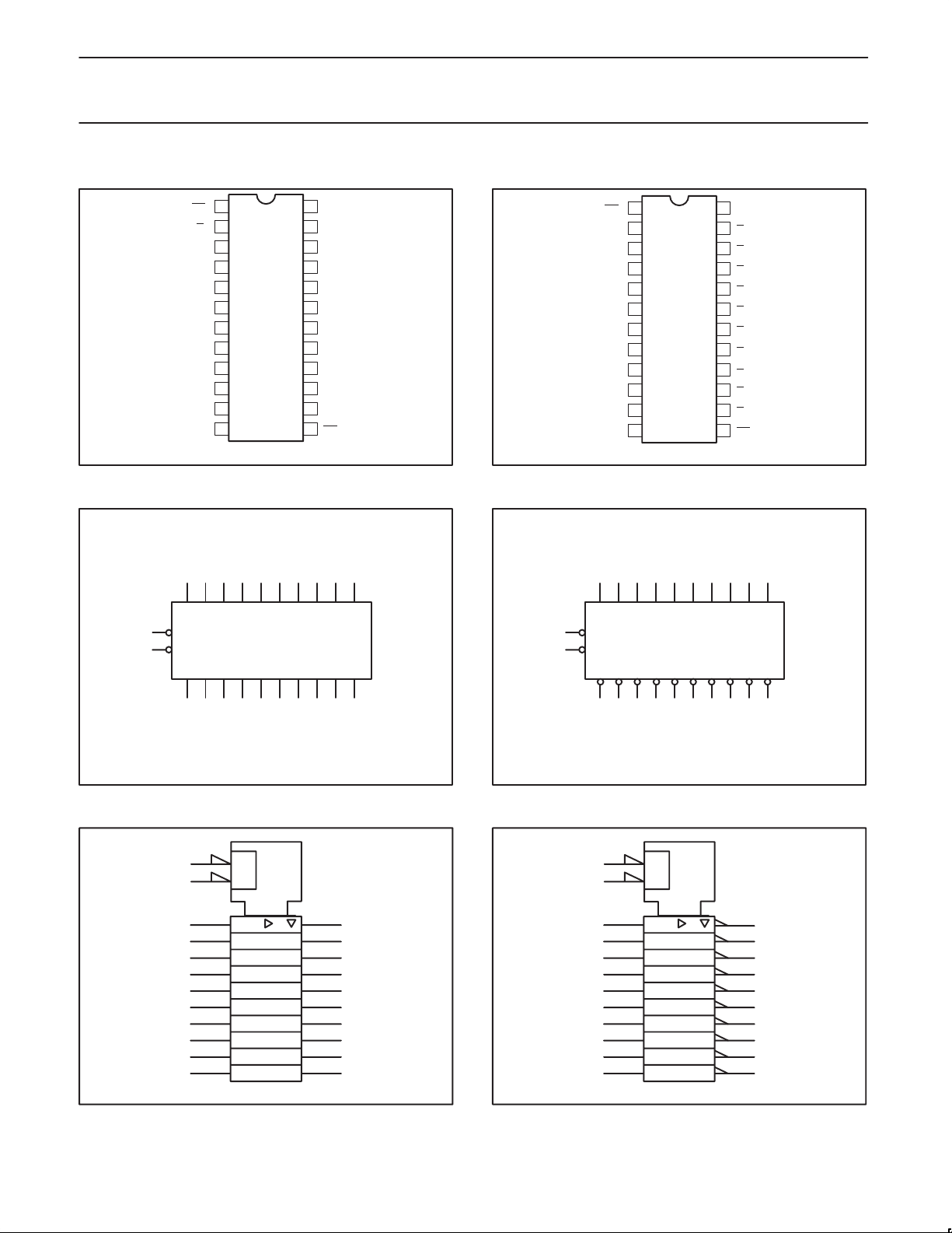
PIN CONFIGURATION - 74F827
1
0
OE
2
D
0
3
D1
4
D2
5
D3
6
D4
7
D5
8
D6
9
D7
10
D8
11
D9
12 13
GND
LOGIC SYMBOL - 74F827
234567891011
D0 D1 D2 D3 D4 D5 D6 D7 D8 D9
1
OE0
OE1
13
Q0 Q1 Q2 Q3 Q4 Q5 Q6 Q7 Q8 Q9
24
V
23
Q0
22
Q1
21
Q2
20
Q3
19
Q4
18
Q5
17
Q6
16
Q7
15
Q8
14
Q9
OE
SF00266
CC
PIN CONFIGURATION - 74F828
1
0
OE
2
D0
3
D1
4
D2
5
D3
6
D4
7
D5
8
D6
9
D7
10
D8
11
D9
12 13
1
GND
24
V
23
Q0
22
Q
21
Q
20
Q
19
Q
18
Q
17
Q6
16
Q
15
Q
14
Q
OE
SF00269
CC
1
2
3
4
5
7
8
9
1
LOGIC SYMBOL - 74F828
234567891011
D0 D1 D2 D3 D4 D5 D6 D7 D8 D9
1
OE0
OE1
13
Q0 Q1 Q2 Q3 Q4 Q5 Q6 Q7 Q8 Q9
23 22 21 20 19 18 17 16 15 14
VCC = Pin 24
GND = Pin 12
SF00267
LOGIC SYMBOL (IEEE/IEC) - 74F827
1
13
223
322
421
520
619
718
817
916
10 15
11 14
&
EN1
1
SF00268
23 22 21 20 19 18 17 16 15 14
VCC = Pin 24
GND = Pin 12
SF00270
LOGIC SYMBOL (IEEE/IEC) - 74F828
1
13
2
322
421
520
619
718
817
916
10 15
11 14
&
EN1
1
23
SF00271
1994 Dec 05
3

Philips Semiconductors Product specification
INPUTS
74F827, 74F828Buffers
LOGIC DIAGRAM 74F827
D0
2
1
OE0
13
OE1
VCC = Pin 24
GND = Pin 12
23
Q0
LOGIC DIAGRAM 74F828
D0
2
1
OE0
13
OE1
VCC = Pin 24
GND = Pin 12
23
0
Q
D1
Q1
D1
Q
3
22
3
22
1
D2
Q2
D2
Q2
D3
4
21
4
21
5
20
Q3
D3
5
20
Q3
D4
Q4
D4
Q4
D5
6
19
6
19
7
18
Q5
D5
7
18
Q5
D6
Q6
D6
Q6
D7
8
17
8
17
9
16
Q7
D7
9
16
Q7
D8
Q8
D8
Q8
D9
10
15
10
15
11
14
Q9
SF00272
D9
11
14
Q9
SF00280
FUNCTION TABLE
OUTPUTS
74F827 74F828
OPERATING MODE
OEn Dn Qn Qn
L L L H Transparent
L H H L Transparent
H X Z Z High impedance
H = High voltage level
L = Low voltage level
X = Don’t care
Z = High impedance “off” state
ABSOLUTE MAXIMUM RATINGS
Operation beyond the limits set forth in this table may impair the useful life of the device. Unless otherwise noted these limits are over the
operating free-air temperature range.
SYMBOL
V
CC
V
IN
I
IN
V
OUT
I
OUT
T
A
T
stg
Supply voltage –0.5 to +7.0 V
Input voltage –0.5 to +7.0 V
Input current –30 to +5 mA
Voltage applied to output in High output state –0.5 to +V
Current applied to output in Low output state 128 mA
Operating free-air temperature range 0 to + 70 °C
Storage temperature range –65 to + 150 °C
PARAMETER RATING UNIT
CC
V
1994 Dec 05
4
 Loading...