

Page 1

Philips M1165/66/67/75/76/77A
CMS Patient Monitoring System
and
Philips M1205A
V24 and V26 Patient Monitor
User’s Reference Manual
Volume 1
System Information
PHI
Part Number M1046-9220L
Printed 02/2003
Page 2

Notice
This document contains proprietary information which is protected by copyright. All Rights
Reserved. Reproduction, adaptation, or translation without prior written permission is
prohibited, except as allowed under the copyright laws.
Philips Medical Systems
Cardiac and Monitoring Systems
3000 Minuteman Road
Andover, MA 01810
Publication number
M1046-9220L
Warranty
The information contained in this document is subject to change without notice.
Philips Medical Systems makes no warranty of any kind with regard to this material,
including, but not limited to, the implied warranties or merchantability and fitness for a
particular purpose.
Philips Medical Systems shall not be liable for errors contained herein or for incidental or
consequential damages in connection with the furnishing, performance, or use of this
material.
© 2003 Philips Medizin Systeme Böblingen GmbH
All rights are reserved.
Reproduction in whole or in part is prohibited without the prior written consent of the
copyright holder.
Important
United States federal law restricts these devices to sale by or on the order of a physician.
ii
Page 3

The M1165/66/75/76A Systems comply with UL544, CSA 22.2-125, IEC 601-1, EN 60601-1, and
EN 60601-1-2 and carries Marking to Council Directive 93/42/EEC, European Medical
0366
Device Directive (MDD).
The M1167/77A Systems comply with UL2601-1, CSA 22.2 No. 601.1-M90, IEC 601-1,
EN 60601-1, and EN 60601-1-2 and carries Marking to Council Directive 93/42/EEC,
0366
European Medical Device Directive (MDD).
The M1205A Systems comply with UL2601, IEC 601-1, CSA C22.2 no. 601-1, EN60601-1, and
EN60601-1-2 and carries Marking to Council Directive 93/42/EEC, European Medical
0123
Device Directive (MDD).
iii
Page 4

Electromagnetic Interference
Anomalies due to electromagnetic interference are not unique to the M1165/66/67/75/76/77A
or the M1205A but are characteristic of patient monitors in use today. This performance is
due to the very sensitive high gain front end amplifiers used to display the physiological
signals. Among the many similarly performing patient monitors already in use by customers,
interference from electromagnetic sources is rarely a problem in actual use.
Avoiding Electromagnetic Interference
When electromagnetic interference (EMI) is encountered there are a number of actions that
can be taken to mitigate the problem.
• Eliminate the source. Possible sources of EMI can be turned off or moved away to
reduce their strength.
• Attenuate the coupling. If the coupling path is through the patient leads, the
interference may be reduced by moving and/or rearranging the leads. If the coupling is
through the power cord, plugging the patient monitor into a different circuit may help.
• Reduce the sensitivity of the system. In all of the EMC testing the patient monitor was
adjusted to maximum sensitivity. For the ECG amplifier the gain was four times what is
normally required. By reducing the gain of the system receiving the EMI, the
interference can often be eliminated.
• Add external attenuators. If EMI becomes an unusually difficult problem external
devices such as an isolation transformer or a transient suppressor may be of help. A
Philips Customer Engineer can be of help in determining the need for external devices.
Electromagnetic Compatibility (M1205A Only)
The electromagnetic compatibility (EMC) validation of the M1205A included testing
performed according to international standards for EMC with medical devices. See the
Manufacturer's Declaration for details.
EMC Testing. During the test program the M1205A was subjected to many EMC tests,
both international standard and Philips proprietary tests. There were no anomalies observed
during this testing.
iv
Page 5

Intended Use
Intended Use
Description
The Philips M1165/66/67/75/76/77A CMS Patient Monitoring System and the Philips M1205A
V24 and V26 Patient Monitors are network connectable bedside patient monitoring devices.
The Philips M1205A Models V24CT and V26CT may powered by either AC line power or by
battery power.
Purpose
The Philips M1165/66/67/75/76/77A CMS Patient Monitoring System and the Philips M1205A
V24 and V26 Patient Monitors measure and display multiple physiological parameters and
waves, and generate alarms and recordings. They exchange information with compatible
devices. The Philips M1165/66/67/75/76/77A CMS Patient Monitoring System and the Philips
M1205A V24 and V26 Patient Monitors are not therapeutic devices.
Environment
The Philips M1165/66/67/75/76/77A CMS Patient Monitoring System and the Philips M1205A
V24 and V26 Patient Monitors are intended to be used in a clinical environment by trained
healthcare professionals. They are not intended for home use.
They communicate with devices such as a central station through network interface ports and
a serial I/O port.
The Philips M1165/66/67/75/76/77A CMS Patient Monitoring System and the Philips M1205A
V24 and V26 Patient Monitors are prescription devices and will carry the following label,
“United States Federal law restricts this device to sale by or on the order of a physician.”
v
Page 6

Indications for Use
Indications for Use
Condition
The Philips M1165/66/67/75/76/77A CMS Patient Monitoring System and the Philips M1205A
V24 and V26 Patient Monitors are generally indicated when the clinician decides there is a
need to measure and display multiple physiological parameters and waves, to generate
alarms and recordings of adult, pediatric, or neonatal patients.
Part of Body or Type of Tissue with Which the Device Interacts
The Philips M1165/66/67/75/76/77A CMS Patient Monitoring System and the Philips M1205A
V24 and V26 Patient Monitors do not contact the body or tissue of the patient. Signals are
obtained from accessory electrode, transducer, and sensor devices.
Frequency of Use
The Philips M1165/66/67/75/76/77A CMS Patient Monitoring System and the Philips M1205A
V24 and V26 Patient Monitors are indicated for use when prescribed by a clinician.
Physiological Purpose
The Philips M1165/66/67/75/76/77A CMS Patient Monitoring System and the Philips M1205A
V24 and V26 Patient Monitors are indicated when the purpose is to gain information for
treatment, to assess adequacy of treatment, or to rule out causes of symptoms. The Philips
M1165/66/67/75/76/77A CMS Patient Monitoring System and the Philips M1205A V24 and V26
Patient Monitors are well suited for patient monitoring.
Patient Population
Adult, pediatric, and neonatal non-ambulatory patients.
vi
Page 7

Indications for Use
Prescription Versus Over-the-Counter
The Philips M1165/66/67/75/76/77A CMS Patient Monitoring System and the Philips M1205A
V24 and V26 Patient Monitors are prescription devices.
vii
Page 8

Indications for Use
Warnings, Cautions, and Notes
Warnings, cautions, and notes are used throughout this User's Manual to give you additional
information about the Philips M1165/66/67/75/76/77A CMS Patient Monitoring System and the
Philips M1205A V24 and V26 Patient Monitors. The warnings and cautions included in this
safety section refer to the equipment in general.
WarningWarning
A “warning” calls attention to the user of imminent hazard to people if proper
procedures are not followed.
• For continued safe use of this equipment, it is necessary that the listed instructions are
followed. Instructions in this manual in no way supersede established medical
procedures.
• Explosion Hazard- Do not use this equipment in the presence of flammable anesthetics.
• Alarms - Do not rely exclusively on the audible alarm system for patient monitoring.
Adjustment of alarm volume to a low level or off during patient monitoring may result
in patient jeopardy. Remember that the most reliable method of patient monitoring
combines close personal surveillance with correct operation of monitoring equipment.
• This equipment is only intended for use in healthcare facilities by trained healthcare
professionals.
• The product is not intended for outside hospital use such as a helicopters or
ambulances.
• This product is not intended for home use.
• To reduce the risk of electrical shock, do NOT remove any cover. Refer servicing to
qualified personnel.
• This equipment may interfere with ultrasound imaging equipment by causing
interference on the ultrasound display. Try to keep the instruments as far apart as
possible.
viii
Page 9

Indications for Use
• Exposure of electrical contacts or connections to saline or other liquids and gels is
dangerous. Electrical contacts and connections such as cable connectors, power
supplies, parameter module plug-in connections and rack connections must be kept
clean and dry. Thoroughly dry any electrical connections that become contaminated
with liquids. If additional decontamination is required please contact your biomedical
department or Philips Medical Systems Response Center.
• Although this equipment is shielded against Electromagnetic Interference (EMI), it is
recommended to avoid the use of electrically radiating devices in close proximity to this
equipment.
• Connecting the Philips monitoring network (SDN) cable when the product is powered on
is not supported. Error codes and Philips monitoring network (SDN) interface lock-up
may occur. Power cycling the product will recover the product. No permanent damage
will result. To prevent unintentional disruption in monitoring, be sure the SDN interface
cable is properly secured at both ends when connecting to the Philips monitoring
network (SDN).
• Do not connect a second rack by a cable when using a module rack docked to the back
of the V24CT or V26CT. Using a second rack connected by a cable may disrupt module
communication.
Caution
A “caution” calls attention to a condition or possible situation that could cause injury to the
user.
• Ventilation Requirements - Failure to meet ventilation requirements may cause
equipment failure and, in turn, jeopardize the functions of automated monitoring. Do not
locate equipment in an enclosed area which could restrict heat dissipation.
• Maintenance - Failure on the part of the responsible individual, hospital, or institution
employing the use of this equipment to implement a satisfactory maintenance schedule
may cause undue equipment failure and possible health hazards.
• Do not spray cleaning solutions directly onto the patient monitor. Moisture droplets may
enter the internal components and cause equipment malfunction or failure. Cleaning
solutions should be applied to a cloth and the cloth used to wipe the monitor clean. The
monitor should be turned off during cleaning.
ix
Page 10

Indications for Use
• Replacement Parts - It is highly recommended that only Philips Medical Systems
recommended parts and accessories be used with this equipment. Failure to do so may
result in the degradation of performance. Accessories and parts for individual modules
and components are listed at the back of the appropriate section in this manual.
Note—A note gives special instructions to highlight an operating procedure or practice. Notes
may precede or follow the applicable text.
At this time, Philips Medical Systems will make available on request, and in English only,
such circuit diagrams, component part lists, descriptions, calibration instructions, or other
information which will assist the user's appropriate qualified technical personnel to repair
those parts of the equipment which are classified by Philips Medical Systems to be
repairable. A list of Philips Sales and Support Offices is provided at the end of this manual.
Notice to the User
Although there may be products in your area that look similar to the Philips M1165/66/67/75/
76/77A CMS Patient Monitoring System and the Philips M1205A V24 and V26 Patient
Monitors, their functionality may not be the same. This User's Reference Manual is intended
to be used with the Philips M1165/66/67/75/76/77A CMS Patient Monitoring System, the
M1026A Anesthetic Gas Module and the Philips M1205A V24 and V26 Patient Monitors only.
This Manual is only applicable for Release C.1 versions of the CMS monitors and for Release
D.0 of the V24 and V26 monitors. A Release C.1 or Release D.0 monitor can be identified by:
a. the Release C.1 or D.0 label on the monitor, or
b. the suffix of the EPROM pack part number. To view this number, press
Monitor Setup
→ → .
Monitor Revision
Show SW Rev
The suffix of the EPROM pack part number on a Release C.1 CMS is E.
The Software Revision of a Release D.0 V24 or V26 monitor is M.00.03
x
Page 11

Responsibility of the Manufacturer
Responsibility of the Manufacturer
Philips Medical Systems only considers itself responsible for any effects on safety, reliability
and performance of the equipment if:
assembly operations, extensions, re-adjustments, modifications or repairs are carried out
by persons authorized by Philips, and
the electrical installation of the relevant room complies with national standards, and
the instrument is used in accordance with the instructions for use.
To ensure optimum usage, we recommend that Philips parts and accessories are used in
conjunction with the Philips M1165/66/67/75/76/77A CMS Patient Monitoring System, the
Philips M1026A Anesthetic Gas Module and the Philips M1205A V24 and V26 Patient Monitors,
wherever available. If non-Philips parts are used, Philips Medical Systems is not liable for any
damage that these parts may cause to the Philips equipment.
Manufacturer´s Address
For South America, North America and Canada:
Philips Medical Systems, Inc.
3000 Minuteman Road
Andover
MA 01810-1099
For all other countries:
Philips Medical Systems GmbH
Hewlett-Packard Str. 2
71034 Böblingen
Germany
xi
Page 12

Responsibility of the Manufacturer
xii
Page 13

Contents
This book is divided into th ree volumes.
This volume contains chapters 1 to 13 (see the following table of contents for more details):
1. The CMS and V24 and V26 Patient Monitors
2. Getting Started
3. Setting up your Monitor
4. Other Patients
5. Alarm Functions
6. Recording Functions
7. Admit/Discharge/End Case
8. Trends and Calculations
9. Neonat al Event Review
10. Data Transfer
11. Monitor Installation and Patient Safety
12. Battery Information (V24CT and V26CT only)
13. Maintenance
Volume 2 contai ns ch apters 12 to 22 (see the table of contents of Volume 2 for more details):
14. ECG and ECG/R espiration Mo dule Section
15. Noninvasive Blood Pressure Module S ection
16. SpO2/PLET H Module Section
17. Temperature Module Section
18. CO2 Module and Sidest ream Module Section
19. FIO2 Module Section (CMS only)
20. Pressure Module Section
21. Cardiac Output Module Section
22. VueLink Module Section
Volume 3 contains chapters 23 to 29 and appendices A to E (see the table of contents of Volume 3 for more
details):
23. SvO2 Module Section (CMS only))
24. tcpO2/tcpCO2 Module Section
25. Ventilator Interfaces and Respiratory Loops (CMS only)
26. Anesthetic Gas Module Section (Option #A05, #C03)
27. Blood Analysis
28. EEG Module Section (CMS only)
29. BIS“ Module Section
A. Summary of Formulas Used in Calculations
B. Analog Ou tput Se ction (CMS Only)
C. Calibrating the Pressure System
D. SpO2 Tr ansducer Information
E. Main Sales and Support Offic es
Contents-1
Page 14

Intended Use . . . . . . . . . . . . . . . . . . . . . . . . . . . . . . . . . . . . . . . . . . . . . . . . . . . . . . . . . . . . . . . . .1-v
Description. . . . . . . . . . . . . . . . . . . . . . . . . . . . . . . . . . . . . . . . . . . . . . . . . . . . . . . . . . . . . . .1-v
Purpose. . . . . . . . . . . . . . . . . . . . . . . . . . . . . . . . . . . . . . . . . . . . . . . . . . . . . . . . . . . . . . . . . .1-v
Environment. . . . . . . . . . . . . . . . . . . . . . . . . . . . . . . . . . . . . . . . . . . . . . . . . . . . . . . . . . . . . .1-v
Indications for Use . . . . . . . . . . . . . . . . . . . . . . . . . . . . . . . . . . . . . . . . . . . . . . . . . . . . . . . . . . . 1-vi
Condition . . . . . . . . . . . . . . . . . . . . . . . . . . . . . . . . . . . . . . . . . . . . . . . . . . . . . . . . . . . . . . . 1-vi
Part of Body or Type of Tissue with Which the Device Interacts. . . . . . . . . . . . . . . . . . . . 1-vi
Frequency of Use. . . . . . . . . . . . . . . . . . . . . . . . . . . . . . . . . . . . . . . . . . . . . . . . . . . . . . . . . 1-vi
Physiological Purpose . . . . . . . . . . . . . . . . . . . . . . . . . . . . . . . . . . . . . . . . . . . . . . . . . . . . . 1-vi
Patient Population . . . . . . . . . . . . . . . . . . . . . . . . . . . . . . . . . . . . . . . . . . . . . . . . . . . . . . . . 1-vi
Prescription Versus Over-the-Counter. . . . . . . . . . . . . . . . . . . . . . . . . . . . . . . . . . . . . . . . .1-vii
Responsibility of the Manufacturer. . . . . . . . . . . . . . . . . . . . . . . . . . . . . . . . . . . . . . . . . . . . . . . 1-xi
Manufacturer´s Address. . . . . . . . . . . . . . . . . . . . . . . . . . . . . . . . . . . . . . . . . . . . . . . . . . . . 1-xi
The CMS and V24 and V26 Patient Monitors 1-1
Introduction. . . . . . . . . . . . . . . . . . . . . . . . . . . . . . . . . . . . . . . . . . . . . . . . . . . . . . . . . . . . . . . . . .1-2
CMS Patient Monitoring System. . . . . . . . . . . . . . . . . . . . . . . . . . . . . . . . . . . . . . . . . . . . . . 1-2
V24 and V26 Patient Monitor . . . . . . . . . . . . . . . . . . . . . . . . . . . . . . . . . . . . . . . . . . . . . . . . 1-7
Control Panel . . . . . . . . . . . . . . . . . . . . . . . . . . . . . . . . . . . . . . . . . . . . . . . . . . . . . . . . . . . . . 1-8
The Handheld Keypad . . . . . . . . . . . . . . . . . . . . . . . . . . . . . . . . . . . . . . . . . . . . . . . . . . . . . 1-10
External Alarm Device. . . . . . . . . . . . . . . . . . . . . . . . . . . . . . . . . . . . . . . . . . . . . . . . . . . . .1-11
Hardkey Functions. . . . . . . . . . . . . . . . . . . . . . . . . . . . . . . . . . . . . . . . . . . . . . . . . . . . . . . .1-12
V26CT/V24CT Power Supply . . . . . . . . . . . . . . . . . . . . . . . . . . . . . . . . . . . . . . . . . . . . . . . . . . 1-14
Battery Power Supply . . . . . . . . . . . . . . . . . . . . . . . . . . . . . . . . . . . . . . . . . . . . . . . . . . . . .1-14
Parameter Modules . . . . . . . . . . . . . . . . . . . . . . . . . . . . . . . . . . . . . . . . . . . . . . . . . . . . . . . . . . .1-16
Symbols to Indicate Key Functions. . . . . . . . . . . . . . . . . . . . . . . . . . . . . . . . . . . . . . . . . . .1-17
Operating Levels. . . . . . . . . . . . . . . . . . . . . . . . . . . . . . . . . . . . . . . . . . . . . . . . . . . . . . . . . . . . .1-20
Main Screen . . . . . . . . . . . . . . . . . . . . . . . . . . . . . . . . . . . . . . . . . . . . . . . . . . . . . . . . . . . . . 1-21
Selection Window . . . . . . . . . . . . . . . . . . . . . . . . . . . . . . . . . . . . . . . . . . . . . . . . . . . . . . . .1-23
Task Window. . . . . . . . . . . . . . . . . . . . . . . . . . . . . . . . . . . . . . . . . . . . . . . . . . . . . . . . . . . . 1 -24
Getting into the Operating Levels . . . . . . . . . . . . . . . . . . . . . . . . . . . . . . . . . . . . . . . . . . . .1-25
Touch or Mouse/Trackball Operation. . . . . . . . . . . . . . . . . . . . . . . . . . . . . . . . . . . . . . . . . . . . .1-27
Main Screen . . . . . . . . . . . . . . . . . . . . . . . . . . . . . . . . . . . . . . . . . . . . . . . . . . . . . . . . . . . . . 1-28
Control Panel Task Window . . . . . . . . . . . . . . . . . . . . . . . . . . . . . . . . . . . . . . . . . . . . . . . .1-28
General Touch/Mouse/Trackball Operation (CMS only) . . . . . . . . . . . . . . . . . . . . . . . . . .1-29
Disabling Touch/Mouse/Trackball Operation . . . . . . . . . . . . . . . . . . . . . . . . . . . . . . . . . . .1-32
The CMS Computer Modules. . . . . . . . . . . . . . . . . . . . . . . . . . . . . . . . . . . . . . . . . . . . . . . . . . .1-33
M1046A Computer Module. . . . . . . . . . . . . . . . . . . . . . . . . . . . . . . . . . . . . . . . . . . . . . . . .1-33
M1046B Computer Module. . . . . . . . . . . . . . . . . . . . . . . . . . . . . . . . . . . . . . . . . . . . . . . . .1-34
Contents-2
Page 15

ECG Output and Defibrillator Marker Input . . . . . . . . . . . . . . . . . . . . . . . . . . . . . . . . . . . .1-34
The V24 and V26 Parameter Module Rack. . . . . . . . . . . . . . . . . . . . . . . . . . . . . . . . . . . . . . . . .1-35
Operating Rules to Remember. . . . . . . . . . . . . . . . . . . . . . . . . . . . . . . . . . . . . . . . . . . . . . . . . . .1-36
Performance Specifications of the Philips Displays . . . . . . . . . . . . . . . . . . . . . . . . . . . . . . . . . .1-37
M1095A Flatscreen Display. . . . . . . . . . . . . . . . . . . . . . . . . . . . . . . . . . . . . . . . . . . . . . . . .1-37
M1094A/B and M1092A CRT Display . . . . . . . . . . . . . . . . . . . . . . . . . . . . . . . . . . . . . . . .1-37
M1097A #A02 XGA Flatscreen Display . . . . . . . . . . . . . . . . . . . . . . . . . . . . . . . . . . . . . . .1-37
Using an ITE Display. . . . . . . . . . . . . . . . . . . . . . . . . . . . . . . . . . . . . . . . . . . . . . . . . . . . . . . . . .1-38
Safety . . . . . . . . . . . . . . . . . . . . . . . . . . . . . . . . . . . . . . . . . . . . . . . . . . . . . . . . . . . . . . . . . .1-3 8
EMC . . . . . . . . . . . . . . . . . . . . . . . . . . . . . . . . . . . . . . . . . . . . . . . . . . . . . . . . . . . . . . . . . . .1-39
Performance Requirements . . . . . . . . . . . . . . . . . . . . . . . . . . . . . . . . . . . . . . . . . . . . . . . . . .1-39
Getting Started 2-1
Setting up the Monitor (V24 and V26 only) . . . . . . . . . . . . . . . . . . . . . . . . . . . . . . . . . . . . . . . . .2-2
Setting up the Parameter Modules. . . . . . . . . . . . . . . . . . . . . . . . . . . . . . . . . . . . . . . . . . . . . . . . .2-5
Attaching the Patient . . . . . . . . . . . . . . . . . . . . . . . . . . . . . . . . . . . . . . . . . . . . . . . . . . . . . . . . . . .2-6
Adjusting Screen Contrast . . . . . . . . . . . . . . . . . . . . . . . . . . . . . . . . . . . . . . . . . . . . . . . . . . .2-7
Starting Monitoring. . . . . . . . . . . . . . . . . . . . . . . . . . . . . . . . . . . . . . . . . . . . . . . . . . . . . . . . .2-8
Screen Messages. . . . . . . . . . . . . . . . . . . . . . . . . . . . . . . . . . . . . . . . . . . . . . . . . . . . . . . . . . .2-8
Reserving a Channel. . . . . . . . . . . . . . . . . . . . . . . . . . . . . . . . . . . . . . . . . . . . . . . . . . . . . . . .2-9
Power Failure . . . . . . . . . . . . . . . . . . . . . . . . . . . . . . . . . . . . . . . . . . . . . . . . . . . . . . . . . . . .2-10
Patient Information Center . . . . . . . . . . . . . . . . . . . . . . . . . . . . . . . . . . . . . . . . . . . . . . . . . .2-10
Monitor Standby. . . . . . . . . . . . . . . . . . . . . . . . . . . . . . . . . . . . . . . . . . . . . . . . . . . . . . . . . .2-10
Setting up your Monitor 3-1
Changing Display Screens. . . . . . . . . . . . . . . . . . . . . . . . . . . . . . . . . . . . . . . . . . . . . . . . . . . . . . .3-2
Selecting a Screen . . . . . . . . . . . . . . . . . . . . . . . . . . . . . . . . . . . . . . . . . . . . . . . . . . . . . . . . . . . . .3-3
Procedure . . . . . . . . . . . . . . . . . . . . . . . . . . . . . . . . . . . . . . . . . . . . . . . . . . . . . . . . . . . . . . . .3-3
Freezing Waves (CMS only) . . . . . . . . . . . . . . . . . . . . . . . . . . . . . . . . . . . . . . . . . . . . . . . . . . . . .3-4
What you Can Configure. . . . . . . . . . . . . . . . . . . . . . . . . . . . . . . . . . . . . . . . . . . . . . . . . . . . . . . .3-5
Changes to the Configuration . . . . . . . . . . . . . . . . . . . . . . . . . . . . . . . . . . . . . . . . . . . . . . . . . . . .3-6
Making Changes to the Main Display . . . . . . . . . . . . . . . . . . . . . . . . . . . . . . . . . . . . . . . . . . . . . .3-7
Assigning Waves to Screen Channels . . . . . . . . . . . . . . . . . . . . . . . . . . . . . . . . . . . . . . . . . . . . . .3-8
Procedure . . . . . . . . . . . . . . . . . . . . . . . . . . . . . . . . . . . . . . . . . . . . . . . . . . . . . . . . . . . . . . . .3-9
Selecting a Screen . . . . . . . . . . . . . . . . . . . . . . . . . . . . . . . . . . . . . . . . . . . . . . . . . . . . . . . . . . . .3-10
Procedure . . . . . . . . . . . . . . . . . . . . . . . . . . . . . . . . . . . . . . . . . . . . . . . . . . . . . . . . . . . . . . .3-10
Selecting Screen Labels for Realtime Display Screens. . . . . . . . . . . . . . . . . . . . . . . . . . . . . . . .3-11
Procedure . . . . . . . . . . . . . . . . . . . . . . . . . . . . . . . . . . . . . . . . . . . . . . . . . . . . . . . . . . . . . . .3-11
Contents-3
Page 16

Selecting the Number of Waves . . . . . . . . . . . . . . . . . . . . . . . . . . . . . . . . . . . . . . . . . . . . . . . . .3-13
Procedure . . . . . . . . . . . . . . . . . . . . . . . . . . . . . . . . . . . . . . . . . . . . . . . . . . . . . . . . . . . . . . .3-13
Changing the Wave Overlap. . . . . . . . . . . . . . . . . . . . . . . . . . . . . . . . . . . . . . . . . . . . . . . . . . . .3-14
Procedure . . . . . . . . . . . . . . . . . . . . . . . . . . . . . . . . . . . . . . . . . . . . . . . . . . . . . . . . . . . . . . .3-14
Selecting Realtime Wave Speeds . . . . . . . . . . . . . . . . . . . . . . . . . . . . . . . . . . . . . . . . . . . . . . . .3-15
Procedure . . . . . . . . . . . . . . . . . . . . . . . . . . . . . . . . . . . . . . . . . . . . . . . . . . . . . . . . . . . . . . .3-15
Numerics On/Off . . . . . . . . . . . . . . . . . . . . . . . . . . . . . . . . . . . . . . . . . . . . . . . . . . . . . . . . .3-17
Additional Information . . . . . . . . . . . . . . . . . . . . . . . . . . . . . . . . . . . . . . . . . . . . . . . . . . . .3-19
Selecting an Application Window. . . . . . . . . . . . . . . . . . . . . . . . . . . . . . . . . . . . . . . . . . . . . . . .3-20
Procedure . . . . . . . . . . . . . . . . . . . . . . . . . . . . . . . . . . . . . . . . . . . . . . . . . . . . . . . . . . . . . . .3-20
Displaying Split Screen Trends. . . . . . . . . . . . . . . . . . . . . . . . . . . . . . . . . . . . . . . . . . . . . . . . . .3-22
oxyCRG Display. . . . . . . . . . . . . . . . . . . . . . . . . . . . . . . . . . . . . . . . . . . . . . . . . . . . . . . . . . . . .3-25
Notes on oxyCRG . . . . . . . . . . . . . . . . . . . . . . . . . . . . . . . . . . . . . . . . . . . . . . . . . . . . . . . . 3-26
CSA Display (CMS only) . . . . . . . . . . . . . . . . . . . . . . . . . . . . . . . . . . . . . . . . . . . . . . . . . . . . . .3-28
Notes on CSA. . . . . . . . . . . . . . . . . . . . . . . . . . . . . . . . . . . . . . . . . . . . . . . . . . . . . . . . . . . . 3-29
Wave Replace . . . . . . . . . . . . . . . . . . . . . . . . . . . . . . . . . . . . . . . . . . . . . . . . . . . . . . . . . . . . . . .3-30
Procedure . . . . . . . . . . . . . . . . . . . . . . . . . . . . . . . . . . . . . . . . . . . . . . . . . . . . . . . . . . . . . . .3-30
Trace Mode . . . . . . . . . . . . . . . . . . . . . . . . . . . . . . . . . . . . . . . . . . . . . . . . . . . . . . . . . . . . . . . . .3-31
Procedure . . . . . . . . . . . . . . . . . . . . . . . . . . . . . . . . . . . . . . . . . . . . . . . . . . . . . . . . . . . . . . .3-31
Configuring a Second Independent Display (CMS only) . . . . . . . . . . . . . . . . . . . . . . . . . . . . . . 3-32
Other Functions You Can Configure . . . . . . . . . . . . . . . . . . . . . . . . . . . . . . . . . . . . . . . . . . . . .3-33
Adjusting the Volume Control . . . . . . . . . . . . . . . . . . . . . . . . . . . . . . . . . . . . . . . . . . . . . . . . . .3-35
Procedure . . . . . . . . . . . . . . . . . . . . . . . . . . . . . . . . . . . . . . . . . . . . . . . . . . . . . . . . . . . . . . .3-35
Adjusting the Date and Time . . . . . . . . . . . . . . . . . . . . . . . . . . . . . . . . . . . . . . . . . . . . . . . . . . .3-37
Procedure . . . . . . . . . . . . . . . . . . . . . . . . . . . . . . . . . . . . . . . . . . . . . . . . . . . . . . . . . . . . . . .3-37
Selecting Waves for Central Recorders . . . . . . . . . . . . . . . . . . . . . . . . . . . . . . . . . . . . . . . . . . . 3-39
Configuring Module, Bedside and Central Recordings . . . . . . . . . . . . . . . . . . . . . . . . . . . . . . .3-40
Other Patients Controls . . . . . . . . . . . . . . . . . . . . . . . . . . . . . . . . . . . . . . . . . . . . . . . . . . . . . . . . 3-41
The Status Log Function. . . . . . . . . . . . . . . . . . . . . . . . . . . . . . . . . . . . . . . . . . . . . . . . . . . . . . .3-42
The Monitor Revision Function . . . . . . . . . . . . . . . . . . . . . . . . . . . . . . . . . . . . . . . . . . . . . . . . .3-43
Changing Default Settings and Patient Category . . . . . . . . . . . . . . . . . . . . . . . . . . . . . . . . . . . .3-44
Changing the Patient Category . . . . . . . . . . . . . . . . . . . . . . . . . . . . . . . . . . . . . . . . . . . . . . . . . .3-45
NBP . . . . . . . . . . . . . . . . . . . . . . . . . . . . . . . . . . . . . . . . . . . . . . . . . . . . . . . . . . . . . . . . . . .3-47
NBP Examples. . . . . . . . . . . . . . . . . . . . . . . . . . . . . . . . . . . . . . . . . . . . . . . . . . . . . . . . . . .3-47
ECG . . . . . . . . . . . . . . . . . . . . . . . . . . . . . . . . . . . . . . . . . . . . . . . . . . . . . . . . . . . . . . . . . . .3-49
Heart Rate (HR) / Pulse . . . . . . . . . . . . . . . . . . . . . . . . . . . . . . . . . . . . . . . . . . . . . . . . . . . . 3-51
RESP . . . . . . . . . . . . . . . . . . . . . . . . . . . . . . . . . . . . . . . . . . . . . . . . . . . . . . . . . . . . . . . . . .3-51
Pressure . . . . . . . . . . . . . . . . . . . . . . . . . . . . . . . . . . . . . . . . . . . . . . . . . . . . . . . . . . . . . . . . 3-51
SpO2. . . . . . . . . . . . . . . . . . . . . . . . . . . . . . . . . . . . . . . . . . . . . . . . . . . . . . . . . . . . . . . . . . . 3-51
Contents-4
Page 17

Changing the Configuration Set. . . . . . . . . . . . . . . . . . . . . . . . . . . . . . . . . . . . . . . . . . . . . . . . . .3-53
Procedure . . . . . . . . . . . . . . . . . . . . . . . . . . . . . . . . . . . . . . . . . . . . . . . . . . . . . . . . . . . . . . .3-54
Changing Operating Modes. . . . . . . . . . . . . . . . . . . . . . . . . . . . . . . . . . . . . . . . . . . . . . . . . . . . .3-55
Returning to Monitoring Mode. . . . . . . . . . . . . . . . . . . . . . . . . . . . . . . . . . . . . . . . . . . . . . .3-56
Procedure . . . . . . . . . . . . . . . . . . . . . . . . . . . . . . . . . . . . . . . . . . . . . . . . . . . . . . . . . . . . . . .3-57
The Test Signals Function . . . . . . . . . . . . . . . . . . . . . . . . . . . . . . . . . . . . . . . . . . . . . . . . . . . . . .3-58
Procedure . . . . . . . . . . . . . . . . . . . . . . . . . . . . . . . . . . . . . . . . . . . . . . . . . . . . . . . . . . . . . . .3-59
Analog Output (CMS only) . . . . . . . . . . . . . . . . . . . . . . . . . . . . . . . . . . . . . . . . . . . . . . . . .3-59
Parameter Settings Transfer. . . . . . . . . . . . . . . . . . . . . . . . . . . . . . . . . . . . . . . . . . . . . . . . . . . . .3-61
Parameter Settings Transfer Messages . . . . . . . . . . . . . . . . . . . . . . . . . . . . . . . . . . . . . . . . . . . .3-63
Other Patients 4-1
Overview . . . . . . . . . . . . . . . . . . . . . . . . . . . . . . . . . . . . . . . . . . . . . . . . . . . . . . . . . . . . . . . . . . . .4-2
Philips Patient Care System. . . . . . . . . . . . . . . . . . . . . . . . . . . . . . . . . . . . . . . . . . . . . . . . . . . . . .4-3
The Other Patients Selection Window . . . . . . . . . . . . . . . . . . . . . . . . . . . . . . . . . . . . . . . . . .4-3
Automatic Alarm Other Patients. . . . . . . . . . . . . . . . . . . . . . . . . . . . . . . . . . . . . . . . . . . . . . .4-4
Configuring the Other Patients Controls . . . . . . . . . . . . . . . . . . . . . . . . . . . . . . . . . . . . . . . .4-7
Using Philips Patient Care System with an Arrhythmia Computer. . . . . . . . . . . . . . . . . . . . . . . .4-8
Extended Overview (CMS only) . . . . . . . . . . . . . . . . . . . . . . . . . . . . . . . . . . . . . . . . . . . . . . . . .4-15
To View an Extended Other Patients Bed . . . . . . . . . . . . . . . . . . . . . . . . . . . . . . . . . . . . . .4-16
Alert Notification . . . . . . . . . . . . . . . . . . . . . . . . . . . . . . . . . . . . . . . . . . . . . . . . . . . . . . . . .4-17
Alarm Functions 5-1
Alarm Display . . . . . . . . . . . . . . . . . . . . . . . . . . . . . . . . . . . . . . . . . . . . . . . . . . . . . . . . . . . . . . . .5-2
Alarm Functions on the Control Panel . . . . . . . . . . . . . . . . . . . . . . . . . . . . . . . . . . . . . . . . . .5-2
Suspending Alarms. . . . . . . . . . . . . . . . . . . . . . . . . . . . . . . . . . . . . . . . . . . . . . . . . . . . . . . . .5-3
Silencing and Resetting Alarms . . . . . . . . . . . . . . . . . . . . . . . . . . . . . . . . . . . . . . . . . . . . . . .5-4
Alarm Priorities. . . . . . . . . . . . . . . . . . . . . . . . . . . . . . . . . . . . . . . . . . . . . . . . . . . . . . . . . . . .5-8
Individual Parameter Alarms . . . . . . . . . . . . . . . . . . . . . . . . . . . . . . . . . . . . . . . . . . . . . . . .5-10
When an Alarm Occurs. . . . . . . . . . . . . . . . . . . . . . . . . . . . . . . . . . . . . . . . . . . . . . . . . . . . .5-11
Alarm Setup . . . . . . . . . . . . . . . . . . . . . . . . . . . . . . . . . . . . . . . . . . . . . . . . . . . . . . . . . . . . . . . . .5-12
Getting into the Alarms Selection Window . . . . . . . . . . . . . . . . . . . . . . . . . . . . . . . . . . . . .5-12
Changing the Alarm Limits . . . . . . . . . . . . . . . . . . . . . . . . . . . . . . . . . . . . . . . . . . . . . . . . .5-13
Setting the Volume Control . . . . . . . . . . . . . . . . . . . . . . . . . . . . . . . . . . . . . . . . . . . . . . . . .5-14
The Nurse Call Relay . . . . . . . . . . . . . . . . . . . . . . . . . . . . . . . . . . . . . . . . . . . . . . . . . . . . . .5-15
Recording Functions 6-1
General Recorder Information. . . . . . . . . . . . . . . . . . . . . . . . . . . . . . . . . . . . . . . . . . . . . . . . . . . .6-2
Contents-5
Page 18

Recorders . . . . . . . . . . . . . . . . . . . . . . . . . . . . . . . . . . . . . . . . . . . . . . . . . . . . . . . . . . . . . . . .6-2
Controls and Indicators on the Plug-In Recorder. . . . . . . . . . . . . . . . . . . . . . . . . . . . . . . . . . 6-3
Controls and Indicators on the 4-Channel Recorder (CMS only) . . . . . . . . . . . . . . . . . . . . . 6-4
Recorder Capabilities. . . . . . . . . . . . . . . . . . . . . . . . . . . . . . . . . . . . . . . . . . . . . . . . . . . . . . .6-5
Types of Recordings . . . . . . . . . . . . . . . . . . . . . . . . . . . . . . . . . . . . . . . . . . . . . . . . . . . . . . . . . . . 6-7
Delayed Recording . . . . . . . . . . . . . . . . . . . . . . . . . . . . . . . . . . . . . . . . . . . . . . . . . . . . . . . . . . . .6-8
Definitions . . . . . . . . . . . . . . . . . . . . . . . . . . . . . . . . . . . . . . . . . . . . . . . . . . . . . . . . . . . . . . .6-8
Configuring Delayed Recordings. . . . . . . . . . . . . . . . . . . . . . . . . . . . . . . . . . . . . . . . . . . . . .6-9
Making Delayed Recordings . . . . . . . . . . . . . . . . . . . . . . . . . . . . . . . . . . . . . . . . . . . . . . . .6-11
Alarm Recording. . . . . . . . . . . . . . . . . . . . . . . . . . . . . . . . . . . . . . . . . . . . . . . . . . . . . . . . . . . . .6-12
Configuring Alarm Recordings . . . . . . . . . . . . . . . . . . . . . . . . . . . . . . . . . . . . . . . . . . . . . . 6-13
Alarm Recording Priorities . . . . . . . . . . . . . . . . . . . . . . . . . . . . . . . . . . . . . . . . . . . . . . . . . 6-14
Procedure Recordings . . . . . . . . . . . . . . . . . . . . . . . . . . . . . . . . . . . . . . . . . . . . . . . . . . . . . . . . .6-16
Configuring Procedure Recordings . . . . . . . . . . . . . . . . . . . . . . . . . . . . . . . . . . . . . . . . . . . 6-16
Making Procedure Recordings. . . . . . . . . . . . . . . . . . . . . . . . . . . . . . . . . . . . . . . . . . . . . . .6-17
ST Recordings . . . . . . . . . . . . . . . . . . . . . . . . . . . . . . . . . . . . . . . . . . . . . . . . . . . . . . . . . . .6-18
Realtime Wave Recordings . . . . . . . . . . . . . . . . . . . . . . . . . . . . . . . . . . . . . . . . . . . . . . . . . . . . .6-20
Definitions . . . . . . . . . . . . . . . . . . . . . . . . . . . . . . . . . . . . . . . . . . . . . . . . . . . . . . . . . . . . . .6-20
Configuring Preset Recording Modes . . . . . . . . . . . . . . . . . . . . . . . . . . . . . . . . . . . . . . . . .6-21
Making Preset Recordings. . . . . . . . . . . . . . . . . . . . . . . . . . . . . . . . . . . . . . . . . . . . . . . . . . 6 -22
Making Non-Preset Recordings. . . . . . . . . . . . . . . . . . . . . . . . . . . . . . . . . . . . . . . . . . . . . .6-22
Making Calibrated ECG Recordings. . . . . . . . . . . . . . . . . . . . . . . . . . . . . . . . . . . . . . . . . . 6-23
If the Recorder is Busy. . . . . . . . . . . . . . . . . . . . . . . . . . . . . . . . . . . . . . . . . . . . . . . . . . . . .6-23
Realtime Vital Signs / Blood Recordings . . . . . . . . . . . . . . . . . . . . . . . . . . . . . . . . . . . . . . . . . . 6 -25
Definitions . . . . . . . . . . . . . . . . . . . . . . . . . . . . . . . . . . . . . . . . . . . . . . . . . . . . . . . . . . . . . .6-25
Making a Single Vital Signs/Blood Recording . . . . . . . . . . . . . . . . . . . . . . . . . . . . . . . . . .6-27
Making Timed Sequences of Vital Signs/Blood Recordings. . . . . . . . . . . . . . . . . . . . . . . . 6-27
Trended Vital Signs Recordings . . . . . . . . . . . . . . . . . . . . . . . . . . . . . . . . . . . . . . . . . . . . . . . . .6-29
Header Information . . . . . . . . . . . . . . . . . . . . . . . . . . . . . . . . . . . . . . . . . . . . . . . . . . . . . . .6-29
Trend Data . . . . . . . . . . . . . . . . . . . . . . . . . . . . . . . . . . . . . . . . . . . . . . . . . . . . . . . . . . . . . .6-30
Making Trended Vital Signs Recordings. . . . . . . . . . . . . . . . . . . . . . . . . . . . . . . . . . . . . . .6-32
Neonatal Event Review Recordings . . . . . . . . . . . . . . . . . . . . . . . . . . . . . . . . . . . . . . . . . . . . . . 6-33
Tabular Neonatal Event Recordings . . . . . . . . . . . . . . . . . . . . . . . . . . . . . . . . . . . . . . . . . .6-33
oxyCRG Episode Recordings for Neonatal Events . . . . . . . . . . . . . . . . . . . . . . . . . . . . . . . 6-34
oxyCRG Recordings . . . . . . . . . . . . . . . . . . . . . . . . . . . . . . . . . . . . . . . . . . . . . . . . . . . . . . . . . .6-36
oxyCRG Alarm Recording. . . . . . . . . . . . . . . . . . . . . . . . . . . . . . . . . . . . . . . . . . . . . . . . . .6-38
Additional Information . . . . . . . . . . . . . . . . . . . . . . . . . . . . . . . . . . . . . . . . . . . . . . . . . . . . . . . .6-39
Annotations . . . . . . . . . . . . . . . . . . . . . . . . . . . . . . . . . . . . . . . . . . . . . . . . . . . . . . . . . . . . . 6-39
Changing the Recording Length . . . . . . . . . . . . . . . . . . . . . . . . . . . . . . . . . . . . . . . . . . . . .6-42
Contents-6
Page 19

Changing the Recorder Speed. . . . . . . . . . . . . . . . . . . . . . . . . . . . . . . . . . . . . . . . . . . . . . . .6-43
Changing the Recorder . . . . . . . . . . . . . . . . . . . . . . . . . . . . . . . . . . . . . . . . . . . . . . . . . . . . .6-43
Continuing a Timed Recording. . . . . . . . . . . . . . . . . . . . . . . . . . . . . . . . . . . . . . . . . . . . . . .6-43
Inserting a Calibration Signal. . . . . . . . . . . . . . . . . . . . . . . . . . . . . . . . . . . . . . . . . . . . . . . .6-44
Recording Layouts . . . . . . . . . . . . . . . . . . . . . . . . . . . . . . . . . . . . . . . . . . . . . . . . . . . . . . . .6-44
Recording Status Messages . . . . . . . . . . . . . . . . . . . . . . . . . . . . . . . . . . . . . . . . . . . . . . . . . . . . .6-46
Accessories and Ordering Information . . . . . . . . . . . . . . . . . . . . . . . . . . . . . . . . . . . . . . . . . . . .6-48
Loading Paper . . . . . . . . . . . . . . . . . . . . . . . . . . . . . . . . . . . . . . . . . . . . . . . . . . . . . . . . . . . . . . .6-49
Central Recorders . . . . . . . . . . . . . . . . . . . . . . . . . . . . . . . . . . . . . . . . . . . . . . . . . . . . . . . . .6-49
Loading Paper into the Plug-In Recorder . . . . . . . . . . . . . . . . . . . . . . . . . . . . . . . . . . . . . . .6-49
To Replace Paper in the Plug-In Recorder . . . . . . . . . . . . . . . . . . . . . . . . . . . . . . . . . . . . . .6-50
Cleaning the Print head in the Plug-In Recorder . . . . . . . . . . . . . . . . . . . . . . . . . . . . . . . . .6-52
Loading Paper into the Four Channel (M1117A) Recorder (CMS only). . . . . . . . . . . . . . .6-53
Cleaning the Roller on the Four Channel (M1117A) Recorder . . . . . . . . . . . . . . . . . . . . . .6-55
Admit/Discharge/End Case 7-1
Admitting a Patient . . . . . . . . . . . . . . . . . . . . . . . . . . . . . . . . . . . . . . . . . . . . . . . . . . . . . . . . . . . .7-2
Changing Patient Information. . . . . . . . . . . . . . . . . . . . . . . . . . . . . . . . . . . . . . . . . . . . . . . . .7-5
Discharging a Patient/Ending a Case . . . . . . . . . . . . . . . . . . . . . . . . . . . . . . . . . . . . . . . . . . .7-9
Trends and Calculations 8-1
Introduction to Trends & Calculations. . . . . . . . . . . . . . . . . . . . . . . . . . . . . . . . . . . . . . . . . . . . . .8-2
Viewing Patient Data . . . . . . . . . . . . . . . . . . . . . . . . . . . . . . . . . . . . . . . . . . . . . . . . . . . . . . . . . . .8-3
Trending Priority. . . . . . . . . . . . . . . . . . . . . . . . . . . . . . . . . . . . . . . . . . . . . . . . . . . . . . . . . . .8-5
Viewing Blood Measurements . . . . . . . . . . . . . . . . . . . . . . . . . . . . . . . . . . . . . . . . . . . . . . . .8-5
Viewing Vital Signs . . . . . . . . . . . . . . . . . . . . . . . . . . . . . . . . . . . . . . . . . . . . . . . . . . . . . . . .8-9
Selecting Parameters for Graph Trends . . . . . . . . . . . . . . . . . . . . . . . . . . . . . . . . . . . . . . . .8-12
Viewing Graph Trends . . . . . . . . . . . . . . . . . . . . . . . . . . . . . . . . . . . . . . . . . . . . . . . . . . . . .8-13
Performing and Reviewing Calculations. . . . . . . . . . . . . . . . . . . . . . . . . . . . . . . . . . . . . . . . . . .8-20
Performing Calculations. . . . . . . . . . . . . . . . . . . . . . . . . . . . . . . . . . . . . . . . . . . . . . . . . . . .8-21
Changing or Entering an Input Value. . . . . . . . . . . . . . . . . . . . . . . . . . . . . . . . . . . . . . . . . .8-25
Reviewing Calculations . . . . . . . . . . . . . . . . . . . . . . . . . . . . . . . . . . . . . . . . . . . . . . . . . . . .8-25
Printing Reports . . . . . . . . . . . . . . . . . . . . . . . . . . . . . . . . . . . . . . . . . . . . . . . . . . . . . . . . . . . . . .8-26
Printing Task Window Reports. . . . . . . . . . . . . . . . . . . . . . . . . . . . . . . . . . . . . . . . . . . . . . .8-26
Printing Scheduled Reports . . . . . . . . . . . . . . . . . . . . . . . . . . . . . . . . . . . . . . . . . . . . . . . . .8-26
What to Do If Your Report Does Not Print . . . . . . . . . . . . . . . . . . . . . . . . . . . . . . . . . . . . .8-30
Drug Calculator . . . . . . . . . . . . . . . . . . . . . . . . . . . . . . . . . . . . . . . . . . . . . . . . . . . . . . . . . . . . . .8-32
Contents-7
Page 20

Neonatal Event Review 9-1
Introduction to Neonatal Event Review. . . . . . . . . . . . . . . . . . . . . . . . . . . . . . . . . . . . . . . . . . . .9-2
Viewing Neonatal Events . . . . . . . . . . . . . . . . . . . . . . . . . . . . . . . . . . . . . . . . . . . . . . . . . . . . . . . 9-3
Manual Event Storage . . . . . . . . . . . . . . . . . . . . . . . . . . . . . . . . . . . . . . . . . . . . . . . . . . . . . .9-4
Graphical Details . . . . . . . . . . . . . . . . . . . . . . . . . . . . . . . . . . . . . . . . . . . . . . . . . . . . . . . . . .9-5
Operating Controls. . . . . . . . . . . . . . . . . . . . . . . . . . . . . . . . . . . . . . . . . . . . . . . . . . . . . . . .9-12
Viewing oxyCRG Episodes . . . . . . . . . . . . . . . . . . . . . . . . . . . . . . . . . . . . . . . . . . . . . . . . . . . .9-14
Operating Controls. . . . . . . . . . . . . . . . . . . . . . . . . . . . . . . . . . . . . . . . . . . . . . . . . . . . . . . .9-16
Adjusting Neonatal Event Review Settings . . . . . . . . . . . . . . . . . . . . . . . . . . . . . . . . . . . . . . . .9-18
Event Criteria. . . . . . . . . . . . . . . . . . . . . . . . . . . . . . . . . . . . . . . . . . . . . . . . . . . . . . . . . . . .9-19
Operating Controls. . . . . . . . . . . . . . . . . . . . . . . . . . . . . . . . . . . . . . . . . . . . . . . . . . . . . . . .9-21
Data Transfer 10-1
Data Transfer Module . . . . . . . . . . . . . . . . . . . . . . . . . . . . . . . . . . . . . . . . . . . . . . . . . . . . . . . . .10-2
Symbols to Indicate Key Functions. . . . . . . . . . . . . . . . . . . . . . . . . . . . . . . . . . . . . . . . . . .10-5
What is Transferred . . . . . . . . . . . . . . . . . . . . . . . . . . . . . . . . . . . . . . . . . . . . . . . . . . . . . . .10-5
Types of Transfer . . . . . . . . . . . . . . . . . . . . . . . . . . . . . . . . . . . . . . . . . . . . . . . . . . . . . . . . . . . .10-7
To Module . . . . . . . . . . . . . . . . . . . . . . . . . . . . . . . . . . . . . . . . . . . . . . . . . . . . . . . . . . . . . .10-7
To Monitor. . . . . . . . . . . . . . . . . . . . . . . . . . . . . . . . . . . . . . . . . . . . . . . . . . . . . . . . . . . . .10-10
Transferring Blood Analysis Data. . . . . . . . . . . . . . . . . . . . . . . . . . . . . . . . . . . . . . . . . . . 10-11
Combining Data . . . . . . . . . . . . . . . . . . . . . . . . . . . . . . . . . . . . . . . . . . . . . . . . . . . . . . . . . . . . 10-14
Time Conversion . . . . . . . . . . . . . . . . . . . . . . . . . . . . . . . . . . . . . . . . . . . . . . . . . . . . . . . . 10-14
Database Conversion . . . . . . . . . . . . . . . . . . . . . . . . . . . . . . . . . . . . . . . . . . . . . . . . . . . . .10-14
Vital Signs, Blood Review and Graphs. . . . . . . . . . . . . . . . . . . . . . . . . . . . . . . . . . . . . . . . . . .10-17
Time Stamp . . . . . . . . . . . . . . . . . . . . . . . . . . . . . . . . . . . . . . . . . . . . . . . . . . . . . . . . . . . . 10-17
Reports. . . . . . . . . . . . . . . . . . . . . . . . . . . . . . . . . . . . . . . . . . . . . . . . . . . . . . . . . . . . . . . .10-18
Troubleshooting . . . . . . . . . . . . . . . . . . . . . . . . . . . . . . . . . . . . . . . . . . . . . . . . . . . . . . . . . . . .10-19
Performance Specifications. . . . . . . . . . . . . . . . . . . . . . . . . . . . . . . . . . . . . . . . . . . . . . . . . . . .10-20
Data Transfer Module . . . . . . . . . . . . . . . . . . . . . . . . . . . . . . . . . . . . . . . . . . . . . . . . . . . .10-20
Monitor Installation and Patient Safety 11-1
Introduction. . . . . . . . . . . . . . . . . . . . . . . . . . . . . . . . . . . . . . . . . . . . . . . . . . . . . . . . . . . . . . . . .11-2
Installation Information. . . . . . . . . . . . . . . . . . . . . . . . . . . . . . . . . . . . . . . . . . . . . . . . . . . . . . . . 11-5
Power Source Requirements . . . . . . . . . . . . . . . . . . . . . . . . . . . . . . . . . . . . . . . . . . . . . . . .11-5
Grounding the System . . . . . . . . . . . . . . . . . . . . . . . . . . . . . . . . . . . . . . . . . . . . . . . . . . . . .11-5
Combining Equipment. . . . . . . . . . . . . . . . . . . . . . . . . . . . . . . . . . . . . . . . . . . . . . . . . . . . .11-8
Environment. . . . . . . . . . . . . . . . . . . . . . . . . . . . . . . . . . . . . . . . . . . . . . . . . . . . . . . . . . . . . 11-9
Condensation . . . . . . . . . . . . . . . . . . . . . . . . . . . . . . . . . . . . . . . . . . . . . . . . . . . . . . . . . . .11-11
Contents-8
Page 21

Explanation of Symbols used . . . . . . . . . . . . . . . . . . . . . . . . . . . . . . . . . . . . . . . . . . . . . . .11-12
Maintenance Checks . . . . . . . . . . . . . . . . . . . . . . . . . . . . . . . . . . . . . . . . . . . . . . . . . . . . . . . . .11-14
Patient Cables and Leads . . . . . . . . . . . . . . . . . . . . . . . . . . . . . . . . . . . . . . . . . . . . . . . . . .11-16
Controls and Connectors . . . . . . . . . . . . . . . . . . . . . . . . . . . . . . . . . . . . . . . . . . . . . . . . . . . . . .11-17
The Front Panel of the M1046A Computer Module. . . . . . . . . . . . . . . . . . . . . . . . . . . . . .11-17
The Front Panel of the M1046B Computer Module. . . . . . . . . . . . . . . . . . . . . . . . . . . . . .11-19
The Rear Panel of the M1046A/B Computer Modules . . . . . . . . . . . . . . . . . . . . . . . . . . .11-21
The Rear Panel of the Display Modules. . . . . . . . . . . . . . . . . . . . . . . . . . . . . . . . . . . . . . .11-23
The Rear Panel of the M1109A External Alarm Device . . . . . . . . . . . . . . . . . . . . . . . . . .11-29
The Rear Panel of the M1026A Anesthetic Gas Module . . . . . . . . . . . . . . . . . . . . . . . . . .11-30
Assembling the System. . . . . . . . . . . . . . . . . . . . . . . . . . . . . . . . . . . . . . . . . . . . . . . . . . . .11-31
The V24 and V26 Connectors . . . . . . . . . . . . . . . . . . . . . . . . . . . . . . . . . . . . . . . . . . . . . .11-34
Assembling the V24 and V26. . . . . . . . . . . . . . . . . . . . . . . . . . . . . . . . . . . . . . . . . . . . . . .11-36
Accessories and Ordering Information . . . . . . . . . . . . . . . . . . . . . . . . . . . . . . . . . . . . . . . . . . .11-37
Battery Information (V24CT and V26CT only) 12-1
AC and DC (Battery) Operation . . . . . . . . . . . . . . . . . . . . . . . . . . . . . . . . . . . . . . . . . . . . . . . . .12-2
Operating Instructions. . . . . . . . . . . . . . . . . . . . . . . . . . . . . . . . . . . . . . . . . . . . . . . . . . . . . .12-3
Battery Indicator and Messages. . . . . . . . . . . . . . . . . . . . . . . . . . . . . . . . . . . . . . . . . . . . . . . . . .12-6
External Battery Charger . . . . . . . . . . . . . . . . . . . . . . . . . . . . . . . . . . . . . . . . . . . . . . . . . . . . . . .12-8
Battery Care and Maintenance. . . . . . . . . . . . . . . . . . . . . . . . . . . . . . . . . . . . . . . . . . . . . . . . . . .12-9
Storage . . . . . . . . . . . . . . . . . . . . . . . . . . . . . . . . . . . . . . . . . . . . . . . . . . . . . . . . . . . . . . . . .12-9
Care and Handling . . . . . . . . . . . . . . . . . . . . . . . . . . . . . . . . . . . . . . . . . . . . . . . . . . . . . . .12-10
Accessories and Ordering Information . . . . . . . . . . . . . . . . . . . . . . . . . . . . . . . . . . . . . . . . . . .12-11
Maintenance 13-1
General cleaning of the System . . . . . . . . . . . . . . . . . . . . . . . . . . . . . . . . . . . . . . . . . . . . . . . . . .13-2
General Disinfecting of the System. . . . . . . . . . . . . . . . . . . . . . . . . . . . . . . . . . . . . . . . . . . . . . .13-4
Monitor Maintenance. . . . . . . . . . . . . . . . . . . . . . . . . . . . . . . . . . . . . . . . . . . . . . . . . . . . . . . . . .13-6
Inspect the System . . . . . . . . . . . . . . . . . . . . . . . . . . . . . . . . . . . . . . . . . . . . . . . . . . . . . . . .13-8
Perform a Start-up Sequence Test of the System . . . . . . . . . . . . . . . . . . . . . . . . . . . . . . . . .13-9
Verify the Integrity of the Display . . . . . . . . . . . . . . . . . . . . . . . . . . . . . . . . . . . . . . . . . . . .13-9
Perform a System Self-Test . . . . . . . . . . . . . . . . . . . . . . . . . . . . . . . . . . . . . . . . . . . . . . . .13-10
Performance Assurance Checks. . . . . . . . . . . . . . . . . . . . . . . . . . . . . . . . . . . . . . . . . . . . . . . . .13-11
Performance Assurance Test . . . . . . . . . . . . . . . . . . . . . . . . . . . . . . . . . . . . . . . . . . . . . . .13-11
Functional Testing Procedures . . . . . . . . . . . . . . . . . . . . . . . . . . . . . . . . . . . . . . . . . . . . . .13-13
Performing the ECG Module and ECG/RESP Self-Test . . . . . . . . . . . . . . . . . . . . . . . . . .13-15
Performing the Invasive . . . . . . . . . . . . . . . . . . . . . . . . . . . . . . . . . . . . . . . . . . . . . . . . . . .13-16
Contents-9
Page 22

Pressure Module Self-Test. . . . . . . . . . . . . . . . . . . . . . . . . . . . . . . . . . . . . . . . . . . . . . . . .13-16
Performing the NBP Module Self-Test . . . . . . . . . . . . . . . . . . . . . . . . . . . . . . . . . . . . . . .13-17
Performing the SpO2/Pleth Module Self-Test. . . . . . . . . . . . . . . . . . . . . . . . . . . . . . . . . .13-17
Performing the Cardiac Output Module Self-Test. . . . . . . . . . . . . . . . . . . . . . . . . . . . . . .13-17
Performing the tcpO2/tcpCO2 Module Self-Test . . . . . . . . . . . . . . . . . . . . . . . . . . . . . . .13-18
Performing the CO2 Module Self-Test . . . . . . . . . . . . . . . . . . . . . . . . . . . . . . . . . . . . . . .13-19
Performing the Temperature Module Self-Test. . . . . . . . . . . . . . . . . . . . . . . . . . . . . . . . .13-19
Performing the Blood Analysis Module Self-Test. . . . . . . . . . . . . . . . . . . . . . . . . . . . . . .13-20
Performing the Recorder Module Self-Test. . . . . . . . . . . . . . . . . . . . . . . . . . . . . . . . . . . .13-20
Performing the Data Management Database Self-Test . . . . . . . . . . . . . . . . . . . . . . . . . . .13-20
Tests for VueLink Module and Anesthetic Gas Module . . . . . . . . . . . . . . . . . . . . . . . . . .13-21
Contents-10
Page 23

1
The CMS and V24 and V26 Patient
Monitors
This chapter provides an overview of the CMS Patient
Monitoring Systems and V24 and V26 Patient Monitor
includes the following sections:
• Introduction . . . . . . . . . . . . . . . . . . . . . . . . . . . . . . . . . . . . . . 1-2
• Parameter Modules . . . . . . . . . . . . . . . . . . . . . . . . . . . . . . . 1-16
• V26CT/V24CT Power Supply . . . . . . . . . . . . . . . . . . . . . . . 1-14
• Operating Levels . . . . . . . . . . . . . . . . . . . . . . . . . . . . . . . . . 1-20
• Touch or Mouse/Trackball Operation. . . . . . . . . . . . . . . . 1-27
• The CMS Computer Modules . . . . . . . . . . . . . . . . . . . . . . . 1-33
• The V24 and V26 Parameter Module Rack. . . . . . . . . . . . 1-35
• Operating Rules to Remember. . . . . . . . . . . . . . . . . . . . . . 1-36
s. It
The CMS and V24 and V26 Patient Monitors 1-1
Page 24

The CMS and V24 and
Introduction
Introduction
V26 Patient Monitors
The Philips M1165/66/67/75/76/77 CMS Patient Monitoring System and
the Philips M1205A V24 and V26 Patient Monitors, hereafter referred to
as the “patient monitor”, are modular patient monitors with networking
and data management capabilities. All the systems can have modules
added or removed at a later time as needed, or you can interchange the
modules between systems in your unit.
Note—Some features explained in this manual are not available for both
the CMS and for the V24 and V26 Monitors. The respective sections are
marked throughout the manual with either “CMS only” or “V24 and V26
only”.
The following system types are available:
CMS Patient
Monitoring
System
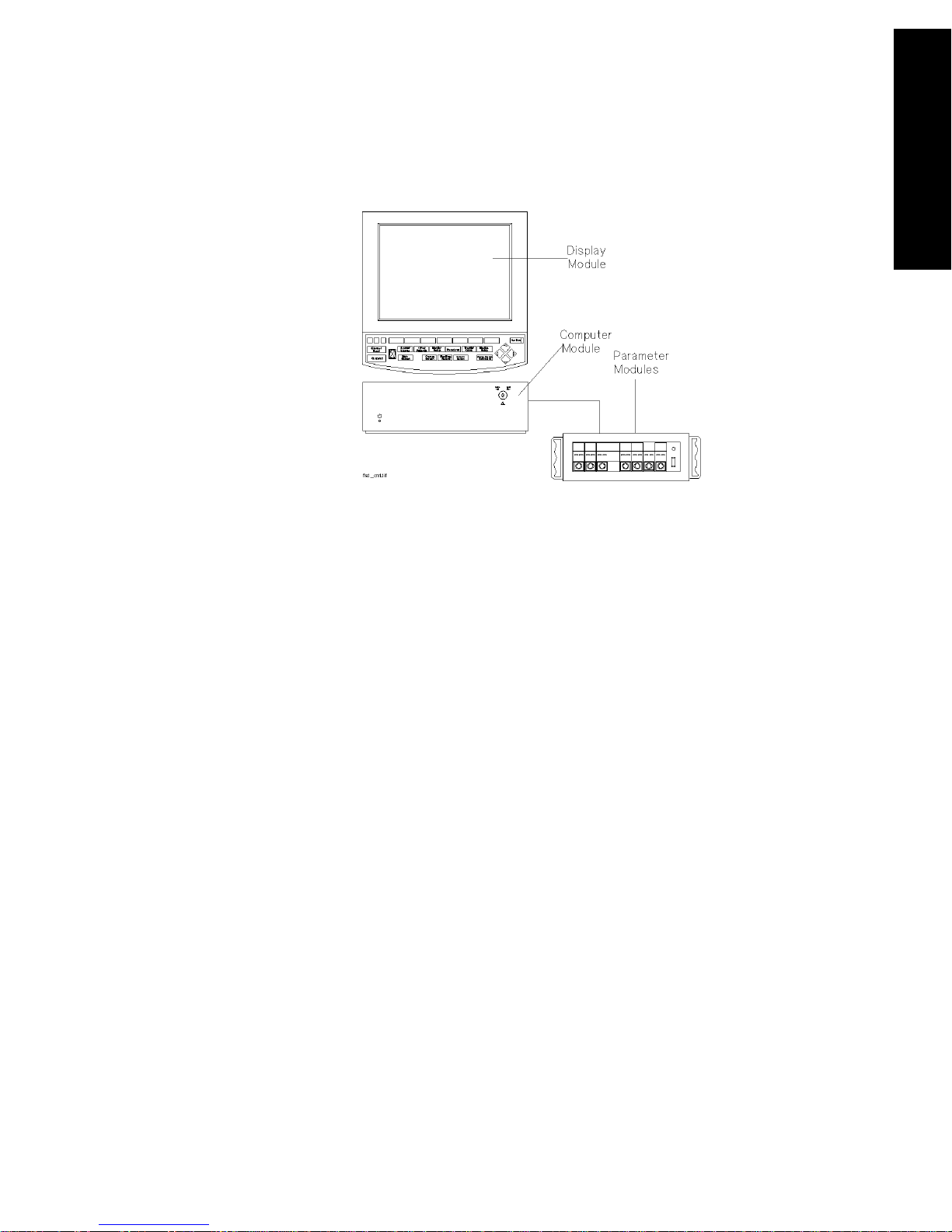
The CMS Patient Monitoring System is available as a choice of three
system types. Each system consists of three individual parts; a display
module, a computer module and parameter modules:
1. M1167/77A Color Flatscreen Display and Computer Module with
Satellite Module Rack
Note—This system is also available with an External Alarm Device and
an XGA compatible display controller to drive commercially available
ITE (Information Technology Equipment) displays (XGA Type).
2. M1165/75A Monochrome CRT Display and Computer Module with
Integral Module Rack
3. M1166/76A color CRT Display and Computer Module with Integral
Module Rack
1-2 The CMS and V24 and V26 Patient Monitors
Page 25
M1167/77A System
Display Module M1095A 10.4” Flatscreen Display
Introduction
The CMS and V24 and
V26 Patient Monitors
Computer Module M1046B Computer Module
Parameter Modules Satellite Rack
The CMS and V24 and V26 Patient Monitors 1-3
Page 26
The CMS and V24 and
Introduction
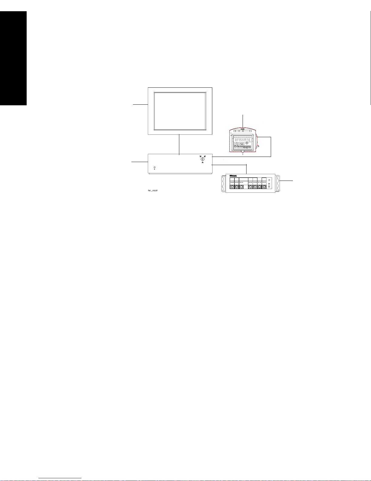
M1167/77A System with External Alarm Device
V26 Patient Monitors
XGA Display
External Alarm Device
Computer
Module
Parameter
Modules
Display Module ITE Display of choicea
b
Computer Module M1046B Computer Module
Parameter Modules Satellite Rack
a. Philips offers the M1167/77A #H05 and #H07 (XGA Touchscreen
display configuration).
b. A 15” flat touchscreen display is also available separately under the
order number M1097A # A02. A 17” C RT touchscreen displa y is als o
available separately under the order number M1098A
1-4 The CMS and V24 and V26 Patient Monitors
Page 27
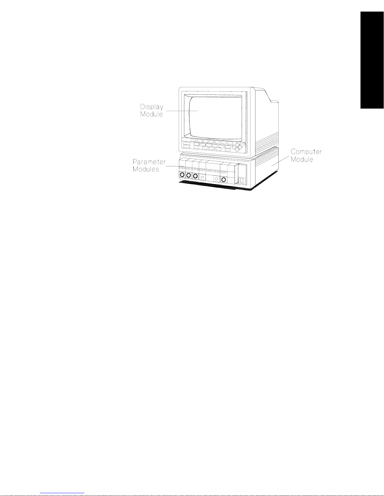
M1165/75A and M1166/76A System
Display Module M1094A/B/92A 14” CRT Display
Introduction
The CMS and V24 and
V26 Patient Monitors
Computer Module M1046A Computer Module
Parameter Modules Integral and/or Satellite Rack
Model Types All system types are also available as a choice of three different model
types:
Full Title Abbreviation
The Philips CMS Patient Monitoring System CMS
The Philips CMS Patient Monitoring System for
ACMS
Anesthesia Care
The Philips CMS Patient Monitoring System for
NCMS
Neonatal Care
Note—In this manual, the system will be referred to as the CMS, the ACMS
and the NCMS.
The CMS and V24 and V26 Patient Monitors 1-5
Page 28
Introduction
The CMS and V24 and
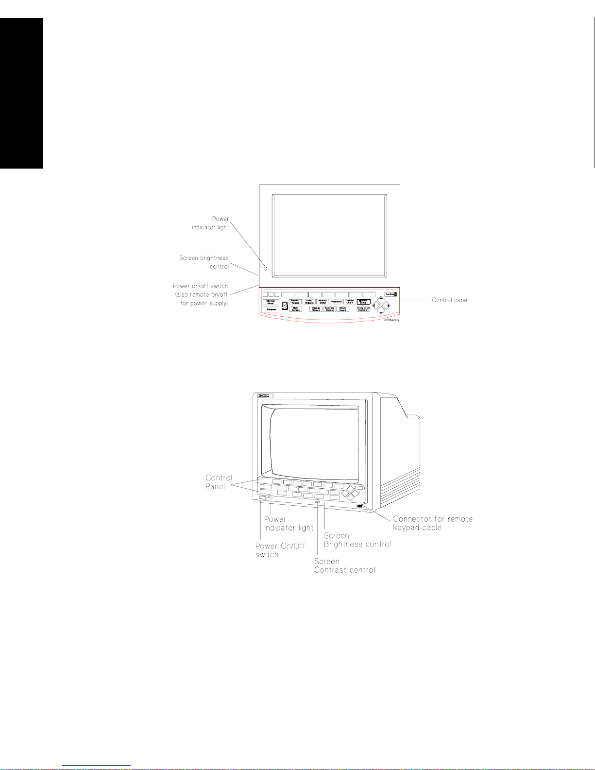
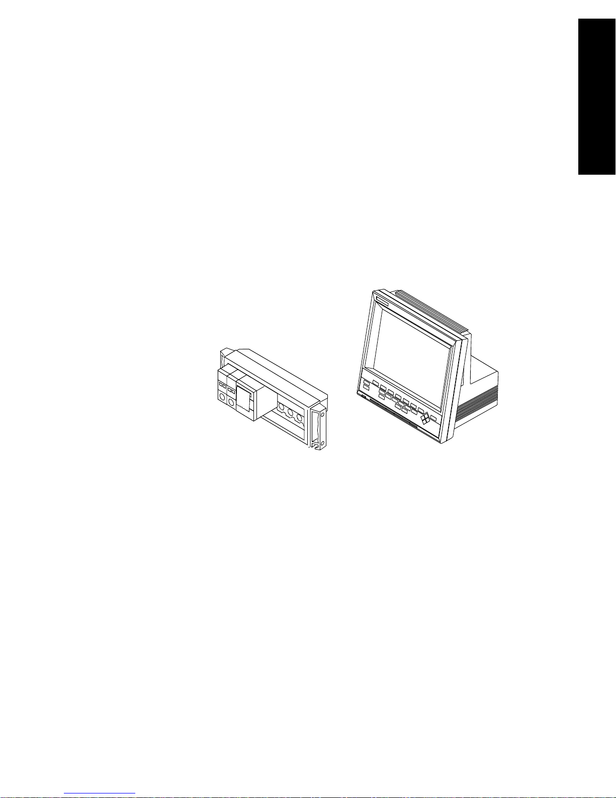
Display
Modules
Below are labeled diagrams of the display modules provided by Philips
Medical Systems. The control panel is described in more detail in the
following sections
V26 Patient Monitors
.
M1095A Flatscreen Display Module
1-6 The CMS and V24 and V26 Patient Monitors
M1092A / M1094B CRT Display Module
Page 29
Introduction
V24 and V26
Patient
Monitor
Each V24 and V26 Patient Monitor consists of two individual parts.
1. One of two types of Display Modules, depending on the particular
model monitor you have purchased—either:
a. A monochrome display with control panel supporting the V24,
or
b. A color flat panel display with control panel supporting the
V24C, the V24CT, the V26C and the V26CT.
2. The Rack with Parameter Modules
The CMS and V24 and
V26 Patient Monitors
The V24, V24C and V26C are powered by connection to an AC power
supply. The V24CT and V26CT can be powered by rechargeable batteries
or by connection to an AC power supply. See “V26CT/V24CT Power
Supply” on page 1-14.
The CMS and V24 and V26 Patient Monitors 1-7
Page 30

Introduction
The CMS and V24 and
Control
Panel
V26 Patient Monitors
The control panel consists of softkeys, hardkeys and alarm lamps.
Softkeys The softkeys perform multiple functions. Their functions correspond to
the labels displayed at the bottom of the screen. When no softkey labels
are on the screen, the softkeys do not function.
Hardkeys The hardkeys have only one function defined by the label on the key.
The hardkeys are labeled in blue. Each one of these keys gets you into a
level where adjustments and changes can be made or performs an
immediate action. The keys are labeled according to their function, for
example, key allows you to start a recording of a
Realtime Record
waveform.
Note—If you are using the M1167/77A system with the External Alarm
Device, the handheld keypad can be used to operate the system and to
enter data. It contains all the hardkeys and softkeys available on the
control panel of the other systems.
1-8 The CMS and V24 and V26 Patient Monitors
Page 31

Introduction
Alarm Lamps The alarm lamps are lit when a red or yellow alarm condition exists.
CMS Control Panel
Alarm Lamps
The CMS and V24 and
V26 Patient Monitors
Silence/
*
Reset
Suspend
*
Alarms Suspended Lamp
Note—Earlier versions of the V24 feature a key instead of the
Trends/Calcs
*
Main
Screen
Other
Patients
Monitor
Setup
Realtime
Record
Procedures
*
Delayed
Record
Trends/
Calcs
Module Alarms
Setup
*
V24 and V26 Patient Monitor Control Panel
Trends
key.
Confirm
*
The CMS and V24 and V26 Patient Monitors 1-9
Page 32

Introduction
The CMS and V24 and
The
Handheld
Keypad
V26 Patient Monitors
(CMS only):
The handheld keypad consists of the same softkeys and hardkeys that
are available on the control panel. In addition, the keypad provides data
entry keys which enable you to enter letters, numbers, punctuation
marks, and arithmetic symbols.
Note—The handheld keypad is the main means of operating the
M1167/77A System with External Alarm Device. Do not remove the
keypad from systems with touch or mouse/trackball operation as it is
still required to perform certain tasks.
Softkeys and
Hardkeys
The softkeys and hardkeys on the keypad are in the same relative
position and operate in the same manner as the keys on the control
panel.
Data Entry
The data entry keys are located on the bottom half of the keypad.
Keys
1-10 The CMS and V24 and V26 Patient Monitors
Page 33

Introduction
t
t
t
• To enter numbers and arithmetic symbols (labeled in white), simply
press the keys you want.
• To enter letters and punctuation marks (labeled in blue), press the
key. The lamp in the key lights up and remains on
Shif
until is pressed again. The softkeys and hardkeys work as
Shif
Shif
normal.
The CMS and V24 and
V26 Patient Monitors
External
Alarm
Device
(CMS only):
Since the External Alarm Device is used only with commercially available
ITE displays that do not have a control panel, it contains all the alarm
lamps, the Alarms Suspended Lamp and the loudspeaker. It does not
contain any hardkeys or softkeys and therefore can only be used in
conjunction with the Handheld Keypad. The Handheld Keypad can be
mounted onto the External Alarm Device as illustrated below.
The CMS and V24 and V26 Patient Monitors 1-11
Page 34

Introduction
The CMS and V24 and
Hardkey
Functions
V26 Patient Monitors
Silence/Reset
- press to silence an alarm or alarms that are sounding
or, if alarms are latching, to reset them.
Suspend
- press to suspend or switch on all alarms. The current state
is indicated by the Alarm Suspend Lamp.
Main Screen
Change Screen
- press to return to the main monitoring screen.
- (CMS only) press to change between screen layouts
or to access a 2nd or 3rd display. You can also freeze any wave
movement on the screen (INOPs, alarms and numerics are not affected).
Realtime Record
- press to record pre-selected waves onto a system
recorder or a bedside recorder.
Delayed Record
- press to record pre-selected waveforms that are no
longer on the monitor screen.
Alarms
- press to enable you to suspend or switch on alarms, set and
review alarm limits, enter Monitor Standby, or set the alarm volume.
Other Patients
- press to enable you to view data from other beds in
your group.
Monitor Setup
- press to enable you to pre-select certain system
characteristics.
Procedures
- press to enable you to set up and perform procedures
such as Cardiac Output, Wedge Pressure (CMS only), ST analysis, Drug
Calculations, admit and discharge patients, or end a particular patient
case and transfer patient data.
Trends/Calcs
- press to enable you to view vital signs and graphical
trends, make and review calculations, print reports and mark events to
view in graphs.
Module Setup
- press to enable you to change or adjust parameter
settings, switch parameters on or off, or set up parameters.
Arrow
1-12 The CMS and V24 and V26 Patient Monitors
Keys
Page 35

Introduction
The arrow keys consist of up/down/left/right keys. They only function
when illuminated. The arrow keys allow you to move between areas on
operating screens to enable you to change or adjust settings, perform
procedures, or make changes to the screen display.
The CMS and V24 and
V26 Patient Monitors
Confirm
Key
This key functions only when it is illuminated. A prompt message “...press
CONFIRM...” appears on the screen when you need to use it.
Airway Gases/Ventilation
- (CMS only) Press to view airway gases or
ventilator waves and numerics.
The CMS and V24 and V26 Patient Monitors 1-13
Page 36

The CMS and V24 and
V26CT/V24CT Power Supply
V26CT/V24CT Power Supply
V26 Patient Monitors
The V24CT and V26CT are powered by an external AC (line power) or by
their own internal battery power supply. Your monitoring needs will
determine which power source is used. We recommend that you plug
the monitor into line or AC power whenever the monitor is not being
moved or used, or for long term bedside monitoring. When transporting
a patient or when monitoring in a remote area, where AC power is not
feasible, use battery power.
WarningWarning
Do not disconnect the power cord from the monitor and leave it
connected to the AC power source. This could cause damage to
the power cord. Instead, keep the power cord connected to the
monitor and unplug it from the AC power source.
Battery
Power
Supply
The power cord must be inspected periodically for cracks or
exposed metal parts. Replace immediately if there are any
cracks, exposed metal parts, or any other signs of wear and tear.
The V24CT and V26CT can be powered by 1 or 2 sealed 12 Volt lead-acid
batteries with capacity. The rate of battery discharge is dependent on
temperature and power load. The power load is a function of the
number and type of parameter modules as well as parameter settings
being used. The battery life for the V24CT and V26CT ranges from
approximately 30 minutes for a fully loaded system operating on one
new and fully charged battery to:
• approximately 1 hour for a fully loaded system operating on two
new and fully charged batteries when loaded with the following
parameter modules:
ECG/Resp, NBP, SpO
• approximately 1 hour 15 minutes for a minimally loaded system
operating on two new and fully charged batteries when loaded
with the following parameter modules:
ECG/Resp, NBP, SpO
, Pressure, Recorder and
2
, Pressure.
2
1-14 The CMS and V24 and V26 Patient Monitors
Page 37

V26CT/V24CT Power Supply
Battery life includes the time during the low battery alarm (INOP
“Recharge Batteries”) until the unit shuts off.
Battery
Specifications
We recommend you use 2 fully charged batteries to get the optimum
battery life when using the battery power supply.
• 1 or 2 lead-acid batteries.
•12 Volt.
• Up to 1.25 hours battery capacity typical on two new fully charged
batteries at 25°C, depending on modules used in the product.
Note—Charging time is 4 hours to 90% of full capacity if the monitor is off.
16 hours to 90% of full capacity if the monitor is on.
Confirm
Trends/
Calc
Delayed
Record
Module
Setup
Battery
Charging
Battery
Charged
AC
Power
The CMS and V24 and
V26 Patient Monitors
Note—When AC is connected and the monitor is on, the Battery Charge
LEDs may take some time to cycle to the appropriate charge indication
and may underreport battery capacity during this setting period. Use the
fuel gauge rather than the Battery Charge LEDs during this period to
estimate battery capacity or turn the monitor off to accelerate the charge
setting time.
See Chapter 12, “Battery Information (V24CT and V26CT only)” for
additional information on battery operation and Battery Charge LEDs and
indicators.
The CMS and V24 and V26 Patient Monitors 1-15
Page 38

The CMS and V24 and
Parameter Modules
Parameter Modules
V26 Patient Monitors
The parameter modules have one or more hardkeys on the front. The
key labeled with the parameter name is called the Setup key, which gets
you directly into the setup screen for that parameter. When you press
the Setup key on the front of the module, and get into the parameter
setup window or task window, a light appears above the key.
The connector socket on the front of each module is the same color as
the corresponding connector plug on the transducer or patient cable.
ECG
M1001B
T
Light for
setup key
ECG
Parameter
setup key
80x80
Connector for
patient cable
or transducer
Note—If a “T” is present on the front of a module, certain parameter
settings may be transferred with that module when it is moved from one
rack to another. This behavior is dependent on a setting made in a
12
PIN
1-16 The CMS and V24 and V26 Patient Monitors
Page 39

Parameter Modules
special Service Mode, either by your biomedical engineering department
or the Philips service engineer. You can find a description of this behavior
(called “Parameter Settings Transfer”) in Chapter 3.
The CMS and V24 and
V26 Patient Monitors
Symbols to
Indicate Key
Functions
As detailed in the table below, some modules used with the M1046A CMS,
and M1205A V24/26 patient monitors now use symbols, instead of words,
to indicate the function of some keys. If the monitor’s Reference Manual
tells you, for example, to select the START key, you should press the key
marked with the corresponding “start” symbol.
The design change also means that you will now find the module’s
product number (for example M1032A) on the rear of the module’s
housing, not on the front. Although the new modules do not show the
letter “T” on the housing, all modules retain their capability to transfer
parameter settings from one monitor to another.
Symbol Name Function Which Modules?
ZERO zero a pressure transducer Pressure (M1006B), including
option C01
Press
pressure outlet connector Pressure (M1006B) option C01
Out
Monitor initiates transfer from
Data Transfer Module (M1235A)
module to monitor
Module initiates transfer from
monitor to module
START start measurement CCO/C.O. (M1012A)
CCO/C.O. including option C10
Cal calibrate SvO
(M1021A), tcpO2/tcpCO2
2
(M1018A)
Mainstream CO
The CMS and V24 and V26 Patient Monitors 1-17
(M1016A)
2
Page 40

Parameter Modules
Parameter modules can be plugged into the following types of rack:
The CMS and V24 and
V26 Patient Monitors
Rack Type Mounting Comments
CMS Patient Monitoring System
Integral Rack This is fitted to the front of
the M1046A computer
module.
Cannot be used with
the M1167/77A CMS
Patient Monitoring
System. 8-slot rack.
Satellite Rack You can have one or more
satellite racks attached to
an I.V. pole, bedside or
wall.
Can be used with all
CMS Patient
Monitoring System.
Available as 6-slot or
8-slot rack.
V24 and V26 Patient Monitor
8-slot Satellite
Rack
(Standard)
Same as Satellite Rack for
CMS.
Only one Satellite
Rack can be used
with a V24 and V26
Patient Monitor.
6-slot Satellite
Rack
(Optional)
Same as Satellite Rack for
CMS.
This can also be mounted
to the back of the M1205A
V24CT and V26CT
Monitors
Caution
When the rack is mounted in close proximity to any intravenous infusion
equipment, do not let saline solution get onto the rack or parameter
modules. Severe damage to the equipment can result if saline solution
leaks into the connectors at the rear of the modules.
You can plug the parameter modules into the rack and remove them as
you require them. The number of modules you can plug in depends on
the type of rack and the model of monitor you have ordered.
1-18 The CMS and V24 and V26 Patient Monitors
Page 41

Parameter Modules
For most types of parameter modules, the system allows only one of each
type per patient (ECG, for example). Other types of modules allow more
than one per patient (Invasive Pressure, for example).
If too many modules or an unsupported module are plugged in, a message
detailing where the extra module is, appears in the system message field:
Currently ignored module in rack position R-P
where:
R is the number of the rack
(e.g. 1=integral rack, 2=first satellite rack,...
or 1=first satellite rack, 2=second satellite rack,...
P is the slot number in that rack
(counted from left to right)
The message
Unrecognized module in rack position R-P
is displayed if an unknown module is plugged into the rack.
The CMS and V24 and
V26 Patient Monitors
Note—Since the V24 and V26 Patient Monitors only support one module
rack, R will always be 1.
The CMS and V24 and V26 Patient Monitors 1-19
Page 42

The CMS and V24 and
Operating Levels
Operating Levels
V26 Patient Monitors
There are three types of screens which you will see on the display
module. The three types of screen and the interconnections between
them are shown below.
Standard
Display
Control
Panel
1st Level
2nd Level
Selection
Window
Task
Window
1-20 The CMS and V24 and V26 Patient Monitors
Page 43

Operating Levels
Main Screen This display shows the waveforms and numerical readouts of the
parameters you have chosen to monitor, alarms, INOP messages, bed
label, date and time, and arrhythmia messages (when assigned).
You can configure the number and position of the waveforms on the
display screen. The numerics are aligned with the corresponding waves.
The numeric information is updated every two seconds. With the color
model, the numeric appears in the same color that you have assigned to
the corresponding waveform.
The CMS and V24 and
V26 Patient Monitors
The hardkey always returns you directly to the Main
Main Screen
Screen.
Note—The Main Screen of the V24 and V26 Patient Monitors include
Alarm Volume Control and QRS Volume Control Bars (see figure below)
The CMS and V24 and V26 Patient Monitors 1-21
Page 44

Operating Levels
The CMS and V24 and
ICU Adult 10 JAN 95 20:05
II
V26 Patient Monitors
CHANNEL #1
LAYOUT: #1 NON-OVERLAP
CHANNEL #2
CHANNEL#3
CHANNEL #4
F HR
ABP
PLETH
CO
2
1mV
120
0
SpO
SQI
2
40
0
Alarm Vol 165
QRS Vol 150
HR
70
ST1
ST2
ABP
135/72 (94)
PAP
0.3
-0.2
PULSE
70
34/16
(23)
SpO
2
97
ETCO
2
20
0
IMCO
AWRR
2
NBP
37
19:47
115/65
(81)
NUMERICS
1-22 The CMS and V24 and V26 Patient Monitors
Page 45

Operating Levels
Selection
Window
This is the first operating level where you can choose a specific activity or
function.
You get into a Selection Window by pressing one of the blue-labeled
hardkeys on the control panel.
When you get into the Selection Window the bottom line is always active.
This is indicated by a bar below the keys and the yellow labeling. The
selection can be changed within the Selection Window one line at a time.
For information on how to change the selection see page 1-25.
There is also an arrow symbol in the Window that moves along the
selected line when the cursor keys are pressed. To enter the Task
Window to which the arrow is pointing, press .
Confirm
The CMS and V24 and
V26 Patient Monitors
The CMS and V24 and V26 Patient Monitors 1-23
Page 46

Operating Levels
The CMS and V24 and
Task
Window
V26 Patient Monitors
This is the second operating level, which allows you to make changes or
adjustments to the parameters and screen displays, or to perform
procedures. Each parameter or procedure has a series of Task Windows.
There are two ways to get into the second operating level:
via the Selection Window,
or for parameters:
by pressing the Setup key on the parameter module.
1-24 The CMS and V24 and V26 Patient Monitors
Page 47

Operating Levels
Getting into
the
Operating
Levels
Before you can start to make adjustments or changes to the parameters or
perform a procedure, you need to know how to get into the operating
levels and how to navigate through the selections. Follow the procedures
below to get into the Selection and Task Windows.
Selection Window
1. Press the blue-labeled hardkey for the function you require.
2. When you get into a Selection Window, the bottom line is always
active. Select the line with the parameter or function you require, by
pressing the same hard key again that got you into the selection
window, or use the arrow keys if they are illuminated.
3. Press either the softkey corresponding to the parameter or function
you require or . This gets you into the Task Window.
Confirm
For example, to get into the Noninvasive Blood Pressure (NBP) Task
Window:
1. Press the hardkey
Module Setup
2. If it is not already active, select the line containing NBP by pressing
Module Setup
again.
The CMS and V24 and
V26 Patient Monitors
3. Press the softkey to get into the Noninvasive Blood Pressure
NBP
Task Window.
Task Window
There are two ways to get into a parameter Task Window, either:
via the Selection Window,
or
by pressing the Setup key on the parameter module which gets you
directly into the Task Window.
Getting into other Task Windows for functions like Other Patients or
Monitor Setup is only possible via the Selection Window. In the Task
Window there are separate keys. The selections that are currently active
for the parameter or function you have chosen are indicated by yellow
labeling. In addition the selected keys appear to be “pushed in” on the
screen.
The CMS and V24 and V26 Patient Monitors 1-25
Page 48

The CMS and V24 and
Operating Levels
V26 Patient Monitors
There are two reasons for changing the selection in the Task Windows:
you will either want to move to the next Task Window, or make an
adjustment to a setting.
1. To move to the next Task Window, press the softkey for the
function you require, for example . This gets you
Filter/Mon/Diag
into the Filter/Mon/Diag Task Window where you can make any
necessary adjustments.
2. To make an adjustment, change the selection by pressing the
softkey for that window again, until the adjustment or change you
want is active, or use the arrow keys if they are illuminated.
1-26 The CMS and V24 and V26 Patient Monitors
Page 49

Touch or Mouse/Trackball Operation
The M1167A/77A systems also allow connection of XGA displays, enabling
touch (requires touchscreen displays), mouse or trackball operation of
the monitor. Since these displays do not contain a control panel, there are
slight differences in operating the system. The following sections contain
the instructions specific to touch, mouse or trackball operation.
V24C and V26C monitors with option T01 allow touch operation in
addition to the standard operation. Mouse and Trackball operation is not
available for the V24 and V26 monitors.
Touch or Mouse/Trackball Operation
The CMS and V24 and
V26 Patient Monitors
The CMS and V24 and V26 Patient Monitors 1-27
Page 50

The CMS and V24 and
Touch or M ouse/Trackball Operation
Main Screen The layout of the main screen is basically the same as with other CMS,
V24 and V26 Patient Monitoring Systems, with the only exception that it
contains three additional buttons: the Silence/Reset button, the Suspend
V26 Patient Monitors
button (both in the upper right corner of the display) and the Control
Panel button (in the lower right corner of the display).These buttons are
touch-responsive and can be used alternatively to the hardkeys of the
control panel or the handheld keypad.
Silence/
Reset
Suspend
Control
Panel Task
Window
Control
Panel
Note—Do not remove the keypad from systems with touch or mouse/
trackball operation as it is still required to perform certain tasks.
The Control Panel Task Window contains most of the hardkeys found on
the control panel of non-touch systems. See “Hardkey Functions” on
page 1-12 for detailed descriptions of these keys. You can access the
Control Panel Task Window by touching the Control Panel symbol in the
lower right corner of the main screen display.
1-28 The CMS and V24 and V26 Patient Monitors
Page 51

Touch or Mouse/Trackball Operation
Control Panel Task Window
The CMS and V24 and
V26 Patient Monitors
General
Touch/
Mouse/
Trackball
Operation
(CMS only)
If a touch-responsive object or area of the screen is selected (either by
touch or by mouse-click), a white ‘+’ appears and the area is surrounded
by a white frame. In addition, an audible click is issued. The white frame
disappears automatically when the object is released. If an object or area
of the screen that is not touch-responsive is touched, a white ‘x’ appears
in the selected area.
Note—When using a mouse/trackball, the white ‘+’ and ‘x’ signs appear,
wherever the mouse/trackball pointer is currently located. This indicates
touch-responsive areas before they are actually selected by mouse-click.
The CMS and V24 and V26 Patient Monitors 1-29
Page 52

Touch or M ouse/Trackball Operation
The CMS and V24 and
Touch-
Touch-responsive objects and areas of the screen include:
Responsive
Objects
V26 Patient Monitors
• Numerics and Waves - When a numeric or wave is selected, the
respective parameter setup window opens up.
• Alarms/INOP messages - Selecting an Alarm or INOP Message
opens the alarm messages window.
• Task Windows/Selection Windows - All softkeys displayed in
Task Windows and Selection Windows are touch-responsive.
When a Task Window/Selection Window is open, a selection of any
area outside this window (except the Silence/Reset and Suspend
keys) will close the task window. Selecting the black x in the
corner of the Task Window label also closes the Window. Closing
a Task Window returns you to the Main Screen.
• Items/Selections - All Items and all Selections within Task
Windows can be directly selected by touch or mouse-click without
the Select Item softkey or the arrow keys.
• Arrow Keys - Depending on the application, buttons are provided
to perform the task of the arrow keys.
• Confirm Button - A confirm button is displayed in the lower right
corner of the task window every time a confirm is required.
• Application Windows - Split Screen, oxyCRG and CSA Display
contain touch-responsive areas which lead to the respective task
windows. Please refer to Chapter 3 of this manual for further
details.
• Application-specific buttons - Touch/Mouse/Trackball
Operation has special implications for the Vital Signs, Graph
Trends and Calculation Task Windows (see Chapter 8 Trends and
Calculations for details), for the Patient Admit Task Window (see
Chapter 7 Admit/Discharge/End Case for details), for the ST
Analysis Task Window (see Chapter 14 ECG and ECG/Respiration
Module Section for details) and for defining screen labels and
adjusting the date and time (see Chapter 3 Setting up your
Monitor for details).
1-30 The CMS and V24 and V26 Patient Monitors
Page 53

Touch or Mouse/Trackball Operation
Alphanumeric
Entries
A Touchboard can be accessed when alphanumerical data needs to be
entered. This is an alternative to the entry of data with the handheld
keypad. The Touchboard can be activated with the “Touch Board” softkey
e.g. from the Patient Admit Task Window.
The CMS and V24 and
V26 Patient Monitors
The Touchboard Task Window contains a subtitle which references the
Task Window from which the Touchboard was accessed. Data entry can
be performed for one item at a time.
Press to save edited data.
Press or to navigate through the editable
Next Item
Previous Item
items of the Task Window the Touchboard was accessed from.
Press to return to the Task Window the Touchboard was accessed
Back
from.
The CMS and V24 and V26 Patient Monitors 1-31
Page 54

Touch or M ouse/Trackball Operation
The CMS and V24 and
Disabling
Touch/
Mouse/
V26 Patient Monitors
Trackball
Operation
In order to prevent unintended or uncontrolled operations of the
monitor, touch operation must be disabled while cleaning the
touchscreen. To disable touch and mouse/trackball operation press and
hold or click and hold the control panel button in the lower right corner
of the main screen for at least four seconds. A padlock icon over the
control panel button indicates when touch and mouse/trackball
operation is disabled. To re-enable touch and mouse/trackball operation
press and hold or click and hold the padlock icon for at least two
seconds. The control panel button will reappear.
Note—If a task window is opened or the monitor is put in standby mode
via the handheld keypad while touch and mouse/trackball operation is
disabled, touch any area of the screen to return to the main screen. The
padlock icon will be displayed.
1-32 The CMS and V24 and V26 Patient Monitors
Page 55

The CMS Computer Modules
The signals from the parameters being monitored are transmitted to the
computer module, where they are processed and then displayed on the
screen as waveforms and numerical readouts.
The CMS Computer Modules
The CMS and V24 and
V26 Patient Monitors
M1046A
Computer
Module
The M1046A Computer Module is for use with the Philips M1165/66A and
the Philips M1175/76A CMS Patient Monitoring System.
Maximum Voltages
ECG Output and Defib. Marker Input 3.2 V p-p
Connector for satellite rack 60 V
The parameter module rack can be attached to the computer module, or a
blank panel can be fitted to the computer module if you want to use a
satellite parameter module rack.
The CMS and V24 and V26 Patient Monitors 1-33
Page 56

The CMS Computer Modules
The CMS and V24 and
M1046B
Computer
Module
V26 Patient Monitors
The M1046B Computer Module is for use with the Philips M1167/77A
CMS.
Maximum Volt age
ECG Output and Defib. Marker Input 3.2 V p-p
The parameter modules are inserted into one or several satellite racks.
They cannot be attached to the front of the computer module.
ECG Output
Applies to both the M1046A and M1046B Computer Modules.
and
Defibrillator
Marker Input
1-34 The CMS and V24 and V26 Patient Monitors
The ECG output and defibrillator marker input connector on the
computer module is used during cardioversion to provide an ECG
waveform for synchronizing a defibrillator. It is also used to receive a
marker pulse from the defibrillator for indicating the defibrillator
discharge in the ECG waveform on the monitor display.
If you are using a Philips defibrillator without a built-in recorder, the
marker pulse from the defibrillator is returned to the monitor. If the
Philips defibrillator has a built-in recorder, then the marker pulse is
returned to that recorder rather than to the monitor. The ECG output
can also be used for other applications, such as synchronizing intraaortic balloon pump systems.
Page 57

The V24 and V26 Parameter Module Rack
The V24 and V26 Parameter Module Rack
The V24 and V26 parameter module rack is attached to the display module
by a cable to a connector on the left side of the display module. In
addition, the V24CT and V26CT allow you to dock a 6-slot rack directly to
the mainframe.
WarningWarning
Do not connect a second rack by a cable when using the V24CT or
V26CT with a 6 wide rack docked to the mainframe. Docking a
second rack by a cable may disrupt module communication.
The signals from the parameters being monitored are transmitted to the
internal computer, where they are processed and then displayed on the
screen as waveforms and numerical readouts.
The CMS and V24 and
V26 Patient Monitors
The CMS and V24 and V26 Patient Monitors 1-35
Page 58

The CMS and V24 and
Operating Rules to Remember
Operating Rules to Remember
V26 Patient Monitors
• Pressing key always returns you to the Main Screen.
• To get into a Selection Window press a hardkey.
• What is labeled in yellow and appears “pushed in” is active.
• Softkeys function only in the Selection and Task Windows (with
the exception of the Alarm Volume Control and the QRS Tone
Volume Control on the V24 and V26 Patient Monitors).
• The parameter module Setup key gets you directly into a Task
Window.
Main Screen
• The arrow keys and key are illuminated when available
Confirm
for use.
1-36 The CMS and V24 and V26 Patient Monitors
Page 59

Performance Specifications of the Philips Displays
Performance Specifications of the Philips Displays
M1095A
Flatscreen
Display
M1094A/B
and M1092A
CRT Display
Useful Screen:
(±5% unless otherw ise noted)
Pixel Size 0.33 mm x 0.33 mm
Storage Time at 25 mm/sec 5.5 second s
Trace Spee ds 6.25, 12.5, 25, 50 mm/sec ±10%
Useful Screen:
(±5% unless otherw ise noted)
158 mm x 211 mm (6.2” x 8.3”)
180 mm x 225 mm (7.1” x 8.9”)
The CMS and V24 and
V26 Patient Monitors
M1097A
#A02 XGA
Flatscreen
Display
Pixel Size 0.22 mm x 0.35 mm
Storage Time at 25 mm/sec 6 seconds
Trace Spee ds 6.25, 12.5, 25, 50 mm/sec ±10%
Useful Screen:
(±5% unless otherw ise noted)
Pixel Size 0.297 mm x 0.29 7 mm
304.1 mm x 228. 1mm (12” x 9”)
The CMS and V24 and V26 Patient Monitors 1-37
Page 60

The CMS and V24 and
Using an ITE Display
Using an ITE Display
V26 Patient Monitors
The M1167A/77A CMS Patient Monitoring System provides means for
customers to use ITE displays. There are several restrictions associated
with this option. Since the display is used as part of a medical device
within the patient vicinity, there are additional requirements to be
fulfilled in order to be in compliance with the European Council
Directive 93/42/EEC (Medical Device Directive) and with FDA
recognized consensus standards:
•Safety
•EMC
• Performance Requirements
Safety 1. The display must either comply with the requirements of the:
EN60601-1 +A1 +A2 {IEC601-1 +A1 +A2}, or
it must conform to the requirements of an IEC XXX electrical
safety standard and fulfill specific requirements according to the
EN60601-1-1 +A1 {IEC601-1-1 + A1} to provide the same level of
safety as EN60601-1 {IEC601-1}:
– The display must be constructed or protected so that spillage
of liquids does not wet parts of the display which may cause a
safety hazard (IEC601-1; 44.3).
– The ITE display must be used with an isolation transformer
(e.g. Philips M1389A), if the enclosure leakage current
exceeds the requirements of EN60601-1/IEC601-1 (normal
and single fault condition). The power cable must be secured
so that the transformer cannot be disconnected without the
use of a tool.
2. A test of the Enclosure Leakage Current (normal and single fault
condition) of the complete system, including the display, has to be
performed and documented.
1-38 The CMS and V24 and V26 Patient Monitors
Page 61

Using an ITE Display
EMC 1. The display must either fulfill the requirements of the EN60601-1-2
{IEC 601-1-2}, or
it must conform to the requirements of the EMC standard for ITE
devices, EN50082-1: 1997 and EN50081-1 / CISPR 22.
2. The video cable between M1167A/77A CMS Patient Monitoring
System and the ITE display must not exceed a length of 3.0m. For
cables exceeding 3.0m EMC testing according to IEC 801-4:1988 has
to be done.
Performance
Requirements
Specification Requirement or Value Units
Resolution (pixel addressability) 1024 x 768 Dots x lines
Vertical Refresh Rate 60 Hz (non-interlaced)
Red, Green and Blue Video Inputs ~0.7 V p-p
Vertical & Horizontal Multi-Sync Inputs 5 V TTL
Video-Cable Connector HD15male
Philips cannot assure compliance with the ANSI/AAMI EC-13 Standard for
Cardiac Monitors, Heart-rate Meters and Alarms when using ITE displays.
Compliance with the ECG aspect ration and 25 mm/s
specifications can only be assured when using the Philips Displays
M1092A, M1094B and M1095A. In addition, the following display
specifications are recommended:
±10% sweep-speed
The CMS and V24 and V26 Patient Monitors 1-39
Page 62

Using an ITE Display
1-40 The CMS and V24 and V26 Patient Monitors
Page 63

Getting Started
Now that you have been introduced to the monitor you are
probably ready to start using it. This chapter will help you get
started. It contains the following sections:
• Setting up the Monitor (V24 and V26 only) . . . . . . . . . . . . 2-2
• Setting up the Parameter Modules . . . . . . . . . . . . . . . . . . . 2-5
• Attaching the Patient . . . . . . . . . . . . . . . . . . . . . . . . . . . . . . 2-6
2
Getting Started 2-1
Page 64

Getting Started
Setting up the Monitor (V24 and V26 only)
Setting up the Monitor (V24 and V26 only)
1. Attach the parameter module rack to the display module by a
cable to the connector on the left side of the display module. If you
are using the V24CT or V26CT you can attach the 6-slot rack to the
back of the mainframe display without the need for a cable. The
two components will snap or dock together.
2-2 Getting Started
Page 65

Setting up the Monitor (V24 and V26 only)
2. If you are using the V24CT and V26CT and the batteries are not
already in place, insert 2 Philips 40488A 12 Volt 2.3 Amp-hour sealed
lead-acid batteries into the spring-loaded battery door in the back of
the monitor. The batteries should be inserted with the grey Philips
battery label facing upwards and the contacts pointing into the
monitor. The batteries will snap or click into place when properly
inserted.
Getting Started
0
0
0
0
0
A
Caution
Philips Medical Systems recommends you fully charge the batteries
before using the V24CT or V26CT for the first time. Plug the monitor into
an AC power supply (line power) for an initial charging cycle. When the
monitor is plugged in and the power is off, it takes approximately four
hours for the batteries to reach a charge of 90% capacity and nine hours
for the batteries to be fully charged. If the monitor is plugged in and the
power and external battery charger is on, it takes approximately 16 hours
to charge the batteries.
3. If using an AC power supply, plug the power cord into the power
source.
Getting Started 2-3
Page 66

Getting Started
Setting up the Monitor (V24 and V26 only)
4. Switch on the system using the power On\Off switch. A self test is
then performed.
WarningWarning
Connecting the Philips monitoring network (SDN) cable when the
product is powered on is not supported. Error codes and Philips
monitoring network (SDN) interface lock-up may occur. Power cycling
the product will recover the product. No permanent damage will result.
To prevent unintentional disruption in monitoring, be sure the SDN
interface cable is properly secured at both ends when connecting to the
Philips monitoring network (SDN).
2-4 Getting Started
Page 67

Setting up the Parameter Modules
1. Decide which parameters you want to monitor.
2. Make sure the appropriate modules are plugged into the rack. If not,
insert the module into the rack until the lever on the base of the
module clicks into place. To remove a module, press the lever
upwards and pull the module out. (See diagram below.)
Setting up the Parameter Modules
Getting Started
3. Check that you have the correct patient cables and transducers
plugged into the modules. The module connectors are color-coded
to the patient cables and transducers, for easy identification.
Your monitor may have Parameter Settings Transfer set ON. To
understand the effect this has when using modules with the “T” label, turn
to Parameter Settings Transfer in Chapter 3.
Getting Started 2-5
Page 68

Getting Started
Attaching the Patient
Attaching the Patient
1. Attach the electrodes, probes, transducers, and insert pressure
catheters as required for monitoring the patient.
2. Connect the electrodes, probes and transducers to the appropriate
modules.
After less than 10 or 20 seconds you should see a display on the screen
similar to the one under “Main Screen” in Section 1. The number of
waveforms depends on the waveforms you have selected to have
displayed and also on the model of your system.
The numerics are aligned with the corresponding waveform.
2-6 Getting Started
Page 69

Attaching the Patient
Adjusting
Screen
Contrast
V24 and V26:
The brightness or contrast of the screen display can be adjusted by using
the dial located behind the edge of the display, on the lower right side of
the monitor. The V24 uses a contrast control. V24C, V24CT, V26C and
V26CT are equipped with a brightness control. Make sure that all of the
screen information is visible.
Getting Started
Screen Brightness Control
(Model V24C, V26C
V24CT, V26CT)
Screen Contrast Control
(Model V24)
CMS:
The brightness and contrast of the screen display can be adjusted by
means of the two dials underneath the hardkeys.
Follow this procedure to achieve the optimum screen display:
1. Turn the brightness and contrast controls to their maximum
settings.
2. Slowly turn the brightness and contrast controls down to the lowest
acceptable position where the display can still be seen clearly. The
most acceptable position will be dependent upon the surrounding
light conditions. Please ensure that all the screen information is
visible.
Getting Started 2-7
Page 70

Getting Started
Attaching the Patient
Starting
Monitoring
Screen
Messages
The patient's vital signs are now appearing on the screen. The preconfigured default settings for the parameters and screen display, that
were set up at installation or have been stored in the module
(“Parameter Settings Transfer”), are active.
If you want to make changes to the screen display see the section
“Configuring the System”. If you want to make changes to the
parameter settings see the individual parameter sections.
Switch the system alarms ON (by pressing the key so that
the Alarm Suspend lamp goes out). The patient is now being monitored.
Two types of messages appear at the top of the display screen:
• Prompt messages - these instruct the user to perform an action
• Status messages - these give information about the current
situation. For instance:
“sync output not available, plug-in ECG module''
Suspend
2-8 Getting Started
Page 71

Attaching the Patient
this message stays as long as the ECG module is not plugged in.
Prompt and status messages are displayed either in the appropriate Task
Window, or at the top of the Main Display screen, depending on the
operating level.
On the Main Screen display the prompt and status messages are shown
below the alarm and INOP messages.
Prompt messages appear for 3 seconds.
Status message are displayed in rotation for 3 seconds each.
Reserving a
Channel
In the Task Window the prompt and status messages remain until the
appropriate user action is performed.
A parameter module may be turned OFF, but left in the rack. The empty
channel where the waveform should be still appears on the Main Screen.
There is no waveform, waveform label, or numeric. Another wave may
use its screen channel temporarily, but will be discarded as soon as the
assigned wave is reactivated.
This ensures that particular waveforms can always be allocated to the
same place on the Main Screen, and avoids inconsistencies in the
waveform display of different patients in the same department.
Note—If trend data for this patient is to be collected, old data from a
previous patient should be deleted. The old data will be automatically
deleted if the monitor has been shut off for three hours or more. See
“Discharging a Patient/Ending a Case” on page 7-9 for more information.
Getting Started
Getting Started 2-9
Page 72

Attaching the Patient
Getting Started
Power
Failure
If a power failure occurs, any alarm conditions that were stored in the
monitor will NOT be retained when power is restored. Settings such as
alarm limits stored in “T” modules ARE retained - see “Parameter
Settings Transfer” on page 3-61.
Caution
You are advised to check all the monitor settings after any power failure.
The monitor reacts according to the length of the power failure:
Less than 60 seconds Patient Data Management data and all
settings retained.
Less than 3 hours Patient Data Management data retained. All
settings revert to user defaults.
More than 3 hours Patient Data Management data not retained.
All settings revert to user defaults. Time
setting may be lost if not networked.
Patient
Information
Center
Monitor
Standby
2-10 Getting Started
If the monitor is connected to a Patient Information Center (78504 and
78508) and you select the same lead for ECG channels 1 and 2, the wave
is not displayed in channel 2 of the Patient Information Center.
If you want to stop patient monitoring, but keep all settings and Patient
Data Management information, you can switch the monitor into
“Monitor Standby”:
1. Press or
2. Press .
All waves and numerics disappear from the display, and all monitoring is
suspended. The word “Standby” appears in big letters on the screen.
Alarms / Volume Alarms
Monitor Standby
Page 73

Attaching the Patient
If your monitor is connected to a Philips patient care system while the
monitor is in standby, no parameter data from your monitor is sent over
the system. Instead, a message indicating that your monitor is in
“Standby” is sent to other beds in the system, and is displayed at the
central station. If your bed is configured to receive alarms, and another
bed in the system goes into alarm, the status message “Other Bed in
Alarm” is displayed on your monitor. You will hear the overview prompt
tone (two double beeps), but the Alarm Bed Task Window will not be
displayed.
To resume monitoring, simply press one of the keys (except )
Suspend
on the control panel on the front of the display or on the handheld keypad
(CMS only). The changes and adjustments that you made to the settings
before going into Monitor Standby are retained. Patient Data Management
information collected before going into Monitor Standby is also retained.
As all monitoring is suspended, no patient data is collected while the
monitor is in Monitor Standby.
The hardkey operates as usual when you are in Monitor
Suspend
Standby, so you can prepare the monitor alarm capability before you
resume monitoring.
Getting Started
Getting Started 2-11
Page 74

Getting Started
Attaching the Patient
2-12 Getting Started
Page 75

Setting up your Monitor
This chapter describes the characteristics of your system that
can be changed during monitoring, using the
key. It includes the following sections:
• Changing Display Screens . . . . . . . . . . . . . . . . . . . . . . . . . . 3-2
• Selecting a Screen . . . . . . . . . . . . . . . . . . . . . . . . . . . . . . . . . 3-3
• What you Can Configure. . . . . . . . . . . . . . . . . . . . . . . . . . . . 3-5
• Changes to the Configuration . . . . . . . . . . . . . . . . . . . . . . . 3-6
• Assigning Waves to Screen Channels . . . . . . . . . . . . . . . . . 3-8
• Selecting the Number of Waves. . . . . . . . . . . . . . . . . . . . . 3-13
• Changing the Wave Overlap. . . . . . . . . . . . . . . . . . . . . . . . 3-14
• Selecting Realtime Wave Speeds. . . . . . . . . . . . . . . . . . . . 3-15
• Displaying Split Screen Trends . . . . . . . . . . . . . . . . . . . . . 3-22
• oxyCRG Display. . . . . . . . . . . . . . . . . . . . . . . . . . . . . . . . . . 3-25
• CSA Display (CMS only). . . . . . . . . . . . . . . . . . . . . . . . . . . 3-28
• Configuring a Second Independent Display (CMS only) 3-32
• Adjusting the Volume Control . . . . . . . . . . . . . . . . . . . . . . 3-35
• Adjusting the Date and Time . . . . . . . . . . . . . . . . . . . . . . . 3-37
• Selecting Waves for Central Recorders . . . . . . . . . . . . . . 3-39
• Configuring Module, Bedside and Central Recordings . 3-40
• Other Patients Controls . . . . . . . . . . . . . . . . . . . . . . . . . . . 3-41
• The Status Log Function. . . . . . . . . . . . . . . . . . . . . . . . . . . 3-42
• The Monitor Revision Function. . . . . . . . . . . . . . . . . . . . . 3-43
• Changing Default Settings and Patient Category . . . . . . 3-44
• Changing the Patient Category . . . . . . . . . . . . . . . . . . . . . 3-45
• Changing the Configuration Set. . . . . . . . . . . . . . . . . . . . . 3-53
• Changing Operating Modes . . . . . . . . . . . . . . . . . . . . . . . . 3-55
• The Test Signals Function . . . . . . . . . . . . . . . . . . . . . . . . . 3-58
• Parameter Settings Transfer . . . . . . . . . . . . . . . . . . . . . . . 3-61
Monitor Setup
3
Setting up your Monitor 3-1
Page 76

Changing Display Scree ns
Next Display
Changing Display Screens
A display screen is a pre-selected arrangement of realtime waveforms,
numerics and overlayed application windows. A particular display
screen can, for instance, be created to monitor a patient during a
specific procedure in a department or unit.
There are five separate display screens which can be configured. The
default names of these screens are Screen A, Screen B, Screen C, Screen
D and Screen E. You can select additional screen labels (such as
Standard, or Surgeon) for these screens.
A softkey corresponding to each screen is available in the Change
Screen Task Window (CMS) or the Monitor Setup Task Window (V24
and V26). The display screen which is active is identified by an inactive
softkey for that screen.
You can change to one of the other screens at any time, by pressing one
of the other softkeys.
Monitor
You can reconfigure only the screen which is currently active. Once a
Setting up your
display screen has been configured, the settings remain either until the
user changes them, or the monitor is switched off. When the monitor is
switched off, the settings automatically revert to the defaults.
CMS only: If you have a second or third independent display, the
softkey is available in the Change Screen Task Window.
This key is used to configure the second or third display.
3-2 Setting up your Monitor
Page 77

Selecting a Scre en
If the screen you want to change is not the currently active screen, you
must select the required screen (for example, Screen A, Screen B, Screen
C, screen D or Screen E).
Selecting a Screen
Procedure 1. Press the hardkey (CMS) or (V24
Change Screen Monitor Setup
and V26).
2. Press the softkey corresponding to the screen you want to change.
The Main Display appears for the selected screen.
Monitor
Setting up your
Setting up your Monitor 3-3
Page 78

Freezing Waves (CMS only)
Freeze Waves
Start Waves
Start Waves
Freezing Waves (CMS only)
You can freeze any wave movement on the screen via the
Change Screen
other key except or to restart the waves.
You can also freeze the waves on your 2nd and 3rd independent display.
To restart the waves on an independent display, press
→ keys. Press or any
Suspend Silence/Reset
.
Monitor
Setting up your
3-4 Setting up your Monitor
Page 79

What you Can Configure
Changes and adjustments you make to the settings in Monitor Setup
screens remain active while the system is switched on. With the exception
of changes to the date and time, all settings revert back to their default
settings (factory defaults or user defaults) if the system is switched off for
longer than 60 seconds. The settings for the date and time are stored by
the system when it is switched off.
Note—If necessary, these default settings can also be changed. This is
done in a special configuration mode, either by your biomedical
engineering department or the Philips service engineer. See the
““Changing Default Settings and Patient Category” on page 3-44 for more
details.
What you C an Configure
Monitor
Setting up your
Setting up your Monitor 3-5
Page 80

Changes to the Configuration
Display
Changes to the Configuration
To make changes to the settings, you need to get into the Monitor Setup
Selection Window. The key sequence to get into the Task Windows is
shown above the screen figures in this guide.
The softkeys are indicated in the text like this:
.
The hardkeys are indicated in the text like this:
Monitor Setup
.
Monitor
Setting up your
3-6 Setting up your Monitor
Page 81

Making Changes to the Main Display
The following describes how to change screen A, B, C, D, or E and assign
a label. The description includes:
• Assigning Waves to Screen Channels
• Selecting a Screen
• Selecting Screen Labels for Realtime Display Screens
• Selecting the Number of Waves
• Selecting the Wave Overlap Configuration
• Selecting Realtime Wave Speeds
• Numerics On/Off
• Selecting an Application Window
• Wave Replace Mode
•Trace Mode
Making Changes to the Main Disp lay
A description is then given for changing a completely separate display
screen.
Monitor
Setting up your
Setting up your Monitor 3-7
Page 82

Assigning Waves to Screen Channels
Display1 Setup
Assigning Waves to Screen Channels
You can assign realtime waves to positions on the screen. This defines
where the waves appear on the Main Screen.
Monitor Setup
Monitor
Setting up your
Notes—
• You can also return to the Display Setup Task Window from the
Realtime Speeds Task Window by pressing the softkey Display
Setup.
3-8 Setting up your Monitor
Page 83

Assigning Waves to Screen Chann el s
Select Item
Change Content
Procedure 1. Press repeatedly to select a channel on the
screen.
2. Press to move the selection to the wave you want
to place in your selected channel.
3. Repeat steps 1 and 2 for each wave position you want to change.
4. Press to return to the Main Screen screen.
Note—If one of the assigned waves is not available (parameter switched
Main Screen
off or unplugged), then another wave will use its channel until the
assigned wave is reactivated, provided Wave Replace Mode is enabled.
The channel will only remain blank if:
• It is assigned to ECG or Blank.
• Another wave is available, but numerics aligned to that wave are
switched off.
Monitor
Setting up your
Setting up your Monitor 3-9
Page 84

Selecting a Screen
Display1 Setup
Select Item
Select Item
Change Content
Selecting a Screen
You can switch between the five available screens (A-E) in the Display
Setup Task window.
Monitor Setup
Monitor
Setting up your
Procedure 1. Press until “Screen Choice” is selected on the
screen.
2. Press to select a screen (A-E). The selected
screen choice and its screen label will appear at the top of the
Task Window. The other items on the screen will change
depending on the configuration of the different screens
3. Press to return to the Main Screen.
3-10 Setting up your Monitor
Main Screen
Page 85

Selecting Screen Labels for Realtime Display Screens
Display1 Setup
Select Item
Select Item
Change Content
Selecting Screen Labels for Realtime Display Screens
A screen label may be selected for a realtime display screen. There are
eleven choices.
Monitor Setup
Procedure 1. Press until “Screen Label” is selected on the
screen.
2. Press to select the key label that you require. The
choices are:
a. Neuro
b. Cardvasc
c. SwanGanz
d. Standard
e. Ventilat
f. Perfusn
g. Surgeon
Monitor
Setting up your
Setting up your Monitor 3-11
Page 86

Selecting Screen Labels for Realtime Display Screens
h. Inductn
i. Non Invasive
j. OxyCRG3.
k. Blank (No screen label).
l. User Def (user defined screen label - see below)
User Defined
Screen Labels
3. Press to return to the Selection Window or press
Main Screen
In addition to the pre-defined screen labels, you can define your own
labels for each screen (A-E). To define a screen label:
Monitor Setup
to return to the Main Screen screen.
1. Select User Def in the Display Setup Task Window.
2. Press .
Confirm
3. Enter new label using either the handheld keypad, the touchboard
(CMS only) or the arrow keys (V24 and V26).
4. Press .
Monitor
5. The user defined labels will also appear in the Change Screen Task
Confirm
Window
Setting up your
3-12 Setting up your Monitor
Page 87

Selecting the Number of Waves
Display1 Setup
Select Item
Select Item
Change Content
n
You can select how many waves you want displayed on the screen (within
the capabilities of the model you have ordered).
Selecting the Number of Waves
Monitor Setup
Procedure 1. Press until “NumbrOfWaves” is selected on the
screen.
Monitor
Setting up your
2. Press
depending on your model.
3. Press to return to the Selection Window or
Monitor Setup
Main Scree
to choose 4, 6, or 8 waves to be displayed
to return to the main screen.
Setting up your Monitor 3-13
Page 88

Changing the Wave Overlap
Display1 Setup
Select Item
Select Item
Change Content
Changing the Wave Overl ap
The wave overlap refers to the position of particular waves on the
screen. You can select to have overlapping and non-overlapping waves.
Overlapping waves allow a larger wave amplitude and you can compare
waveforms of various parameters (i.e. pressure waves).
Monitor Setup
Monitor
Setting up your
Procedure 1. Press until “Overlap” is selected on the screen.
2. Press to choose one of the available numbers
(dependent on model). The boxes in the middle of the screen
indicate which waves are overlapping.
3. Press to return to the Selection Window or
Main Screen
3-14 Setting up your Monitor
Monitor Setup
to return to the Main Screen.
Page 89

Selecti n g R e altime Wave Speeds
Display1 Setup
Realtime Speeds
Select Paramete
Select Speed
The same speed can be selected for all the waveforms or different speeds
can be chosen for different waveforms. You can select the speed for the
waveforms from the following:
50 mm/sec
25 mm/sec
12.5 mm/sec
6.25 mm/sec
Selecting Realtime Wave Speeds
Monitor Setup
Monitor
Setting up your
Procedure To select different speeds for the waveforms:
1. Press the softkey repeatedly to select a
parameter to which you want to assign a different speed.
2. Press repeatedly to select the speed you require.
3. Repeat steps 1 and 2 for each parameter speed you want to change.
r
Setting up your Monitor 3-15
Page 90

Selecting Realtime Wave Speeds
Display Setup
Global Speed
Display Setup
Global Speed
Press the softkey to return to the Display Setup
Window, press to return to the Selection Window or
Main Screen
To select the same speed for all the waveforms:
Monitor Setup
to return to the Main Screen.
1. Press
repeatedly to select the speed you require.
2. Press the softkey to return to the Realtime
Note—
Waves Task Window, press to return to the
Selection window or to return to the Main Screen.
Main Screen
Monitor Setup
• The speed of the Resp or CO2 waves and of the AG waves must
always be set individually. You cannot alter their speeds by
pressing .
• If waves overlap, all the waves travel at the speed of the wave in
the first overlapping channel. If the overlap is then changed to
Monitor
non-overlapping waves each wave travels at its assigned speed.
Setting up your
3-16 Setting up your Monitor
Page 91

Selecting Realtime Wave Speeds
Display1 Setup
Numerics1 On/Off
Select Numeric
Next Page
On/Off Numeric
All Num On/Off
Numerics
On/Off
To tailor the numeric display format to specific needs, individual
numerics can be switched on or off. This is possible for each individual
screen (A-E) of an independent display. When monitoring many
parameters, switching off the numerics for some of the parameters results
in more of the remaining numerics being displayed in large digits.
Monitor Setup
1. Press the softkey to highlight the required
parameter numeric. To view parameters which are not displayed,
press the softkey
.
2. Press the softkey to set the selected numeric
display on or off.
3. Repeat Steps 1 and 2 for each numeric that requires resetting.
4. Press the softkey
to switch ALL numerics on or
off at the same time.
5. Press to return to the Main Screen.
Main Screen
Monitor
Setting up your
Setting up your Monitor 3-17
Page 92

Selecting Realtime Wave Speeds
If numerics are switched off, the status message “Not all numerics
displayed” is displayed. This message can be disabled in
configuration mode by your biomedical engineer or by the Philips
service engineer.
Numeric
Positioning
Parameter numerics on the Main Screen screen are shown as aligned
numerics - the numerics are next to the corresponding waveforms.
Aligned Numerics:
The monitor controls the position of numerics on the screen, and also
controls the size of some numerics.
Numeric Positions:
Numerics are positioned on the screen in the following order:
1. Parameters with waveforms (such as Pressure) are positioned
first. The numerics are aligned with the corresponding waveform.
2. Numerics, which are part of a contiguous block (i.e. CO2, AGM,
ST, BIS, HR/PULSE) are positioned next.
Monitor
3. Parameters without waveforms which are not part of a contiguous
block (such as Temperature) are positioned in the left column if
Setting up your
space is available. Otherwise, they are placed from bottom to top
in a column to the right of the waveform numerics according to
their priority as shown in the Numerics On/Off Task Window.
3-18 Setting up your Monitor
Page 93

Selecting Realtime Wave Speeds
Numeric Sizes:
Parameter numerics on the screen are displayed in 2 sizes - big or small.
When there are too many large numerics to be displayed on the Main
Screen display, the monitor performs the following actions to make more
space available:
• The large numerics decrease in size, starting from bottom to top.
• If more than one temperature is being monitored, the additional
temperatures are shown continuously in rotation in the position of
the third temperature numeric
Invasive pressures are multi-numeric parameters because each
pressure has numerics for systolic, diastolic and mean pressures.
They are decreased in size. Pressure 1 (P1) numerics preferably stay
big.
Additional
Information
• The ST1, ST2, and ST3 values are shown next to the 2nd ECG
channel if present.
• The NBP numerics are displayed big next to the 2nd or 3rd ECG
channels or a blank channel.
• CO2, AGM, and BIS numerics are each preferably kept together as a
block.
Monitor
Setting up your
Setting up your Monitor 3-19
Page 94

Selecting an Application Wi ndow
Display1 Setup
Select Item
Select Item
Change Content
Selecting an Application Window
One of three application windows can be selected for display in each
screen:
• Split Screen
• oxyCRG
•CSA
They are described in more detail in the following sections.
Monitor Setup
Monitor
Setting up your
Procedure 1. Press until “ApplicWindow” is selected on the
screen.
2. Press to choose Split, OxyCRG, CSA or None (no
application window) to be displayed.
3. Press to return to the selection window or
Main Screen
3-20 Setting up your Monitor
Monitor Setup
to return to the Main Screen.
Page 95

Selecting an Application Window
Note—If you have configured a second or third independent display,
oxyCRG and CSA can only be on one of these displays at a time. Split
Screen can be configured for all displays simultaneously.
Special Implications for Touch or Mouse Operation
• If Split Screen is active and a split trend is selected, the Graph
Trends Window opens up displaying the selected parameter in
combination with the adjacent parameters.
• If the oxyCRG display is active and is selected, the Neonatal Event
Review Window opens up. If Neonatal Event Review is not
available, the Graph Trends Task Window opens up.
• If the CSA Display is active and is selected, the EEG Setup Window
opens up
Monitor
Setting up your
Setting up your Monitor 3-21
Page 96

Displaying Split Screen Trends
Displaying Split Screen Trends
Split Screen trends display the last 30 minutes of the patient's trend data
along with any alarm limits that are set. The trend values are updated
every minute. The trend value itself is calculated as the average of all the
values sampled with the previous minute.
Monitor
Setting up your
With Split Screen trending you can:
• Display the preceding 30 minutes of trend data for all vital signs
next to their waves.
• Obtain a clear indication if a patient's vital signs tend towards
exceeding the alarm limits.
Note—Split Screen Trends are not available with selected V24 and V26
ICU bundles.
3-22 Setting up your Monitor
Page 97

Displaying Split Screen Trends
The alarm limits are represented by a rectangle, filled with the
parameter’s color at low intensity. When a measurement exceeds an
alarm limit, it is clearly visible against the screen’s black background. The
limits themselves are displayed on the right side of the trend display, next
to their corresponding boundaries.
The alarm-limit values are always displayed within the rectangle defined
by alarm limits, if they fit.
Note—Some trends, such as vital signs that are received through VueLink,
do not have alarm limits associated with them. In this case, no rectangle
is displayed for the alarm range. Instead, the default range scales are
displayed with low intensity on the left side of the trend display, to
distinguish them from alarm limits.
Trend data is only displayed for those vital signs that are positioned in the
left column of the numeric display.
Viewing Trend
Data for
Invasive Blood
Pressure
Three trend values are displayed for invasive pressure; systolic, diastolic,
and mean pressure. These three trends are displayed together as shown in
the diagram below.
Monitor
Setting up your
Display of Trend Data for Invasive Blood Pressure - Example
The alarm limits can apply to any of the three pressures, depending on
how they are configured. The alarm limits are therefore prefixed with a
letter, which identifies the pressure to which they are configured. These
letters are:
S Systolic pressure
D Diastolic pressure
M Mean pressure
Setting up your Monitor 3-23
Page 98

Displaying Split Screen Trends
In addition to this, the trend to which the alarm limits apply is displayed
with a thicker line than the other trends.
Viewing Trend
Data for Non-
invasive Blood
Because the NBP is not a continuously measured parameter, a special
symbol is used to display the trend values, as shown in the diagram
below.
Pressure
Display of Trend Data for Non-invasive Blood Pressure - Example
Monitor
Setting up your
3-24 Setting up your Monitor
Page 99

oxyCRG Display
The oxyCRG (oxygen CardioRespiroGram) display provides a
simultaneous presentation of the following three waveforms overlayed on
the Main Screen:
• Beat-to-beat heart-rate trend
• An oxygen parameter trend
• Compressed respiration wave
Approximately the last six minutes of information is displayed for each
parameter.
oxyCRG Display
Main Screen Display with oxyCRG
The oxyCRG display can help you to make early detections of respiratory
regulation problems in neonates, by comparing trend patterns, or finding
interrelationships among the three parameters.
Monitor
Setting up your
Setting up your Monitor 3-25
Page 100

oxyCRG Display
Freeze Waves
Approximately the bottom two thirds of the Main Screen area are
covered with the three oxyCRG waveforms.
The number of realtime waves that you can display simultaneously with
oxyCRG is related to the maximum number of realtime waves that your
system is capable of displaying. Details are provided in the following
table:
Main Screen
Standard Display oxyCRG Display
4 realtime waves oxyCRG + 1 realtime wave
6 realtime waves oxyCRG + 2 realtime waves
8 realtime waves oxyCRG + 3 realtime waves
Notes on
oxyCRG
• The oxyCRG information is overlayed on the realtime waves at the
bottom of the Main Screen. These realtime waves disappear from
the display, but the parameters are still being monitored, and the
Monitor
Setting up your
parameter alarms are still active.
• If oxyCRG covers part of an overlap channel, the entire overlap
channel disappears from the display.
•The
softkey has no effect on the oxyCRG section
of the Main Screen, because the display speed is very low.
• The beat-to-beat heart rate (btbHR) in the oxyCRG display will
vary from the heart rate (HR) numeric on the Main Screen, since
the HR numeric is an averaged value.
• If the monitor is switched off for less than 60 seconds, oxyCRG
data is retained. However, when the power is switched back on,
you will see gaps in the oxyCRG display. The gaps correspond to
the amount of time it takes the monitor to get the first readings
after power is restored, not the amount of time that the monitor
was switched off. For this reason, you cannot properly measure
the time difference between an event which occurs before power
3-26 Setting up your Monitor
 Loading...