

Page 1
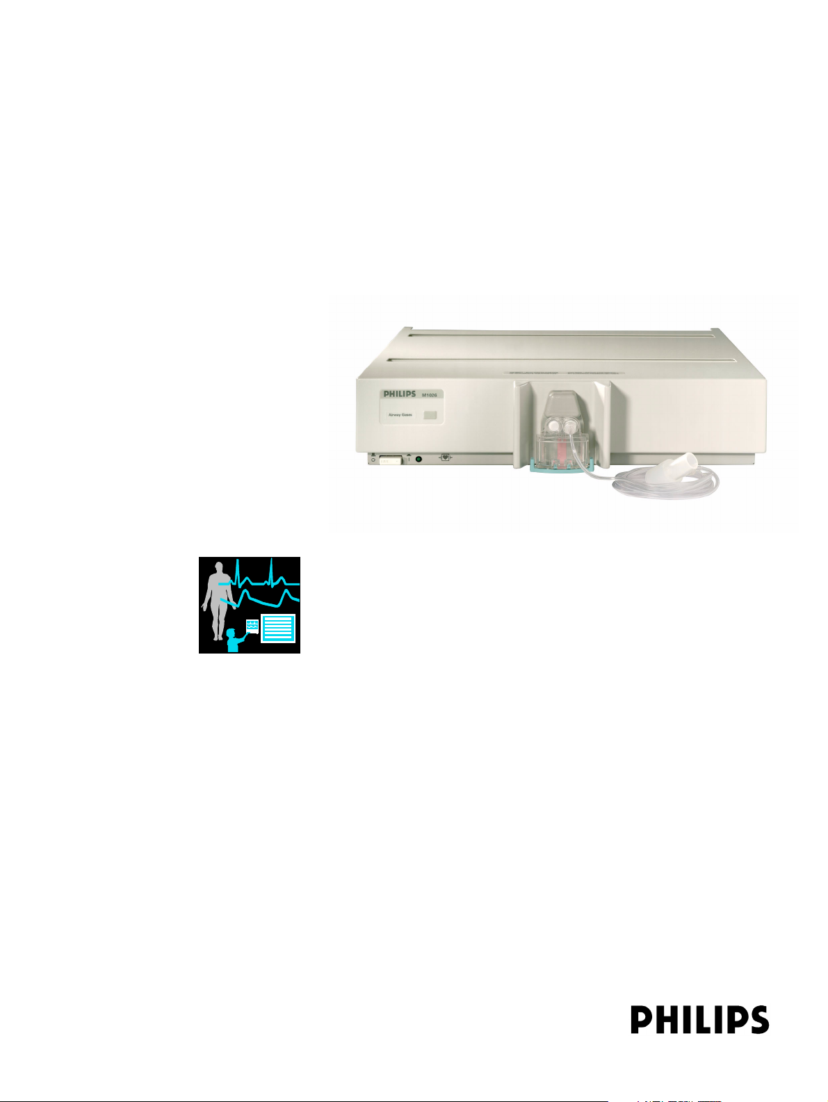
M1026B Anesthetic Gas Module
Service Guide
Anesthetic Gas Module
M1026B
Patient Monitoring
Page 2

Part Number M1026-9020A
Reordering Number: 453563499691
*M1026-9020A*
S PHI
Page 3

1Table of Contents
1 Introduction 7
Description 7
Physical Specifications 7
Environmental Specifications 8
Performance Specifications 8
CO2 Measurement 8
AWR R d eri ved fro m C O2 Wav ef o rm 9
N2O Measurement 9
O2 Measurement 9
Anesthetic Agent Measurement 9
Alarm Ranges 9
Alarm Delay 10
Apnea Alarm 10
INOP Alarms 10
General Measurement Principles 11
Theory of Operation 11
Main PC Board 12
Power Supply 12
Pneumatic System 12
Pump 13
Water trap 14
Sample Flow Through the Pneumatic Path 14
O2 Sensor 15
Specifications 15
Measurement Principle 15
The DIR Head Assembly 17
2 Installation and Patient Safety 19
Physical Installation 19
Environment 19
Making Connections to the AGM 20
Connections to the Sample Gas Exhaust 21
Returning the Gas Sample 21
Setting Up the Gas Return 21
Removing the Gas Sample 22
Setup and Configuration Procedures 22
Altitude Configuration 22
Connect Sample Input Tubing 23
Post-Installation Checks 23
3
Page 4

Safety Requirements Compliance and Considerations 23
Explanation of Symbols Used 23
Power Supply Requirements 24
Grounding the System 24
Equipotential Grounding 24
Combining Equipment 25
3 Checking and Calibrating the Anesthetic Gas Module 27
Access Service Functions of the M1026B Anesthetic Gas Module 27
When and how to check the Philips M1026B Anesthetic Gas Module 27
Equipment required for checking 28
Checks and adjustments 28
Pneumatic Check 28
Leak Check 31
Zero Calibration 34
Span Check 36
Disposal of Empty Gas Cylinder 40
Flowrate Check 41
Total Flowrate Check 41
Flow Calibration 42
4 Maintaining the Anesthetic Gas Module 47
Preventive Maintenance (PM) Tasks 47
Cleaning 48
Replace PM Parts 48
Replacing the Pump Oulet Filter and the Bacterial Filters 48
Replacing the Fan Filter 49
Replacing the Watertrap Manifold Seals 49
Test and Inspection Matrix 51
When to Perform Test Blocks 53
Safety Tests 53
5 Troubleshooting the Anesthetic Gas Module 57
INOPs 58
Troubleshooting 60
Troubleshooting Table: 61
6 Repairing the Anesthetic Gas Module 63
Introduction 63
Event Log 64
Removing the Top Cover 64
Replacing the Power Supply 68
Replacing the O2 Cell 70
Replacing the Pneumatic Assembly 71
4
Page 5

7 Parts List 75
Service Equipment 77
5
Page 6

6
Page 7

This chapter contains the following information on the M1026B Anesthetic Gas Module:
• A description of the Module, including its physical, environmental and performance specifications
• A general explanation of the measurement principles that the Module uses to measure gas
concentrations
• The theory of operation of the Module, its components and how they work.
Description
The Philips M1026B Anesthetic Gas Module works together with the IntelliVue MP40/50/60/70/90
and the ACMS and V24/26 patient monitors through an RS232 serial interface. It measures the airway
gases of ventilated patients who are under general gas anesthesia, or emerging from it.
1
1Introduction
The module produces graphical wave data, and inspired and end-tidal numeric data for the following
gases:
•CO
•N
• One volatile anesthetic agent
•O
It also generates a numeric for the patient’s airway respiration rate (AWRR).
The Agent Identification feature identifies which anesthetic agent is being used.
2
O
2
2
Physical Specifications
Size (H x W x D):
Weig ht: 6.3 kg (13.9 lb)
90mm x 370mm x 467mm (3.54 x 14.6 x 18.4 in)
7
Page 8

1Introduction Environmental Specifications
Environmental Specifications
Operating Temperature: 10 to 40°C (50 to 104°F)
Storage Temperature: -20 to 70°C (-4 to 158°F)
Humidity Limit (Operating): up to 95% RH max @ 40 °C (104 °F).
non-condensing
Humidity Limit (Storage): up to 95% RH max @ 70°C (158 °F).
non-condensing
Altitude Range (Operating): -381 to 3048m (-1,250 to 10,000 ft)
Altitude Range (Storage): -305 to 5,486m (-1,000 to 18,000 ft)
Warm-up Time: Full Accuracy after selftest is finished (max. 2 min)
Performance Specifications
All Performance and accuracy specifications are valid based on gas sample tubing M1658A, including
watertrap M1657B, and airway adapter 13902A.
Humidity Correction: For CO
Wet: p [mmHg] = c [Vol%] * (p_abs - p_H
Dry: p [mmHg] = c [Vol%] * p_abs /100
Where p = partial pressure, c = gas concentration, p_abs = pressure in breathing circuit, p_H
mmHg, partial pressure of water vapor of exhaled gas (37
For all other gases the readings are always given as dry values.
Sample Flow Rate: 150 ml/min.
Sample Delay Time: All measurements and alarms are subject to a delay of 3 seconds.
Total System Response Time = the sum of the delay time and the rise time.
CO2 Measurement
Range: 0 to 76 mmHg
Accuracy: ± 1.5 mmHg (0 - 30 mmHg)
Resolution: 1 mmHg
Rise-time: 410 msec typical
the humidity correction can be set to “wet” or “dry”.
2
O)/100
2
o
C, 100% rh).
± 5 rel. % (30 - 76 mmHg)
O = 47
2
The total system response time is the sum of the sample delay time (3 seconds) and the rise time (410
msec typical)
8
Page 9

Performance Specifications 1Introduction
AWRR derived from CO2 Waveform
Range: 0 to 60 rpm
Accuracy: ± 2 rpm
Resolution: 1 rpm
Detection Criteria: 6 mmHg variation in CO
N
O Measurement
2
Range: 0 to 85 vol%
Accuracy: ± 1.5 vol% + 5% relative
Resolution: 1 vol%
Rise-time: 510 msec typical
O
Measurement
2
Range: 0 to 100vol%
Accuracy: ± 3 vol%
Resolution: 1 vol%
Rise-time: 640 msec typical
Anesthetic Agent Measurement
2
Agent Range (vol%) Accuracy Resolution Rise Time
Halothane 0 - 7.5 ± (0.1 vol% + 4.0% relative) 0.05 < 900
Enflurane 0 - 7.5 ± (0.1 vol% + 4.0% relative) 0.05 < 620
Isoflurane 0 - 7.5 ± (0.1 vol% + 4.0% relative) 0.05 < 610
Sevoflurane 0 - 9.0 ± (0.1 vol% + 4.0% relative) 0.05 < 570
Desflurane 0 - 20.0 ± (0 . 1 v o l % + 4 . 0 % r e l a t i v e 0 . 0 5 ( 0 - 1 0 )
Alarm Ranges
AWRR 10 - 60 rpm 0 - 59 rpm
ETCO
0.1 (10.1-20)
Agent High Range Low Range
2
20 - 76 mmHg 10 - 75 mmHg
< 540
9
Page 10
1Introduction Performance Specifications
Agent High Range Low Range
IMCO
inN2O0 - 82 vol% none
inO
2
et SEV 0.1 - 9.0 vol% 0.0 - 8.9 vol%
in SEV 0.1 - 9.0 vol% 0.0 - 8.9 vol%
et DES 0.2 - 20.0 vol% 0.0 - 19.8 vol%
in DES 0.2 - 20.0 vol% 0.0 - 19.8 vol%
Halothane, Enflurane, Isoflurane
et 0.1 - 7.5 vol% 0.0 - 7.4 vol%
in 0.1 - 7.5 vol% 0.0 - 7.4 vol%
Alarm Delay
10 seconds if no automatic zero calibration occurs within that time.
Apnea Alarm
Delay Range: 10 - 40 seconds
Criterion No detected breath within the adjusted delay time
2
2 - 20 mmHg none
19-100 vol% 18 - 99 vol%
Alarm: Within 2 seconds after this criterion is met, if no automatic zero
INOP Alarms
INOP alarms are triggered if:
• The Philips M1026B Anesthetic Gas Module is disconnected or switched off.
• The equipment malfunctions.
• Zero calibration has failed.
• Zero calibration is in progress.
• The gas sample tube is occluded, or the water trap is full.
• The Philips M1026B Anesthetic Gas Module is unable to measure.
• Gas contaminant is detected.
• Agent mixture detected.
• Anesthetic agent detected but not selected.
• The module is in self-test.
• No breath detected.
occurs
10
Page 11
General Measurement Principles 1Introduction
General Measurement Principles
The M1026B Anesthetic Gas Module uses a technique called Dispersive Infrared (DIR) absorption to
measure the concentration of certain gases. The gases measured by the M1026B Anesthetic Gas
Module (except oxygen) absorb infrared (IR) light and each gas has its own absorption characteristic.
The gas is transported into a sample cell. A diffraction grating is used to scan the relevant wavelength
range of the IR light that passes through the sample cell. The higher the concentration of gas the more
IR light is absorbed, and from the amount of IR light measured, the concentration of gas present can
be calculated.
Individual gases have an individual spectral fingerprint. A mathematical algorithm is used to analyze
the spectrum and to identify and quantify the anesthetic agents in the gas.
Oxygen is measured by an additional sensor in the M1026B Anesthetic Gas Module using its
paramagnetic properties.
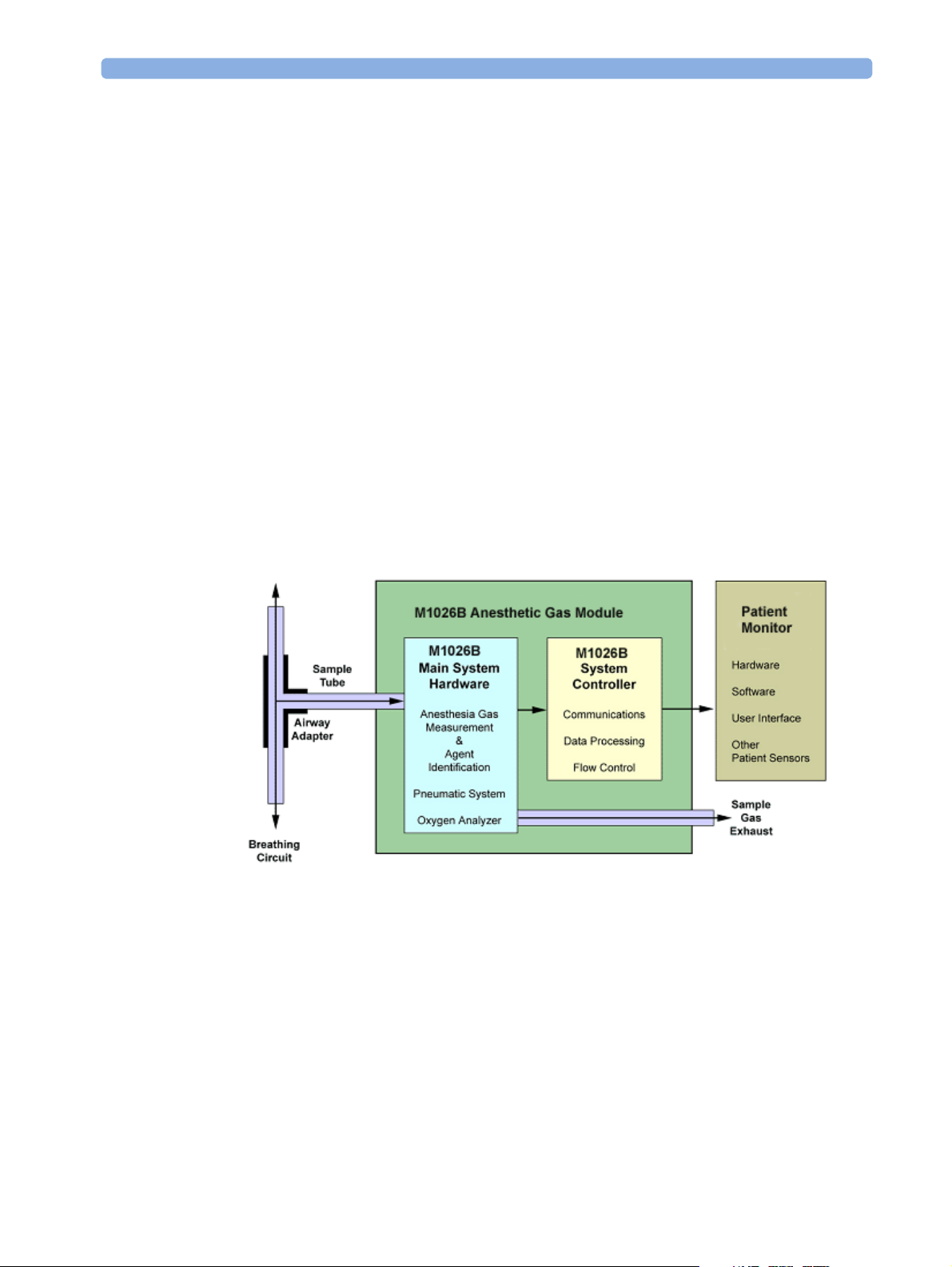
Theory of Operation
Figure 1 shows the functional blocks within the Philips M1026B Anesthetic Gas Module.
Figure 1 Anesthetic Gas Module Functional Block Diagram
The main components of the Philips M1026B Anesthetic Gas Module are:
• Main PC Board.
• Power Supply.
•Pneumatic Assembly.
Sensor.
•O
2
11
Page 12

1Introduction Theory of Operation
• DIR optics.
Main PC Board
The electronics subsystem, with memory (FLASH & RAM), multiplexers, A-D converter, and power
line supervision, is responsible for the following functions:
• The acquisition and processing of data from, and control of, the anesthesia gas measurement
analyzer.
• The acquisition and processing of data from the oxygen analyzer.
• Controlling the pneumatic system.
• Controlling the communications between the M1026B and the host monitoring system.
The M1026B electronics subsystem has one communications channel, connected to an external RS232
port.
The M1026B functionality is controlled by Flash Memory resident software.
Power Supply
The input voltage is 100V - 240V. The output voltages are ±12V and +3.3V.
Pneumatic System
The main parts of the pneumatic system are:
• Watertrap.
• Pneumatics assembly including:
– pump outlet filter
– two flow restrictors
– four bacterial filters
– three solenoid valves
– dampening volumes
•Pump
12
Page 13
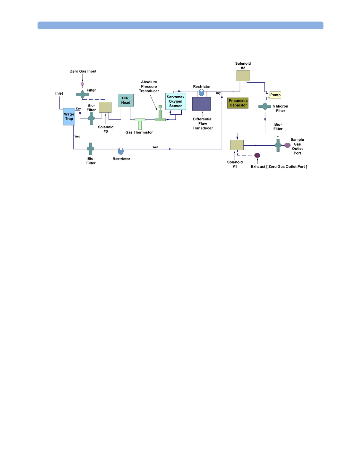
Theory of Operation 1Introduction
Figure 2 Pneumatic System
Pump
The pneumatic system works in the following way:
1 Eliminates residual water and fluids from patient sample gas using the watertrap.
2 Splits the patient’s sample gas flow (150ml/min) into the measurement path (120ml/min) and
drainage path (30ml/min).
3 Passes the patient’s sample gas in the measurement path at 120ml/min through the measurement
bench (O2 analyzer, DIR Head).
4 Delivers zero calibration gas to the sample cells for the periodic zeroing.
5 Exhausts the patient’s sample gas, the zero calibration gas, and the span calibration gas.
6 Monitors for an occlusion in the sampling pneumatics.
The software-controlled pump generates the flow through the system and pulls the gas from the airway
adapter through the measurement subsystems to the exhaust outlet. It also delivers the zero calibration
gas to the sample cells of the measurement subsystems for the periodic zero procedures and it exhausts
the patient’s sample gas, the zero calibration and field calibration gases.
The flow-rate control logic drives the pump as hard as necessary to maintain the selected flow rate. A
partial occlusion or an inefficient pump results in the pump being driven harder. A serious occlusion
results in the pump being driven at or near its maximum load. This triggers a logic, which then reports
an occlusion.
13
Page 14
1Introduction Theory of Operation
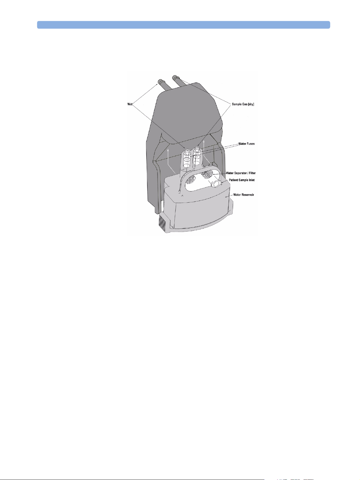
Watertrap
Figure 3 Watertrap
The watertrap consists of two water separation filters, two water fuses and a water reservoir. The gas
sample coming from the patient may contain fluids which are separated from the gas at the first water
separation filter. The gas is then split into two paths, the “measurement” path with the main part of the
total gas flow (including water vapor) continuing on the “dry” side of the separation filter and the
“drainage” path (containing any liquid droplets) with the smaller amount of the total flow continuing
on the “wet” side of this filter through the water reservoir. At the pump both gas paths are recombined.
The watertrap proper includes “water fuses” in both the “measurement” and the “drainage” paths,
consisting of a material that swells when getting wet (when the reservoir is full or when fluid penetrates
the separation filter and enters the “measurement” path) and blocks the respective path at the inlet of
the unit. Once the “water fuses” are blown, any passage of fluid is blocked and the gas flow resistance
increases so that an occlusion is detected.
Sample Flow Through the Pneumatic Path
The drainage path serves to withdraw fluid separated at the first water separation filter from the gas
sample into the watertrap reservoir.The drainage path leads into the large watertrap reservoir where all
liquid water and other fluids are collected. When the drainage path leaves the watertrap through a
water separation filter and a through a water fuse it leads through a bacterial protection filter and flow
restrictor directly to the pump. This flow restrictor determines the percentage distribution between
drainage and measurement path flow.
14
Page 15

Theory of Operation 1Introduction
The measurement path leads through the first water separation filter and through a water fuse on into
the measurement system. The patient sample gas (on the measurement path) then flows through a
bacterial protection filter to solenoid valve #0. Room air for the zero calibration is alternatively input
(via a filter) to this solenoid valve. The solenoid valve switches between the two gases depending on the
current mode of operation - normal measurement or zero calibration.
The patient sample gas or zero calibration gas then flows through the measurement subassemblies:
– the DIR Measurement Assembly (for measurement of anesthetic agent, CO
–the O
From here it is passed to the flow sensor which consists of a differential pressure transducer and a flow
restrictor. The flow sensor determines, stabilizes and limits the flow rate of the sampled gas.
Then the patient sample gas or zero calibration gas flows to the pump. Before reaching solenoid valve
#2 and the pump, it joins the drainage path again.
After the gas has passed through solenoid valve #1 it is routed through a filter to the Sample Gas
output. Alternatively, the zero gas is output to the zero gas outlet port by this solenoid valve.
2
cell
O2 Sensor
Specifications
Weight 150 g
Size (HxWxD) 65 x 30 x 65 mm
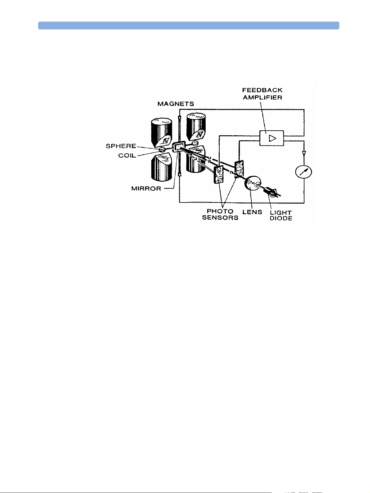
Measurement Principle
The O2 sensor uses a fast O2 measurement technique that utilizes O2 paramagnetic properties.
and N2O)
2
Two sealed spheres are filled with N
mirror is mounted centrally on the suspension and light is shone onto the mirror. The reflected light is
directed onto a pair of photocells. Oxygen attracted into the magnetic field displaces the nitrogen filled
spheres, causing the suspension to rotate. The photocells detect the movement and generate a signal.
and mounted on a rotating suspension within a magnetic field. A
2
15
Page 16
1Introduction Theory of Operation
The signal generated by the photocells is passed to a feedback system which passes a current around a
wire mounted on the suspension. This causes a motor effect which keeps the suspension in its original
position. The current flowing around the wire is directly proportional to the concentration of oxygen
within the gas mixture.
16
Page 17
Theory of Operation 1Introduction
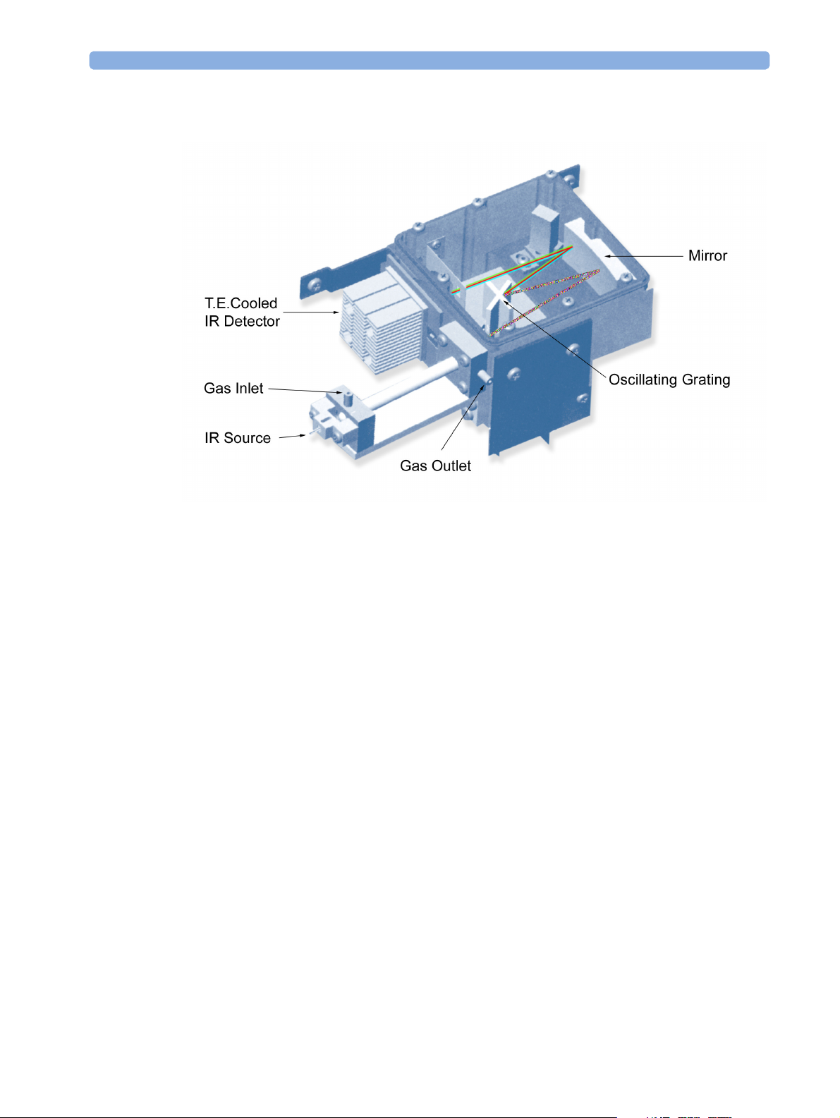
The DIR Head Assembly
Figure 4 Anesthetic Gas Module DIR Head Assembly
The DIR head functions as follows:
The infrared light source is a tungsten filament lamp.
The Anesthetic Gas Module sample cell is constructed of a glass tube with a highly reflective gold
coated internal surface that serves as a light pipe. The sample cell length is designed to provide an
adequate absorption length to obtain the desired signal-to-noise ratio for the weakest anticipated
absorption. Sapphire serves as the sample cell window material for the two ends of the sample cell.
The gas sample to be analyzed enters the sample cell through the gas inlet and leaves it through the gas
outlet. While in the cell, the gas sample is penetrated by light from the infrared light (IR) source. This
light is dispersed via a single diffraction grating. The attached brushless DC rotary actuator working in
tune with an encoding mechanism ensures that the grating is always in the correct position. The
dispersed light is reflected by a mirror and lastly hits a dual filter/detector package.
Software then takes the data from the scan of the dispersed component wavelengths to produce a
characteristic curve, its shape determined by the relative concentrations of different gases in the sample.
A thermistor in the outlet gas stream measures the sample gas temperature. A transducer measures
sample gas pressure. Knowledge of sample gas pressure and sample gas temperature is vital for accurate
gas measurements.
Zero calibration capability is provided to maintain long-term, stable gas concentration measurement.
17
Page 18

1Introduction Theory of Operation
18
Page 19

2Installation and Patient Safety
This chapter describes how to install the Philips M1026B Anesthetic Gas Module. It details the
operating environment required by the Philips M1026B Anesthetic Gas Module as well as instructions
on how to affix the local language labels and physically connect it to the monitor. Next, the patient
safety information is detailed. Finally, this chapter describes the software setup required and any postinstallation checks that have to be performed before using the Philips M1026B Anesthetic Gas Module
together with a reminder of the preventive maintenance (PM) checks and their frequencies.
Physical Installation
This section describes the operating and storage environment for the Philips M1026B Anesthetic Gas
Module, affixing the local-language labels, connecting to the monitor, and fitting the gas exhaust
return system.
2
CAUTION The Philips M1026B Anesthetic Gas Module must be positioned horizontally on a level surface. To
avoid condensed water collecting in the patient sample tube, it is recommended that the Philips
M1026B Anesthetic Gas Module is positioned at or above patient level, wherever possible.
Environment
WARNING Possible explosion hazard if used in the presence of flammable anesthetics.
The environment where the Philips M1026B Anesthetic Gas Module is used should be free from
vibration, dust, corrosive or explosive gases, and extremes of temperature and humidity.
For a cabinet mounted installation with the monitor, allow sufficient room at the front for operation
and sufficient room at the rear for servicing with the cabinet access door open.
The Philips M1026B Anesthetic Gas Module operates within specifications at ambient temperatures
between 15°C and 40°C, 2 minutes after switching it on.
Ambient temperatures that exceed these limits could affect the accuracy of this instrument and cause
damage to the components and circuits. Allow at least 2 inches (5cm) clearance around the instruments
for proper air circulation.
CAUTION If the Philips M1026B Anesthetic Gas Module has been stored at temperatures below freezing, it needs
a minimum of 4 hours at room temperature to warm up before any connections are made to it.
19
Page 20
2 Installation and Patient Safety Making Connections to the AGM
Make sure that the Philips M1026B Anesthetic Gas Module is free of condensation before operation.
Condensation can form when equipment is moved from one building to another, thus being exposed
to moisture and differences in temperature.
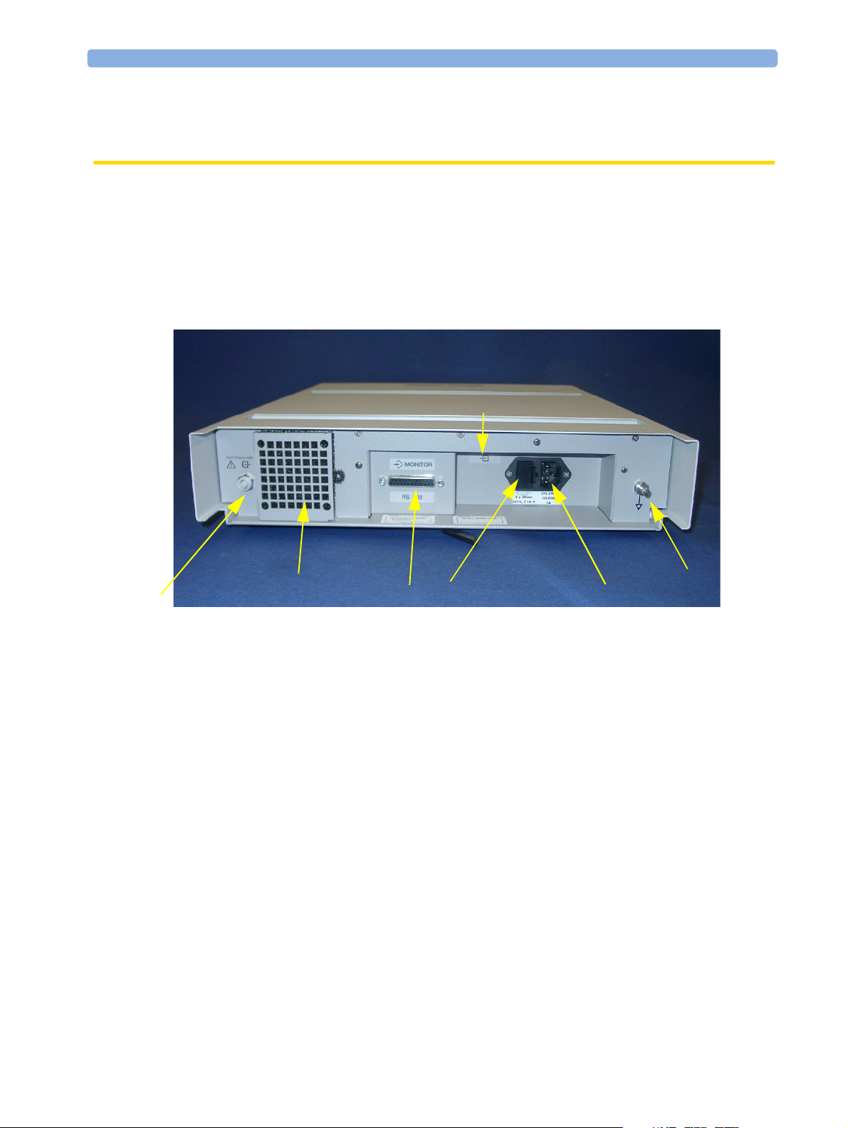
Making Connections to the AGM
All connections to the AGM are made on its rear panel. Refer to Figure 5.
6
5
Figure 5 The Rear Panel
1 Local power connector; this is a 3-pin connector, used to connect the AGM to the local line voltage
supply.
The Anesthetic Gas Module can be operated from an ac power source of 100 - 240 V ± 10%, 50/60
Hz. The adjustment is made automatically by the power supply inside the module.
2 RS232 Connector (RS232 Interface); this is a 25-pin “D” type connector, used to connect the
AGM to the monitor.
The connection to an IntelliVue patient monitor can be made with the following cables:
– M1026B#K11 1 m (M1026-61001)
– M1026B#K12 3 m (M1026-61002)
– M1026-61003 10 m
The connection to an ACMS patient monitor can be made with the following cables:
– M1181A#A52 or M1026B#K01 1 m (M1181-61658)
– M1181A#A51 3 m (M1181-61632)
– M1181A#A5A 10 m (M1181-61630)
The connection to a V24/V26 patient monitor can be made with the following cable:
– M1204-60192 (1.2 m)
7
2
4
1
3
20
Page 21

Connections to the Sample Gas Exhaust 2 Installation and Patient Safety
3
Equipotential Grounding Terminal; this is used to connect the AGM to the hospital’s grounding
system.
4 Line protection fuses, T1 A H 250V.
5 Anesthetic gas exhaust. If N
pollution of the operating room should be prevented. Once the gas sample has passed through the
AGM, it should either be returned to or removed from the anesthesia circuit.
6 Zero Gas Exhaust
7 Fan Filter
O and/or other inhalation anesthetics are used during anesthesia,
2
Connections to the Sample Gas Exhaust
Returning the Gas Sample
You will need the following equipment to return the gas sample to the anesthesia circuit:
Equipment Part Number Comments
Gas Exhaust Return Line M1655A Tub in g i n c l ud e s t w o pa r t s :
Tube A = 50cm long
Tube B = 3m long
Gas Exhaust Return Filter M1656A Single patient use only
NOTE The M1655A may not be available in all countries.
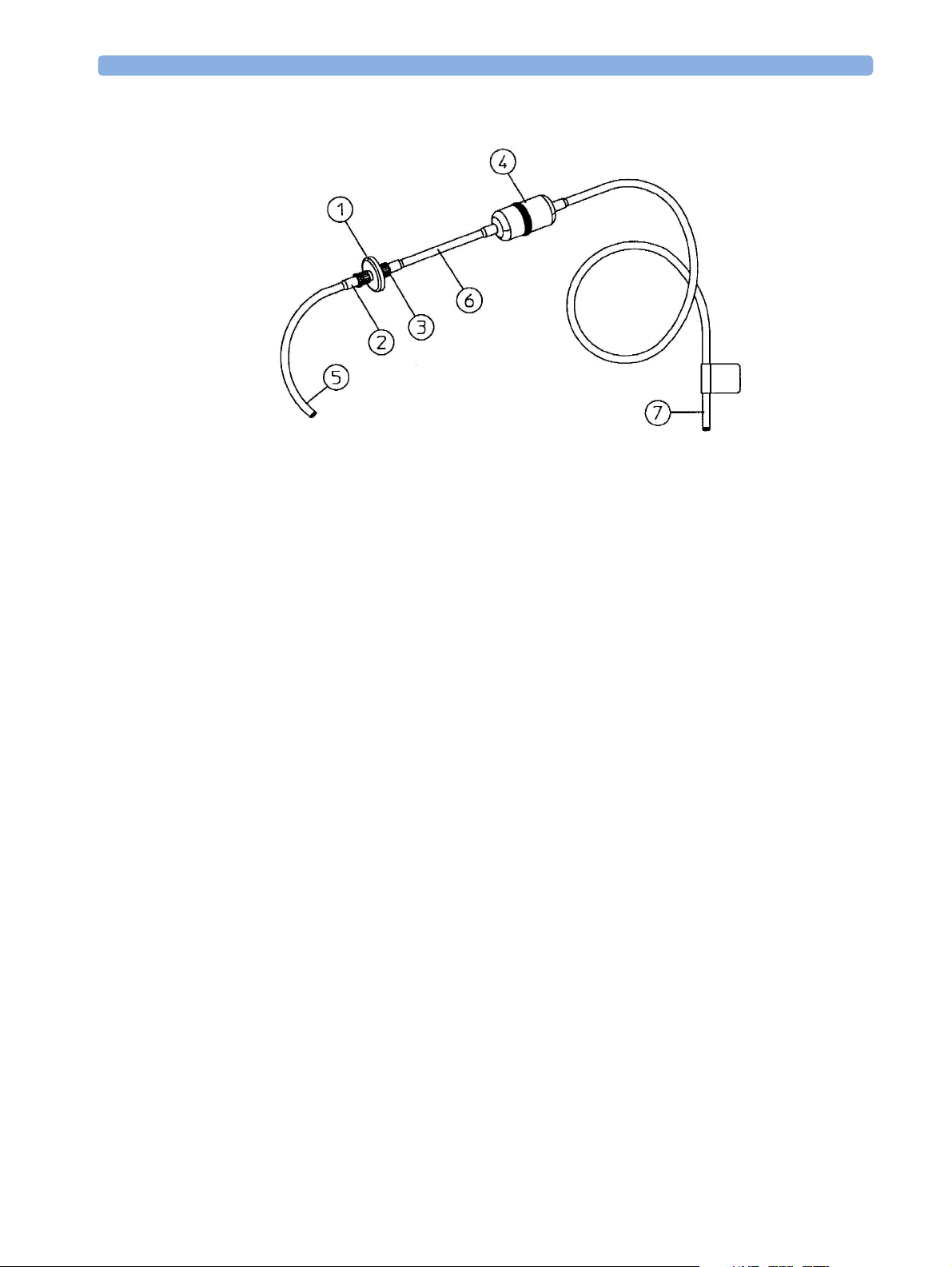
Setting Up the Gas Return
(see diagram Figure 6)
1 Fit the male luer lock connection (2) of the shorter tube, to the female side of the M1656A Gas
Exhaust Return Filter.
2 Fit the female luer lock connection (3) of the longer tube, to the male side of the M1656A Gas
Exhaust Return Filter.
3 Fit the open end (7) of the longer tube to the AGM’s Anesthetic Gas Exhaust.
4 Fit the open end (5) of the shorter tube to the ventilation circuit.
21
Page 22
2 Installation and Patient Safety Setup and Configuration Procedures
Figure 6 Setting Up the M1655A Gas Exhaust Return Line
1 M1656A Gas Exhaust Return Filter
2 Female luer lock
3 Male luer lock
4 Dampener
5 Shorter tube
6 Connecting tube
7 Longer tube - connected to AGM exhaust port
Removing the Gas Sample
To remove the gas sample from the anesthesia circuit, a scavenging system needs to be connected to the
AGM’s Anesthetic Gas Exhaust. If you intend to use a scavenging system with the AGM, one of the
following parts must also be connected to protect it against malfunction:
1 A ventilator reservoir where the suction pressure does not exceed 0.3-0.4 mmHg or
2 A scavenging interface, properly set and maintained (see scavenging interface manufacturer’s
instructions).
Setup and Configuration Procedures
This section describes final setting up and configuration procedures that must be completed after the
AGM is connected to the monitor and switched on before the AGM is used for monitoring.
Altitude Configuration
The altitude setting for the monitor is important as it is used as a reference to check the AGM ambient
pressure measurement.
22
Page 23
Post-Installation Checks 2 Installation and Patient Safety
See your monitor service guide for details.
Connect Sample Input Tubing
Connect the sample input tubing to the watertrap at the luer lock connector. For details, refer to the
Instructions for Use.
Post-Installation Checks
See Test and Inspection Matrix for details.
WARNING Do not use the instrument for any monitoring procedure on a patient if you identify anything which
indicates impaired functioning of the instrument.
Safety Requirements Compliance and Considerations
The Philips M1026B Anesthetic Gas Module complies with the following international safety
requirements for medical electrical equipment:
• UL 2601-1
• IEC-60601-1
• CSA C22.2 No. 601.1-M90
• EN 60601-1
• EN 60601-1-2
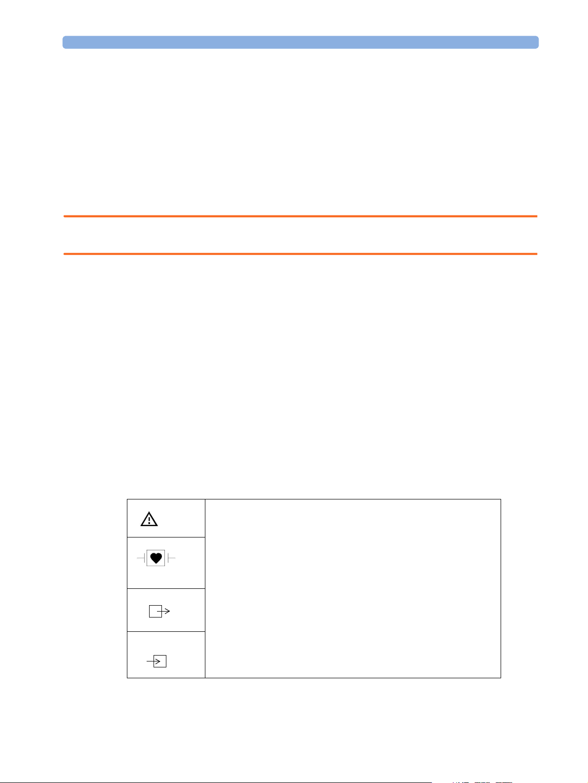
Explanation of Symbols Used
Attention, consult accompanying documents.
Indicates that the instrument is type CF and is designed to have special
protection against electric shocks (particularly regarding allowable leakage
currents, having an F-Type isolated (Floating) applied part), and is
defibrillator proof.
A gas output.
A gas input.
23
Page 24
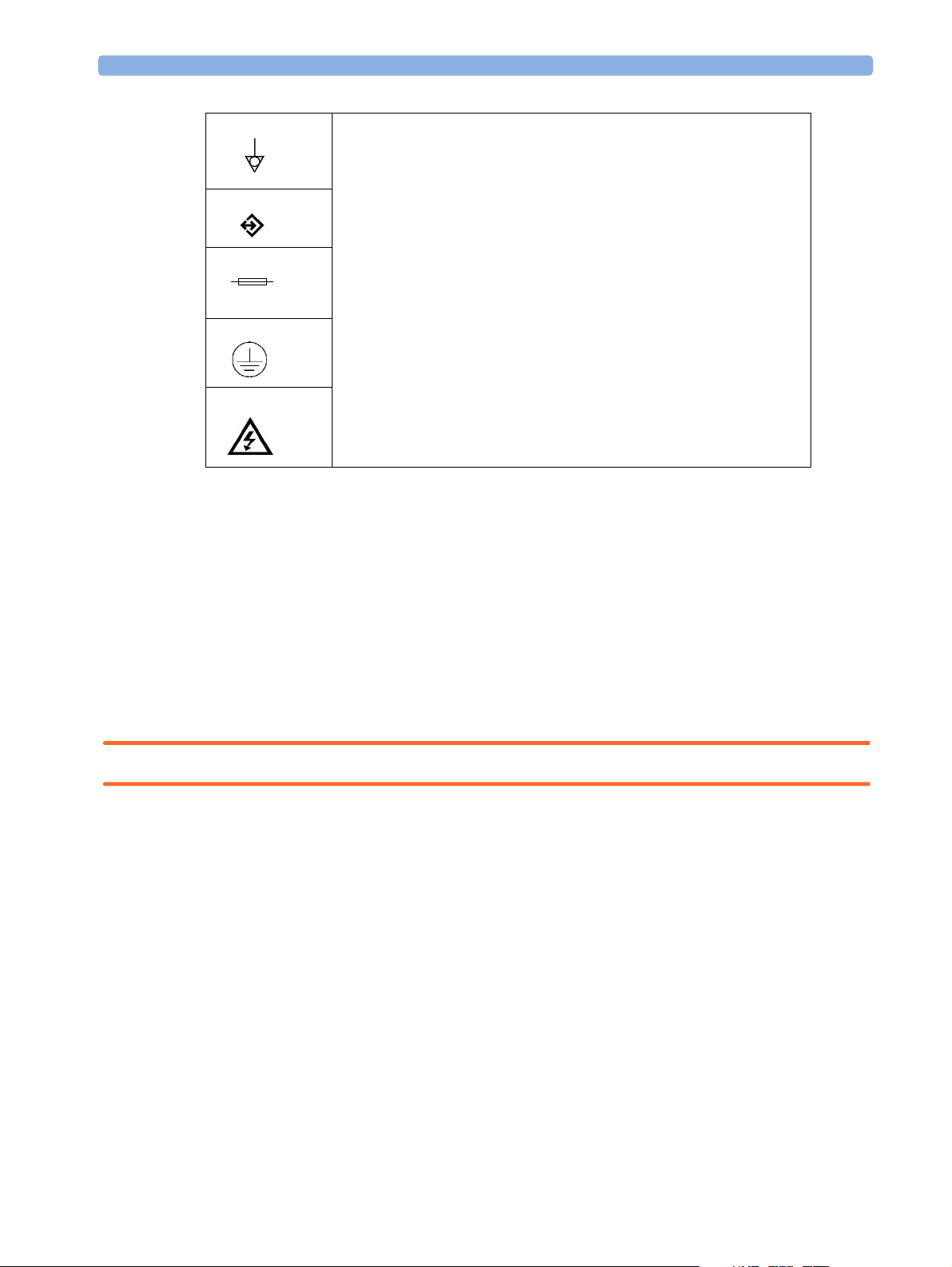
2 Installation and Patient Safety Safety Requirements Compliance and Considerations
Equipotential grounding terminal.
RS232 communication port.
Fuse.
Protective earth ground.
Electrical shock hazard.
The Anesthetic Gas Module is protected against the effects of defibrillation and electrosurgery.
Power Supply Requirements
The system and the Anesthetic Gas Module can both be operated from an AC supply of 100 - 240V
±10%, 50 - 60Hz.
Grounding the System
To protect the patient and hospital personnel, the cabinet of the installed equipment has to be
grounded. The equipment is supplied with a detachable 3-wire cable which grounds the instrument to
the power line ground (protective earth) when plugged into an appropriate 3-wire receptacle. If a 3wire receptacle is not available, consult the hospital electrician.
WARNING Do not use a 3-wire to 2-wire adapter.
Equipotential Grounding
Protection class 1 instruments are already included in the protective grounding (protective earth)
system of the room by way of grounding contacts in the power plug. For internal examinations on the
heart or the brain, Computer Module and Display Module of the System and the Philips M1026B
Anesthetic Gas Module must have separate connections to the equipotential grounding system.
One end of the equipotential grounding cable (potential equalization conductor) is connected to the
equipotential grounding terminal on the instrument’s rear panel and the other end to one point of the
equipotential grounding system. The equipotential grounding system assumes the safety function of
the protective grounding conductor if ever there is a break in the protective grounding system.
24
Examinations in or on the heart (or brain) should only be carried out in rooms designed for medical
use incorporating an equipotential grounding system.
Page 25

Safety Requirements Compliance and Considerations 2 Installation and Patient Safety
Combining Equipment
If it is not evident from the instrument specifications whether a particular instrument combination is
hazardous or not, for example, due to summation of leakage currents, the user should consult the
manufacturers concerned or an expert in the field, to ensure that the necessary safety of all instruments
concerned will not be impaired by the proposed combination.
25
Page 26

2 Installation and Patient Safety Safety Requirements Compliance and Considerations
26
Page 27

3
3Checking and Calibrating the
Anesthetic Gas Module
This chapter explains how to check the Anesthetic Gas Module to ensure that it is operating within its
specified limits. A list of the equipment required to carry out the checks is included, as well as step-by
step instructions for the calibrations.
If you receive fail indications while testing, refer to the troubleshooting section of this document for
guidance. If you are instructed to remove or replace parts of the Anesthetic Gas Module refer to the
respective section.
Access Service Functions of the M1026B Anesthetic Gas Module
Service functions of the M1026B Anesthetic Gas module are accessed with the M1026B Service
Software which is available on the Service Guide CD shipped with the product.
When and how to check the Philips M1026B Anesthetic Gas Module
To ensure that the Philips M1026B Anesthetic Gas Module operates with the specified limits, it must
be checked:
1 Every 12 months or if the measurements are in doubt.
2 After repairing the AGM
If you find values outside the tolerance limits while checking, the Philips M1026B Anesthetic Gas
Module must be repaired.
The basic steps to check the Philips M1026B Anesthetic Gas Module are:
1 Connect a PC/Laptop running the M1026B Service Software to the Anesthetic Gas Module and
wait for the first zero calibration after the startup period.
2 Perform:
a. a leakage check
b. a flowrate check
to ensure that there are no leaks in the gas system and that the flowrates are set correctly.
3 Perform Zero calibration.
27
Page 28

3 Checking and Calibrating the Anesthetic Gas Module Equipment required for checking
4 Check that there are no reported errors.
5 Check the Span calibration of gases.
WARNING Only perform Zero and Span calibration checks when the top cover is closed. Light and electro-
magnetic interference can affect the measurements.
Equipment required for checking
The following equipment is required for checking the AGM. Part numbers are given in the Parts List
section.
1 Electronic Flowmeter M1026-60144 (Instructions are provided with the flowmeter. See also
Service Note M1026A-034).
2 Span Check Equipment.
– Check Gas (M1662A).
– Calibration Tubing (M1659A).
– Luer lock plug available on the elbow airway adapter (13902A).
3 Flow Split Test Fixture (M1026-60136)
Checks and adjustments
The following sections explain the steps needed to carry out the checks and adjustments. A complete
check and calibration procedure requires approximately 30 minutes, including waiting time.
NOTE Make sure that the watertrap is attached.
Pneumatic Check
Always perform a pneumatic check before performing a leak check or before retrieving a temperature
or ambient air pressure reading.
28
Page 29

Pneumatic Check 3 Checking and Calibrating the Anesthetic Gas Module
1
Select Pneumatic Check from the Checks pull-down menu.
29
Page 30

3 Checking and Calibrating the Anesthetic Gas Module Pneumatic Check
2
Click on Send.
30
Page 31

Leak Check 3 Checking and Calibrating the Anesthetic Gas Module
3
Wait for the “passed” message.
Leak Check
Complete the following steps to do a leak check:
NOTE Do not perform the leak check while a Zero calibration is running.
31
Page 32

3 Checking and Calibrating the Anesthetic Gas Module Leak Check
1
Select Leak Check from the Checks pull down menu.
32
2 Block the watertrap inlet using for example the cap of the airway adapter.
Page 33

Leak Check 3 Checking and Calibrating the Anesthetic Gas Module
3
Click Send in the Leak Check window.
4 While the leak check is running, the Process State field will read In Process.
5 Wait until the Process State field goes blank again, indicating that the check is finished. Then
remove the blockage from the watertrap inlet.
33
Page 34

3 Checking and Calibrating the Anesthetic Gas Module Zero Calibration
6
Check whether the leak check reports pass or fail. If the leak check fails make sure all internal
tubing connections are tight.
Zero Calibration
NOTE Only perform a zero calibration with the top cover closed. Light and electro-magnetic interference may
affect the measurements. Zero calibration is not possible during warm-up.
34
Page 35

Zero Calibration 3 Checking and Calibrating the Anesthetic Gas Module
A zero calibration will be performed automatically when required if Auto Zero is selected in the Service
Tool main screen.
If Auto Zero is not selected the Zero Requested field will read Yes everytime a zero calibration is
required. To perform a zero calibration manually:
35
Page 36

3 Checking and Calibrating the Anesthetic Gas Module Span Check
1
Click Zero in the Service Tool main screen.
Span Check
NOTE The Philips M1026B Anesthetic Gas Module should run for 2 minutes until the operating mode in the
service tool reads Normal before continuing with the following calibration procedures. This is to allow
the module to reach a stable measurement condition.
Only perform Span checks when the top cover is closed. Light and electro-magnetic interference can
affect the measurements.
Before performing a Span check, you must first:
• perform a Leak Check.
•perform a Zero Calibration.
• Ensure that there is enough gas in the check gas bottle.
• Check tubing assembly.
36
Page 37

Span Check 3 Checking and Calibrating the Anesthetic Gas Module
M1662A
Figure 7 Span Checking Equipment including Gas Canister and Spray Valve
CAUTION Ensure that the room you are working in is well-ventilated, and that the Philips M1026B Anesthetic
Gas Module exhaust is properly connected to the gas scavenging system.
37
Page 38

3 Checking and Calibrating the Anesthetic Gas Module Span Check
1
Select Span Check in the Checks pull down menu.
38
Page 39

Span Check 3 Checking and Calibrating the Anesthetic Gas Module
2 Select the agent you are checking and enter the corresponding gas values as given on the chck gas
bottle.
3 Connect the calibration gas bottle, the reservoir bag and the sample line as shown in Figure 7,
"Span Checking Equipment including Gas Canister and Spray Valve".
4 Wait until the Sample Delivery field in the Module Status section of the service software reads
Error, indicating taht the reservoir bag is empty. Now wait for another 10 seconds to let the
Anesthetic Gas Module completely evacuate the reservoir bag.
5 Now fill the reservoir bag with gas.
CAUTION Do not pressurize the reservoir bag.
Do not attempt the span check process if there are any visible leaks in the bag or tubing.
Prevent the bag from emtying before the span check procedure is complete.
6 Click Send in the Span Check window.
39
Page 40

3 Checking and Calibrating the Anesthetic Gas Module Span Check
7 Check whether the check has been passed.
8 If the check has not passed, check for any errors in the module status windows of the service
software and proceed to the troubleshooting section of this manual.
Disposal of Empty Gas Cylinder
1 Empty cylinder completely by pushing in the pin of the valve.
2 Once the cylinder is empty, drill a hole in the cylinder
CAUTION Be careful to assure that the cylinder is completely empty before you try to drill the cylinder.
40
Page 41

Flowrate Check 3 Checking and Calibrating the Anesthetic Gas Module
3
Write "Empty" on the cylinder and place it with your scrap metal or, if you do not collect scrap
metal for recycling, dispose of the cylinder.
Flowrate Check
1 Before starting a flowrate check, get an ambient pressure reading by:
a. performing a zero calibration
b. performing a pneumatic check to update temperature and pressure data
c. selecting the Temperature and Pressure Data from the Data pull down menu and
clicking on send.
The Ambient Pressue (mmHg) field in that window provides the ambient pressure that should be used
for correcting the electronic mass flowmeter reading.
2 Connect a flowmeter to the flow split test fixture.
3 Check the measurement path flowrate at low flow and high flow.
4 If you are using the electronic flowmeter M1026-60144, correct the reading for each step
according to the following formula:
or: in order to get the actual reading for a desired flowrate:
Flowrate in each mode
Low flow 96 ml/min +/- 5ml/min
High flow 160 ml/min +/- 8ml/min
If the flowrate is out of tolerance, perform a flow calibration.
Total Flowrate Check
1 Restart the M1026B Anestehtic Gas Module.
2 Connect the Anesthetic Gas Module to the patient monitor.
Flow Reading 760 mmHg×
---------------------------------------------------------------------
Actual Flow
Flow Reading Desired Flowrate
=
Actual Ambient Air Pressure
Actual Ambient Air Pressure
---------------------------------------------------------------------
×=
760 mmHg
To le r a nc e
3 Measure the total flowrate at the watertrap. It should be 150 +/- 15 ml/min. If it is out of tolerance,
troubleshoot the pneumatics assembly.
41
Page 42

3 Checking and Calibrating the Anesthetic Gas Module Flow Calibration
Flow Calibration
1 Before starting a flow calibration, get an ambient pressure reading by:
a. performing a zero calibration
b. selecting the Temperature and Pressure Data from the Data pull down menu and
clicking on send.
The Ambient Pressue (mmHg) field in that window provides the ambient pressure that should be
used for correcting the electronic mass flowmeter reading.
2 Select Calibrate Flow from the Calibration pull down menu.
42
Page 43

Flow Calibration 3 Checking and Calibrating the Anesthetic Gas Module
3
Connect the Flowmeter to the dry line of the flow split test fixture and then click Next Step.
4 If you are using the electronic flowmeter M1026-60144, correct the reading for each step
according to the following formula:
Flow Reading 760 mmHg×
Actual Flow
---------------------------------------------------------------------
=
Actual Ambient Air Pressure
or: in order to get the actual reading for a desired flowrate:
Actual Ambient Air Pressure
Flow Reading Desired Flowrate
---------------------------------------------------------------------
×=
760 mmHg
43
Page 44

3 Checking and Calibrating the Anesthetic Gas Module Flow Calibration
5
Calibrate:
- Low Flow,
- High Flow and
- Purge Flow
always following the instructions on the screen while making sure to correct the reading as
described in step 3 above.
Always click the Calibrate Low/High/Purge Flow button before proceeding with Next
Step and allow the instrument to stabilize before calibrating on a certain flowrate.
If the desired flowrate cannot be reached exactly, take the actual flow reading and (after coorecting it
for ambient air pressure influences if using the M1026-60144) enter this value into the field Flow
Value.
NOTE During the flow calibration procedure (especially at the purge flowrate) a Sample delivery error flag
and a yellow correctable error may appear on the main screen of the M1026B Service Software. These
should disappear after the calibration procedure is completed.
44
Page 45

Flow Calibration 3 Checking and Calibrating the Anesthetic Gas Module
6
Save the calibration and click Next Step to complete the flow calibration process.
45
Page 46

3 Checking and Calibrating the Anesthetic Gas Module Flow Calibration
46
Page 47

4Maintaining the Anesthetic
Gas Module
WARNING Failure to implement a satisfactory maintenance schedule by the individual, hospital or institution
responsible for the operation of this equipment may cause equipment failure and possible health
hazards.
This chapter describes the Preventive Maintenance tasks (PMs) required to keep the Philips M1026B
Anesthetic Gas Module in good working order. PMs are performed to a timetable before problems
arise as a means to reduce failures.
A test and inspection matrix which explains when and how to perform safety and performance tests is
included at the end of the chapter.
4
All checks that require the instrument to be opened must be made by qualified service personnel.
CAUTION Take precautions when dealing with potentially contaminated parts, such as tubing and other
components of the patient circuit. Wear gloves, mask and gown while handling components that come
into contact with the patient’s exhalant gas or fluids.
Preventive Maintenance (PM) Tasks
Here is a list of the PM tasks required to ensure satisfactory operation of the Philips M1026B
Anesthetic Gas Module within its specified limits and how often they must be performed.
• Check the fan filter for occlusions every 6months.
• Check the fan in the AGM for proper operation every 6months.
• Check the AGM’s accuracy at least once every 12 months, or whenever the validity of the readings is
in doubt. Refer to Checking and Calibrating the Anesthetic Gas Module for details.
• Replace the parts contained in the PM Kit every 24 months.
Check the pump hours during the replacement procedure. If the pump hours exceed 10000 hours,
replace the pneumatic assembly.
• Check electrical safety (ground impedance and enclosure leakage current test) at least every 12
months or every time the device is removed and reinstalled.
47
Page 48

4 Maintaining the Anesthetic Gas Module Cleaning
Cleaning
Each time the top cover is removed from the AGM for repair or calibration, you should take the
opportunity to clean the inside of the module, as the fan may draw debris such as dust and lint into the
enclosure.
WARNING Switch off the instrument and disconnect it from the mains power supply. Take standard electrostatic
precautions. For example, wrist strap connected to electrical ground.
The user should be encouraged to periodically clean the exterior casing of the AGM. The outside of the
gas sample tubing should be cleaned before connecting to the next patient.
Replace PM Parts
Every 24 months the PM parts should be replaced for new with the PM kit. The PM kit comprises:
• 4 bacterial filters
• 1 pump outlet filter
•2 fan filters
•pump tubing kit
• 2 watertrap manifold seals
Replacing the Pump Oulet Filter and the Bacterial Filters
1 Remove the tubing from the green pump outlet filter and replace the filter.
48
Page 49

Replace PM Parts 4 Maintaining the Anesthetic Gas Module
2
Remove the screws and brackets securing the four bacterial filters and replace the filters.
4th filter on the side
of the pneumatic
assembly
Replacing the Fan Filter
1 Pull out the fan filter to the right from the fan and replace it with a new one.
Replacing the Watertrap Manifold Seals
1 Remove the two screws holding the watertrap manifold on the protector. The screws are accessible
from the rear side of the front cover through two holes provided for this purpose.
49
Page 50

4 Maintaining the Anesthetic Gas Module Replace PM Parts
2
Pull out the two seals from the tubing connectors of the manifold using pointed tweezers; slide one
side of the tweezers between the seal and the connector, then grasp and pull.
3 Take a new seal in the tweezers and press it onto the fitting in the tubing connector. Push down on
the seal using the handle of the tweezers (or another blunt instrument), taking care not to damage
the seal, until it sits properly. Repeat with the second seal.
4 Screw the watertrap manifold onto the protector through the holes in the front cover.
50
Page 51

Test and Inspection Matrix 4 Maintaining the Anesthetic Gas Module
Test and Inspection Matrix
The Test and Inspection Matrix describes:
• which tests need to be performed
• the expected test results
• what should be written by Philips service personnel on the Philips Installation Report or Customer
Service Order (CSO).
The second section When to Perform Test Blocks describes when the tests should be performed.
These tables should be followed for all installations and repairs.
NOTE The test procedures outlined for this test block are to be used only for verifying safe installation or
service of the product in question. The setups for these tests and the acceptable ranges or values are
derived from local and international standards but may not be equivalent. These are not a substitute for
local safety testing where it is required for an installation or service event.
Tes t B lo ck Na m e Test or Inspection to be performed Expected Test Result What to Record
on Service
Record
Visual Check for any mechanical damage and all
external leads and accessories. Is the device
free of damage and are all accessories properly
set up?
Power On Switch on the module. A built-in selftest and
communication test are running for two
minutes after "Power On". The green setup
LED near the power button indicates by
flashing if one of the tests failed. When tests
are successfully completed after 2 minutes the
LED is off and the AGM will enter normal
operating mode
Does AGM boot up successfully without
displaying any error or malfunction messages?
Leak Check Perform Leak Check Leak Check passed PL: P or
Perfor mance
Diagnostic Check
Does the status of each subassembly display
as "OK" in Service Software?
Expected answer is "yes".
If so, visual test is passed.
Expected answer is "yes". If so,
PowerOn test is passed.
If so, Error/Diagnostic check is
passed.
V: P or
V: F
where P=Pass and
F=Fail
PO: P or
PO: F
where P=Pass and
F=Fail
PL: F
where P=Pass and
F=Fail
PD:F
where P=Pass and
F=Fail
51
Page 52

4 Maintaining the Anesthetic Gas Module Test and Inspection Matrix
Tes t B lo ck Na m e Test or Inspection to be performed Expected Test Result What to Record
on Service
Record
Perfor mance Zero
Calibration Check
Perfor mance Span
Check
Perfor mance
Normal Operation
Check
Performance Fan
Check
Safety Step 1
Does the status of each channel display as
"OK" in the Service Software after a zero
calibration has been performed?
Perform the Span Check. Span Check passed PSH:P or
Enter Monitoring mode and check that all
AGM related waves and numerics are present
and correspond to the user’s configuration.
Are all AGM waves and numerics present
according to the user’s configuration?
Check that the cooling fan runs smoothly. Expected answer is "yes". PFA: P or
Protective Earth.
See Safety Test section for details / S (2).
Step 2
Enclosure Leakage Current - Normal
Condition.
Expected answer is "yes".
If so, zero calibration check is
passed.
Expected answer is "yes". If so,
performance normal operation
check is passed.
With mains cable:
Maximum impedance = x1 (<=
100 mOhms)
Maximum leakage current = x2
(<= 100 uA)
PZC:P or
PZC:F
where P=Pass and
F=Fail
PSH:F
where P=Pass and
F=Fail
PNO: P or
PNO: F
where P= Pass and
F=Fail
PFA: F
where P=Pass and
F=Fail
S:P/x1/x2/x3/x4
or
S:F/x1/x2/x3/x4
where P=Pass and
F=Fail
52
See Safety Test section for details / S (4).
Step 3
E nc lo s ur e Le a ka g e Cu r r en t - S. F. C. Op e n
Supply.
See Safety Test section for details / S (5).
Step 4
Enclosure Leakage Current - S.F.C. Open
Earth.
See Safety Test section for details / S (6).
Maximum leakage current = x3
(<=500uA)
(<= 300 uA, for US and/or UL
devices)
Maximum leakage current = x4
(<=500uA)
(<= 300 uA, for US and/or UL
devices)
Page 53

When to Perform Test Blocks 4 Maintaining the Anesthetic Gas Module
When to Perform Test Blocks
Service Event
(When performing.....
Installation Visual, Power On
Repair/Parts replacement Leak Check, Diagnostic Check,
Preventive Maintenance Parts Replacement
Tes t B l o ck ( s) Re qu i re d
....... Complete these tests)
Leak Check, Diagnostic Check, Zero Calibration Check,
Span Check and Normal Operation Check
Zero Calibration Check, Span Check and Normal Operation Check,
Safety (whenever the topcover was opened)
Fan Check, Leak Check,
Diagnostic Check, Zero Calibration Check,
Span Check and Normal Operation Check, Safety
Safety Tests
The test procedures outlined in this appendix are to be used only for verifying safe installation or
service of the product in question.
The setups used for these tests and the acceptable ranges of values are derived from local and
international standards but may not be equivalent.
These tests are not a substitute for local safety testing
service event.
If using the Metron Safety tester use your local regulation to perform the test, for example in Europe
IEC60601-1/IEC60601-1-1 and in the US UL2601-1. The Metron Report should print results with
the names listed below, along with other data.
Safety checks at installation refer to safety aspects directly related to the installaton and setup activities
and not to intrinsic safety features that have already been checked during final acceptance testing at the
factory.
where it is required for an installation or a
53
Page 54

4 Maintaining the Anesthetic Gas Module Safety Tests
Tes t B lo ck n am e Test or Inspection to perform
S(2)
Protective Earth
Measures impedance of Protective Earth (PE) terminal to all exposed metal parts of
Instrument under Test (IUT), which are for safety reasons connected to the Protective Earth
(PE). Includes normally the wiring in the mains cable (max. 100 mOhm). Test current 25
Amps applied for 5 seconds to 10 seconds. The recommendation is to flex the main cable
during the test in order to identify potential bad contact or damage of the earth wire.
S(4) Test ENCL.1:
Enclosure Leakage
Current - NC
(normal condition)
Safety test according IEC 60601-1 (Clause 18) Report largest value.
Applicable to Class 1 & 2 equipment, type B, BF & CF Applied Parts.Measures leakage
current of exposed metal parts of UIT; normal and reversed polarity using S2.
For type BF & CF Applied Parts measures with AP/GND switch S3 open and closed.
Safety test according to IEC 60601-1 (Clause 19.4g) Report largest value.
54
Page 55

Safety Tests 4 Maintaining the Anesthetic Gas Module
Tes t B lo ck n am e Test or Inspection to perform
S(5)
Enclosure Leakage
Current – Single
Fault Condition
Open Supply
Applicable to Class 1 & 2 equipment, type B, BF & CF Applied Parts.Measures leakage
current of exposed metal parts of IUT with one supply lead interrupted (S1=open); normal
and & reversed polarity using S2. For type BF a& CF Applied Parts measures with AP/
GND switch S3 open and closed.
S(6) Enclosure
Leakage Current Single Fault
Condition Open
Earth (Ground)
Safety test according to IEC 60601-1 (Clause 19.4g)Report largest value.
Applicable to Class 1 equipment, type B, BF, & CF Applied Parts. Measures leakage current
of exposed metal parts of UIT with Protective Earth open-circuit (S4=open); normal &
reversed polarity using S2. For type BF & CF Applied Parts measures with with AP/GND
switch S3 open and closed.
Safety test according to IEC 60601-1 (Clause 19.4g) Report largest value.
55
Page 56

4 Maintaining the Anesthetic Gas Module Safety Tests
56
Page 57

5
5Troubleshooting the
Anesthetic Gas Module
This chapter provides a recommended procedure for locating and identifying faults on the Philips
M1026B Anesthetic Gas Module.
It details how to identify hardware problems and how to proceed when measurement related INOPs
occur.
It details how to proceed when errors are flagged for:
• Failed calibration checks and procedures
• Failed diagnostic checks.
Equipment needed for troubleshooting:
• Flowmeter
•Flow Split Test Kit
•Calibration equipment
• PC/Laptop running the M1026B service software
• RS232 cable to establish the connection between M1026B and Laptop
57
Page 58

5 Troubleshooting the Anesthetic Gas Module INOPs
INOPs
Check out the possible problems in the order given in the following table.
INOP (IntelliVue) INOP (CMS/V24/
V26)
AGM NOT AVAIL. GAS AN. NOT
AVA IL .
AGM EQUIP
MALF:
AGM SELFTEST GAS AN:
AGM
OCCLUSION
AGM UNABLE TO
MEAS:
AGMZERO
RUNNING
GAS AN. EQUIP
MALF
SELFTEST
GAS AN.
OCCLUSION
GAS AN. UNABLE
TO MEAS.
GAS. AN. ZERO
RUNNG
Possible Problem/Cause Corrective action
AGM not switched on. Switch on AGM
AGM not properly connected. Check physical connections. If
problem persists, connect service
software and check for possible errors
Either AGM - monitor connection
problem, serious problem with a
subassembly or Main PC Board
problem.
The AGM selftest is running Wait until this INOP disappears to
External occlusion (inlet or exhaust
accessories).
Internal occlusion Troubleshoot internal occlusion and
Weak/defective pump Replace pneumatic assembly
Leakage between pump and flow
restrictor
Flow transducer incorrectly
connected to flow restrictor
Autozero in progress. Wait until Autozero is completed to
Check RS232 connection, RS232
cable and MIB board of monitor. If
ok, connect M1026B Service
Software and check for module status
flags. Then proceed to
Troubleshooting Table.
start monitoring. If the INOP does
not disappear after 2 minutes,
connect M1026B Service Software
and check for module status flags.
Then proceed to Troubleshooting
Ta bl e .
Disconnect all external tubing/filters
and check whether occlusion
disappears.
remove it
Perform leak check. If it fails, check
all internal tubings and connections.
Check that the transducer ports A
and B on the Main PC board are
connected to the correct side of the
flow restrictor.
No action necessary. This situation
usually corrects itself after a few
seconds. If not, restart the AGM. If
the problem persists, connect
M1026B Service Software and check
for module status flags. Then proceed
to Troubleshooting Table.
continue monitoring.
58
Page 59

INOPs 5 Troubleshooting the Anesthetic Gas Module
INOP (IntelliVue) INOP (CMS/V24/
Possible Problem/Cause Corrective action
V26)
AGM ZERO
FAILED
AWRR
OVERRANGE
O2 ZERO FAILED O2 ZERO FAILED O2 new zero constants out of range. Connect M1026B Service Software
O2 EQUIP MALF O2 EQUIP MALF O2 is built in, but set to digital 45%. Connect M1026B Service Software
AGM ACCURACY? GAS AN
O2 UNABLE TO
MEASURE
CO2 UNABLE TO
MEASURE
GA ZERO FAILED Purge Flow out of tolerance. Adjust purge flow and calibrate flow.
Repeat zero calibration.
AWRR
OVERRANGE
ACCURACY ?
O2 UNABLE TO
MEASURE
CO2 UNABLE TO
MEASURE
No flow calibration after pneumatic
assembly replacement.
Occlusion during zero calibration. Remove occlusion.
Solenoid(s) defective. Replace pneumatic assembly.
Measured ambient pressure does not
match with configured altitude in
monitor Service Mode (tolerance is +/
- 60 mmHg).
DIR measurement head problem. Connect M1026B Service Software
The measured respiration rate is
higher than the maximum
measureable range.
Flow rate error. Check flow (purge and normal),
Partial occlusion. Troubleshoot for occlusion.
DIR head problem. Troubleshoot DIR head and replace
Flow rate error. Check flow (purge and normal), and
O2 data not valid. Connect M1026B Service Software
CO2 data not valid. Connect M1026B Service Software
Perform flow calibration
Verify correct altitude setting /
pressure Cal value.
If necessary, adjust the altitude setting
in service mode..
and check for module status flags.
Then proceed to Troubleshooting
Ta bl e .
and check for module status flags.
Then proceed to Troubleshooting
Ta bl e .
and check for module status flags.
Then proceed to Troubleshooting
Ta bl e .
adjust and calibrate if necessary.
it if necessary.
If it lasts only for a few seconds and
clears itself, NO ACTION
REQUIRED
calibrate if necessary
and check for module status flags.
Then proceed to Troubleshooting
Ta bl e .
and check for module status flags.
Then proceed to Troubleshooting
Ta bl e .
59
Page 60

5 Troubleshooting the Anesthetic Gas Module Troubleshooting
INOP (IntelliVue) INOP (CMS/V24/
Possible Problem/Cause Corrective action
V26)
AGT UNABLE TO
MEASURE
N2O UNABLE TO
MEASURE
CHECK AGENT CHECK AGENT The agent selected for monitoring
<AGT> UNABLE
TO MEAS.
GAS
CONTAMINANT
AGENT MIXTURE AGENT MIXTURE An agent mixture has been detected. Test with room air. if INOP persists,
AGT CHANGE
SCALE
AGT UNABLE TO
MEASURE
N2O UNABLE TO
MEASURE
<AGT> UNABLE
TO MEAS.
GAS
CONTAMINANT
AGT REDUCE
SIZE
Agent data not valid. Connect M1026B Service Software
and check for module status flags.
Then proceed to Troubleshooting
Ta bl e .
N2O data not valid. Connect M1026B Service Software
and check for module status flags.
Then proceed to Troubleshooting
Ta bl e .
Check that the correct agent is
does not match the agent detected by
the gas analyzer.
The gas analyzer currently cannot
measure the agent shown.
A gas contaminant has been detected Test with room air. if INOP persists,
The agent data cannot be displayed
correctly on the monitor, because the
configured scale does not match.
selected.
If this INOP persists, connect
M1026B Service Software and check
for module status flags. Then proceed
to Troubleshooting Table.
connect M1026B Service Software
and check for module status flags.
Then proceed to Troubleshooting
Ta bl e .
connect M1026B Service Software
and check for module status flags.
Then proceed to Troubleshooting
Ta bl e .
Change the scale configured in your
monitor.
Troubleshooting
If you have to troubleshoot the M1026B do the following:
1 With the M1026B Service Software running, power up the instrument, wait for Normal mode.
The bench will automatically do a self-test and attempt a zero.
If you see any problem in this state, proceed to the troubleshooting table
2 Perform the pneumatic check
3 Perform the leak check
if one of these two chceks did not pass, proceed to the troubleshooting table
4 View the Temperature and Pressure data.
Absolute Pressure should be significantly lower (>7mmHg) than Ambient Pressure (with pump
on)
Differential Pressure should be greater than zero with the pump on (this value will vary from one
bench to another)
60
Page 61

Troubleshooting 5 Troubleshooting the Anesthetic Gas Module
Troubleshooting Table:
Symptom Possible cause Corrective Action
- Leak Check failure
- Pneumatic Check Failure
- Sample Delivery Error
- Absolute pressure not
significantly lower (> 7 mmHg)
than ambient pressure
- Differential pressure not
greater then zero
DIR Head error (particularly
MISCE-5 IR Scan Data Error)
Tub in g p rob le m
Solenoid problem
Pump problem
None of the above helped
Connection Problem - make sure the head PCB is securely connected
- is all tubing in good condition? Check for
cracks and pinched tubing.
- are all tubing connections secure?
- if you have just serviced the bench, check to
make sure the tubing is connected to the
proper locations. It's easy to get some of these
reversed if you are not careful.
- are all solenoid cables in good condition?
- are all solenoid cables securely connected?
- if you have just serviced the bench, assure that
the solenoid cables are in their proper locations
- turn the pump off, then one at a time turn
each solenoid on then off. Can you hear the
solenoid click?
- is the pump cable connected and in good
condition?
- run the pump at different speeds. Can you
hear the pump running?
Replace the pneumatic assembly ot order
exchange unit.
NOTE: If in warranty, always order M1026B
exchange unit.
to the Main PCB
- check all head cables, are they secure?
None of the above helped.
O2 error Connection problem - check the O2 head connection to the main
The above did not help
Order M1026B exchange unit
PCB
Replace the O2 assembly or order M1026B
exchange unit.
NOTE: If in warranty always order M1026B
exchange unit.
61
Page 62

5 Troubleshooting the Anesthetic Gas Module Troubleshooting
Main PCB error Power supply problem Check in the Power Main PCB details window
if ASERV2-5, ADC +12 Volt Range or
ASERV2-4, +12 Volt Range are showing a
problem. If this is the case, troubleshoot the
Power Sup ply first.
The above did not help
Replace the Main PCB or order M1026B
exchange unit.
NOTE: If in warranty always order M1026B
exchange unit.
Power Supply error Power supply is failing Replace the Power Supply or order M1026B
exchange unit.
NOTE: If in warranty always order M1026B
exchange unit.
62
Page 63

6Repairing the Anesthetic Gas
Module
Introduction
This section contains detailed removal and replacement procedures for all field-replaceable units in the
Philips M1026B Anesthetic Gas Module.
CAUTION Use caution when handling tubing and other components of the patient circuit. Wear gloves, mask and
gown while handling components that come into contact with the patient’s exhalant gas or fluids.
Before you can remove any of these field replaceable units, you first need to remove the top cover of the
Anesthetic Gas Module. The procedure for this is described in Removing the Top Cover below.
6
WARNING Switch off the instrument and disconnect it from the mains power supply. Take standard electrostatic
precautions. For example, a wrist strap connected to electrical ground.
63
Page 64

6 Repairing the Anesthetic Gas Module Event Log
Event Log
Whenever a power supply, a pneumatic assembly or an O2 cell are replaced, record this procedure in
the event log of the M1026B Service Software.
NOTE You need to enter a freely selectable Service ID with every log entry.
Removing the Top Cover
1 Make sure that the module is switched off and isolated from the mains power supply.
2 Remove the watertrap from the front of the cover.
64
Page 65

Removing the Top Cover 6 Repairing the Anesthetic Gas Module
3
Using a cross-tipped screwdriver, remove the 7 screws securing the top cover to the body. These
screws are located at the rear of the module and on the sides.
4 Slide the top cover forward approximately 4cm.
NOTE At this stage, the top cover is still connected to the main PC board by a flat cable and to the Power On
LED with a cable and the internal gas tubing.
65
Page 66

6 Repairing the Anesthetic Gas Module Removing the Top Cover
5
Carefully lift the top cover until the flat cable connector leading to the main PC board, the LED
connector and the internal tubing are accessible.
6 Remove the LED connector from the front panel PC board inside the top cover.
66
Page 67

Removing the Top Cover 6 Repairing the Anesthetic Gas Module
7
Remove the internal tubing from the pneumatic manifold.
NOTE When reconnecting the red tubing , connect it where the red dot is on the pneumatic assembly
8 Remove the flat cable connector from the main PC board.
9 Remove the top cover from the module.
67
Page 68

6 Repairing the Anesthetic Gas Module Replacing the Power Supply
Replacing the Power Supply
1 Remove the mains and the ground connectors from the power supply.
2 Remove the connector to the main PC board.
68
Page 69

Replacing the Power Supply 6 Repairing the Anesthetic Gas Module
3
Remove the two screws securing the power supply cage.
4 Remove the power supply cage.
5 Remove the four screws to take out the power supply board.
6 Follow the above steps in reverse order to replace the power supply.
69
Page 70

6 Repairing the Anesthetic Gas Module Replacing the O2 Cell
Replacing the O2 Cell
1 Remove the two screws securing the O
2 Lift out the O2 cell.
cell at the bottom of the Anesthetic Gas Module.
2
70
3 Remove the tubing from the O
cell.
2
Page 71

Replacing the Pneumatic Assembly 6 Repairing the Anesthetic Gas Module
4
Remove the connector to the main PC board.
5 To replace the O
cell, follow the above procedure in reverse order.
2
Replacing the Pneumatic Assembly
1 Remove the tubing from the pneumatic assembly.
71
Page 72

6 Repairing the Anesthetic Gas Module Replacing the Pneumatic Assembly
2
Remove the four screws securing the pneumatic assembly at the bottom of the Anesthetic Gas
Module.
3 Lift up the pneumatic assembly and disconnect the solenoid connector and the pump connector to
remove it completely.
72
Pump Connector
Solenoid Connector
Page 73

Replacing the Pneumatic Assembly 6 Repairing the Anesthetic Gas Module
4
Replace the pneumatic assembly making sure that the tubing is connected correctly.
1
5
2
4
3
1 Tubing to T-piece to dampening volume and differential pressure sensor
2 Tubing to zero gas outlet
3 Tubing to sample gas outlet
4 Tubing to differential pressure sensor
5 Tubing to sample cell inlet
NOTE Whenever the pneumatic assembly is replaced it is mandatory to perform a flow calibration.
73
Page 74

6 Repairing the Anesthetic Gas Module Replacing the Pneumatic Assembly
74
Page 75

7
7Parts List
This chapter provides the replacement and exchange part numbers (if available) for the Philips
M1026B Anesthetic Gas Module and calibration equipment. Refer the following table to identify the
part and part number.
The circuit boards used in the Anesthetic Gas Module contain Surface Mounted Devices (SMD)
which can only be repaired with special equipment, not available in the field. For this reason, the
majority of the parts used in the system can only be replaced at board level.
75
Page 76

7Parts List
Part Number 12NC Number Description
M1026-60558 453563499671 New Exchange Unit
M1026-69558 453563499681 Repaired Exchange Unit
M1026-60193 451261000161 Power Sup ply
M1026-60194 451261000171 O2 Head
M1026-60192 451261000151 Pneumatic Assembly
M1026-60190 453563499651 Top Cov e r
M1026-60191 453563499661 Front Panel Overlay
M1026-60105 453563230431 Front Panel PCB
M1026-60106 453563230441 Fan, 12Vdc
M1026-60146 453563467211 Manifold Seals
Part Number of Kit 12NC Number Description
M1026-60180 453563499641 Preventive Maintenance Kit. Includes:
4 bacterial filters
1 Pump outlet filter
Pump tubing
2 fan filters
2 Watertrap manifold seals
M1026-60117 453563230541 Gas Inlet/Outlet Kit. Includes:
Barb
Retainer
Nut
Fitting 1/8 in. ID (4mm), Female inline
coupling
Fitting with nut, Panel Mount, Male coupling
(2 pieces)
M1026-60133 453563230681 WT Manifold kit
M1026-60134 453563230691 WT Protector kit
76
Page 77

Service Equipment 7Parts List
Service Equipment
The following table lists the part numbers for the calibration equipment.
Part Number 12NC Number Description
M1026-60144 453563230731 Electronic Flow meter
M1657B 989803110871 Watertrap
M1658A 989803104671 Sample Tubing
M1659A 989803104681 Calibration Tube Assembly
M1662A Calibration Gas Assembly
(2% Desflurane, 5% CO
M1026-61005 AGM -> PC cable
M1026-60136 453563230711 Flow Split Test Fixture
, 43% N2O, 50% O2)
2
77
Page 78

7Parts List Service Equipment
78
Page 79

1Index
A
absolute pressure 60
absorption 17
AC 24
alarm limit ranges 9
Alarm Ranges 9
altitude configuration 22
ambient air pressure 44
ambient pressure 41, 42, 60
Anesthetic Gas Exhaust 21
Anesthetic Gas Module
alarm limit ranges
CO2 measurement
specifications
general description 7
INOP alarms 10
introduction 7
theory of operation 11
Apnea 10
AWRR 9
9
8
B
Bacterial Filters 48
C
Calibration 57
calibration
Span calibration
Check Gas 28, 36
Cleaning 48
cleaning 48
CO2 8
CO2
measurement specifications
combining equipment
(installation)
Configuration 22
configuration
altitude
connecting the AGM 20
Connections 20
22
36
25
D
detector 17
differential pressure 60
diffraction grating 11, 17
DIR 17
DIR Head Assembly 17
E
Environment 19
environment 19
Environmental Specifications 8
Equipotential Grounding 24
equipotential grounding 24
Event Log 64
exhaust 21
F
Fan Check 52
Fan Filter 49
Flow Calibration 42
flow reading 43
flow split 41, 43
Flow Split Test Fixture 28
Flow Split Test Kit 57
Flowmeter 28, 41, 57
flowrate 41, 43
Flowrate Check 27, 41
power source requirements 24
safety requirements and
considerations
symbols used 23
23
L
laptop 57
Leak Check 27 , 31, 36, 51 , 60
leakage check 31
Low Flow 44
M
Main PC board 12
maintenance 47
cleaning 48
N
N20 9
Normal Operation Check 52
O
O2 9
O2 cell 70
O2 sensor 15
P
G
paramagnetism 15
gas sample
input tubing
removing 22
Grounding 24
grounding 24
23
H
8
High Flow 44
I
INOP 10
INOP alarms 10
Installation 19, 53
installation 19
combining equipment 25
environment 19
equipotential grounding 24
grounding the system 24
post-installation checks 22
part numbers 75
performance
leakage check
Performance Diagnostic Check 51
Performance Span Check 52
Performance Specifications 8
Performance Zero Calibration
Check
52
Physical Specifications 7
PM Parts 48
Pneumatic Assembly 71
Pneumatic Check 28 , 41, 60
pneumatic path 14
Pneumatic System 12
pneumatic system
overview
Post-Installation Checks 23
Power On Test 51
31
12
79
Page 80

Power Supply 12, 68
power supply
overview
requirements 24
pre-use checks 22
Preventive Maintenance 47, 53
preventive maintenance 47
Pump 13
Pump Outlet Filter 48
Purge Flow 44
12
R
rear panel connectors 20
Repair / Parts Replacement 53
repairing 63
top cover 64
return the gas sample 21
RS232 57
RS232 connector 20
S
safety 19
requirements and
considerations
Safety Test 52
Safety Tests 53
sample cell 17
Service Functions 27
Service Software 57
Setup 22
setup for Gas Exhaust Return line 21
Span calibration 36
Span Check 36
spectrum 11
symbol explanations 23
23
Z
Zero Calibration 34, 36, 41, 42
T
theory of operation 11
top cover
removal and replacement
Troubleshooting 60
V
Visual Test 51
W
Watertrap 14
Watertrap Manifold Seals 49
wavelength 17
64
80
 Loading...