

Philips M1013A IntelliVue G1, M1019A IntelliVue G5 Service Manual
M1013A / M1019A IntelliVue G1/G5
Service Guide
IntelliVue G1/G5
M1013A/M1019A
Patient Monitoring

Part Number 4535 643 23271
Issued in Germany 02/2012
*453564323271*
S PHI

1Table of Contents
1 Introduction 7
Who Should Use This Guide 7
How To Use This Guide 7
Description 7
Responsibility of the Manufacturer 8
Warnings and Cautions 8
Physical Specifications 8
Environmental Specifications 9
MDD Classification 9
Performance Specifications 9
CO2 Measurement 10
AWRR derived from CO2 Waveform 10
N2O Measurement 10
O2 Measurement 10
Anesthetic Agent Measurement 10
Alarm Ranges 11
Alarm Delay 11
awRR Alarm Delay 11
Apnea Alarm 11
INOP Alarms 12
Theory of Operation 12
General Measurement Principles 12
O2 Sensor 12
Measurement Principle 12
Pump 13
Wate rt ra p 13
2 Installation and Patient Safety 15
Site Preparation - Introduction 15
IntelliVue G1/G5 Site Requirements 15
Environment 16
Initial Inspection 16
Mechanical Inspection 16
Electrical Inspection 16
Claims for Damage and Repackaging 17
Claims for Damage 17
Repackaging for Shipment or Storage 17
Making Connections to the IntelliVue G1/G5 17
Connecting the IntelliVue G1/G5 to AC Mains 18
3

Securing the Power Cord 19
Connections to the Sample Gas Exhaust 20
Returning the Gas Sample 20
Setting Up the Gas Return 20
Removing the Gas Sample 21
Installing the Top Mount 21
Mounting Instructions 22
Setup and Configuration Procedures 23
IntelliVue Serial Port Configuration 23
Altitude Configuration 23
Connect Sample Input Tubing 23
Post-Installation Checks 23
Safety Requirements Compliance and Considerations 23
Explanation of Symbols Used 24
Electrical and Safety Requirements (Customer or Philips) 24
Power Supply Requirements 24
Protective Earthing of the System 25
Equipotential Grounding 25
Combining Equipment 25
Connecting Non-Medical Devices 25
3 Software Uploads 27
Checking the Unit for Functionality 28
Uploading the Software 32
4 Testing and Maintenance 41
Introduction 41
Terminology and Definitions 41
Recommended Frequency 42
When to perform Tests 42
Testing Sequence 43
Visual Inspection 43
Before Each Use 43
After Each Service, Maintenance or Repair Event 43
Power On Test 44
Safety Tests 44
Warnings, Cautions, and Safety Precautions 44
Safety Test Procedures 45
Hints for Correct Performance of Safety Tests 47
Guideline for Performance of Safety Tests 47
Electrical Safety Testing 48
S(1): Protective Earth Resistance Test 48
S(2) Equipment Leakage Current Test - Normal Condition 49
S(3) Equipment Leakage Current Test - Single Fault Condition 50
Reference: Allowable Values for IEC 60601-1:1998 and UL 60601-1 Measurements 51
Insulation Resistance 51
4

System Test 51
What is a Medical Electrical System 51
General Requirements for a System 52
Preventive Maintenance Procedures 52
Cleaning 52
Replace PM Parts 53
Replacing the Fan Filter 53
Replacing the Watertrap Manifold Seals 53
Performance Assurance Tests - Checking and Calibrating the Gas Analyzer 54
Access Service Functions of the Gas Analyzer 54
When and how to check the Gas Analyzer 54
Equipment required for checking 54
Annual Checks 56
Connecting the Gas Analyzer to a PC/Laptop 56
Getting started with the VISIA software 56
Zero Calibration 59
Zero Calibration Test 59
Component Status Check 60
Pneumatic Tests 61
Equipment needed: 61
Leak Check 61
Checking for leaks between inlet and pump 61
Flow Rate Check 64
Pressure Sensor Test 64
Flow Rate Adjustment 65
Gas Calibration Test 66
Disposal of Empty Gas Cylinder 69
Mounting Integrity Test 69
Reporting of Test Results 69
Carrying Out and Reporting Tests 70
Tes t R ep or t 7 0
Test and Inspection Matrix - Checks with Patient Monitor 71
Checks with VISIA Tool 73
Evaluation 73
Evaluation of Test Results 74
Other Regular Tests 74
After Installation, Testing or Repair 74
5 Troubleshooting the Gas Analyzer 75
Technical Alarm Messages (INOPs) 76
Troubleshooting 78
6 Repairing the Gas Analyzer 79
Introduction 79
Who Should Perform Repairs 79
5

Tools required 79
Removing the Bottom Quick Release Mount 80
7 Parts List 81
Exchange Parts 81
Replacement Parts 81
6

This book is intended for personnel authorized to install, service or repair an IntelliVue G1 or
IntelliVue G5 gas analyzer. A good understanding of the English language is a requirement.
This chapter contains the following information on the M1013A IntelliVue G1 and the M1019A
IntelliVue G5:
• A description of the module, including its physical, environmental and performance specifications
• A general explanation of the measurement principles that the module uses to measure gas
concentrations
• The theory of operation of the module, its components and how they work.
Who Should Use This Guide
1
1Introduction
This guide is for biomedical engineers or technicians responsible for troubleshooting, repairing, and
maintaining Philips’ patient monitoring systems.
How To Use This Guide
This guide is divided into seven sections. Navigate through the table of contents at the left of the screen
to select the desired topic. Links to other relevant sections are also provided within the individual
topics. In addition, scrolling through the topics with the page up and page down keys is also possible.
Description
The Philips M1013A IntelliVue G1 and the M1019A IntelliVue G5 work together with the IntelliVue
patient monitors through an RS232 serial interface. They measure the airway gases of ventilated
patients who are under general gas anesthesia, or emerging from it.
The modules produce graphical wave data, and inspired and end-tidal numeric data for the following
gases:
•CO
•N
• One volatile anesthetic agent (IntelliVue G1) / Two volatile anesthetic agents (IntelliVue G5)
•O
It also generates numerics for MAC (Minimum Alveolar Concentration) and the patient’s airway
respiration rate (awRR).
2
O
2
(optional with IntelliVue G1, standard with IntelliVue G5)
2
7

1 Introduction Responsibility of the Manufacturer
Responsibility of the Manufacturer
Philips only considers itself responsible for any effects on safety, EMC, reliability and performance of
the equipment if:
• assembly operations, extensions, re-adjustments, modifications or repairs are carried out by persons
authorized by Philips, and
• the electrical installation of the relevant room complies with national standards, and
• the instrument is used in accordance with the instructions for use.
To ensure safety and EMC, use only those Philips parts and accessories specified for use with the
monitor. If non-Philips parts are used, Philips is not liable for any damage that these parts may cause to
the equipment.
This document contains proprietary information which is protected by copyright. All Rights Reserved.
Reproduction, adaptation, or translation without prior written permission is prohibited, except as
allowed under the copyright laws.
Philips Medizin Systeme Böblingen GmbH
Hewlett-Packard Str. 2
71034 Böblingen, Germany
The information contained in this document is subject to change without notice.
Philips makes no warranty of any kind with regard to this material, including, but not limited to, the
implied warranties or merchantability and fitness for a particular purpose.
Philips shall not be liable for errors contained herein or for incidental or consequential damages in
connection with the furnishing, performance, or use of this material.
Warnings and Cautions
In this guide:
•A warning alerts you to a potential serious outcome, adverse event or safety hazard. Failure to
observe a warning may result in death or serious injury to the user or patient.
•A caution alerts you where special care is necessary for the safe and effective use of the product.
Failure to observe a caution may result in minor or moderate personal injury or damage to the
product or other property, and possibly in a remote risk of more serious injury.
Physical Specifications
Size (H x W x D):
93 x 306 x 232 mm (3.66 x 12.05 x 9.13 in).
Weight:
8
less than 4 kg (7.94 lb)

Environmental Specifications 1 Introduction
Environmental Specifications
Operating Temperature: 10 to 40C (50 to 104F)
Storage Temperature: -20 to 65C (-4 to 149F)
Humidity Limit (Operating): 5 to 90% RH max @ 40C (104F).
non-condensing
Humidity Limit (Storage): 5 to 95% RH max @ 65C (149F).
non-condensing
Altitude Range (Operating): -305 to 2900m (-1,000 to 9,515ft)
Altitude Range (Storage): -305 to 5000m (-1,000 to 16,404ft)
Warm-up Time: 1-2 minutes to measure CO
accuracy specifications
MDD Classification
According to the Council Directive 93/42/EEC (Medical Devices Directive) the device classification is
2A, Rule 10.
Performance Specifications
All Performance and accuracy specifications are valid based on gas sample tubing M1658A, including
watertrap M1657B, and airway adapter 13902A.
Humidity Correction: For CO
Wet: p [mmHg] = c [Vol%] * (p_abs - p_H
Dry: p [mmHg] = c [Vol%] * p_abs /100
Where p = partial pressure, c = gas concentration, p_abs = pressure in breathing circuit,
p_H2O = 21mmHg, partial pressure of water vapor of room temperature gas (23 oC, 100% rh).
For all other gases the readings are always given as dry values.
Sample Flow Rate: 200 ml/min
Sample Delay Time: All measurements and alarms are subject to a delay of 5 seconds.
the humidity correction can be set to “wet” or “dry”.
2
1
20
O)/100
2
, less than 6 minutes for full
2
Total System Response Time = the sum of the delay time and the parameter specific rise time.
1. After warm up or zero the flow rate may be higher than 200 ml/min for about 30 minutes.
9

1 Introduction Performance Specifications
CO2 Measurement
Range: 0 to 76 mmHg
Accuracy: 0.5 vol% or 12% relative, whichever is greater
Resolution: 1 mmHg
Rise-time: 350 msec typical
AWRR derived from CO2 Waveform
Range: 0 to 60 rpm
Accuracy: ± 1 rpm
Resolution: 1 rpm
Detection Criteria: adaptive threshold
N2O Measurement
Range: 0 to 100vol%
Accuracy: 2.0 vol% + 8% relative
Resolution: 1 vol%
Rise-time: 500 msec typical
O2 Measurement
Range: 5 to 100vol%
Accuracy: ± 3 vol%
Resolution: 1 vol%
Rise-time: 500 msec typical
Anesthetic Agent Measurement
Agent Range (vol%) Accuracy Resolution Rise Time
Halothane 0 - 8.5 0.15 vol% + 15.0% relative 0.05 < 500
Enflurane 0 - 10.0 0.15 vol% + 15.0% relative 0.05 < 500
Isoflurane 0 - 8.0 0.15 vol% + 15.0% relative 0.05 < 500
Sevoflurane 0 - 10.0 0.15 vol% + 15.0% relative 0.05 < 500
Desflurane 0 - 20.0 0.15 vol% + 15.0% relative 0.05 < 500
10

Performance Specifications 1 Introduction
Agent ID Response Time 14 s for first agent, 19 s for second agent
First Agent
Detection /
Identification
Threshold
Second Agent
Detection /
Identification
Threshold
All agents max. 0.3 vol%
All agents max. 0.4 vol% of a second agent, except if a
second agent is added to Desflurane, this causes
a mixture identification at the latest if the
concentration of the second agent exceeds 10
vol% of the current Desflurane concentration.
Alarm Ranges
Agent High Range Low Range
AWRR 10 - 60 rpm (Adult/Pedi)
ETCO
IMCO
inN2O 0 - 82 vol% none
inO2 (optional) 19-100 vol% 18 - 99 vol%
et SEV 0.1 - 9.0 vol% 0.0 - 8.9 vol%
in SEV 0.1 - 9.0 vol% 0.0 - 8.9 vol%
et DES 0.2 - 20.0 vol% 0.0 - 19.8 vol%
in DES 0.2 - 20.0 vol% 0.0 - 19.8 vol%
Halothane, Enflurane, Isoflurane
et 0.1 - 7.5 vol% 0.0 - 7.4 vol%
in 0.1 - 7.5 vol% 0.0 - 7.4 vol%
Alarm Delay
15 seconds if no zero calibration occurs within that time.
awRR Alarm Delay
The alarm delay for the awRR low alarm is 10 sec for awRR > 20rpm and 0 sec for awRR < 20rpm.
The alarm delay for the awRR high alarm is 10 sec.
0 - 55 rpm
30 - 60 rpm (Neonatal)
2
2
20 - 76 mmHg 10 - 75 mmHg
2 - 20 mmHg none
Apnea Alarm
Delay Range: 10 - 40 seconds
Criterion No detected breath within the adjusted delay time
Alarm: Within 2 seconds after this criterion is met, if no automatic zero
occurs
11

1 Introduction Theory of Operation
INOP Alarms
INOP alarms are triggered if:
• The gas analyzer is disconnected or switched off.
• The gas analyzer accuracy is in doubt.
• The equipment or any of its components malfunctions.
• Zero calibration has failed.
• The gas sample tube is occluded, or the watertrap is full.
• Any parameter is unable to measure.
• Any parameter is out of range.
• The gas analyzer is in warm-up mode.
• Gas analyzer calibration is running.
• Gas analyzer alarms are suppressed.
• No breath detected.
Theory of Operation
General Measurement Principles
The M1013A IntelliVue G1 and the M1019A IntelliVue G5 use infrared technology to measure the
concentration of the gases CO
The gases which can be measured by the gas analyzer absorb infrared (IR) light. Each gas has its own
absorption characteristic. The gas is transported into a sample cell, and an optical IR filter selects a
specific band of IR light which has passed through the gas. For multiple gas measurement, such as in
the IntelliVue G1 and G5, there are multiple IR filters. The higher the concentration of gas in a given
volume the more IR light is absorbed. This means that higher concentrations of IR absorbing gas cause
a lower transmission of IR light. The amount of IR light transmitted after it has been passed through
the gas is measured. From the amount of IR light measured, the concentration of gas present can be
calculated. This calculation provides the gas measurement value. Oxygen is measured using a
paramagnetic cell.
NOTE The presence of organic cleaning solutions or gases containing freon may impact the accuracy of the
infrared gas measurement.
O2 Sensor
NOTE The O
Sensor is optional with IntelliVue G1 and standard with IntelliVue G5
2
, N2O and the volatile anesthetic agents.
2
Measurement Principle
The O2 sensor uses a fast O2 measurement technique that utilizes the paramagnetic properties of
oxygen.
12

Theory of Operation 1 Introduction
Gases with paramagnetic properties are attracted by magnetic fields. In a magnetic field the density and
thus the heat conductivity of such gases is increased. The gas analyzer determines the amount of oxygen
in the gas sample by measuring its heat conducting properties while switching a magnetic field on and
off inside the O
measured, and the amount of oxygen in the gas sample can be calculated.
sensor. This way the changes in the oxygen present in the magnetic field can be
2
Pump
The software-controlled pump generates the flow through the system and pulls the gas from the airway
adapter through the measurement subsystems to the exhaust outlet. It also delivers the zero calibration
gas to the sample cells of the measurement subsystems for the periodic zero procedures and it exhausts
the patient’s sample gas, the zero calibration and field calibration gases.
The flow-rate control logic drives the pump as hard as necessary to maintain the selected flow rate. A
partial occlusion or an inefficient pump results in the pump being driven harder. A serious occlusion
results in the pump being driven at or near its maximum load. If, as a result of this occlusion, the
desired flow rate cannot be upheld, an occlusion INOP is triggered.
Watertrap
Figure 1 Watertrap
The watertrap consists of two water separation filters, two water fuses and a water reservoir. The gas
sample coming from the patient may contain fluids which are separated from the gas at the first water
separation filter. The gas is then split into two paths, the “measurement” path with the main part of the
total gas flow (including water vapor) continuing on the “dry” side of the separation filter and the
“drainage” path (containing any liquid droplets) with the smaller amount of the total flow continuing
on the “wet” side of this filter through the water reservoir. At the pump both gas paths are recombined.
13

1 Introduction Theory of Operation
The watertrap itself includes “water fuses” in both the “measurement” and the “drainage” paths,
consisting of a material that swells when getting wet (when the reservoir is full or when fluid penetrates
the separation filter and enters the “measurement” path) and blocks the respective path at the inlet of
the unit. Once the “water fuses” are blown, any passage of fluid is blocked and the gas flow resistance
increases so that an occlusion is detected.
14

2
2Installation and Patient Safety
NOTE The M1013A IntelliVue G1 and the M1019A IntelliVue G5 must be installed by qualified personnel
capable of performing the post-installation checks as outlined in the Test and Inspection Matrix
This chapter describes how to install the Philips M1013A IntelliVue G1 and the M1019A IntelliVue
G5. It details the operating environment required by the gas analyzers as well as instructions on how to
physically connect them to the monitor and how to fit the gas exhaust return system. Next, the patient
safety information is detailed. Finally, this chapter describes the software setup required and any postinstallation checks that have to be performed before using the gas analyzer together with a reminder of
the preventive maintenance (PM) checks and their frequencies.
CAUTION The gas analyzer must be positioned on a surface with a maximum incline of 15°. To avoid condensed
water collecting in the patient sample tube, it is recommended that the gas analyzer is positioned at or
above patient level, wherever possible.
Site Preparation - Introduction
This section describes the procedures you should follow to plan and prepare a site for an IntelliVue G1/
G5 installation.
Refer to the Site Preparation chapter in the respective IntelliVue Patient Monitor Service Guide, for
details about:
• Site planning.
• Roles and responsibilities for local and Philips personnel.
• Remote installation planning.
These details are also valid for the IntelliVue G1 / G5.
IntelliVue G1/G5 Site Requirements
For space requirements and environmental requirements refer to chapter 1, Introduction.
15

2 Installation and Patient Safety Environment
Environment
WARNING Possible explosion hazard if used in the presence of flammable anesthetics.
The environment where the gas analyzer is used should be free from vibration, dust, corrosive or
explosive gases, and extremes of temperature and humidity.
For a cabinet mounted installation with the monitor, allow sufficient room at the front for operation
and sufficient room at the rear for servicing with the cabinet access door open.
The IntelliVue G1 and the IntelliVue G5 operate within specifications at ambient temperatures
between 10C and 40C, 6 minutes after switching it on.
Ambient temperatures that exceed these limits could affect the accuracy of this instrument and cause
damage to the components and circuits. Allow at least 2 inches (5cm) clearance around the instruments
for proper air circulation.
CAUTION If the gas analyzer has been stored at temperatures below freezing, it needs a minimum of 4 hours at
room temperature to warm up before any connections are made to it.
Make sure that the gas analyzer is free of condensation before operation. Condensation can form when
equipment is moved from one building to another, thus being exposed to moisture and differences in
temperature.
Initial Inspection
Mechanical Inspection
Open the shipping container(s) and examine each part of the INtelliVue G1 / G5 for visible damage,
such as broken connectors or controls, or scratches on the equipment surfaces. If the shipping carton/
container is undamaged, check the cushioning material and note any signs of severe stress as an
indication of rough handling in transit. This may be necessary to support claims for hidden damage
that may only become apparent during subsequent testing.
Electrical Inspection
The IntelliVue G1 / G5 has undergone extensive testing prior to shipment. Safety testing at installation
is not required (except in situations where devices are interconnected forming a system). An extensive
self check may be performed. This recommendation does not supersede local requirements.
All tests are described in the Testing and Maintenance section of this manual.
16
Claims for Damage and Repackaging 2 Installation and Patient Safety
1
2
3
4
5
Claims for Damage and Repackaging
Claims for Damage
When the equipment is received, if physical damage is evident or if the IntelliVue G1/ G5 does not
meet the specified operational requirements of the patient safety checks or the extended self check,
notify the carrier and the nearest Philips Sales/Support Office at once. Philips will arrange for
immediate repair or replacement of the instrument without waiting for the claim settlement by the
carrier.
Repackaging for Shipment or Storage
If the instrument is to be shipped to a Philips Sales/Support Office, securely attach a label showing the
name and address of the owner, the instrument model and serial numbers, and the repair required (or
symptoms of the fault). If available and reusable, the original Philips packaging should be used to
provide adequate protection during transit. If the original Philips packaging is not available or reusable
please contact the Philips Sales/Support Office who will provide information about adequate
packaging materials and methods.
Making Connections to the IntelliVue G1/G5
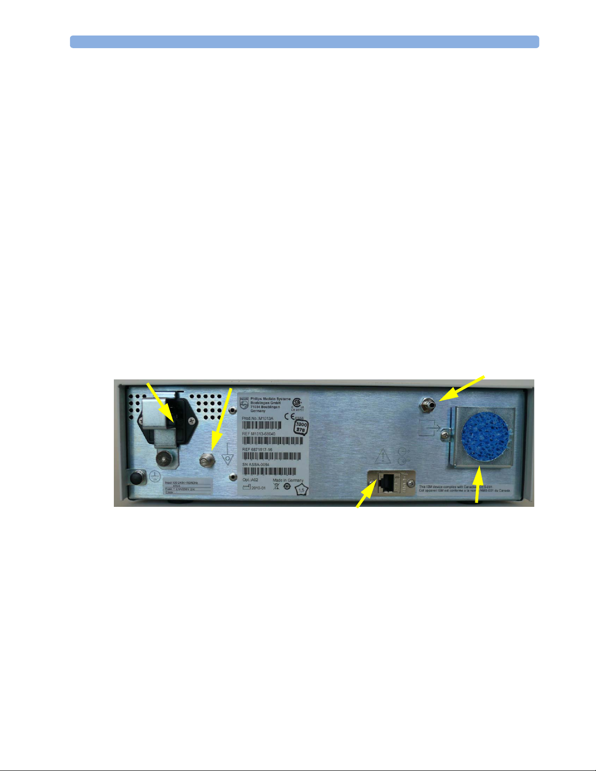
All connections to the gas analyzer are made on its rear panel. Refer to Figure 2.
Figure 2 The Rear Panel
1 Local power connector; this is a 3-pin connector, used to connect the gas analyzer to AC Power.
The gas analyzer can be operated from an AC power source of 100 - 240 V ± 10%, 50/60 Hz. The
adjustment is made automatically by the power supply inside the module.
2 RS232 Connector (RS232 Interface); this is an RJ45 connector, used to connect the gas analyzer to
the monitor.
The connection to an IntelliVue patient monitor can be made with the following cables:
• For M1013A IntelliVue G1:
– M1013A#K11 1.5 m (M1013-61001)
– M1013A#K12 3 m (M1013-61002)
• For M1019A IntelliVue G5
17

2 Installation and Patient Safety Making Connections to the IntelliVue G1/G5
– M1019A#K11 1.5 m (M1013-61001)
– M1019A#K12 3 m (M1013-61002)
3 Equipotential Grounding Terminal; this is used to connect the gas analyzer to the hospital’s
equipotential grounding system.
4 Gas exhaust. If N
O and/or other inhalation anesthetics are used during anesthesia, pollution of
2
the operating room should be prevented. Once the gas sample has passed through the gas analyzer,
it should either be returned to or removed from the anesthesia circuit.
NOTE In some countries where closed loop functionality is not available, gas must not be returned to the
anesthesia circuit.
5 Fan Filter
CAUTION Combinations of medical equipment with non-medical equipment must comply with IEC 60601-1-1.
Never use a multiple portable socket-outlet or extension cord when combining equipment unless the
socket outlet is supplied specifically for use with that equipment.
Connecting the IntelliVue G1/G5 to AC Mains
The IntelliVue G1/G5 has a wide-range power supply that allows you to operate the monitor from an
AC (alternating current) power source of 100 V to 240 V (± 10%) and 50/60 Hz (± 5%).
WARNING • Always use the supplied power cord with the earthed mains plug to connect the monitor to an
earthed AC mains socket. Never adapt the mains plug from the power supply to fit an unearthed AC
mains socket.
• Do not use AC mains extension cords or multiple portable socket-outlets. If a multiple portable
socket-outlet without an approved isolation transformer is used, the interruption of its protective
earthing may result in enclosure leakage currents equal to the sum of the individual earth leakage
currents, so exceeding allowable limits.
18
• Do not connect any devices that are not supported as part of a system.
• Any non-medical device placed and operated in the patient’s vicinity must be powered via an
approved isolation transformer that ensures mechanical fixing of the power cords and covering of
any unused power outlets.
Making Connections to the IntelliVue G1/G5 2 Installation and Patient Safety
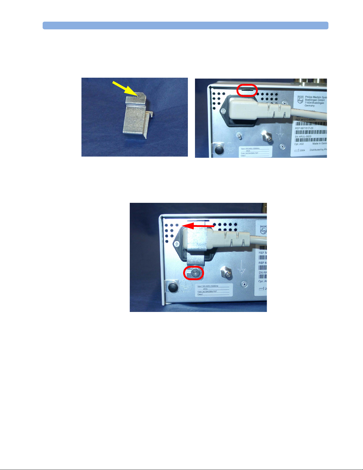
Securing the Power Cord
In order to prevent the power cord from accidentally being unplugged, secure it with the power cord
securing bracket.
1 Insert the nose of the power cord securing bracket into the small slit above the power connector.
2 Slide the bracket to the left and secure it with knurled nut.
19
2 Installation and Patient Safety Connections to the Sample Gas Exhaust
1
2
3
4
Connections to the Sample Gas Exhaust
Returning the Gas Sample
You will need the following equipment to return the gas sample to the anesthesia circuit:
Equipment Part Number Comments
Gas Exhaust Return Line M1655B Tubing includes two parts:
Tube A = 300 cm long
Tube B = 30 cm long
Gas Exhaust Return Filter M1656B Single patient use only
Gas Exhaust Tubing M1015-40001 Multi-Patient use
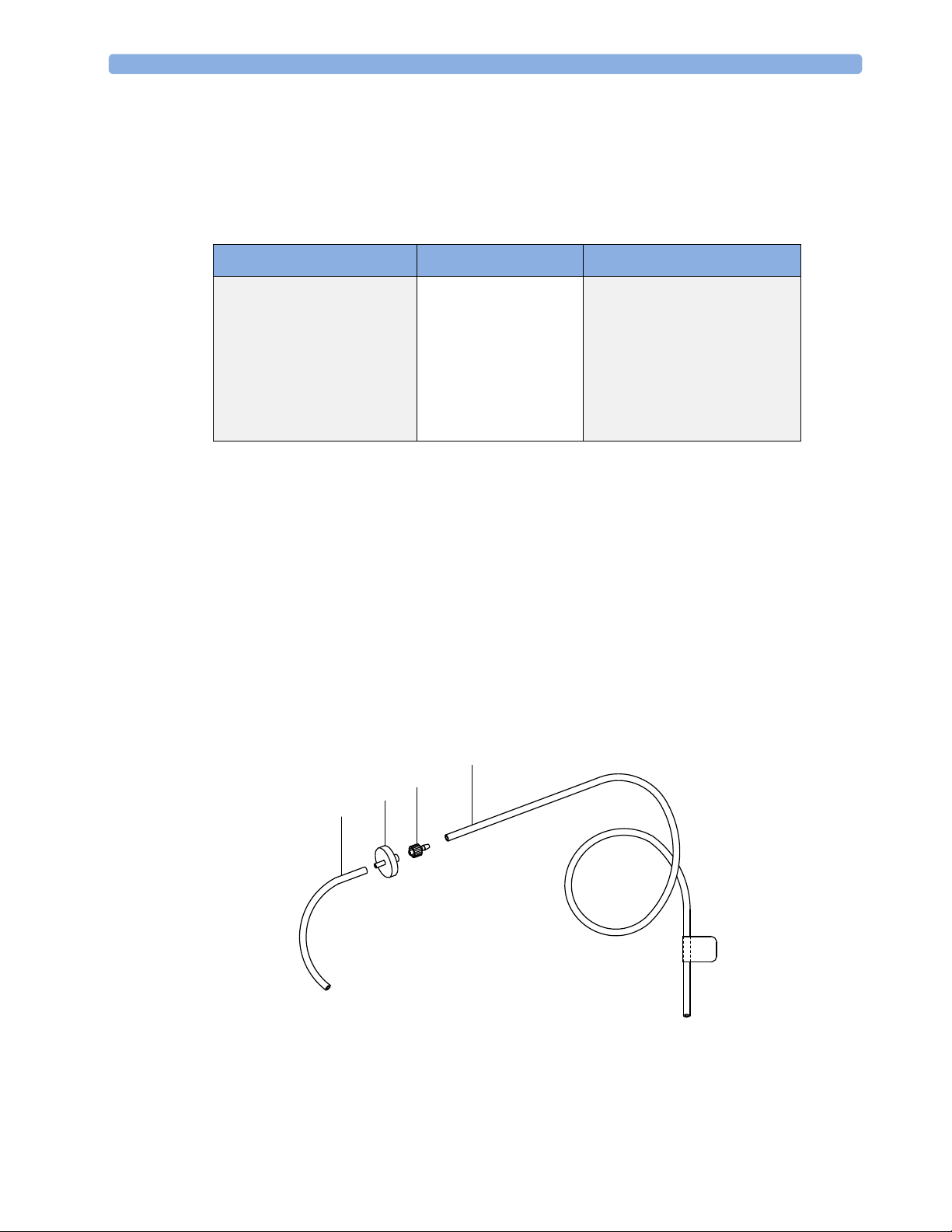
Setting Up the Gas Return
(see diagram Figure 3)
1 Fit the shorter tube tightly to the female side of the filter. Shorten the tube if it is worn or does not
fit tightly onto the filter.
NOTE When using the M1656B Gas Exhaust Return Filter with an old M1655A Gas Exhaust Return Line,
you must cut off the luer lock connection of the shorter tube first before connecting to the filter.
2 Fit the female luer lock connection (2) of the longer tube to the male side of the filter.
3 Fit the open end (5) of the longer tube to the Anesthetic Gas Exhaust outlet.
4 Fit the open end (4) of the shorter tube to the ventilation circuit.
20
Figure 3 Setting Up the M1655B Gas Exhaust Return Line
Installing the Top Mount 2 Installation and Patient Safety
NOTE
Make sure the sample gas is routed through the CO2 absorber before going back to the patient.
1 M1656B Gas Exhaust Return Filter
2 Female luer lock
3 Shorter tube connecting to the ventilation circuit
4 Longer tube connecting to the Anesthetic Gas Exhaust Outlet
Removing the Gas Sample
To remove the gas sample from the anesthesia circuit, a scavenging system needs to be connected to the
gas analyzer’s Anesthetic Gas Exhaust. If you intend to use a scavenging system with the gas analyzer,
one of the following parts must also be connected to protect it against malfunction:
1 A ventilator reservoir where the suction pressure does not exceed 70 mbar or
2 A scavenging interface, properly set and maintained (see scavenging interface manufacturer’s
instructions).
NOTE If you are not returning the gas sample into the patient’s breathing circuit, install the M1655B Exhaust
Return Tubing without the M1656B Exhaust Return Filter, shorter tube and the luer lock fitting. See
the Instructions for Use provided with the tubing and filter for further details.
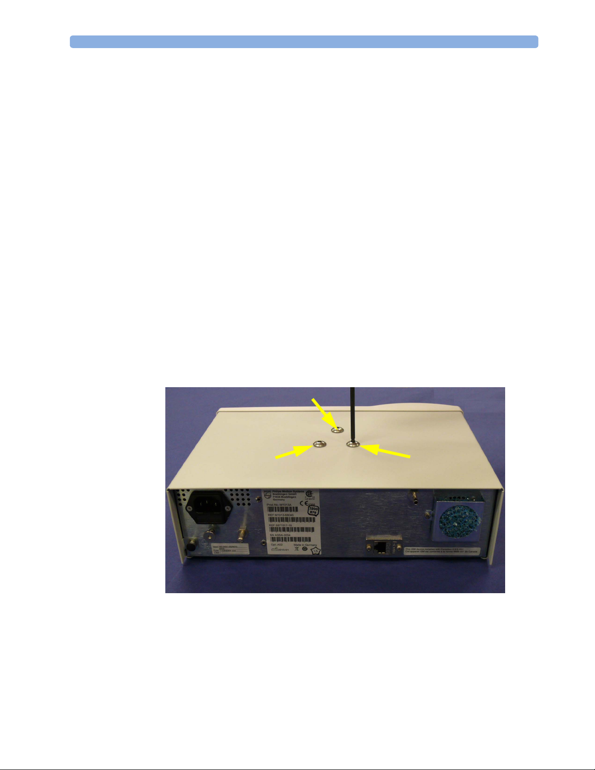
Installing the Top Mount
1 Remove the three rounded head screws on the top of the gas analyzer.
21
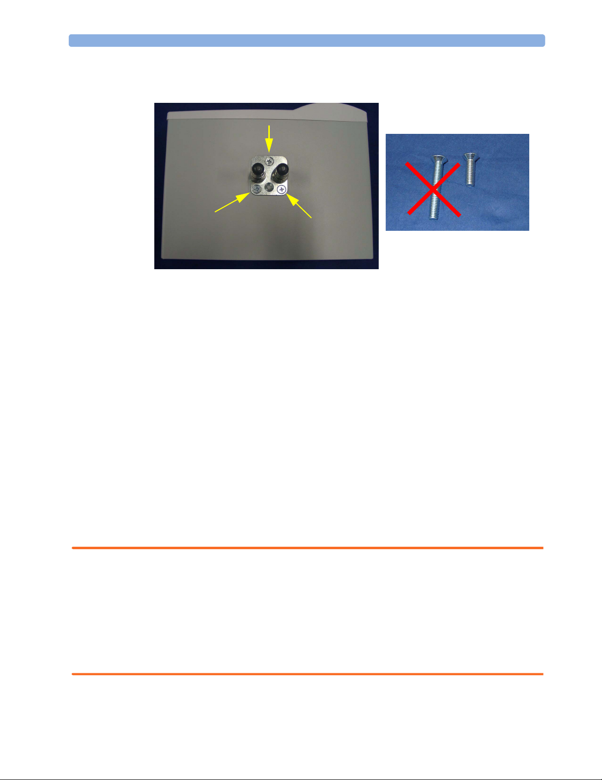
2 Installation and Patient Safety Mounting Instructions
2 Attach the top mount to the gas analyzer using only the three short countersunk screws supplied
with the mount.
NOTE Devices installed on the top mount may not weigh more than 12 kg. Make sure that any device
installed on the top mount snaps in properly and is fixed securely to the mount.
Mounting Instructions
NOTE There are different mounting options available for the IntelliVue G1 / G5. This section covers the
general concepts of safe mount installations and specific steps for the mounting options sold by Philips.
Instructions which ship with a mounting solution should always take precedence over the instructions
described in this chapter. You MUST follow the instructions that ship with the mounting solution,
regardless of manufacturer.
Please mount the IntelliVie G1 / G5 using the Philips Quick Mount solution or another approved
mounting solution. The mounting shall be done in a manner that no patient, operator or other person
can be harmed by a IntelliVue G1 / G5 removed intentionally or released accidentally from the
mount. When using the Quick Mount, be aware of the danger of accidental activation of the Quick
Mount release button when lifting or moving items located under the monitor, such as pole mounts,
etc.
For instructions on how to mount the monitor using the Quick Mount table mount refer to the
Assembly Instructions delivered with the mounting kit M8000-64100 or 453564239731.
WARNING • It is the customer's responsibility to have the attachment of the mounting hardware to the ceiling,
wall, or mounting rail and the construction of the ceiling, wall, or mounting rail evaluated for
structural integrity and compliance with all local, state and any other required codes by a registered,
professional, structural and/or mechanical engineer.
• Ensure that this commitment has been met before assembling mounts.
22
• Incorrect mounting and use of inappropriate mounting material may lead to injury. It is the
customer’s responsibility to ensure that the mounting procedures have been performed correctly and
the appropriate mounting devices have been used.

Setup and Configuration Procedures 2 Installation and Patient Safety
Setup and Configuration Procedures
This section describes final setting up and configuration procedures that must be completed after the
gas analyzer is connected to the monitor and switched on before the gas analyzer is used for
monitoring.
IntelliVue Serial Port Configuration
The MIB port used in the IntelliVue host monitor must be configured to “GM”.
To do this, go into service mode and then select Setup followed by Hardware and then MIB.
Altitude Configuration
The altitude setting for the monitor is important as it is used as a reference to check the gas analyzer
ambient pressure measurement.
See your monitor service guide for details.
Connect Sample Input Tubing
Connect the sample input tubing to the watertrap at the luer lock connector. For details, refer to the
Instructions for Use.
Post-Installation Checks
See Test and Inspection Matrix for details.
WARNING Do not use the instrument for any monitoring procedure on a patient if you identify anything which
indicates impaired functioning of the instrument.
Safety Requirements Compliance and Considerations
The M1013A IntelliVue G1 and the M1019A IntelliVue G5 comply with the following international
safety requirements for medical electrical equipment:
IEC 60601-1:1988 + A1:1991 + A2:1995; EN60601-1:1990 + A1:1993 + A2:1995; UL 606011:2003; CAN/CSA C22.2#601.1-M90; IEC 60601-1-2:2001; EN 60601-1-2:2001.
Classification (according to IEC 60601-1): Class 1, Type BF, Continuous Operation.
This ISM device complies with Canadian ICES-001. Cet appareil est conforme a la norme NMB-001
du Canada.
The possibility of hazards arising from software errors was minimized in compliance with
ISO14971:2000, EN60601-1-4:1996 + A1:1999 and IEC 60601-1-4:1996 + A1:1999.
23
2 Installation and Patient Safety Safety Requirements Compliance and Considerations
200206
0366
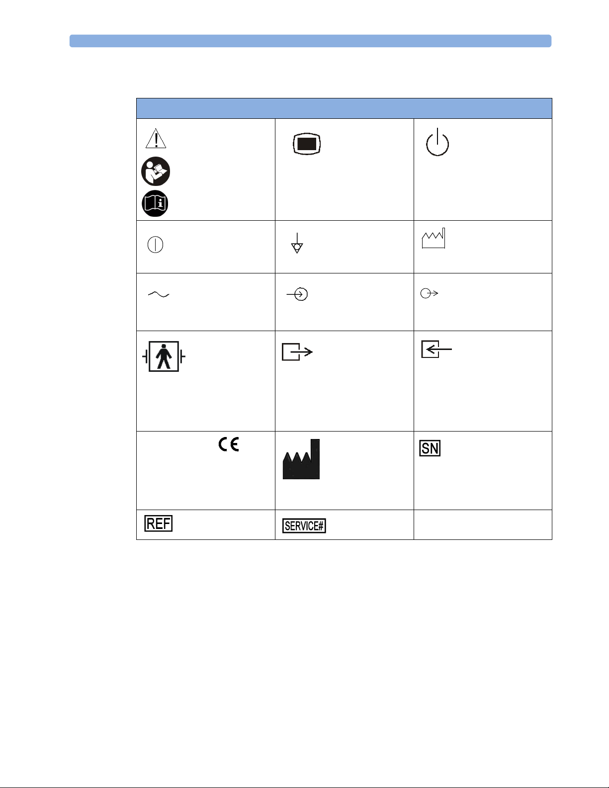
Explanation of Symbols Used
Symbols
Caution, refer to
accompanying
documents
Power On/Off*
Alternating current Electrical signal input
Applied part has
special protection
against electric
shocks (Type BF
according to IEC
60601-1)and is
defibrillator proof
The device
complies with the
requirements of the Council
Directive 93/42/EEC of 14 June
1993 (Medical Device
Directive).
Indicates location of
catalog number
Setup*
Equipotential
grounding
indicator
Gas output indicator Gas input indicator
Indicates location of
the date of
manufacture and/or
name and address of
manufacturer
Indicates location
of service number
Standby*
Identifies year
and month of
manufacture
Electrical signal output
indicator
Indicates location of
serial number
* These symbols are replaced by English text in the U.S.A.
The IntelliVue G1 and the IntelliVue G5 are protected against the effects of defibrillation and
electrosurgery.
Electrical and Safety Requirements (Customer or Philips)
Power Supply Requirements
The system and the gas analyzer can both be operated from an AC supply of 100 - 240V ±10%, 50 60Hz. The IntelliVue G1/G5 uses <25W typical and <45W peak.
24

Safety Requirements Compliance and Considerations 2 Installation and Patient Safety
Protective Earthing of the System
To protect the patient and hospital personnel, the cabinet of the installed equipment has to be
grounded. The equipment is supplied with a detachable 3-wire cable which grounds the instrument to
the power line ground (protective earth) when plugged into an appropriate 3-wire receptacle. If a 3wire receptacle is not available, consult the hospital electrician.
WARNING Do not use a 3-wire to 2-wire adapter.
Equipotential Grounding
Protection class 1 instruments are already included in the protective grounding (protective earth)
system of the room by way of grounding contacts in the power plug. For internal examinations on the
heart or the brain, Computer Module and Display Module of the System and the gas analyzer must
have separate connections to the equipotential grounding system.
One end of the equipotential grounding cable (potential equalization conductor) is connected to the
equipotential grounding terminal on the instrument’s rear panel and the other end to one point of the
equipotential grounding system. The equipotential grounding system assures that potential differences
between conductive parts are limited according to requirements of applicable standards. This safety
measure prevents that currents flowing through the heart of a patient caused by potential differences
stimulate arrhythmias.
Examinations in or on the heart (or brain) should only be carried out in rooms designed for medical
use incorporating an equipotential grounding system.
Combining Equipment
If it is not evident from the instrument specifications whether a particular instrument combination is
hazardous or not, for example, due to summation of leakage currents, the user should consult the
manufacturers concerned or an expert in the field, to ensure that the necessary safety of all instruments
concerned will not be impaired by the proposed combination.
Connecting Non-Medical Devices
Refer to the Site Preparation chapter in the respective IntelliVue Patient Monitor Service Guide for
details.
25

2 Installation and Patient Safety Safety Requirements Compliance and Considerations
26
 Loading...