

Philips LX9000R -22, LX9000R -25, LX9000R -29 Service Manual
TABLE OF CONTENTS
Technical specification..........................................................2
Locartion of printed circuit boards.........................................4
Warnings & Safety................................................................5
Brief Operating Instructions..................................................6
Dismantling Instructions......................................................15
Service hints.......................................................................24
Diagnostic Software............................................................25
Block Diagrams...................................................................59
Exploded Views..................................................................64
Circuit Diagrams and PWB LAyouts
Control board......................................................................65
Key board left......................................................................67
Key board left 2...................................................................68
A/V Front connectors..........................................................68
Key board right ...................................................................69
Power Supply primary.........................................................71
Power Supply secondary....................................................72
Auxiliary board....................................................................75
ASP (Audio Signal Processing) board................................77
MDM (Multi-channel Decvoding Module) board .................82
Amplifier board....................................................................85
Loudspeaker Socket board.................................................90
A/V board............................................................................91
µP Sub board (CECO)........................................................99
DVIO board.......................................................................103
Digital board......................................................................112
Alignments........................................................................129
Circuit- and IC descriptions...............................................132
Abbreviations A/V-, Digital-, DVIO board..........................211
Abbreviations set related..................................................217
Spare parts list..................................................................220
Version 1.0
LX9000R/22/25/29
Published by MS 0329 Service Audio Printed in The Netherlands Subject to modification © 3103 785 25200
DVD+RW Receiver
CLASS 1
LASER PRODUCT
©
Copyright 2003 Philips Consumer Electronics B.V. Eindhoven, The Netherlands
All rights reserved. No part of this publication may be reproduced, stored in a retrieval
system or transmitted, in any form or by any means, electronic, mechanical, photocopying,
or otherwise without the prior permission of Philips.
For servicing the DVD+RW Basic Engine we refer to
Service Manual 3122 785 12473
DVD+RW Basic Engine VAE8015, VAE8020
Only designated workshops can perform these repairs!

TECHNICAL SPECIFICATION
General:
Mains voltage :230V ±10% for EU versions
:120V ±10% for USA version
Mains frequency :50 Hz - 60Hz
Power consumption mains :100 W
Power consumption standby :≤ 20 W
Power consumption low power stand-by :≤ 5 W
TV Tuner
Test equipment:Fluke 54200 TV Signal generator
Test streams:PAL BG Philips Standard test pattern
System: PAL B/G, PAL D/K, SECAM L/L’, PAL I
RF - Loop Through:
Frequency range :45 MHz - 860 MHz
Gain: (ANT IN - ANT OUT) :-6 dB to 0dB
Radio Interference:
input voltage /3 tone method (+40 dB min) :no limit
Receiver:
PLL tuning with AFC for optimum reception
Frequency range :45.25 MHz - 857 MHz
Sensitivity at 40 dB S/N :≤ 60dBmV at 75W (video unweighted)
Video Performance:
Channel : 25 / 503,25 MHz,
Test pattern : PAL BG PHILIPS standard test pattern
RF Level :74 dBV
Measured on SCART 1
Frequency response :0 - 4.00 MHz +0-4dB
Group delay ( 0.1 MHz - 4.4 MHz ) :0 nsec ± 150nsec
Audio Performance:
Audio Performance Analogue - HiFi:
Frequency response at SCART 1
(L+R) output :100 Hz - 12 kHz / 0± 3dB
S/N according to DIN 45405, 7, 1967 and PHILIPS standard test
pattern video signal :FM: ≥ 50dB
AM ≥ 45dB, unweighted
Harmonic distortion (1 kHz, ± 25 kHz deviation) :FM ≤1.5%
AM ≤ 2%
Audio Performance NICAM:
Frequency response at SCART 1
(L+R) output :40 Hz - 15 kHz 0 ± 3dB
S/N according to DIN 45405, 7, 1967 and PHILIPS standard test
pattern video signal :≥ 60 dB unweighted
Harmonic distortion (1 kHz) :≤ 0.5 %
Tuning
Automatic Search Tuning
scanning time without antenna :typ. 3 min. PAL
stop level (vision carrier) :≥ 37dBmV
Maximum tuning error of a recalled program :± 62.5 kHz
Maximum tuning error during operation :± 100 kHz
Tuning Principle
automatic B,G, I, DK and L/L’detection
manual selection in "STORE" mode
Audio Tuner
Frequency range FM :87.5 MHz - 108 MHz
AM :531 kHz – 1602 kHz (EU)
530 kHz – 1700 kHz (USA)
Sensitivity at 26 dB S/N FM :≤ 5µV
AM :≤ 3250µV/m
IF FM :10.7MHz
AM :450kHz
Harmonic distortion
FM (RF=1mV, ∆f=75kHz) : ≤ 3% (1% typ.)
AM (RF=50mV/m, m=80%) : ≤ 5% (4% typ.)
Analogue Inputs
SCART 1 (Connected to TV)
Pin Signals:
1 Audio R 1.8V RMS
2 Audio R
3 Audio L 1.8V RMS
4 Audio GND
5 Blue/Chroma GND
6 Audio L
7 Blue out/ Chroma in: 0.7Vpp ± 0.1V into 75 Ohm (*)
8 Function switch <2V = TV
>4.5V / <7V = asp. ratio 16:9 DVD
>9.5V / <12V = asp. ratio 4:3 DVD
9 Green GND
10 P50 control
11 Green 0.7Vpp ±0.1V into 75 Ohm (*)
12 Nc
13 Red/Chroma GND
14 fast switch GND
15 Red out/ Chroma out 0.7Vpp ± 0.1V into 75 Ohm (*)
± 3dB 0.3Vpp Chroma (burst)
16 fast switch RGB/ CVBS or Y <0.4V into 75 Ohm = CVBS
>1V / <3V into 75 Ohm = RGB
17 Y/CVBS GND OUT
18 Y/CVBS GND IN
19 CVBS/Y 1Vpp ± 0.1V into 75 Ohm (*)
20 CVBS/Y
21 Shield
SCART 2 (Connected to AUX)
Pin Signals:
1 Audio R 1.8V RMS
2 Audio R
3 Audio L 1.8V RMS
4 Audio GND
5 Blue/Chroma GND
6 Audio L
7 Blue in/ Chroma out ± 3dB 0.3Vpp Chroma (burst)
8 Function switch
9 Green GND
10 P50 control
11 Green
12 Nc
13 Red/Chroma GND
14 fast switch GND
15 Red in/ Chroma in
16 fast switch RGB/ CVBS or Y
17 CVBS GND OUT
18 CVBS GND IN
19 CVBS/Y/RGB sync 1Vpp ± 0.1V into 75 Ohm (*)
20 CVBS/Y
21 Shield
(*) for 100% white
Audio/Video Front Input Connectors
Audio
Input voltage : 2 Vrms
Input impedance : >10kW
Video - Cinch
Input voltage : 1 Vpp ± 3dB
Input impedance : 75 W
EN 2 1. LX9000R Technical specification

Video - YC (Hosiden)
Input voltage Y :1Vpp ± 3dB
Input impedance Y :75 W
Input voltage C :burst 300 mVpp ± 3 dB
Input impedance C :75 Ohm
Video Performance
All outputs loaded with 75 Ohm
SNR measurements over full bandwidth without weighting.
SCART (RGB)
SNR : > -65 dB on all outputs
Bandwidth : 4.8 MHz ± 2dB
Audio Performance CD
Cinch Output Rear
Output voltage 2 channel mode :1.8Vrms ± 2dB
Channel unbalance (1kHz) :<1dB
Crosstalk 1kHz :<-85dB
Crosstalk 20Hz-20kHz :<-70dB
Frequency response 20Hz- 20kHz :±0.5dB max
Signal to noise ratio :>80 dB
Dynamic range 1kHz :>75dB
Dynamic range 20Hz-20kHz :>70dB
Distortion and noise 1kHz :<-70dB
Distortion and noise 20Hz-20kHz :<-55dB
Intermodulation distortion :<-77dB
Mute :>95dB
Outband attenuation :>40dB above 30kHz
Scart Audio
Output voltage 2 channel mode :1.4Vrms ± 2dB
Channel unbalance (1kHz) :<1dB
Crosstalk 1kHz :<-85dB
Crosstalk 20Hz-20kHz :<-70dB
Frequency response 20Hz- 20kHz :± 0.5dB max
Signal to noise ratio :>80 dB
Dynamic range 1kHz :>75dB
Dynamic range 20Hz-20kHz :>70dB
Distortion and noise 1kHz :<-70dB
Distortion and noise 20Hz-20kHz :<-55dB
Intermodulation distortion :<-70dB
Mute (spin-up, pause, access) :>85dB
Outband attenuation :>40dB above 25kHz
Digital Output
Coaxial
CDDA/ LPCM (incl MPEG1) :according IEC958
MPEG2, AC3 audio :according IEC1937
DTS :according IEC1937, amendment 1
Digital Video Input (IEEE 1394)
Applicable Standards
Implementation according:
IEEE Std 1394-1995
IEC 61883 - Part 1
IEC 61883 - Part 2 SD-DVCR (02-01-1997)
Specification of consumer use digital VCR’s using 6.3 mm magnetic
tape - dec.1994
Mechanical connection according: Annex A of 61883-1
P50 System Control
Via SCART pin nr 10
Power Amplifier
Power stage protection :temperature and short circuit
Output power
Stereo mode (1kHz, 10% distortion) :2x 70W rms
Surround mode (1kHz, 10% distortion)
Front :2x 80W rms
Centre :80W rms
Surround :2x 80W rms
Sub Woofer :80W rms
Headphone
3.5mm stereo jack, 8 - 600 Ohm
2.8V EMF
Dimensions and Weight
Height of feet :10mm
Apparatus tray closed :WxDxH :435 x 405 x 96mm
Weight without packaging :appr. 9 kg (main set)
appr. 19.7kg (speaker boxes)
Weight in packaging :appr. 28.7 kg
Laser Output Power & Wavelength
DVD
Output power during reading :0.8mW
Output power during writing :20mW
Wavelength :660nm
CD
Output power :0.3mW
Wavelength :780nm
EN 31.LX9000RTechnical specification
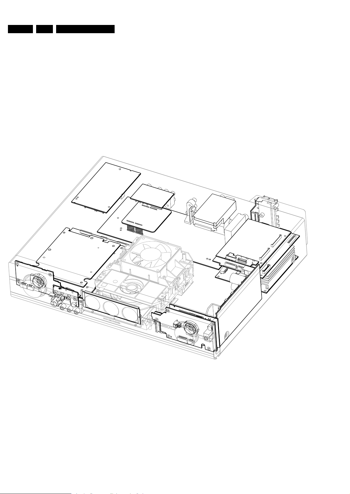
EN 4 1. LX9000R Location of printed boards
POWER SUPPLY BOARD
primary
POWER SUPPLY BOARD
secondary
AUXILIARY BOARD
DIGITAL BOARD
DVIO BOARD
KEY BOARD right
DISPLAY ASSY
A/V FRONT CONNECTORS
KEY BOARD left 2
KEY BOARD left
CONTROL BOARD
ANALOG VIDEO BOARD
(A/V BOARD)
MDM BOARD
AUDIO TUNER
LS SOCKET
BOARD
ASP BOARD
AMPLIFIER BOARD
µP SUB BOARD
(CENTRAL CONTROLLER CECO)
DISPLAY
POS. SWITCH
Location PCBs LX9000R, 100703
LOCATION OF PRINTED BOARDS
figure 1
EN 52.LX9000RSafety Information
© WARNING
All ICs and many other semiconductors are susceptible to
electrostatic discharges (ESD). Careless handling during
repair can reduce life drastically.
When repairing, make sure that you are connected with the
same potential as the mass of the set via a wristband with
resistance. Keep components and tools at this potential.
f ATTENTION
Tous les IC et beaucoup d´autres semi-conducteurs sont
sensibles aux décharges statiques (ESD). Leur longévite
pourrait être considérablement écourtée par le fait qu´aucune
précaution nést prise à leur manipulation.
Lors de réparations, s´assurer de bien être relié au même
potentiel que la masse de l´appareil et enfileer le bracelet
serti d´une résistance de sécurité.
Veiller à ce que les composants ainsi que les outils que l´on
utilise soient également à ce potentiel.
d WARNUNG
Alle ICs und viele andere Halbleiter sind empfindlich
gegenüber elektrostatischen Entladungen (ESD).
Unsorgfältige Behandlung im Reparaturfall kann die
Lebensdauer drastisch reduzieren.
Sorgen Sie dafür, daß Sie im Reparaturfall über ein Pulsarmband mit Widerstand mit dem Massepotential des
Gerätes verbunden sind.
Halten Sie Bauteile und Hilfsmittel ebenfalls auf diesem
Potential.
ñ WAARSCHUWING
Alle IC´s en vele andere halfgeleiders zijn gevoelig voor
electrostatische ontladingen (ESD).
Onzorgvuldig behandelen tijdens reparatie kan de levensduur
drastisch doen vermindern. Zorg ervoor dat u tijdens reparatie
via een polsband met weerstand verbonden bent met hetzelfde
potentiaal als de massa van het apparaat.
Houd componenten en hulpmiddelen ook op ditzelfde potentiaal.
i AVVERTIMENTO
Tutti IC e parecchi semi-conduttori sono sensibili alle scariche
statiche (ESD).
La loro longevità potrebbe essere fortemente ridatta in caso di
non osservazione della più grande cauzione alla loro
manipolazione. Durante le riparationi occorre quindi essere
collegato allo stesso potenziale che quello della massa
delápparecchio tramite un braccialetto a resistenza.
Assicurarsi che i componenti e anche gli utensili con quali si
lavora siano anche a questo potenziale.
©
Safety regulations require that the set be restored to its
original condition and that parts which are identical with
those specified be used.
Safety components are marked by the symbol
i
Le norme di sicurezza estigono che l´apparecchio venga
rimesso nelle condizioni originali e che siano utilizzati i
pezzi di ricambiago identici a quelli specificati.
Componenty di sicurezza sono marcati con
ñ
Veiligheidsbepalingen vereisen, dat het apparaat in zijn
oorspronkeliijke toestand wordt teruggebracht en dat
onderdelen, identiek aan de gespecificeerde, worden toegepast.
De Veiligheidsonderdelen zijn aangeduid met het symbool
s Varning !
Osynlig laserstrålning när apparaten är öppnad och
spärren är urkopplad. Betrakta ej strålen.
∂ Advarsel !
Usynlig laserstråling ved åbning når sikkerhedsafbrydere
er ude af funktion. Undgå udsaettelse for stråling.
ß Varoitus !
Avatussa laitteessa ja suojalukituksen ohitettaessa olet alttiina
näkymättömälle laserisäteilylle. Älä katso säteeseen !
f
"Pour votre sécurite, ces documents doivent être utilisés par
des spécialistes agréés, seuls habilités à réparer votre
appareil en panne".
ESD
SAFETY
d
Bei jeder Reparatur sind die geltenden Sicherheitsvorschriften zu beachten. Der Originalzustand des Gerätes
darf nicht verändert werden. Für Reparaturen sind Originalersatzteile zu verwenden.
Sicherheitsbauteile sind durch das Symbol markiert.
f
Les normes de sécurité exigent que l`appareil soit remis
à l`état d`origine et que soient utilisées les pièces de
rechange identiques à celles spécifiées.
Les composants de sécurité sont marqués
CLASS 1
LASER PRODUCT
©
DANGER: Invisible laser radiation when open.
©
After servicing and before returning the set to customer
perform a leakage current measurement test from all
exposed metal parts to earth ground, to assure no
shock hazard exists.
The leakage current must not exceed 0.5mA.
AVOID DIRECT EXPOSURE TO BEAM.
©
AVAILABLE ESD PROTECTION EQUIPMENT :
anti-static table mat large 1200x650x1.25mm 4822 466 10953
small 600x650x1.25mm 4822 466 10958
anti-static wristband 4822 395 10223
connection box (3 press stud connections, 1MΩ) 4822 320 11307
extendible cable (2m, 2MΩ, to connect wristband to connection box) 4822 320 11305
connecting cable (3m, 2MΩ, to connect table mat to connection box) 4822 320 11306
earth cable (1MΩ, to connect any product to mat or to connection box) 4822 320 11308
KIT ESD3 (combining all 6 prior products - small table mat) 4822 310 10671
wristband tester 4822 344 13999
EN 6 3. LX9000R Brief Operating Instructions
BRIEF OPERATING INSTRUCTIONS
The following excerpt of the Owner´s Manual serves as a very short introduction to the set.
The complete Owners Manual can be downloaded in several languages from the Internet site of
Philips Customer Care Center: www.p4c.philips.com
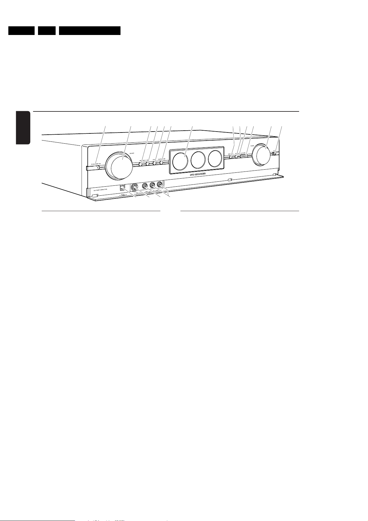
Controls and connections
English
1
23456 7
%&^
$
0! @ #
9
8
Controls on the front
1 2 STANDBY·ON
switches the set on or to standby
2 SOURCE
selects a source
3 4 SEARCH
skips to the beginning of the current or previous
chapter/title/track of the inserted disc, searches backwards
4 SEARCH ¢
skips to the beginning of the next chapter/title/track
of the inserted disc, searches forwards
5 STOP 9
stops playback or recording
6 PLAY/PAUSE 2;
starts/pauses playback
7 display/DVD recorder drawer
8 OPEN/CLOSE /
opens/closes the DVD recorder drawer
9 SURR.
selects the different surround modes
0 INSTANT – RECORD (status light)
indicates if immediate recording is possible
! RECORD
starts recording a TV channel or an external
video source selected on the DVD recorder system
(the key is illuminated while recording is in progress)
@ VOLUME
adjusts the volume
Connections on the front
# PHONES
3.5 mm headphone socket
$ DV IN / CAM 2
connect to the i.Link output of your Digital Video (DV) or
Digital 8 camcorder
% S-VIDEO / CAM 1
connect to the S-video output of your Hi-8 or S-VHS
camcorder
^ VIDEO / CAM 1
connect to the video (CVBS) output of your camcorder
& AUDIO LEFT/RIGHT / CAM 1
connect to the audio output of your camcorder
10
EN 73.LX9000RBrief Operating Instructions
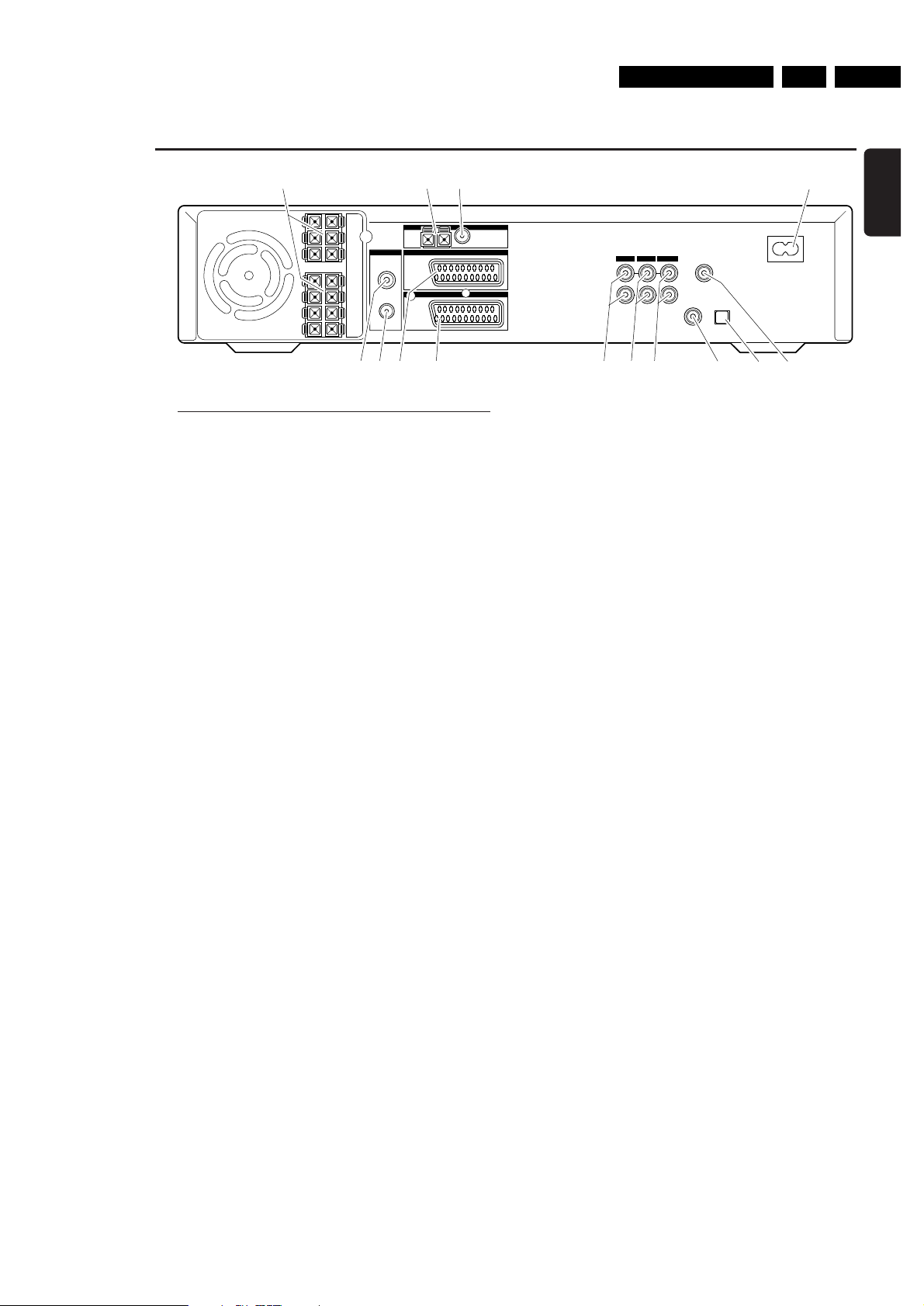
Controls and connections
TV ANTENNA
IN
TV OUT
EXT 2
EXT 1
MW FM
AUX I/0
TO TV I/0
L
R
L
R
DIGITAL OUT
DIGITAL IN
OPTICAL IN
LINE IN 1 LINE IN 2 LINE OUT
MAINS ~
RADIO
CENT.
4Ω
SURR
LEFT
4Ω
SURR
RIGHT
4Ω
SUB
LEFT
8Ω
FRONT
LEFT
4Ω
FRONT
RIGHT
4Ω
SUB
RIGHT
8Ω
2 3
4
5 76 8 @ # $9 0 !
1
English
Connections on the rear
1 connect to the supplied speakers
2 RADIO / MW
connect to the MW antenna
3 RADIO / FM
connect to the FM antenna
4 MAINS ~
After all other connections have been made,
connect the mains lead to the wall socket.
5 TV ANTENNA / IN
connect to the TV antenna
6 TV ANTENNA / TV OUT
connect to the TV antenna input of your TV
7 EXT 2 / AUX I/O
connect to the SCART socket of an external video
appliance
8 EXT 1 / TO TV I/O
connect to the SCART socket of the TV
9 LINE IN 1 L/R
connect to the analogue audio output of an external
appliance (e. g. tape deck, CD changer, …)
0 LINE IN 2 L/R
connect to the analogue audio output of an external
appliance (e. g. tape deck, CD changer, …)
! LINE OUT L/R
connect to the analogue audio input of an external
appliance (e. g. tape deck, …)
@ DIGITAL IN
connect to the digital coaxial output of a digital appliance
# OPTICAL IN
connect to the digital optical output of a digital appliance
$ DIGITAL OUT
connect to the digital coaxial input of a digital appliance
Before starting with the connections, make sure all
appliances that you want to connect as well as the
DVD recorder system are disconnected from the
power sockets.
11
EN 8 3. LX9000R Brief Operating Instructions
TV
CDR/TAPE
CAM 1/2
CD
TUNER
SAT
MENU
REC MODE
DISC DISPLAY
CLEAR RETURNEDIT
PLAY MODE
TREBLE
TIMER
LOUDNESS
VCR/GAME
DVD/MON
BASS
SUBWOOFER
REAR
NIGHT
VOICE
TV VOL
REC/OTR
CHVOL
MUTE
SELECT
SURR.
+
-
AUDIODISC
É
É
É
É
0
OK
H
§
T/C
SURR.
2
;
∞
9
1
3
2
4
6
5
79
8
SYSTEM
2
1
2
3
4
7
8
9
!
%
(
)
^
£
≤
§
•
ª
&
*
¡
™
∞
≥
5
6
$
@
0
#
º
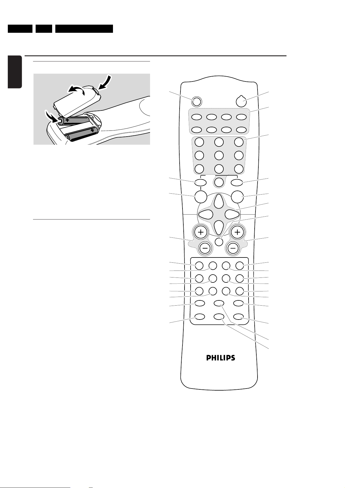
Remote Control
English
Inserting the batteries
1 Open the battery compar tment of the remote control and
insert 2 alkaline batteries, type AA (R06, UM-3).
2 Close the battery compar tment.
Do not use old and new or different types of batteries in
combination.
Remove batteries if they are empty or if the remote control
will not be used for a long time.
Batteries contain chemical substances, so they should
be disposed of properly.
Using the remote control
With this remote control you can control the
DVD recorder system as well as other Philips appliances
such as a Philips TV,VCR or CD player.
To control a Philips appliance, briefly press the
corresponding source key (TV, SAT, CAM 1/2, CD, CDR or
VCR) on the remote control. Some of the remote control
keys, e. g. 2, 0–9, CH+, CH–, 4, ¢, 9, 2; can be used
to control the appliance then.To control the DVD recorder
system with these keys, press TUNER or DVD/MON.
To select a source on the DVD recorder system, keep the
source key (TV, SAT, CAM 1/2, CD, CDR or VCR) on the
remote control pressed for 1 second.
To select CAM 2 (or TAPE, GAME), fir st select CAM 1 (or
CDR,VCR), then keep the corresponding key pressed for
1 second.
To control the DVD recorder system, please point the
remote control at the DVD recorder system and not at
the TV.
8

EN 93.LX9000RBrief Operating Instructions
Remote control keys
1 2
switches the DVD recorder system and a Philips appliance
on or to standby
2 REC/OTR
starts recording the TV channel or video source selected
on the DVD recorder system
3 DVD/MON
selects the disc in the tray or the TV channel selected on
the DVD recorder system
TV
selects the TV
TUNER
selects the radio tuner, selects the waveband and switches
between FM mono and FM stereo
SAT
selects a connected satellite receiver
CAM 1/2
selects the camcorder inputs on the front
CD
selects a connected CD player
CDR/TAPE
selects a connected CD recorder, tape deck or similar
VCR/GAME
selects a connected VCR or game console
4 0–9 to key in numbers 0–9
5 DISC MENU
enters the disc menu
6 SYSTEM MENU
enters the system menu of the DVD recorder system
7 AUDIO MENU / SELECT
enters the audio menu of the DVD recorder system and
selects an option in the system menu
8 OK
confirms menu options
9 Arrow keys 1, 3,2, 4
to move in a menu
0 VOL +, VOL
increases/decreases the volume of the DVD recorder
system
! H
mutes the sound of the DVD recorder system
@ CH +, CH
selects a TV channel on the DVD recorder system and
selects a preset radio station
–
–
Remote Control
# 4 /
$ ¢ / TV VOL+
% 2;
^ 9
& REC MODE
* PLAY MODE
( DISPLAY
) T/C / DISC
¡ TIMER
™ EDIT
£ SURR. / RETURN
≤ CLEAR
∞ SUBWOOFER
§ LOUDNESS
≥ REAR
• VOICE / NIGHT
ª TREBLE
º BASS
–
TV VOL
skips to the beginning of the current or previous
chapter/title/track of the inserted disc, searches backwards,
tunes to a radio station with a lower frequency and
decreases the volume of a Philips TV
skips to the beginning of the next chapter/title/track of the
inserted disc, searches forwards,
tunes to a radio station with a higher frequency and
increases the volume of a Philips TV
starts/pauses playback and closes the disc tray
stops playback or recording
selects a recording mode: HQ, SP, SP+, LP, EP or EP+
selects different playback modes like REPEAT or SHUFFLE
selects various display information
switches between title, track and chapter and
changes discs on a Philips CD changer
enters the timer recording menu
enters the menu Favorite Scene Selection
selects the different surround modes and
returns to the previous menu on a (Super) Video CD
clears an entry (eg. timer preset)
(
in combination with VOL+ or VOL
adjusts the subwoofer volume
switches loudness on and off
(
in combination with VOL+ or VOL
adjusts the volume of the rear speakers
switches Clear Voice or Night mode on or off
(
in combination with VOL+ or VOL
adjusts the treble
(
in combination with VOL+ or VOL
adjusts the bass
−)
−)
−)
English
−)
9
EN 10 3. LX9000R Brief Operating Instructions
7
2
1
3
!
!
@
@
!
0
9
8
!
#
4
5
6
English
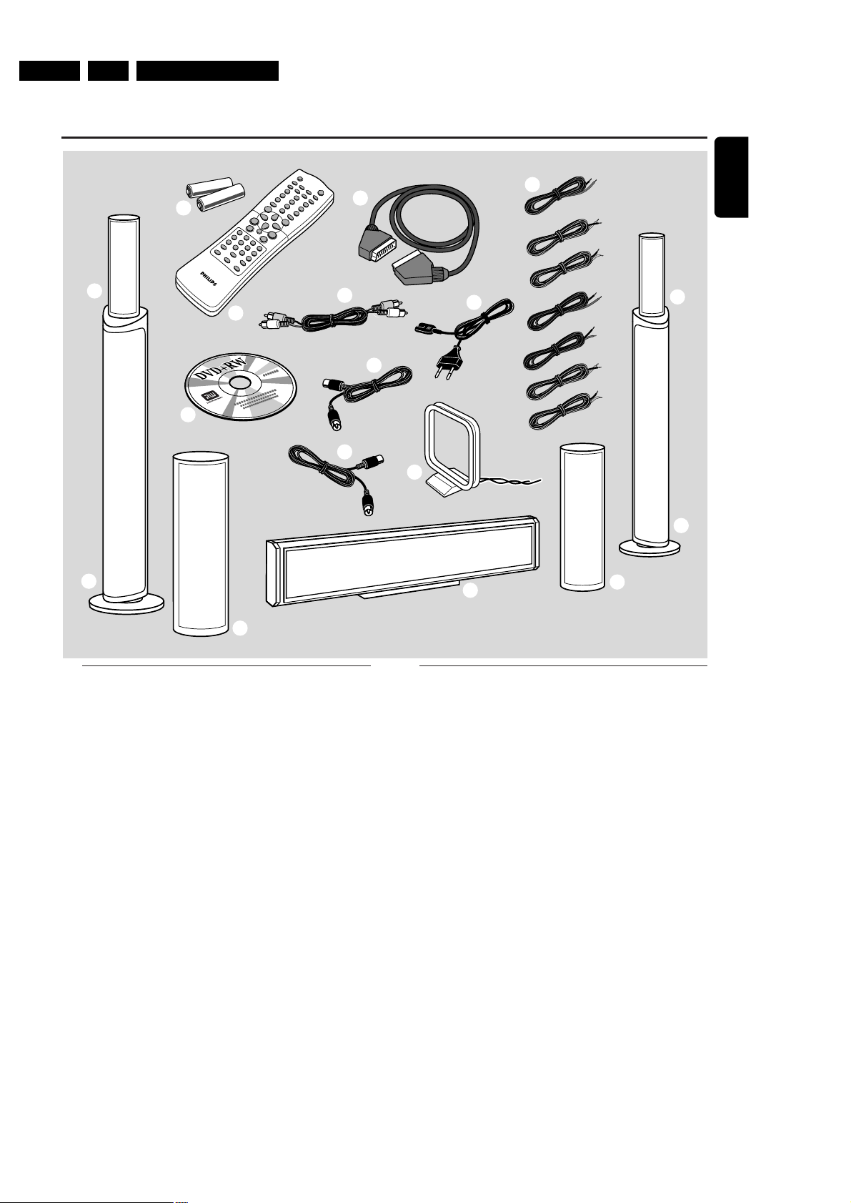
Quick use guide LX9000R
General information
This Quick use guide gives a rough overview and helps
to quickly start with basic steps. Please read the supplied
user´s manual for detailed information.
Supplied accessories
1 2 batteries for the remote control, type AA
2 1 remote control
3 1 blank DVD+RW disc
4 1 SCART cable
5 1 cinch audio cable
6 1 TV antenna cable
7 1 FM antenna cable
8 1 MW loop antenna
9 1 AC mains cable
0 7 speaker cables with colour coded ends
! 2 front speakers and 2 rear speakers
@ 2 subwoofers integrated in the speaker stands
# 1 centre speaker
1
EN 113.LX9000RBrief Operating Instructions
Quick use guide LX9000R
CENT.
4Ω
SURR
LEFT
4Ω
SURR
RIGHT
4Ω
SUB
LEFT
8Ω
FRONT
LEFT
4Ω
FRONT
RIGHT
4Ω
SUB
RIGHT
8Ω
front L
subwoofer L
rear L rear R
centre
front R
subwoofer R
front R,
subwoofer R
front L,
subwoofer L
rear L rear R
centre
or
to place the
rear speakers
on a shelf or
on the floor
to hang the
rear speakers
on the wall
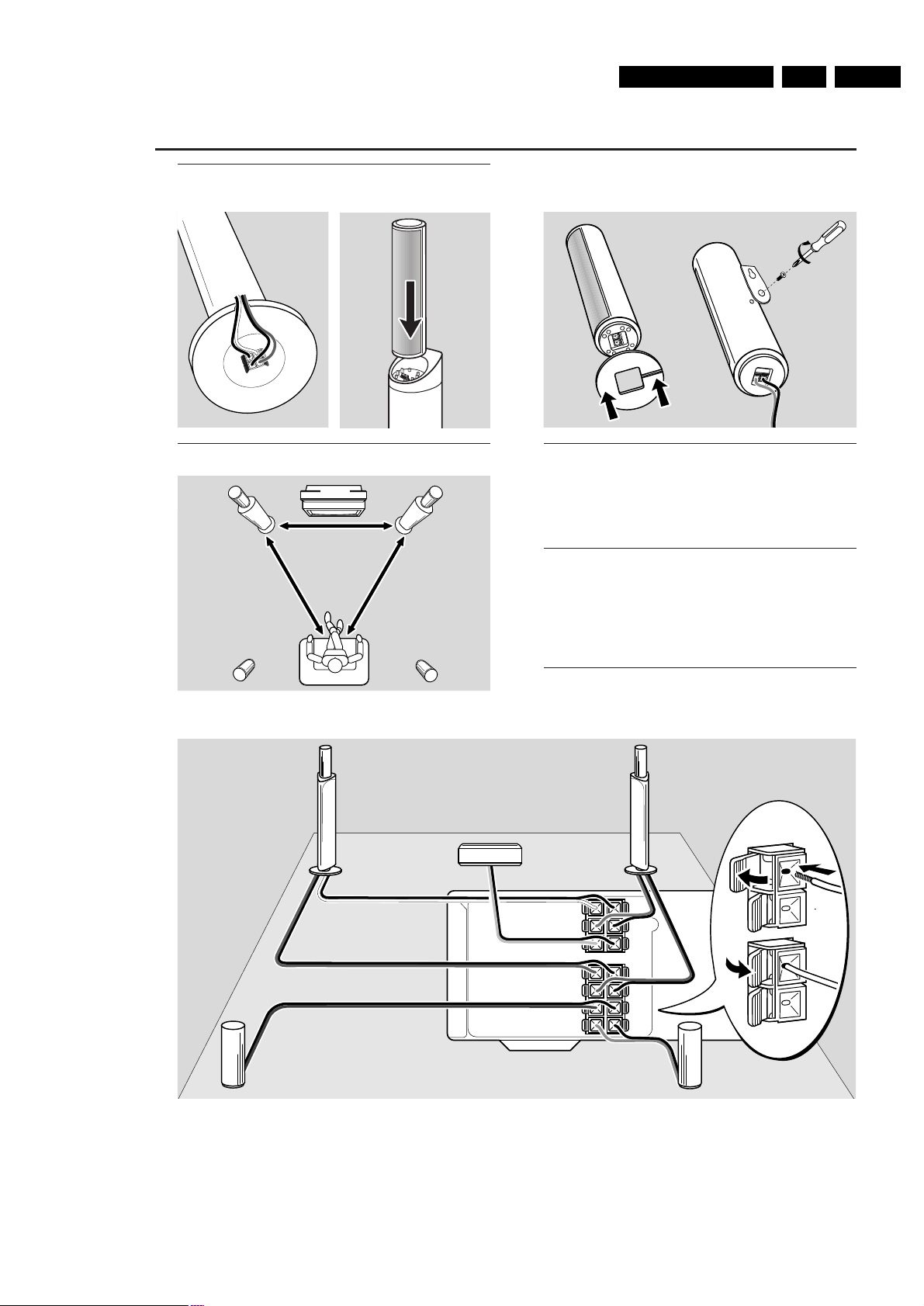
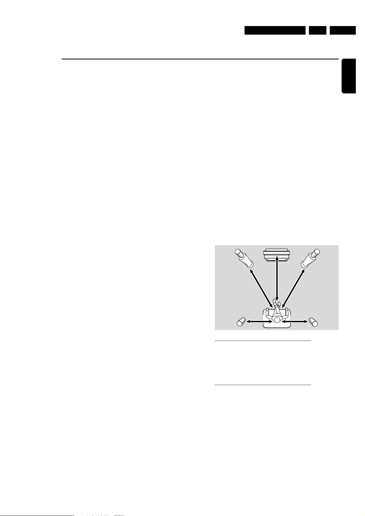
Assembling the speakers
Subwoofers and front speakers
Positioning the speakers
Rear speakers
Connecting the speakers
Connect the speakers using the supplied speaker cables.
Match the colours of the speaker sockets and the speaker
cables:
Speaker
+ −
Front Left white black
Front Right red black
Centre green black
Subwoofer Left violet black
Subwoofer Right violet black
Rear Left blue black
Rear Right grey black
2
EN 12 3. LX9000R Brief Operating Instructions
TV ANTENNA
IN
TV OUT
EXT 2
EXT 1
MW FM
AUX I/0
TO TV I/0
L
R
L
R
DIGITAL OUT
DIGITAL IN
OPTICAL IN
LINE IN 1 LINE IN 2 LINE OUT
MAINS~
RADIO
EXT. IN
TO TV
TO TV
DIGITAL OUT
DIGITAL IN
OPTICAL
OUT
TV OUT
ANTENNA
EXT IN
ANTENNA IN
AM ANTENNA
FM ANTENNA
TV ANTENNA
Make sure all
other connections
have been made
before connecting
the mains cable to
AC MAINS ~ and
to the wall socket.
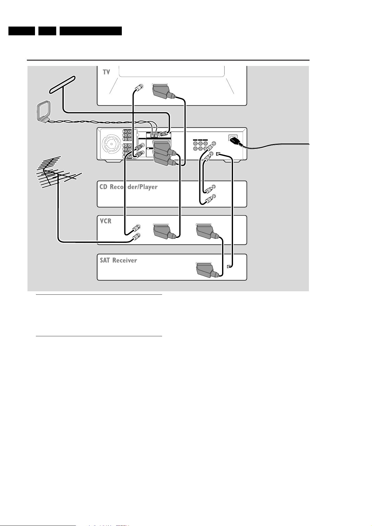
Quick use guide LX9000R
Connections
Scart inputs/outputs of your other appliances can be
named:
– TO TV/MONITOR, EURO-AV OUT,…
– AUX, EXT, I/0, EURO-AV IN,…
Initial installation
When you connect the DVD recorder system to the mains
supply for the first time, you need to perform some basic
settings. Please observe the TV screen and the display of
the DVD recorder system.
1 Switch on your TV.
2 Connect the supplied mains cable to AC MAINS ~ and to
the wall socket. If the DVD recorder system is in demo
mode, press 2 to cancel the demo mode.
➜ IS TV ON? is displayed on the DVD recorder system.
3 If necessary set the TV to the correct audio/video channel
for the DVD recorder system. Such channels may be called
AUX or AUXILIARY IN, AUDIO/VIDEO or A/V IN, EXT1,
EXT2 or EXTERNAL IN, etc. These channels are often near
channel 00.
Note: If your TV supports EasyLink, the TV and the DVD
recorder system exchange information via the SCART cable.
In this case, EasyLink loading data from TV, please
wait will appear on the TV. Some of the following settings will
be done automatically then.
4 ➜ The menu Menu Language appears on the TV screen.
Press 3 or 4 to select the language in which the display
messages should appear on the TV screen.Then press OK.
5 ➜ The menu Audio language appears.
Press 3 or 4 to select the language in which DVDs should
preferably be played, if the language is available on the disc.
Then press OK.
3
EN 133.LX9000RBrief Operating Instructions
Quick use guide LX9000R
3 m
3 m
3 m
1.5 m 1.5 m
English
6 ➜ The menu Subtitle Language appears.
Press 3 or 4 to select the language in which subtitles
should preferably be displayed, if subtitles in the language
are available on the disc.Then press OK.
7 ➜ The menu TV Shape appears.
Press 3 or 4 to select the screen format. This setting will
have an effect only with DVDs supporting different screen
formats.
➜ 4:3 letterbox: for a wide-screen picture (cinema
format) on a conventional 4:3 TV set with black borders
at the top and bottom of the screen.
➜ 4:3 panscan: for a full-height picture with cropped
edges.
➜ 16:9: for a wide-screen TV set.
Then press OK.
8 ➜ The menu Country appears.
Press 3 or 4 to select the countr y where the
DVD recorder system is used. If your countr y does not
appear, select Other.Then press OK.
9 ➜ If you have connected the antenna - press OK
appears.
If you connected the DVD recorder system to a
TV antenna or a cable TV system, press OK.
If not, connect the antenna, then press OK.
➜ Searching for TV channels appears.The search
may take several minutes.
10 ➜ Time, Year, Month and Date appear.
If the time and date are set correctly continue with step 13,
else press 4 or 3 repeatedly to select either Time, Year,
Month or Date.
11 Press 1 or 2 or 0–9 repeatedly to set the correct value.
12 Repeat steps 10–11 until all settings of the time and date
are correct.
13 Press OK.
➜ CONTINUE WITH SPECIAL AUDIO SETTINGS is
scrolled on the DVD recorder system.
Next, you will be asked
– about the distances between the speakers and your
preferred listening position and
– to which socket you connected your TV and other
appliances.
14 If you want to continue with these advanced settings:
Press OK. For details, see “Advanced settings” on page 17 in
the user´s manual.
If you do not want to continue, the standard settings
below will be used for the speaker distances and the
connections:
Press 4 to select NO, then press OK to confirm.
➜ AUTOINSTALL is displayed.The DVD recorder system
searches for available radio stations and stores them in its
memory.
➜ After the search INSTALLATION COMPLETE is
scrolled and a radio station is played.The DVD recorder
system is ready to play.
Standard settings for the speaker distances and
the connected appliances
To change these settings later on, see “When adding
appliances or changing the connections of appliances” and
“When changing the speaker setup” in the user´s manual.
appliance is connected to
TV EXT 1 TO TV I/O
satellite receiver EXT 2 AUX I/O
VCR (video recorder) EXT 2 AUX I/O
game console EXT 2 AUX I/O
CD player DIGITAL IN
CD recorder LINE IN 1
tape deck LINE IN 2
Note:The satellite receiver, VCR and game console are
connected in a “chain”. See illustration on the page to the left.
4

EN 14 3. LX9000R Brief Operating Instructions
Quick use guide LX9000R
Discs for playback and recording
– DVD+R
can be recorded once and played
on standard DVD players and
DVD recorders, if finalised.
– DVD+RW
can be recorded, erased and
re-recorded many times and played on
DVD+RW compatible DVD players
and DVD recorders if finalised.
Discs for playback only
Discs with the following logos can be played:
Playback
1 Press OPEN/CLOSE / on the set to open the drawer and
insert a disc (printed side up) in the tray.
2 Press OPEN/CLOSE / on the set again. If necessary, press
PLAY/PAUSEÉÅ to start playback.
0
To interrupt playback, press PLAY/PAUSEÉÅ.
0
To resume playback, press PLAY/PAUSEÉÅ again.
3 To stop playback press STOP.
Selecting a source
● Turn SOURCE on the DVD recorder system or keep a
source key on the remote control pressed for 1 second to
select either:
– the disc in the DVD recorder system
o
– MONITOR: the internal TV tuner of the DVD
l
recorder system (only selectable by pressing
DVD/MON on the remote control)
– TV: the TV
e
– CAM1: a camcorder connected to CAM1
m
– CAM2: a camcorder connected to CAM2
n
– SAT: a connected satellite receiver
i
– VCR: a connected VCR (video recorder)
j
– GAME: a connected game console
r
– the radio tuner of the DVD recorder system
f
– TAPE: a connected tape deck or similar audio
k
recording appliance
– CDR: a connected CD recorder
p
– CD: a connected CD player/changer
q
➜ The sound of the source is played on the DVD recorder
system.
Note: If SOURCE NOT AVAILABLE is scrolled please read
“When adding appliances or changing the connections of
appliances” in the user´s manual.
5
DISMANTLING INSTRUCTIONS
EN 154.LX9000RDismantling Instructions
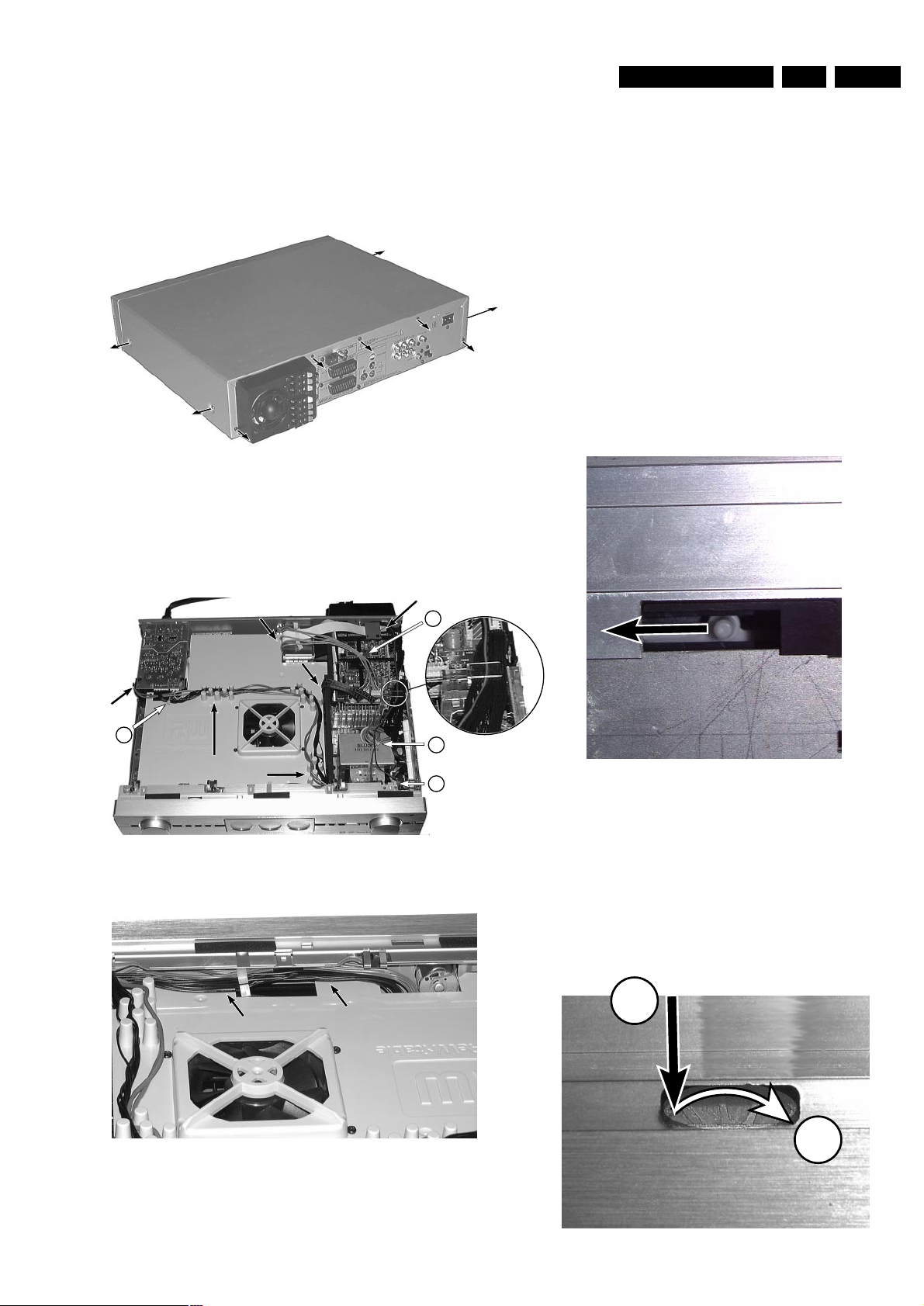
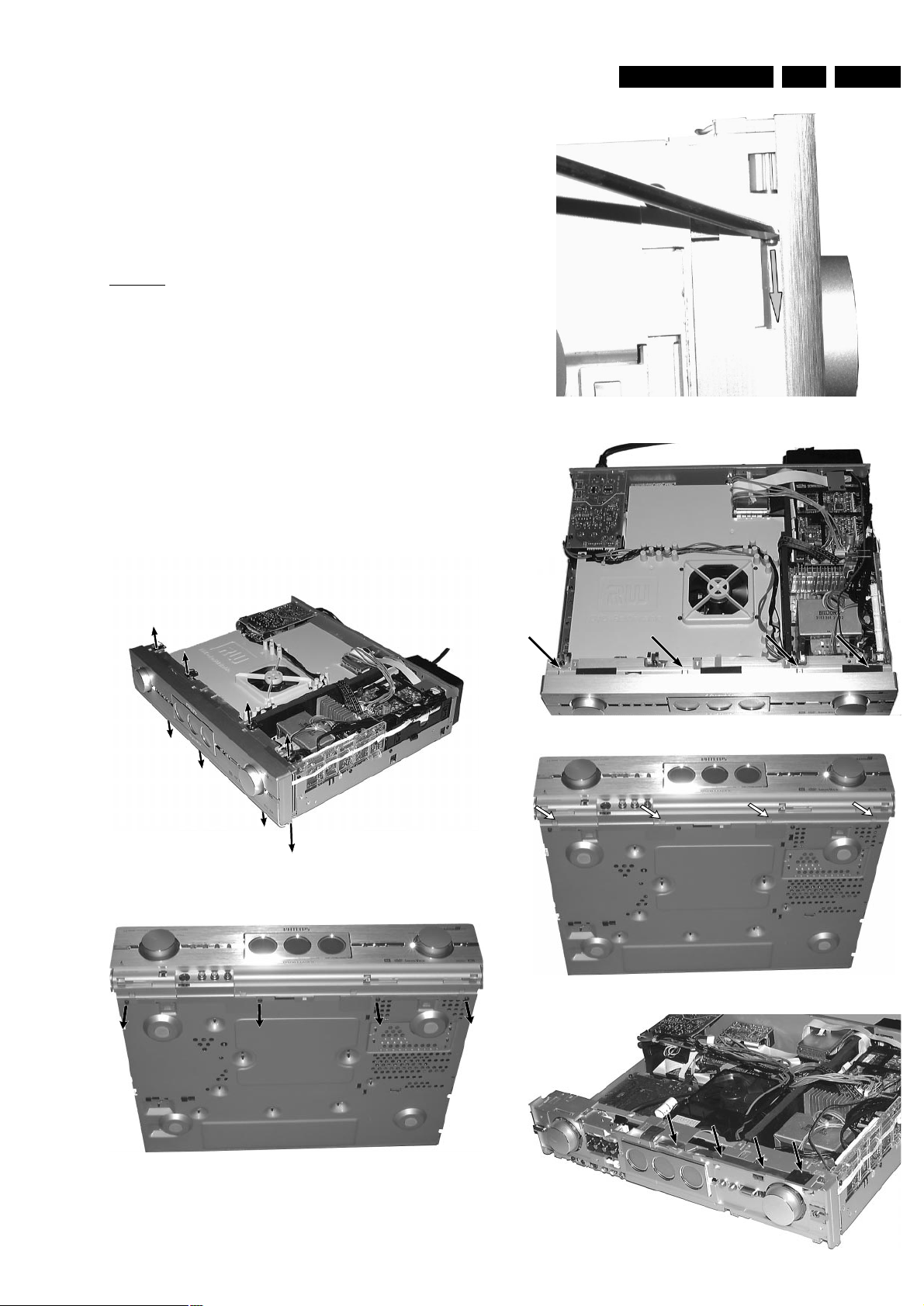
Dismantling the
Top Cover
picture 1
• Remove 9 screws as shown in picture 1.
• Raise top cover at the rear and pull it backwards.
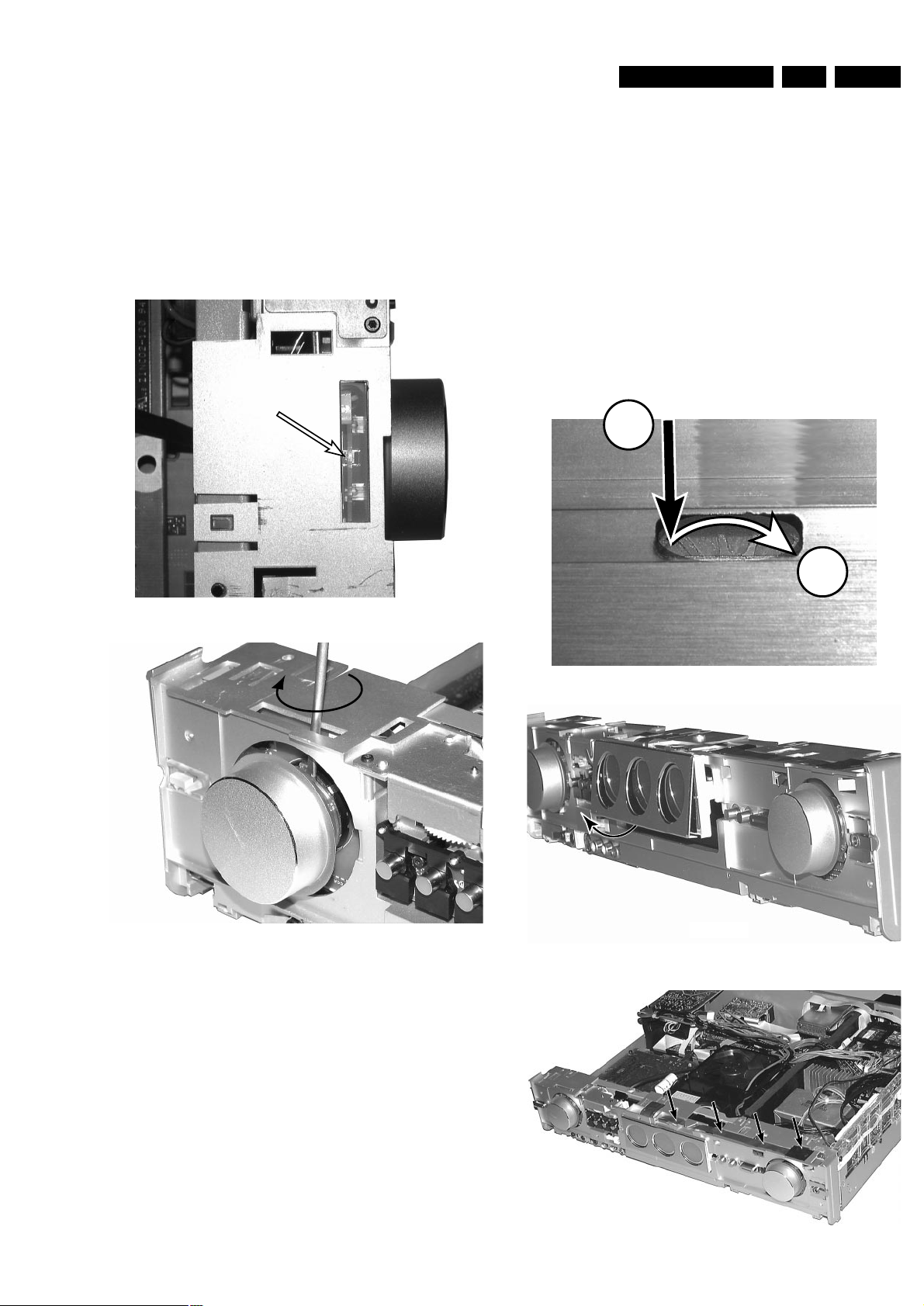
Manual opening of the tray
In case the loader is defect or cannot be opened electrically, proceed
as follows:
a) Display can be moved out electrically
• Press
Open/Close
to move display out first.
• The tray can now be released by means of screwdriver. Through
a slot on the bottom side of the front cabinet the locking slider of
the tray can be accessed. Move the white pin of the slider to the
left side ( see picture 4). The tray will move out a bit and is now
released.
• Pull the tray out.
b)Display cannot be moved out electrically
• Remove top cover as shown in picture 1.
• Move the display manually out as shown in picture 5.
• Release tray as described above.
picture 4
1
2
picture 5
cable routing
CABLE ROUTING DETAILS
cable ties
1
2
3
4
cable routing above air guide plate
CABLE ROUTING DETAILS
Details of correct
Wire Routing
picture 2
picture 3
Manual opening of the display
• Remove top cover as shown in picture 1.
• The display can now be moved by means of a screwdriver.
Through a slot on the top side of the front cabinet the gear
wheel of the moving mechanism can be accessed.
Push the gear wheel down in order to dis-engage the
motor. Then turn the wheel clockwise → see picture 5.
Repeat as long as the display has moved completely out.
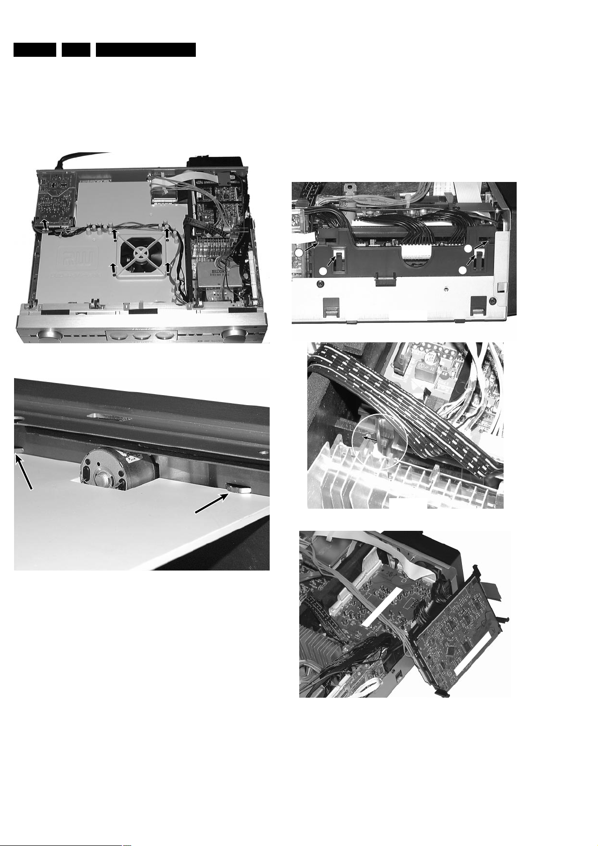
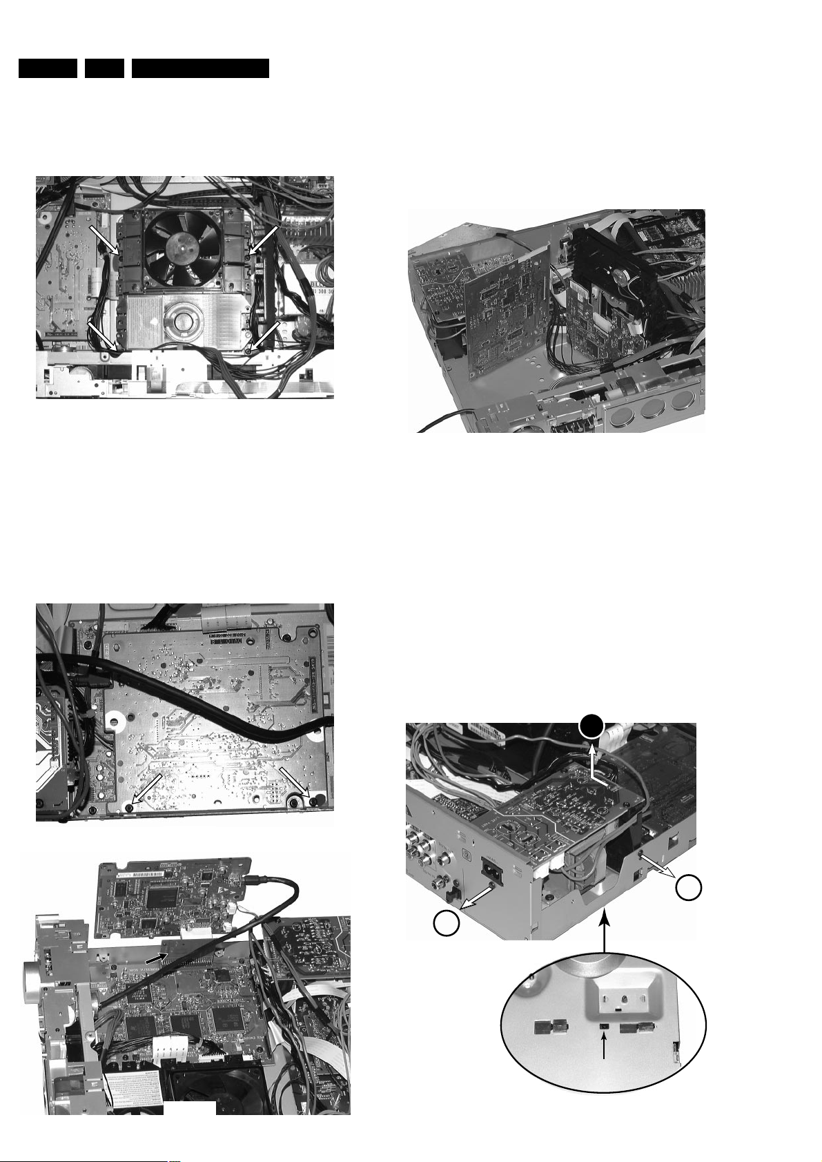
EN 16 4. LX9000R Dismantling Instructions
Removal of
Air guide plate
picture 6
• Remove 5 screws as shown in picture 6.
• Remove cables from the guidings
• Raise airguide plate at the rear to release it from the
guidings at the front side and pull it up.
support on front side
picture 7
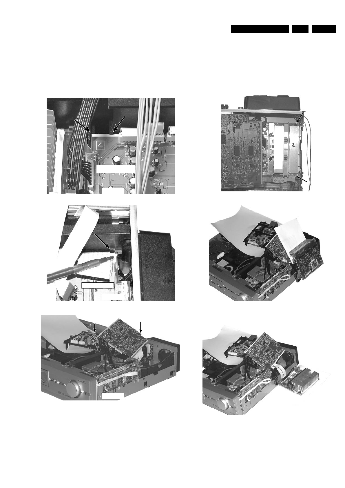
Dismantling the
MDM Board
• Release catches 1 as shown in picture 8.
• Lift MDM Board on the outer side and move it left to
release hooks (at the inner side the support frame is 2x
hooked onto the ASP Board → picture 9 shows hook on
the left side )
• Raise the board up and turn it out to it´s service position →
see picture 10
1
1
2
2
picture 8
MDM Board
picture 9
MDM Board
ASP Board
picture 10
Mounting the
MDM Board
• To mount the MDM board proceed in reverse order to
description above.
• Take care that hooks at the backside (left side) are
positioned correctly and move the board to the outside to
fix the hooks.
• Press the board on the outer side down until catches 1
engage.
EN 174.LX9000RDismantling Instructions
Dismantling the
ASP Board
• Dismantle MDM Board (as described before) first.
• Release catches 2 as shown in picture 8.
• Lift ASP Board on the outer side and pull it out (at the inner
side the board is 2x held by guidings on the thermal partition →
pictures 11 and 12 show the guidings on both sides )
• Raise the board up and turn it, together with the MDM Board,
up to it´s service position → see picture 10
ASP Board
picture 11
ASP Board
picture 12
sheet of paper
for isolation
MDM Board
ASP Board
picture 13
Mounting the
ASP Board
• To mount the ASP board proceed in reverse order to
description above.
• Take care that the board is fed correctly into the guidings
at the backside (left side).
• Press the board on the outer side down until catches
2
engage.
Dismantling the
Amplifier Board
• Dismantle MDM Board and ASP Board (as described before)
first.
• Remove 2 screws as shown in picture 14.
• If necessary, plug cables to loadspeaker socket off.
• Put Amplifier Board in a desired service position as shown in
pictures 15 and 16.
Amplifier Board
picture 14
sheet of paper
for isolation
sheet of paper
for isolation
ASP Board
MDM Board
Amplifier
Board
picture 15
sheet of paper
for isolation
picture 16
EN 18 4. LX9000R Dismantling Instructions
Power Supply secondary
picture 20
picture 21
picture 22
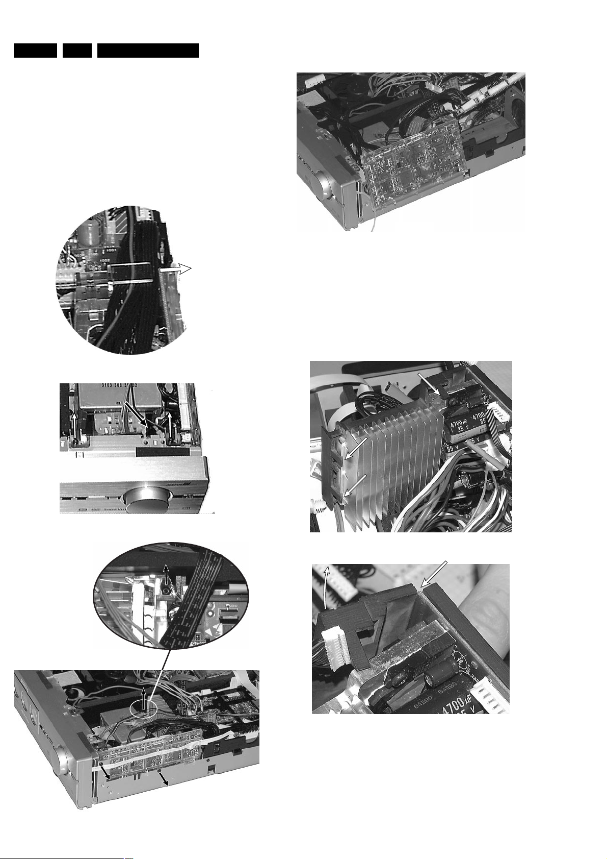
Dismantling the
support frame
of the Power secondary Board
• Dismantle the Power secondary Board as described before.
• Loosen 2 screws from the component side of the board.
• Release 3 catches as shown in picture 21.
• Turn the released part of the support frame away as shown in
picture 22.
The printed circuit board will now automaticly be released on the
rear edges and can be taken off.
Dismantling the
Power secondary Board
• Dismantle MDM- and ASP Board (as described before) first.
• Unplug headphone cable from ASP Board and put it out from the
catches on the Power secondary support frame.
• Release all cables on top → see picture 17
• Release cable to Amplifier Board from the catches on the rear
side of the support frame.
• Remove contact springs and cable ties as shown in picture 18 and
give cables a proper free length for dismantling.
• Remove 3 screws as shown in picture 19
• Raise the board up and put it to a desired service position → see
picture 20
picture 18
cable ties
picture 19
picture 17
move out all wires
EN 194.LX9000RDismantling Instructions
Dismantling the
Front panel assembly
The front panel assy consists of 2 cabinet parts, the ornamental
aluminium front and the plastic front cabinet where the printed circuit
boards and other technical parts are mounted.
Dependent on the location which is wanted to be accessed the front
panel assy can be detached either as complete assy or separated in
aluminium front and plastic front.
To avoid scratches on the ornamental part it is recommended
always to remove the aluminium front first.
Attention:
During dismantling and mounting the front panel assy the
connection pins of the display-motor may touch the metal
cabinet. This short circuit easy causes a destruction of safety
resistor 3550, located on Key Board left. Charged capacitors
deliver sufficient energy even when the set is switched off.
Therefore insolate the motor connections with a piece of
insolating tape before pulling out the front assy!
Dismantling the
ornamental Aluminium Front
• Loosen 8 screws as shown in picture 23 and 24.
• Remove the front flap by loosening the axles first → see picture 25
• Release 7 catches as shown in picture 26 and 27.
• Pull Aluminium Front slightly frontwards.
picture 23
remove 4 screws
picture 24
picture 25
below adhesive tape
Alu Front:
4 x catch on top
picture 26
Alu Front:
4 x catch on bottom
picture 27
display flex foil cable
fixed to cabinet with
double sided adhesive tape
picture 28
• Dismantle Front assembly as described before and put it to
service position as shown in picture 33.
• Release catch as shown in picture 34, move slider left until it is
released and fetch it out.
EN 20 4. LX9000R Dismantling Instructions
key board left
A/V front
connectors
Control board
picture 32
Dismantling the
Plastic Front cabinet
• Loosen 8 screws as shown in picture 23 and 24.
• Plug Firewire cable from DVIO Board off 1 and release all cables
as shown in picture 29 to give them a proper free length for
moving front assy out.
• Release 6 catches as shown in picture 30 and 31.
• Pull Plastic Front slightly frontwards while taking care of the
cables, especially to the flat foil cable 4 on the right side.
• Put front cabinet on the table as shown in picture 32.
1
2
4
3
5
picture 29
Plastic Front: 4 x catch on top
picture 30
Plastic front:
2 x catch on bottom
picture 31
Display connection cable disconnected
picture 33
Service position
Control board / Key Board right
• Dismantle front assy as described before.
• Plug off flex foil cable to display.
• Loosen 1 screw.
• Lift the board on the rear side first in order to release it from the
catches on the front side.
• Turn Control Board up and fix it in the slot as shown in picture 33.
Dismantling the
Slider of the display moving mechanism
picture 34
EN 214.LX9000RDismantling Instructions
Dismantling
Knobs of the Rotary Encoders
• Dismantle ornamental Aluminium Front as described before.
• Turn the knob to a position as shown in picture 35.
• Put a flat screwdriver in between the black plastic part of the rotary
encoder and the transparent plastic part of the knob
→ see picture 35.
• Turn the screwdriver in order to press the transparent part of the
knob over the catch on the encoder → see picture 36.
(this may need some force)
• Repeat 3x, the knobs are caught 4 times.
picture 35
picture 36
Mounting
Knobs onto the Rotary Encoders
• Align guidings and simply push the knob onto the rotary encoder
until the catches engage.
ATTENTION:
Be aware that when the knob has to be replaced by a new one,
pos. 149, 151 and 152 respectively pos. 152, 177 and 178 have to
be ordered.
The 3 parts have to be mounted together by the repair technician.
Dismantling the
Display
1
2
picture 37
picture 38
display flex foil cable
fixed to cabinet with
double sided adhesive tape
picture 39
• Dismantle ornamental Aluminium Front as described before.
• Move the display manually up by means of a screwdriver.
Through a slot on the top side of the front cabinet the gear wheel
of the moving mechanism can be accessed.
Push the gear wheel down in order to dis-engage the motor. Then
turn the wheel clockwise → see picture 37.
Repeat as long as the display has moved completely out.
• Loosen 3 screws on the bottom side of the display.
• Remove the ornamental cover as shown in picture 38.
• Move the display manually down as described before, but turning
the gear wheel counter clockwise.
• Plug off the connection cable from the Control Board and loosen it
carefully from the adhesive tapes → see picture 39.
• Now thread the connection cable out of the plastic front cabinet
and remove display.
EN 22 4. LX9000R Dismantling Instructions
Dismantling the
DVD Basic Engine
• Dismantle Top Cover and Air guide plate as described before.
• Loosen 4 screws as shown in picture 40.
• Plug off cables and fetch the module out.
picture 40
Dismantling the
DVIO Board
• Dismantle Top Cover and Air guide plate as described before.
• Loosen 2 screws as shown in picture 41.
• Disconnect DVIO Board from Digital Board (board to board
connector).
• Take extension board 3104 128 07770 and re-connect DVIO Board
with Digital Board. If necessary, disconnect cable (8006) to Analog
Board.
The DVIO Board is now in a proper service position → see picture 42.
picture 41
DVIO Board
Digital Board
DVIO extension board
3104 128 07770
picture 42
Dismantling the
Digital Board
• Dismantle Top Cover and Air guide plate as described before.
• If necessary, remove DVIO Board first. See description before.
• Loosen 4 screws to dismantle Digital Board.
• To get access to the bottom side, the board can be put to a
service position as shown in picture 43.
Digital Board
DVIO BoarVIO Board
Basic Engine
picture 43
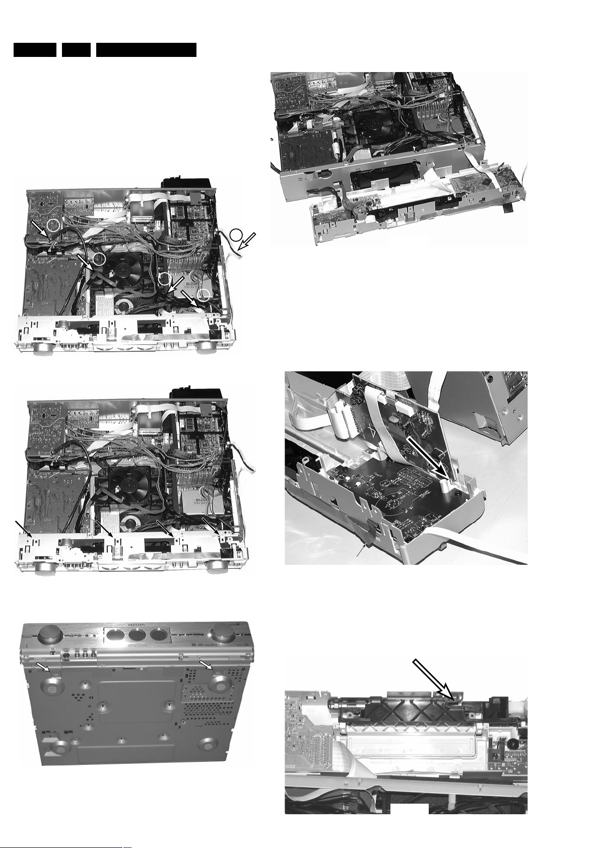
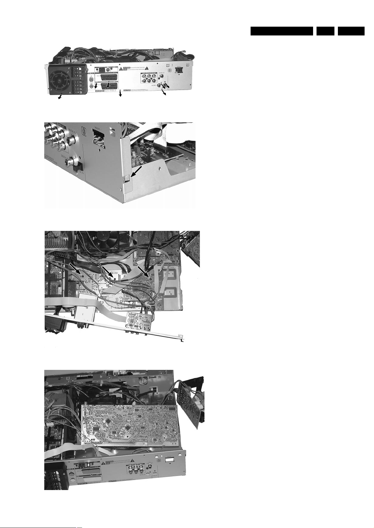
Dismantling the
A/V Board
• Dismantle Top Cover and Air guide plate as described before.
• Dismantle Power primary Board as shown in picture 44.
• Dismantle Standby-transformer and put it together with the Power
primary Board next to the set.
• Loosen 7 screws from rear cabinet as shown inpicture 45.
• Release catches on both sides of the rear cabinet and move it
backwards as far as cable lengts allow → picture 46 shows the
left side catch.
• Loosen 3 screws as shown in picture 47.
• Plug off cables to Auxiliary Board.
• Turn A/V Board to service position as shown in picture 48.
push to release catch
and move left
1
1
2
picture 44
EN 234.LX9000RDismantling Instructions
picture 45
picture 46
picture 47
Analog Board
Power Supply
Primary
picture 48
EN 24 5. LX9000R Service hints
SERVICE TOOLS
TORX T10 screwdriver with shaftlength 150mm.....4822 395 50423
TORX screwdriver set SBC 163.............................4822 295 50145
Audio signal disc SBC 429....................................4822 397 30184
Playability test disc SBC444..................................4822 397 30245
Test disc 5 (disc without errors) +
Test disc 5A (disc with dropout errors, black spots and fingerprints)
SBC 426/426A....................................4822 397 30096
Burn in test disc (65 min. 1kHz signal at -30dB level
without "pause")..................................4822 397 30155
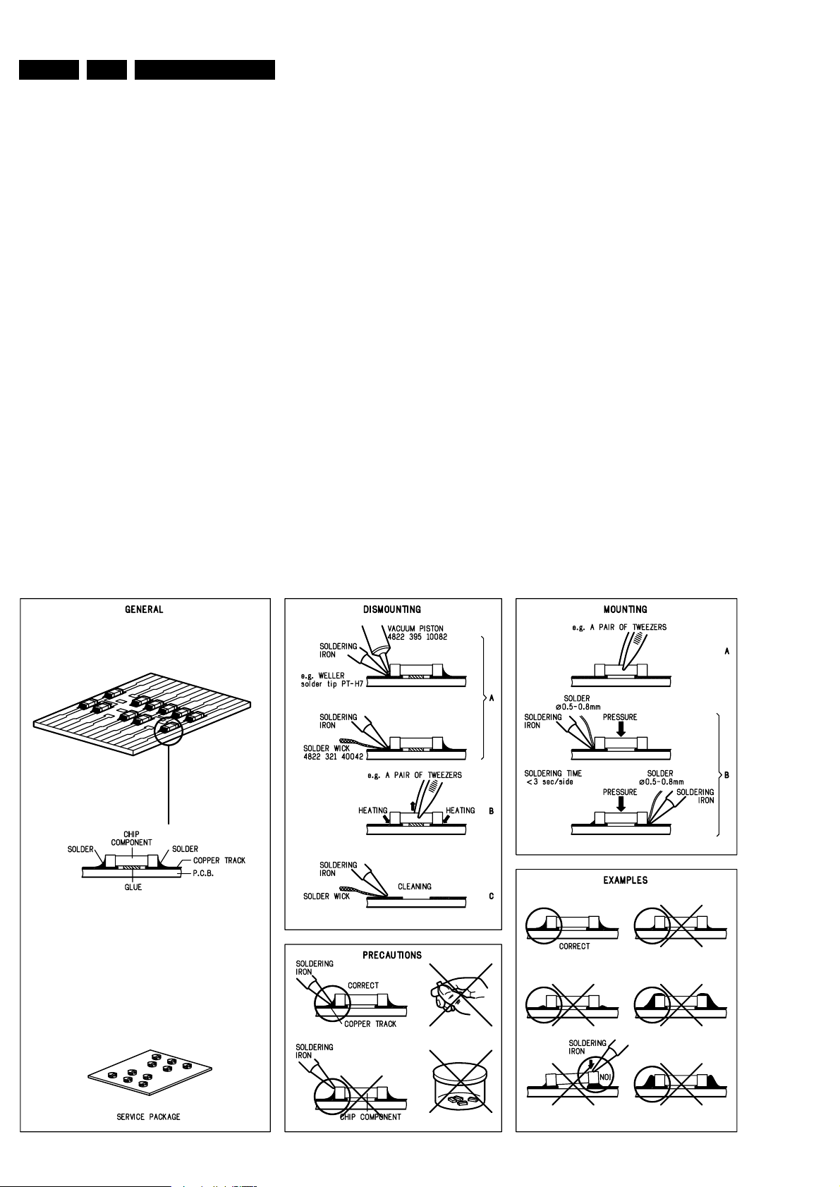
HANDLING CHIP COMPONENTS
TRADE MODE
The sets are equipped with a special TRADE MODE.
This mode blocks the Open/close key on the front panel of
the set to prevent customers from fetching out CDs from
exhibition sets.
The Trade mode can be switched on/off as follows:
Hold Stop & Open/Close keys depressed for more than 5s
(press STOP key first).
→ Display shows for 2s
LOCK TRAY ON else LOCK TRAY OFF
DEMO MODE
The DEMO MODE displays various features of the set and
will start automatically when no key has been pressed for
several minutes or during Standby mode.
The Demo mode can be switched on/off as follows:
1) Switch the set to [Standby]
2) Press the
[STOP] key on the set for more than 5s
→ Display shows
DEMO MODE ON else DEMO MODE OFF
Sub chassis 8 test disc CD....................................7104 099 28362
MPTD printed test disc CVP02.18A.......................7104 099 91691
MPTD printed test disc CVP02.18C ......................7104 099 97941
Burn in test disc DL LVP04.15...............................7104 099 91041
MPTD thin test disc CVP02.60...............................7104 099 97931
NLT 01.00 link test disc DVDROM settings..........7104 099 98502
Blank DVD+RW disc RICOH..................................7104 099 98582
Blank DVD+R disc RICOH......................................7104 099 94001
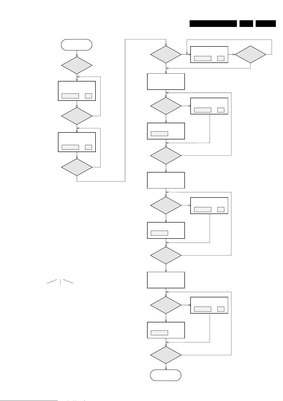
EN 255.LX9000RDiagnostic Software
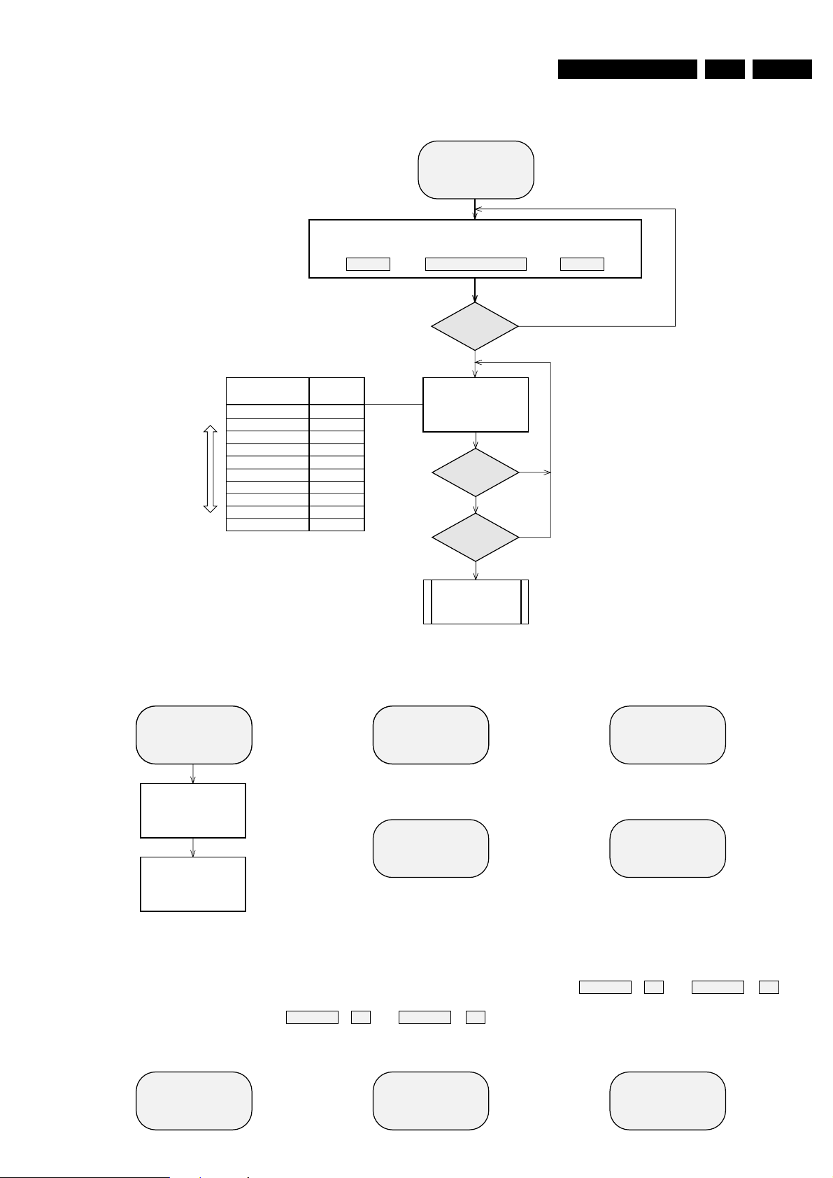
N
Y
SELECT TEST
START TEST
The center display
shows next or previous
test of the test menu.
Quartz test
Temperature test
EEPROM test
EEPROM format
Display test
Key test
AUDIO TUNER test
MDM board test
AMPLIFIER test
LX 9000-R
QUARTZ
NTC
EEPROM
EP FORMAT
DISPLAY
KEY TEST
TUNER
MDM TEST
AMP TEST
S or T
button
pressed?
Y
S or T
button
pressed?
TEST
Display
shows
S
T
Select test
SERVICE TESTS
APPARATUS
servtest LX9000R sh 1, 210703
N
N
Y
Start
actual selected test.
For detailed description of the various tests
see next pages.
PLAY
button
pressed?
Test menu
SERVICE TESTPROGRAM
OVERVIEW ALL TESTS
VXX
SV
*
To leave Service Testprogram plug mains cord off.
*
In the main menu the sound settings (volume, ...)
and tray work as in normal mode.
stands for Service mode
To check versions of the
DVD+RW software use OSD.
stands for Version number
of the software used in the
Front (Display) µP.
To enter Service
Testprogram hold
Open/Close
button
depressed while
plugging mainscord in.
LX 9000-R V-XX
The right hand display
shows the version number
of the front µP - software.
SV
The left hand display
shows.
The center display
shows.
DVD PLAYER TEST
(script)
To start the DVD Player test
hold
Open/Close & PLAY
buttons
depressed
while plugging mainscord in.
DIGITAL BOARD &
A/V BOARD
TEST
BASIC ENGINE
TEST
For detailed description of the
DVD player scripts see page 31 ff.
For detailed description of the
End-User Diagnostic see page x ff.
END-USER DIAGNOSTICS
(DVD+RW module)
To enter
END-USER DIAGNOSTICS
hold
PLAY
button depressed
while plugging mainscord in.
VIRGIN MODE
(DVD+RW module)
To reset the set to
Virgin Mode
hold
STANDBY
button
depressed
while plugging mainscord in.
TRADE MODE
To switch Trade Mode
on/off
hold
STOP & Open/Close
buttons depressed
for more than 5s.
DEMO MODE
Switch set to Standby first.
To switch Demo Mode
on/off
hold
STOP
button depressed
for more than 5s
.
TOGGLE VIDEO MODE
To toggle Video Mode
(interlace/progressive scan)
hold
STOP
button depressed
while plugging mainscord in.
for USA version onlyfor USA version only
FORCED DOWNLOAD
OF OLDER SOFTWARE VERSION
To enable loading of
an older software version hold
RECORD & PLAY
buttons
depressed
while plugging mainscord in.
TOGGLE
MODULATOR CHANNEL
To toggle Modulator Channel
(channel 3/4) hold
RECORD
button depressed
while plugging mainscord in.
TRADE MODE
The sets are equipped with a special TRADE MODE.
This mode blocks the Open/Close-key on the front panel
of the set to prevent customers from fetching out discs
from exhibition sets.
The tray can only be opened with the remote control.
The Trade mode can be switched on/off as follows:
Hold the
STOP & Open/Close
keys depressed for
more than 5s (press
STOP
key first).
→ Display shows for 2s
LOCK TRAY ON else LOCK TRAY OFF
DEMO MODE
The DEMO MODE displays various features of the set
and will start automatically when no key has been
pressed for several minutes or during Standby mode.
The Demo mode can be switched on/off as follows:
1) Switch the set to [Standby]
2) Press the
[STOP] key on the set for more than 5s
→ Display shows
DEMO MODE ON else DEMO MODE OFF
EN 26 5. LX9000R Diagnostic Software
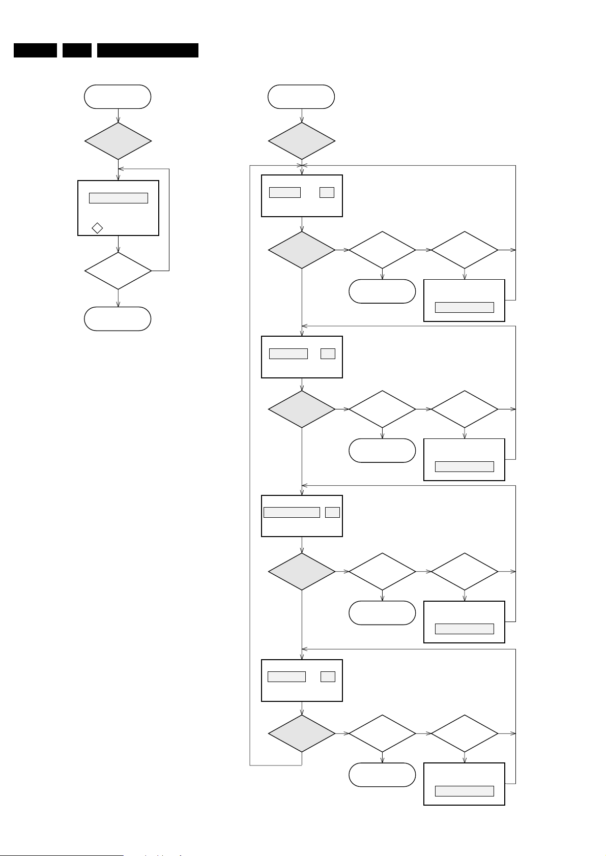
servtest LX9000R sh 2, 040503
Y
QUARTZ TEST
Display shows
5859,375±175Hz can be
measurured
on
(pin 18 of µP).
STOP
button
pressed?
N
Y
Press
PLAY
button.
Tact frequency µP
(divided 12MHz)
f
0
12 MHZ
Back to main menu.
The Quartz test allows a quick check of the oscillator of the
Front µP without any influence to the oscillator circuitry by the
test equipment.
The factory can check if the correct quartz has been
assembled.
A 50% duty pulse of the divided oscillator frequency is put on
pin 18 of the µP (MDM_SCL).
To avoid dismantling of the front cabinet the test signal can best
be measured on pin 9 of 1802, located on the MDM board.
TEMPERATURE TEST
The temperature test is used to check the NTC resistors which
measure various temperatures to control the speed of the basic
engine fan and the set fan.
NTC Front: sensor for ambient temperature, located on
Key board left.
Controls the fan of the basic engine.
NTC Supply: sensor for the temperature of the heatsink on
the Power Secondary board.
NTC Amp(lifier): sensor for the temperature of the heatsink on
the Power Amplifier board.
NTC Trafo: sensor for the temperature of the main
transformer.
The signals NTC Supply, NTC Amp and NTC Trafo are
compared with a special algorithm and result in the control
signals SetFan1 and SetFan2 which control the speed of the
set fan.
In each test step of the temperature test the speed of the set
fan can be set in four steps.
FRONT XX
Display shows
XX = value in ˚C
Display shows
XX = value in ˚C
S or T
button
pressed?
N
YY
Switch speed of set fan
to next/previous step.
Display shows
for 2s.
x= 1, 2, 3, 4
x= 1, 2, 3, 4
x= 1, 2, 3, 4
x= 1, 2, 3, 4
FAN SPD X
Press
PLAY
button.
TEMPERATURE
TEST
NN
Y
PLAY
button
pressed?
Display shows
XX = value in ˚C
N
Y
PLAY
button
pressed?
Display shows
XX = value in ˚C
N
Y
PLAY
button
pressed?
N
Y
PLAY
button
pressed?
Back to main menu.
STOP
button
pressed?
S or T
button
pressed?
N
YY
Switch speed of set fan
to next/previous step.
Display shows
for 2s.
FAN SPD X
N
Back to main menu.
STOP
button
pressed?
S or T
button
pressed?
N
YY
Switch speed of set fan
to next/previous step.
Display shows
for 2s.
FAN SPD X
N
Back to main menu.
STOP
button
pressed?
S or T
button
pressed?
N
YY
Switch speed of set fan
to next/previous step.
Display shows
for 2s.
FAN SPD X
N
Back to main menu.
STOP
button
pressed?
SUPPLY XX
AMPLIFIER XX
TRAFO XX
Press
S or T
button
and select
QUARZ
Press
S or T
button
and select
NTC
EN 275.LX9000RDiagnostic Software
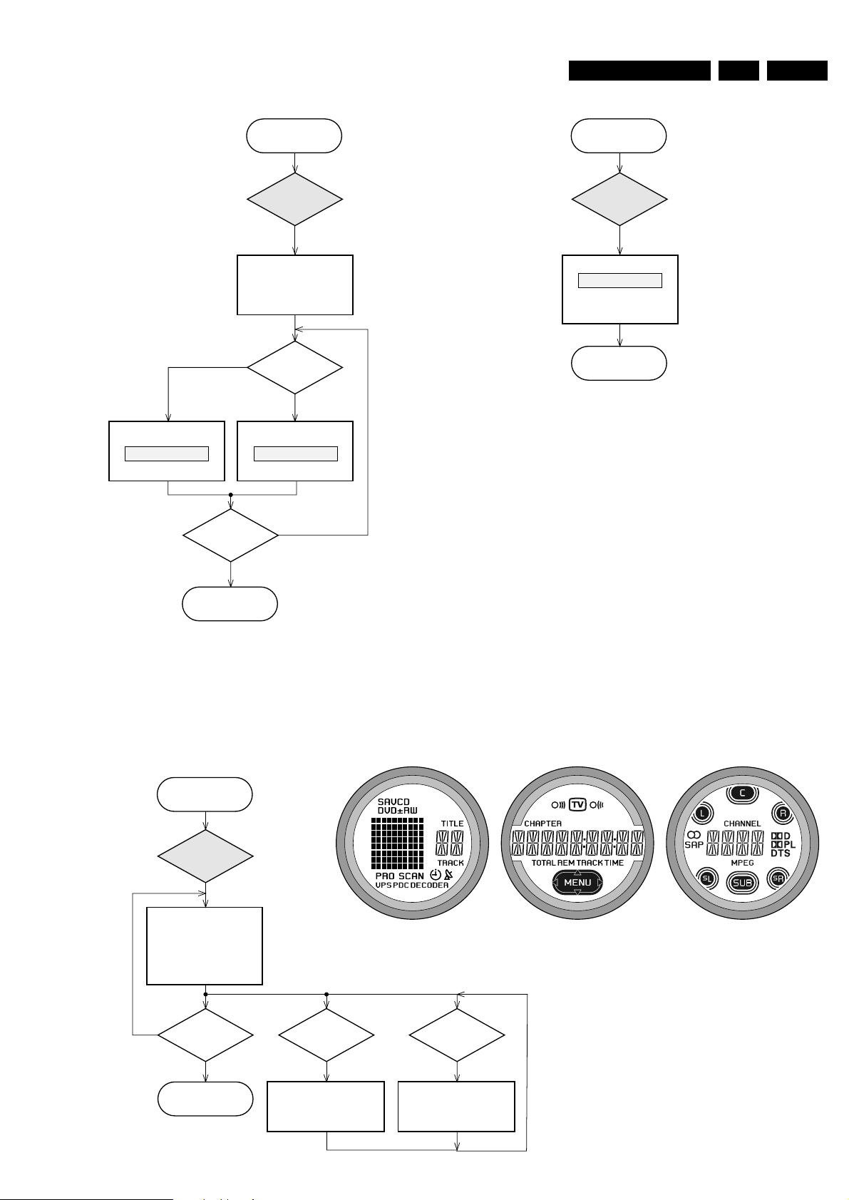
servtest LX9000R sh 3, 060503
Press
PLAY
button.
STOP
button
pressed?
T
button
pressed?
N
Y
Y
Display shows
all
segments and flags
for checking open circuits.
see figure 1
All LEDs are switched off.
Backlight is switched on.
Switch intensity of the
backlight diodes to next step.
(toggles backlight intensity
to
half / off / full
intensity)
Y
DISPLAY TEST
Back to main menu.
fig. 1
S
button
pressed?
Switch on LEDs in following
sequence:
Standby, Instant Record,
Record, off
Y
PASS
Y
EEPROM TEST
Display shows
ERR
Display shows
Test pattern is written to
address 1
and
read back again
STOP
button
pressed?
Test ok?
N
Y
N
Y
Press
PLAY
button.
Back to main menu.
Back to main menu.
Y
FORMAT EEPROM
Display shows
for 2s.
EEPROM is cleared and
default values are stored.
NEW
Press
PLAY
button.
The test checks writing and reading of data to the EEPROM.
A test pattern is written to the first location in the EEPROM.
PASS is displayed when the test pattern is read back correctly,
else ERR.
Each software module using the EEPROM is forced to write the
default values in its part of the EEPROM.
This test should only be used to clear the EEPROM in case
of a µP-"hangup".
The DISPLAY test is intended to check the driver circuits,
the display module and the LEDs for open- or shortcircuits.
The LEDs
Standby, Instant Record
and
Record
can be
switched on/off separately.
The intensity of the backlight LEDs can be switched in 3
steps: full, half, off
Press
S or T
button
and select
EEPROM
Press
S or T
button
and select
DISPLAY
Press
S or T
button
and select
EP FORMAT
EN 28 5. LX9000R Diagnostic Software
servtest LX9000R sh 4, 100503
Y
AUDIO TUNER
TEST
Press
PLAY
button.
N
Y
EUR USA
Exit
Service Testprogram.
Display shows
version of the Audio tuner
as long as any key will
be pressed.
else
POWER
switched off?
Service Preset-frequencies
acc. table 2 are copied
to the RAM.
Tuner is normal working
except for the
PROGRAM
and
AUTOPROGRAM
functions. When a station is
received the radio antenna
symbol will light up.
When RDS data are
received a dot will be shown
additionally.
EUROPE
FM/MW
USA
FM/AM
table 2
table 3
REGION
Key
NEXT T
PREV
S
STOP 9
PLAY 2
OPEN/CLOSE
manual tuning + auto search
manual tuning + auto search
preset down
preset up
band switch (FM stereo, FM mono, AM)
Function
PRESET
1
2
3
4
5
6
7
8
87,5 MHz
The Audio tuner test is intended to read out the tuner version selected by the front µP.
The correct tuner version is defined by the version detection resistor 3444 mounted on
the Front - Control board. 3444 mounted = USA version without RDS.
The stored preset frequencies serve as provision for other tuner modules only.
108 MHz
531 kHz
1602 kHz
558 kHz
1494 kHz
98 MHz
87,5 MHz
108 MHz
560 kHz
1500 kHz
98 MHz
--- ---
530 kHz
1700 kHz
/22/25/29 /37
SERVICE PRESET FREQUENCIES
USAEUR
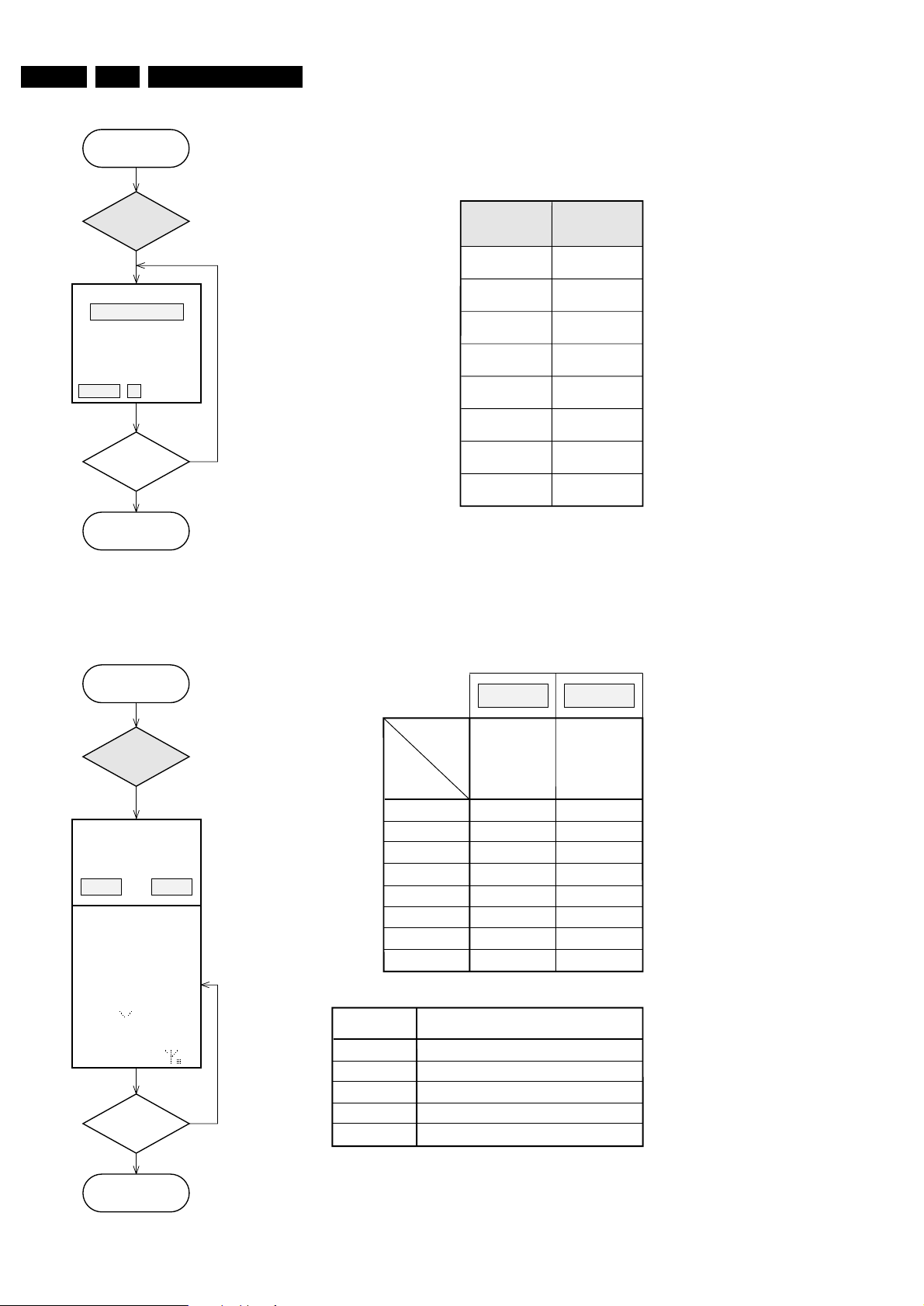
Y
KEY TEST
Press
PLAY
button.
STOP
button
pressed?
N
Y
KEY --
Back to main menu.
X=5 stands for RC5 code
X=6 stands for RC6 code
CC stands for the command code
SS stands for the system code
NEXT T
PREVIOUS S
KEY KEY CODE
2
3
4 (exit)
5
6
7
8
SURROUND
RECORD
STOP
PLAY/PAUSE
STANDBY/ON 1
OPEN/CLOSE
KEY CODES
table 1
Display shows
Numbers acc. table 1
are indicated as long as a
button is held depressed.
If a button is pressed
on the Remote Control
RCX CC SS is shown.
Press
S or T
button
and select
KEY TEST
Press
S or T button
and select
TUNER
EN 295.LX9000RDiagnostic Software
servtest LX9000R sh 5, 140603
MDM SW XX
Display shows software
version of µP 7711.
DSP SW XX
Display shows software
version of DSP 7705.
MDM ER
Display shows
Press
PLAY
button.
MDM TEST
N
Y
PLAY
button
pressed?
N
Y
PLAY
button
pressed?
N
Y
PLAY
button
pressed?
Set MDM module
in service mode and
select Analog Input
from Line 1.
Set MDM module
in service mode and
select Digital Input.
Y
N
N
MDM error
?
Y
MDM error
?
N
Y
PLAY
button
pressed?
bbb
LIN ER
Display shows
bbb
LIN 1
Display shows
DIG
Display shows
ERRORS:
bbb indicates the kind of an error.
DSP
error
SRAM
error
EEPROM
error
OPT
Display shows
N
Y
MDM error
?
N
Y
PLAY
button
pressed?
DIG ER
Display shows
bbb
Set MDM module
in service mode and
select Optical Input.
N
Y
MDM error
?
N
Y
PLAY
button
pressed?
OPT ER
Display shows
bbb
Back to main menu.
By entering the MDM test the user settings are reset to the
initial values:
Volume: 10 (-33dB)
Bass, Treble: flat
Loudness: off
Clear Voice: off
Bass ALC: on
Delta volume all loudspeakers: 0dB
Note: The MDM test produces output on 6 channels.
During the test manual setting of the sound
parameters is possible.
b b b
e.g. 001 means DSP error
101 means DSP plus EEPROM error
Press
S or T button
and select
MTM TEST
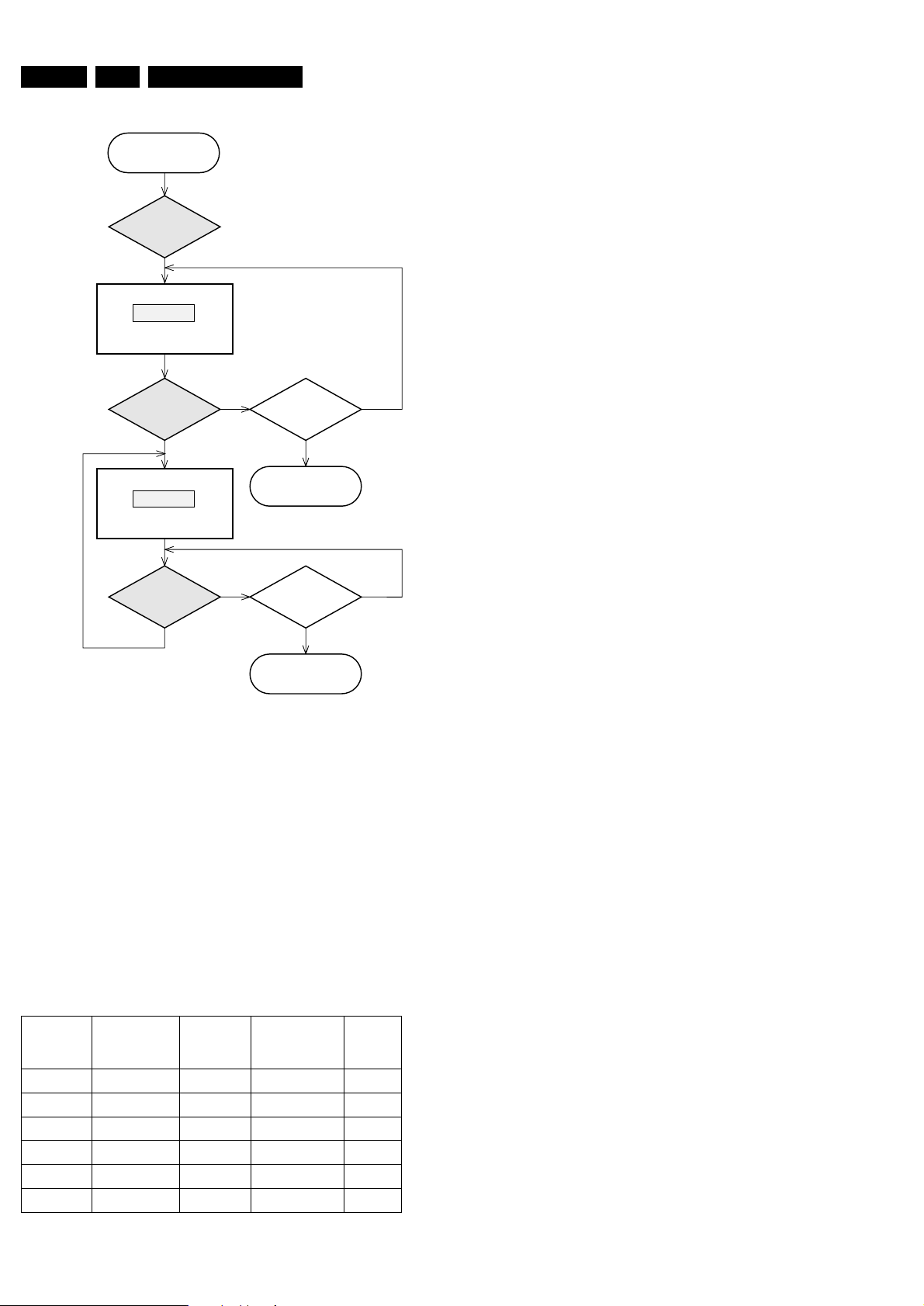
EN 30 5. LX9000R Diagnostic Software
servtest LX9000R sh 6, 100503
AMP 1
Center display shows
Sound parameters are set
acc. table 4
Display shows next test
Sound parameters are set
acc. table 4
Press
PLAY
button.
AMPLIFIER TEST
N
Y
PLAY
button
pressed?
NN
YY
PLAY
button
pressed?
STOP
button
pressed?
Back to main menu.
N
Y
STOP
button
pressed?
Back to main menu.
X
= 2, 3, 4, 5, 6,1
Test mode
AMP 1
AMP 2
AMP 3
AMP 4
AMP 5
AMP 6
Line in 1
Line in 2
Ext. 1
Ext. 2
Line in 1
Line in 2
off
off
off
off
on
on
off
off
off
off
off
on
off
off
off
off
off
on
Audio INPUT Bass ALC
MUTE
(Headhone and
Loudspeakers)
MUTE
Line out
The Amplifier test is intended for testing the analog modes of
the amplifier and the sound processor settings.
By entering the MDM test the user settings are reset to the initial
values:
Volume: 10 (-33dB)
Bass, Treble: flat
Loudness: off
Clear Voice: off
Bass ALC: on
Delta volume all loudspeakers: 0dB
Note: The AMPLIFIER test produces output on 6 channels.
During the test manual setting of the sound
parameters is possible.
table 4
AMP X
Press
S or T button
and select
a
AMP TEST
 Loading...