

Page 1
Quick installation guide
Philips InteGrade LED engine system
for indoor environments and
refrigerated cabinets (-30 to +30 °C / -22 to +86 °F)
June 2013
Page 2

2
Please take the time to read this installation guide before you install this Philips LED product and driver.
The guide contains important information regarding installation and operation.
Warranty
Warranty only applies when the appropriate Philips LED driver and Philips cabling (as described in this guide and leaets) are used.
Please visit our website www.philips.com/ledrefrigeration or contact your local sales ofce for more information.
Warnings
• The installation guide does not supersede local or (inter)national regulations for electrical installations.
• This Philips LED product and LED driver must be installed by a professional electrician in accordance with the applicable and
appropriate electrical codes and the instructions provided by Philips.
• Please note that the driver should be built into an enclosure (Tcase max. 70 °C / 158 °F).
• This Philips LED product is designed to be connected to a circuit from a class 2 power source (Philips Xitanium LED power driver)
with energy-limited supply.
• This is a 24 V DC product.
• Do not connect this LED product to mains voltages.
• To allow for variance in the installation, it is not recommended to load the power driver beyond 90% of its rated maximum power.
The energy consumption of the engine is a nominal value, with an estimated 20% deviation.
• Before installation, maintenance or cleaning, always rst switch off or disconnect the power and follow the appropriate safety
procedures.
• Before removing any lens covers or uorescent lamps, always rst switch off or disconnect the mains power to the lighting system.
• Take care not to damage the existing (heating) wiring if the LED product is installed in a freezer.
• Do not use tape to x this InteGrade LED product or LED prole in position; please use the appropriate mounting clips.
• Please note that the colors of the wires in existing designs, such as refrigeration systems or cabinets, may differ. The position of the
(original) ballast may also differ.
• Do not make sharp bends with electrical wires.
• Due to the variety of designs and brands in which the Philips LED products can be installed, you may need to use customized mounting
accessories to t the specic design you are using. If you require further support, please contact your local Philips sales organization.
• To prevent unwanted tripping caused by the inrush current of the LED driver, an MCB (mini circuit breaker) / fuse (slow blow) of
at least 6 A must be installed.
• Philips advises using a zero-crossing/switching solid-state relay to reduce the inrush current peak.
• This product is designed for damp and dry locations only.
Cleaning
• Use a damp cloth and a mild cleaning agent. Do not wipe the LED product with a dirty or very wet dishcloth or towel
because they may leave residue that can damage the LED product.
• Do not use abrasive cleaners, scouring pads, bleach or cleaners containing chlorine because they can scratch and damage
the LED product.
Important
NL
DE
FR
IT
ES
www.philips.com/ledrefrigeration
Installation instructions
Page 3
3
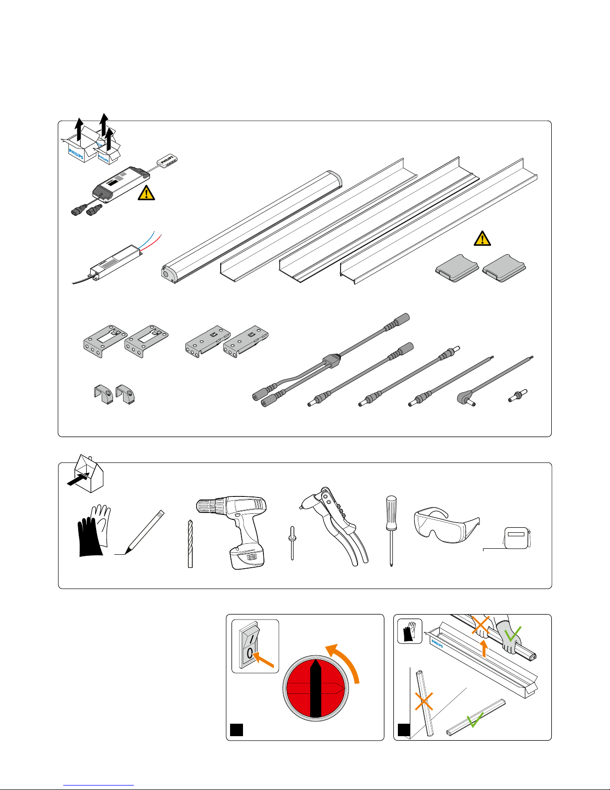
Philips Xitanium
LED Power Driver
(20 or 80 W 24 Vdc)
LED Power Driver 75 W-24 V PP ltG
-C8 plug
-N plug
RH<90%
InteGrade
cable angle
InteGrade
cable
InteGrade LED
engine
InteGrade
profile
InteGrade
profile (M style)
InteGrade
profile (F style)
InteGrade
connector
InteGrade engine
lock inline
InteGrade
mounting clip shelf arm
InteGrade
extension cable
InteGrade
Y cable
InteGrade
spacer cable
InteGrade
mounting clip under shelf
InteGrade magnet
for M style profile
RH<90%
2.9 mm (1/8 inch) Phillips H0 screw driver
Products and tools
OFF
ON
1
2
Start
Page 4

4
1
4
3
3
2
2
1
1
2
1
2
1
2
1
2
Phillips HO
screwdriver/
torque 10
to 15 cNm
Connecting the LED InteGrade engines
in the prole
3
Page 5

5
50 cm (20 inch)
2
1
3
4
1
2
1
2
1
2
3
4
5
1
2
3
4
1
2
Installation examples with various
InteGrade mounting clips and proles
4A
4E
4B
min. 2
RH<90%
1
2
4C
4D
When using the 2 m (79 inch) F style profile please ensure
it is properly fastened. Engines can then be placed in infinite
lines BUT should be powered in accordance with the
instructions in this guide. Each powered section should be
locked in place by two "lock in-line's" to ensure proper
contacting of the engines and power cables.
Never attach separate profiles
beneath individual
connected engines.
Attach a single profile beneath
two connected engines
in order to ensure
stability.
Page 6

6
Tcase max. 70 °C / 158 °F
80W
Power driver and wiring
• To allow for variance in the installation, it is not recommended to load the power driver
beyond 90% of it’s rated maximum power
- Xitanium LED driver 20 W (logistic code 929000654006) max 18 W
- Xitanium LED driver 80 W (logistic code 929000653906) max 72 W
- Xitanium LED driver 75 W (logistic code 929000869713) max 70 W
• The maximum number of engines that can be connected depends
on the ambient temperature of the InteGrade engine in the application
(< 10 °C and > 10 °C / < 50 °F and > 50 °F)
• Use Philips InteGrade LED power cable of 1 m (39 inch) or 2.5 m (98 inch)
• If InteGrade power cables are extended, only use 0.75 mm2 (AWG 18) or
thicker cable uptil a length of max 10 m (32 feet) between driver and Philips LED power cable
• If you wish to make any other conguration, please contact Philips.
Parallel connection
• You can make any combination of 140 and 575 mm (6 and 23 inch) engines but:
- do not exceed the maximum total load on one driver and
- stay within the boundaries of the maximum load allowed for series connection,
see tables below!
The 20 W and 80 W driver
should be built-in.
Series connection with Xitanium 20 W driver
Xitanium 20 W driver
(logistic code 929000654006)
Maximum quantity of InteGrade engines
Engine wattage (watt) 1 2 5 10
Engine Length (mm) 140 140 575 575
< 10 °C / < 50 °F 14 7 3 1
> 10 °C / > 50 °F 14 7 3 1
Series connection with Xitanium 75 W plug and play driver
Xitanium 75 W driver
(logistic code 929000869713)
Maximum quantity of InteGrade engines
Engine wattage (watt) 1 2 5 10
Engine Length (mm) 140 140 575 575
< 10 °C / < 50 °F 30 15 8 4
> 10 °C / > 50 °F 45 20 12 5
Series connection with Xitanium 80 W driver
Xitanium 80 W driver
(logistic code 929000653906)
Maximum quantity of InteGrade engines
Engine wattage (watt) 1 2 5 10
Engine Length (mm) 140 140 575 575
< 10 °C / < 50 °F 30 15 8 4
> 10 °C / > 50 °F 45 20 12 5
Page 7

7
Philips LED
Power Driver
80 W 24V DC
0.75 mm
2
(AWG 18)
max. 10 m
(32 feet)
driver cable
approx 0.3 m
(12 inch)
Philips InteGrade
cable per string
together max. 2.5 m
(98 inch)
A
B
Philips LED
Power Driver
20 W 24V DC
0.75 mm
2
(AWG 18)
max. 10 m
(32 feet)
driver cable
approx 0.3 m
(12 inch)
Philips InteGrade
cable per string
together max. 2.5 m
(98 inch)
A
B
Example parallel connections (more strings) Example series connections (one string)
InteGrade LED engine 140 mm (6") InteGrade LED engine 575 mm (23") 1 string
Wiring diagram with Philips InteGrade LED engines
Page 8

©2013 Royal Philips Electronics
All rights reserved.
Form No. 3222 635 67102 US -30-+30
LE-6590-A 06/2013
www.philips.com/oem
www.philips.com/ledrefrigeration
www.philips.com/ledmodulesna / NA Customer Support/Technical Service: Tel. (1)800-372-3331
 Loading...