

Philips HR7725 Service Manual
Service
Information
!
Philips Domestic Appliances and Personal Care
Food processor
HR 7725
HR 7727
PRODUCT INFORMATION
The food processors are equipped with mechanical and
thermal safety switches.
Motor power : 600 W
Voltage : 220-240 V ; 50-60 Hz
: 120 V ; 50-60 Hz
Cordset : 125 cm
Speed settings : HR 7725 2 speeds + pulse
: HR 7727 variable speeds + pulse
Bowl capacity : 2.5 l dry ingredients
1.0 l liquids
Blender capacity : 1.0 l liquids
2.0 l (max. contents)
Speeds unloaded : blender drive shaft 17000 rpm (max)
acc. drive shaft 2150 rpm (max)
acc. drive shaft 1400 rpm (min)
Weight in fancy box : HR 7725 - 5100 g
HR 7727 - 5700 g
Dimensions (lxwxh) :HR7725 - 410 x 273 x 375
HR 7727 - 410 x 273 x 510
Automatic resettable cut-out (part of item 7)
To prevent damage due to overheating, the appliance
has been equipped with an automatic cut-out system.
This system will automatically cut off the power supply
when the appliance overheats.
If the appliance suddenly stops running:
−
Unplug the appliance
−
Set the knob to position 0
−
Let the appliance cool down for 15 minutes
−
Plug the appliance in again
−
Switch the appliance on again
MSH coding 8837 725 00000
Safety lock (item 1)
Place the lid on the bowl in the right position.
The appliance will only function if the arrow on the
applinace is directly opposite the mark on the lid of the
food processor bowl and the same holds for the other
accessoires. The built-in safety lock will now be deblocked
and you can turn the appliance on.
Note that if both the blender jar and the bowl have been
correctly mounted, only the blender will function.
Important:
If the appliance is used without the blender jar, the
appliance will not function if the screw cap has not been
screwed onto the attaching hole for the blender.
8837 727 00000
PublishedbyPhilips Domestic Appliances and Personal Care Printed in the Netherlands
4822 729 21951
98/04
PCS 98 486
©
Copyrightreserved Subjectto modification
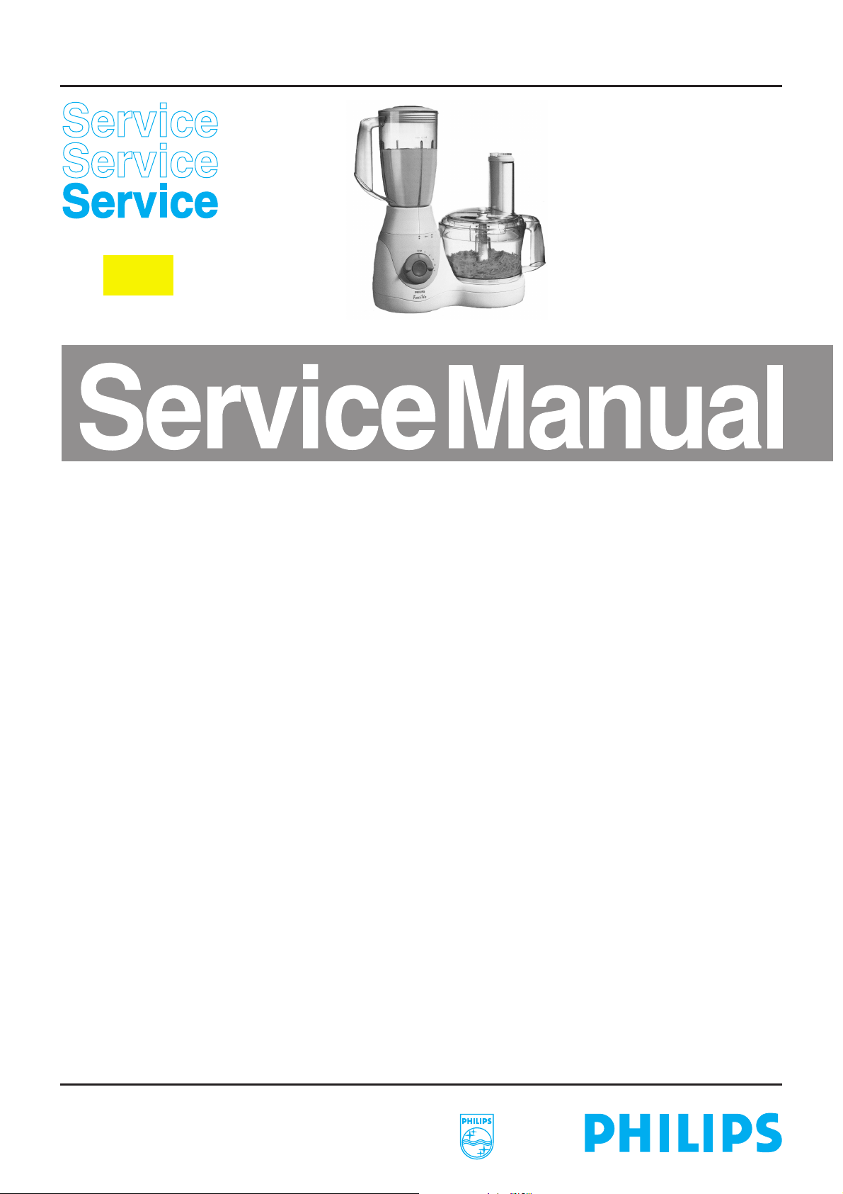
SERVICE INFORMATION
HR 7725
−
A separate drawing shows how to disconnect the
speed selection knob.
HR 7727
−
First remove the pulse button (marked “M”) as shown
in the figure. Then unlock two snap connections to
remove the variomatic knob from the top housing.
2
− HR 7727
Remove the Poti gear (item 32) by turning it clockwise
until the arrows face each other.
The blender coupling on the motor shaft has been
−
provided with the customary left-hand thread.
The drive coupling (item 11) can be detached by
means of a hammer and a screwdriver. Strike the
screwdriver with a short sharp blow and remove the
drive coupling. Or block the acc. drive wheel (item 23)
and thereby the rotor shaft, by sticking a pin through
the hole (5 mm dia.) in the bottom plate.
The top housing (item 29) can be removed by
−
detaching the snap connections by sticking a pin (or a
screwdriver) through the small round holes (3 mm dia.)
in the bottom plate (item 27) and the housing (item 12).
The arrows in the drawing show the locations of the
holes.
In order to replace the speed selection or variomatic
−
knob, the locking lever (item 33) must be placed in its
lowest position.
The minimum speed of the HR 7727 can be set when
−
the pulse button (the button marked with an “M”) is not
mounted. The minimum speed (rpm) has been
correctly set if the motor starts automatically and
1
continues to run smoothly with the variomatic knob and
the adjustable potentiometer in the lowest setting.
The accessory drive shaft (item 15) has a locking piece
−
(item 14).
The assembly of the accessories depends on the
−
1
national version.
− For specific versions, the component configuration may
differ from the one shown on the exploded view.
However, the actual components can be distinguished
by their code numbers.
−
Make sure that all functions, including the safety
devices, are working correctly after you have
completed the repair.
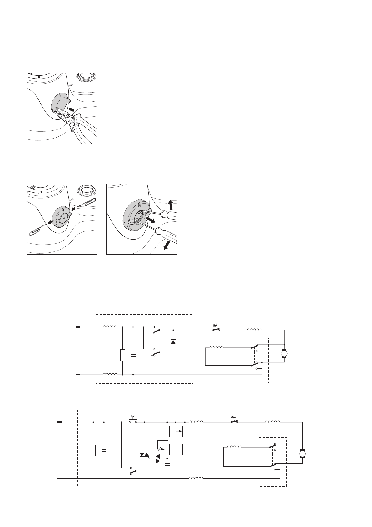
MAINS
MAINS
brown
blueRN
brown
blueRN
R1
470k
L2
470k
L1
C1
R1
Pulse
On/Off
C1
Q2
Speed High
and Pulse
Speed Low
R4
470k
Q1
M1
D1
1N5406
HR 7725
R5
1M
C2
68nF
HR 7727
N1
R2
1M
R3
27k
red
F2
brown
blackF1F2
violet N
L3
M
red
F2
L1
N1
F1
BF
B
Change-over switch
in braking position
brown
blackF1F2
violet N
Change-over switch
in braking position
white
yellow
F1
DAP0535
BF
B
Rotor
white
Rotor
yellow
DAP0536
 Loading...