

Page 1

Boiler steam iron Provapor Azur
GC6063
Philips Domestic Appliances and Personal Care
Service Manual
PRODUCT INFORMATION
Features
Iron
- Careeza soleplate
- Max steam output 70 grams/min
- Cord length 1.9 m
Boiler
- Inox boiler
- Capacity 1 litre
- Stainless steel tray assy
- Ergonomic backrest
Safety Information
- This product meets the requirements regarding
interference suppression on radio and TV.
- After the product has been repaired, it should function
properly and has to meet the safety requirements as
officially laid down at this moment.
TECHNICAL INFORMATION
Voltage : 220 - 240 V
Frequency : 50 - 60 Hz
Power consumption : Iron : 800 W
Boiler : 1200 W
Pressure : 2.5 bar
Dimension (F-box) : 41 x 38 x 20 cm
Weight : 3850 grams
Water advice : Suitable for tap water use. However if
the tap water in your area is very hard,
we advise you to mix it with a equal
portion of distilled water or to use
distilled water only.
Soleplate
Careeza is a multi layer chemical substance that gives an
excellent gliding over various fabrics and better care for the
garments.
Published by Philips Domestic Appliances and Personal Care Printed in the Netherlands © Copyright reserved Subject to modification
03/08
Page 2
DISASSEMBLY ADVICE - IRON
GC6063
REPLACE DIAL 1
REPLACE BACKPLATE 2
disassemble DIAL 1
remove screw A
remove connection
remove hose
REPLACE INLAY 3
IRON LAMP 4
MICRO SWITCH 5
REPLACE IRON HANDLE 6
disassemble DIAL 1
remove screw A
remove connection
remove hose
disassemble BACKPLATE 2
disassemble INLAY 3
IRON LAMP 4
MICRO SWITCH 5
remove screw B (3x)
REPLACE
INTERMEDIATE CABLE 7
SWIVEL 8
THERMOSTAT BUSH 9
disassemble DIAL 1
remove screw A
remove connection
remove hose
disassemble BACKPLATE 2
disassemble INLAY 3
IRON LAMP 4
MICRO SWITCH 5
remove screw B (3x)
disassemble IRON HANDLE 6
REPLACE IRON SKIRT 10
SOLEPLATE UNIT 11
disassemble DIAL 1
remove screw A
remove connection
remove hose
disassemble BACKPLATE 2
disassemble INLAY 3
IRON LAMP 4
MICRO SWITCH 5
remove screw B (3x)
disassemble IRON HANDLE 6
disassemble INTERMEDIATE
CABLE 7
SWIVEL 8
THERMOSTAT
BUSH 9
remove screw C (3x)
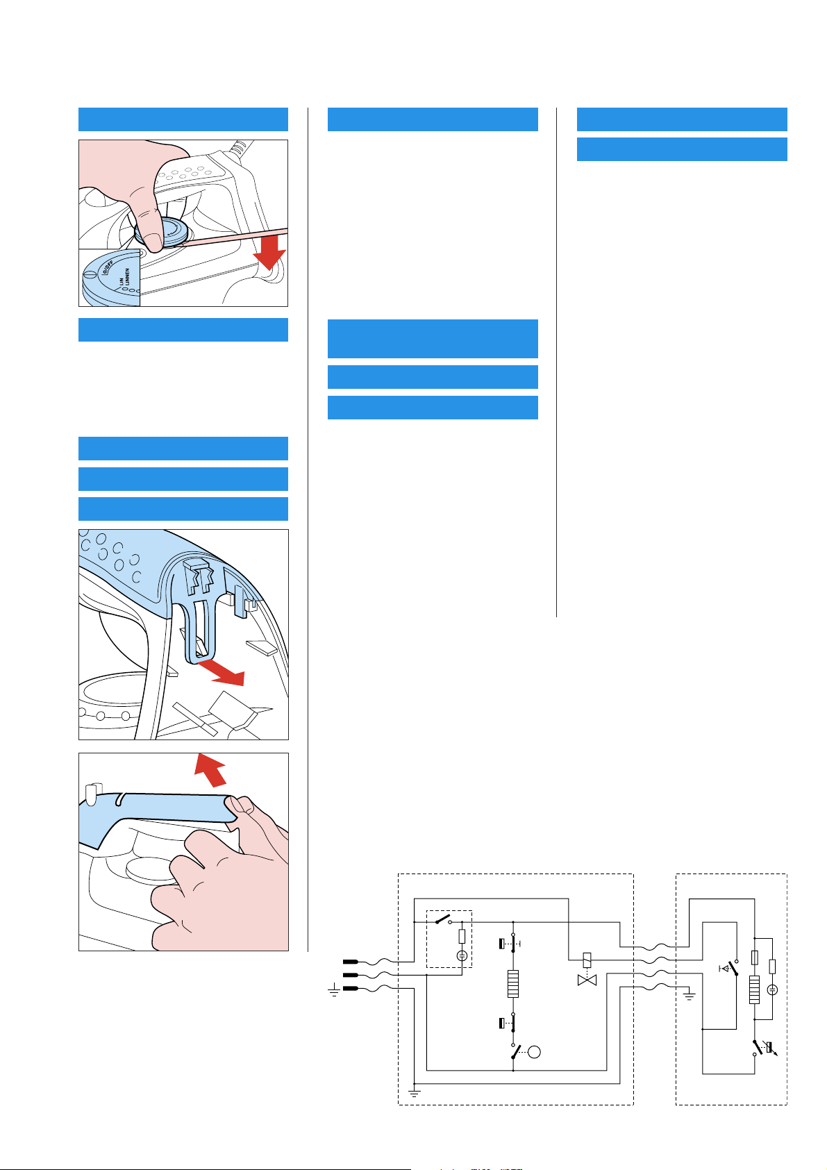
REPAIR INSTRUCTIONS - IRON
- For disassembly, you will need a Torx screwdriver: 362 TR T20 x 100
STAND IRON
Main
switch
F
N
Boiler
thermostat
Boiler
heating
element
Cut
out
Electro-
valve
Steamswitch
p
Thermostat
2-5
Page 3

PARTS LIST & EXPLODED VIEW - IRON
3
GC6063
7
8
A
2
5
B1
12
B2
4
B3
1
9
6
C1
C2
C3
10
11
Pos Service code Description
1
4239 021 19670
2
4239 026 15690
3
4239 026 15970
4
4239 021 19630
5
4239 017 08950
6
4239 021 19660
7
4239 021 19570
8
4239 026 15580
9
4239 015 98410
10
4239 026 15930
11
4239 021 19770
12
4239 026 15650
Dial
Backplate
Inlay
Iron Lamp
Micro switch
Iron Handle
Intermediate cable + micro switch
Swivel
Thermostat bush
Iron skirt
Soleplate unit
Electrovalve trigger
3-5
Page 4

DISASSEMBLY & REASSEMBLY ADVICE - STAND
GC6063
SAFETY CAP 21
COMPLETE TRAY 22
Press tray anchorage rubber 23 through
the tray
BACK REST ASSY 31
HOSE CLAMP 32
SUPERIOR STAND
PRINTED 29)
Remove screws A (4x)
A 4x
REASSEMBLY
COMPLETE TRAY 22
Insert back rest through the complete
tray, hose clamps added to the legs of
the back rest as shown above.
With tray lifted, use a screw driver to
upwardly unplug hose clamps at the
foot of back rest.
Note: Hose clamps MUST BE
unplugged before back rest can
be removed.
When both hose clamps are unplugged,
remove back rest by pulling one leg
fi rst, then the other leg.
Remove the SUPERIOR STAND and
you will see the respective parts of the
Boiler.
REPAIR INSTRUCTIONS - STAND
- For disassembly, you will need a Torx screwdriver 362 TR T20 x 100
- Be careful of the sharp edges of the stainless steel tray assy. a thick glove when
removing the tray assy.
- To avoid damage to the sealings and components of the boiler, NEVER clean the
boiler with vinegar, descaling agent or other chemicals.
- The boiler does not contain serviceable parts. Never disassemble and service any
components on the boiler assy.
- The boiler is required to be rinsed after every 10 times usage.
- ALWAYS replaced boiler assy (Pos 26) when
mechanical safety valve at the cap has been activated
•
thermal fuse/thermostat at boiler bottom is open
•
REMEMBER to plug in the hose
clamps after inserting back rest to the
superior stand.
Note: The hose clamps lock the back
rest into position.
4-5
Page 5

PARTS LIST & EXPLODED VIEW - STAND
GC6063
31
22
32
29
21
33
A
23
A
A
A
38
27
28
Pos Service code Description
21
4239 026 15630
22
4239 021 19590
23
4239 015 55310
24
4239 015 55280
25
4239 000 09150
4239 000 09260
26
4239 021 19990
27
4239 010 08870
Safety cap
Complete tray
Tray rubber foot
Boiler rubber foot
Intermediate supply cable (Europe)
Intermediate supply cable (Italy)
Boiler assy
Electrovalve
Pos Service code Description
28
4239 017 08810
29
4239 021 20060
30
4239 026 15980
31
4239 021 19650
32
4239 026 00230
33
4239 015 55300
38
4239 017 09151
Main switch
Superior stand
Inferior stand
Back rest assy
Hose clamp
Filling hole gasket
Te fl on ring
26
30
24
25
5-5
 Loading...