

Page 1
MP3 Mini Hi-Fi System
FWM593/55/BK
FWM593X/85
CONTENTS
Technical specification ..................................................................1-2
Service measurement setup..........................................................1-3
Service aids .................................................................................1-4
Instructions on CD playability ................................................2-1..2-2
Disassembly diagram............ ................................................3-1..3-2
Block diagram................................................................................4-1
Wiring diagram ..............................................................................4-2
Main board
Circuit diagram ..................................................................5-1..5-2
Layout diagram..................................................................5-3..5-4
AMP board
Circuit diagram .........................................................................6-1
Layout diagram..................................................................6-2..6-3
Front board
Circuit diagram .........................................................................7-1
Layout diagram..................................................................7-2..7-3
MCU board
Circuit diagram .........................................................................8-1
Layout diagram..................................................................8-2..8-3
CD Board
Circuit diagram. ........................................................................9-1
Layout diagram..................................................................
Exploded view diagram ...............................................................10-1
Mechanical parts list....................................................................10-2
Electrical parts list............................................................... 11-1..11-3
Revision list.................................................................................. 12-1
9-2..9-3
©
Copyright 2008 Philips Consumer Electronics B.V. Eindhoven, The Netherlands
All rights reserved. No part of this publication may be reproduced, stored in a retrieval
system or transmitted, in any form or by any means, electronic, mechanical, photocopying,
or otherwise without the prior permission of Philips.
Published by SL 0826 Service Audio Subject to modification
Version 1.1
3141 785 32801
Page 2

TECHNICAL SPECIFICATION
1 - 2
AMPLIFIER
RMS output power
1KHz (Low channel-both channels driven) .......
.......................................................... 100 W per channel
10KHz (High channel-both channels driven) ....
.......................................................... 100 W per channel
Total output power ...........................................580 W
Signal-to-noise ratio .......................... 67 dB A (IEC)
Frequency response .......................... 60 – 16000 Hz
Input sensitivity
AUX ................................................. 1500mV/2000mV
Output
Speakers .................................................................... 3 Ω
(1) (3 Ω, 1 kHz, 10% THD)
CD/MP3-CD PLAYER
Number of programmable tracks ......................... 40
Frequency response ............. 60 – 16000 Hz -3dB
Signal-to-noise ratio ....................................... 75 dB A
Channel separation .......................... 50 dB (1 kHz)
Total harmonic distortion ................................. < 1.5%
MPEG 1 Layer 3 (MP3-CD) .......... MPEG AUDIO
MP3-CD bit rate ....................................... 32-256 kbps
(128 kbps advised)
Sampling frequencies ....................... 32, 44.1, 48 kHz
TUNER
FM wave range ................................... 87.5 – 108 MHz
AM wave range (9 kHz) ............... 531 – 1602 kHz
AM wave range (10 kHz) ............. 530 – 1700 kHz
Tuning grid ............................................................ 9/10 kHz
Number of presets ........................................................ 40
Antenna
FM ....................................................................... 75 Ω wire
AM .............................................................. Loop antenna
USB PLAYER
USB ................................................................... 12Mb/s, V1.1
......................................... support MP3 and WMA files
Number of albums/folders ................. maximum 99
Number of tracks/titles ...................... maximum 999
SPEAKERS
System 2-way; double por t bass reflex
Impedance ........................................................................ 3 Ω
Woofer ................................................................... 2 x 5.25”
Tweeter ...................................................................2 x 1.75”
Dimensions (w x h x d) . 225 x 430 x 275 (mm)
Weight .......................................................... 4.928 kg each
SUBWOOFER
Impedance ........................................................................ 6 Ω
Subwoofer driver ............................................................. 8”
Subwoofer output power ................................. 180 W
Dimensions (w x h x d)274 x 430 x 342.3 (mm)
Weight ...................................................................... 6.747 kg
GENERAL
Material/finish ................................... Polystyrene/Metal
AC Power ........................... 110 – 127 / 220 – 240 V;
....................................................... 50/60 Hz, Switchable
Power Consumption
Active ........................................................................ 130 W
Standby .................................................................. ≤ 20 W
Dimensions (w x h x d) .. 265 x 345 x 382 (mm)
Weight (without speakers) ........................... 8.505 kg
Specifications and external appearance are
subject to change without notice.
Page 3
e
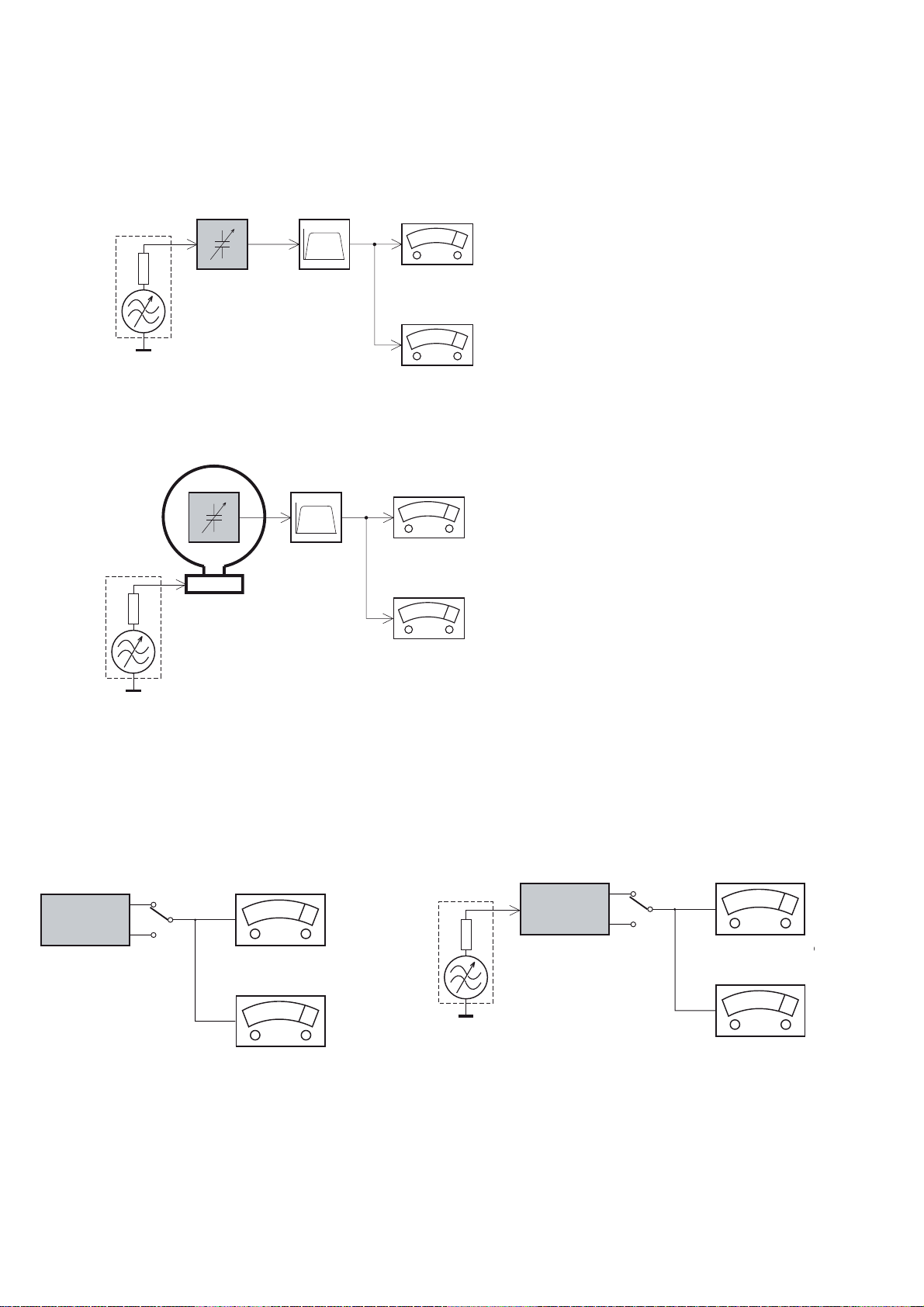
MEASUREMENT SETUP
Tuner FM
1-3
Bandpass
LF Voltmeter
e.g. PM2534
RF Generator
e.g. PM5326
DUT
250Hz-15kHz
e.g. 7122 707 48001
Ri=50:
S/N and distortion meter
e.g. Sound Technology ST1700B
Use a bandpass filter to eliminate hum (50Hz, 100Hz) and disturbance from the pilottone (19kHz, 38kHz).
Tuner AM (MW,LW)
RF Generator
e.g. PM5326
Ri=50:
DUT
Frame aerial
e.g. 7122 707 89001
Bandpass
250Hz-15kHz
e.g. 7122 707 48001
LF Voltmeter
e.g. PM2534
S/N and distortion meter
e.g. Sound Technology ST1700B
To avoid atmospheric interference all AM-measurements have to be carried out in a Faraday´s cage.
Use a bandpass filter (or at least a high pass filter with 250Hz) to eliminate hum (50Hz, 100Hz).
CD
Use Audio Signal Disc
(replaces test disc 3)
DUT
L
R
SBC429 4822 397 30184
S/N and distortion meter
e.g. Sound Technology ST1700B
LEVEL METER
e.g. Sennheiser UPM550
-
Recorder
Use Universal Test Cassette CrO2 SBC419 4822 397 30069
or Universal Test Cassette
LF Generator
e.g. PM5110
Fe SBC420 4822 397 30071
DUT
L
R
S/N and distortion met
e.g. Sound Technology ST170
LEVEL METER
e.g. Sennheiser UPM550
with FF-filter
Page 4
SERVICE AIDS
1-4
GB
All ICs and many other semi-conductors are
susceptible to electrostatic discharges (ESD).
Careless handling during repair can reduce life
drastically.
When repairing, make sure that you are
connected with the same potential as the mass
of the set via a wrist wrap with resistance.
Keep components and tools also at this
potential.
WARNING
GB
Safety regulations require that the set be restored to its original
condition and that parts which are identical with those specified,
be used
Safety components are marked by the symbol
!
.
ESD
CLASS 1
LASER PRODUCT
Lead free
Page 5
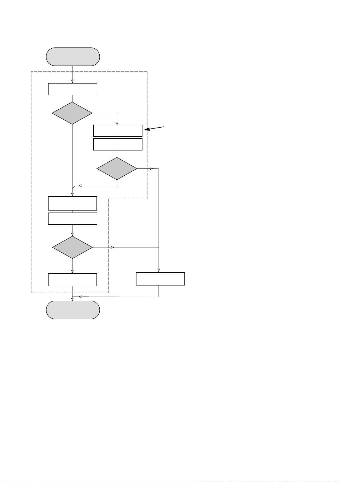
INSTRUCTIONS ON CD PLAYABILITY
Customer complaint
"CD related problem"
Set remains closed!
check playability
1
2 - 1
playability
ok ?
Y
Play a CD
for at least 10 minutes
check playability
playability
ok ?
Y
N
"fast" lens cleaning
check playability
playability
ok ?
N
3
N
Y
For flap loaders (= access to CD drive possible)
cleaning method
4 is recommended
add Info for customer
"SET OK"
2
return set
1 - 4 For description - see following pages
Exchange CDM
Page 6
INSTRUCTIONS ON CD PLAYABILITY
2 - 2
1
PLAYABILITY CHECK
For sets which are compatible with CD-RW discs
use CD-RW Printed Audio Disc ....................7104 099 96611
TR 3 (Fingerprint)
TR 8 (600µ Black dot) maximum at 01:00
• playback of these two tracks without audible disturbance
playing time for: Fingerprint
Black dot from 00:50 to 01:10
• jump forward/backward (search) within a reasonable time
For all other sets
use CD-DA SBC 444A..................................4822 397 30245
TR 14 (600µ Black dot) maximum at 01:15
TR 19 (Fingerprint)
TR 10 (1000µ wedge)
• playback of all these tracks without audible disturbance
playing time for: 1000µ wedge 10seconds
Fingerprint 10seconds
Black dot from 01:05 to 01:25
• jump forward/backward (search) within a reasonable time
10seconds
4
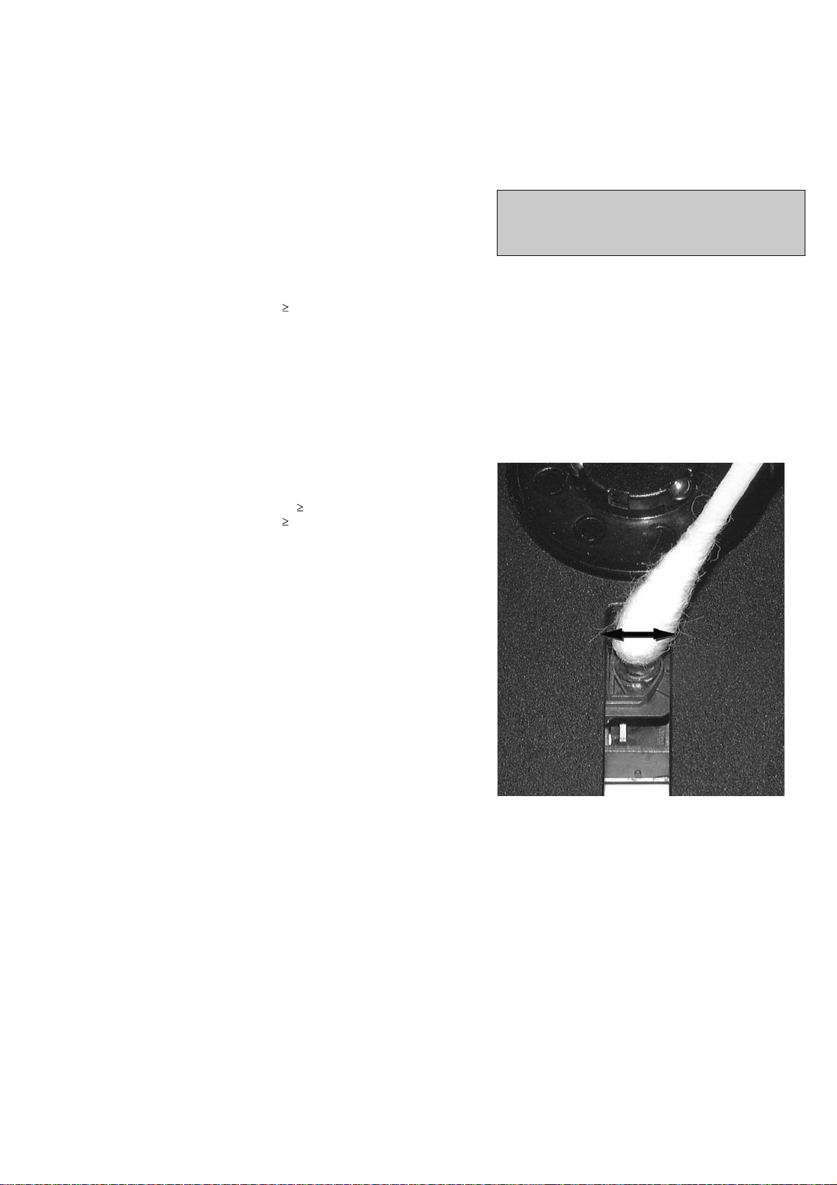
LIQUID LENS CLEANING
Before touching the lens it is advised to clean the
surface of the lens by blowing clean air over it.
This to avoid that little particles make scratches on
the lens.
Because the material of the lens is synthetic and coated
with a special anti-reflectivity layer, cleaning must be done
with a non-aggressive cleaning fluid. It is advised to use
“Cleaning Solvent
The actuator is a very precise mechanical component and
may not be damaged in order to guarantee its full function.
Clean the lens gently (don’t press too hard) with a soft and
clean cotton bud moistened with the special lens cleaner.
The direction of cleaning must be in the way as indicated in
the picture below.
2
CUSTOMER INFORMATION
It is proposed to add an addendum sheet to the set which
informs the customer that the set has been checked
carefully - but no fault was found.
The problem was obviously caused by a scratched, dirty or
copy-protected CD. In case problems remain, the customer
is requested to contact the workshop directly.
The lens cleaning (method 3) should be mentioned in the
addendum sheet.
The final wording in national language as well as the printing
is under responsibility of the Regional Service Organizations.
Page 7
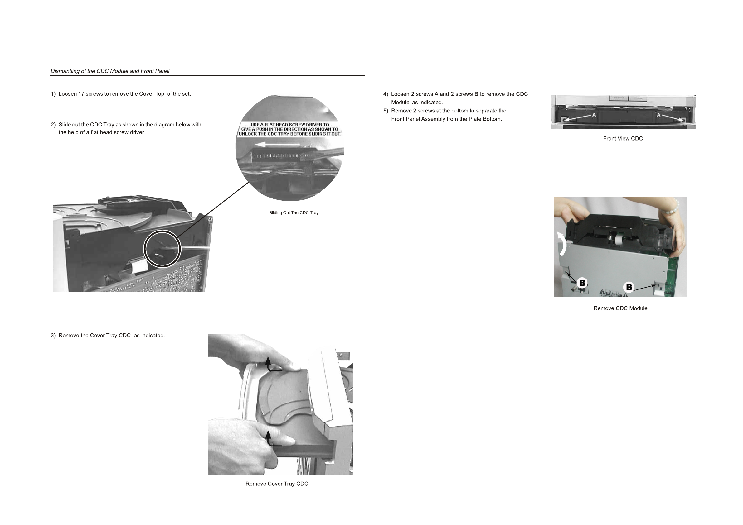
DISASSEMBLY DIAGRAM VIEW
PART 1
3 - 1
3 - 1
Page 8
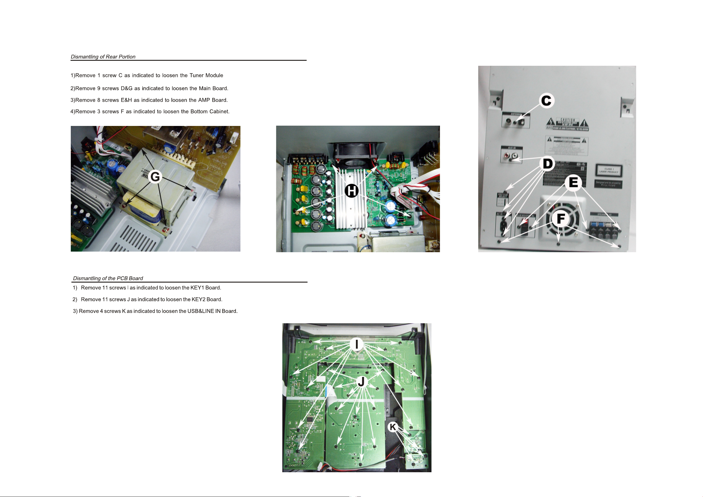
DISASSEMBLY DIAGRAM VIEW
PART 2
3 - 2
3 - 2
Page 9
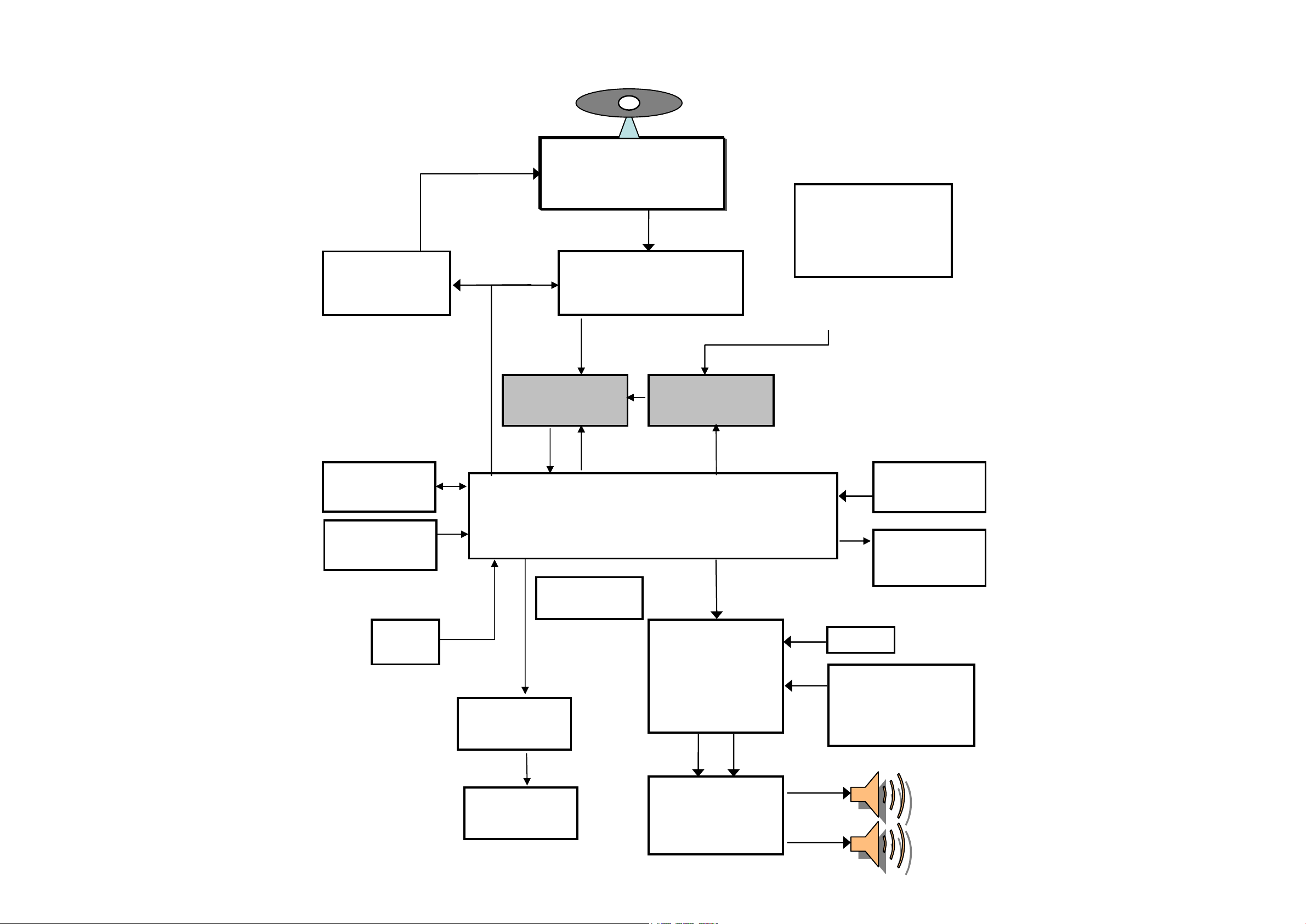
3CDC CD Loader
PICK-UP MECHA
SANYO : DA-11VF
4 CH
MOTOR DRIVER
(BA5826)
ROHM
RF AMP+SSP+DSP
(BU9543)
PLL Tuner
(SANYO
LC72131+TA1823
or Panasonic TM10)
MCS LOGIC BX8800
MP3/WMA En/De + MCU +USB/CARD
SOUND CONTROL
SW+VOL+EQ
(TDA7468 or
/PT2314)
POWER AMP
TDA8920
AUX
DISPLAY
VFD
USB/SD
MMC
NOR FLASH
SST39VF400A
SDRAM
16Mbit
Port Expander
74HC4094
VFD DRIVER
PT6315
Spectrum
analyzers
LED controller
for Light Box
(May use)
MUX
74VC157
ADC
CE2632
Karaoke
( use standard
FWM582 Karaoke
board)
SET BLOCK DIAGRAM
4 - 1 4 - 1
Page 10
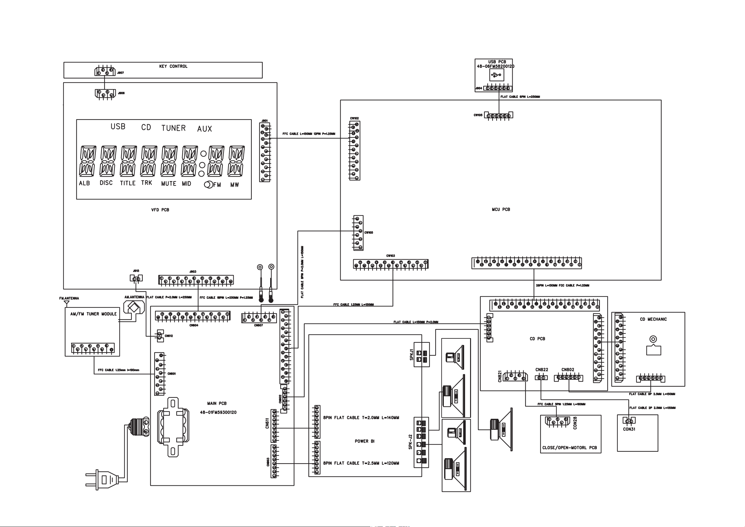
SET WIRING DIAGRAM
4 - 2 4- 2
Page 11

CIRCUIT DIAGRAM - MAIN BOARD
PART 1
5 - 15 - 1
Page 12

CIRCUIT DIAGARM - MAIN BOARD
PART 2
5 - 2 5 - 2
Page 13

LAYOUT DIAGARM - MAIN BOARDMAIN BOARD
COMPONENT SIDE VIEW
Page 14

LAYOUT DIAGARM - MAIN BOARDMAIN BOARD
COPPER SIDE VIEW
Page 15

CIRCUIT DIAGRAM - AMP BOARD
6 - 1
6 - 1
Page 16

LAYOUT DIAGARM - AMP BOARDAMP BOARD
COMPONENT SIDE VIEW
6 - 2
6 - 2
Page 17

LAYOUT DIAGARM - AMP BOARDAMP BOARD
COPPER SIDE VIEW
6 -3 6 - 3
Page 18

CIRCUIT DIAGRAM - FRONT BOARD
7 - 1 7 - 1
Page 19

LAYOUT DIAGARM - FRONT BOARD
COMPONENT SIDE VIEW
7 - 2 7 - 2
Page 20

LAYOUT DIAGARM - FRONT BOARD
COPPER SIDE VIEW
7 - 3
7 - 3
Page 21

CIRCUIT DIAGRAM - MCU BOARD
8 - 1 8 - 1
Page 22

LAYOUT DIAGARM - MCU BOARD
COMPONENT SIDE VIEW
8 - 2 8 - 2
Page 23

LAYOUT DIAGARM - MCU BOARD
COPPER SIDE VIEW
8 - 3
8 - 3
Page 24

CIRCUIT DIAGRAM - CD BOARD
9 - 1
9 - 1
Page 25

LAYOUT DIAGRAM - CD BOARD
COMPONENT SIDE VIEW
9 - 2
9 - 2
Page 26

LAYOUT DIAGRAM - CD BOARD
COPPER SIDE VIEW
9 - 3
9 - 3
Page 27

EXPLODED VIEW DIAGRAM
10 - 1 10 - 1
Page 28

e
.
10 - 2
10 - 2
MECHANICAL PARTSLIST
101 996510016093 FTD HOLDER
102 996510016094 LED HOLDER
103 996510016095 LED BRACKET
104 996510016096 LED LIGHT GUIDE
154 996510016113 VOL KNOB COVER
201 996510016104 FRONT CABINET
205 996510016105 FOOT HOLDER
206 996510016106 3CDC DOOR
207 996510016107 LEFT PANEL AROUND VOL
209 996510016108 RIGHT PANEL AROUND VOL
210 996510016109 TOP COVER
211 996510016110 LEFT COVER
212 996510016111 RIGHT COVER
213 996510016112 BOTTOM COVER
214 996510016114 TOP CD BUTTON
215 996510016115 ALBUM BUTTON
216 996510015507 USB DELETE BUTTON
217 996510016116 TITLE BUTTON
218 996510016117 STOP BUTTON
219 996510016118 PLAY BUTTON
220 996510016119 MODE BUTTON
221 996510016120 PROGRAM BUTTON
222 996510016121 POWER BUTTON
223 996510016122 VOL KNOB
224 996510016123 MAX SOUND BUTTON
MECHANICAL PARTSLIST
J016 996510016103 14P FFC.1.25mm L=180mm
J017 996510015486 18P FFC.1.25mm L=150mm
J018 996500040407 18P FFC 1.25mm L=130mm
T001 996510016098 TRANS EI86xS65 127/240V
T002
J011 996510012091 FERRITE CORE 22.5x15x6.5mm
996510016100 TUNER MODULE MT004MS0-6I
!
ACCESSORIES
FM 996510009429 FM ANT (GREY) 1.5M CE/75
J010 996510016101 AM LOOP ANTENNA
6 996510003974 REMOTE CONTROL
7
S001
S002
J012 996510002103 CONN. CORD 3.5 ST/PLUGx2 500mm
Note: Only these parts mentioned in the list ar
996500037714 AC CORD SET VDE/BRAZIL APP 1.8
!
996510035746
996510016373
normal service parts
SPK BOX (RED)SINGLE (/BK)
SUBWOOFER BOX (/BK)
225 996510016124 CLUSTER BUTTON
226 996510016125 USB RECORD BUTTON
227 996510016126 JAZZ-POP BUTTON
228 996510016127 ROCK-CLASSIS BUTTON
229 996510016128 DDB BUTTON
230 996510016129 DISC AND TUNER BUTTON
231 996510016130 USB AND AUX BUTTON
232 996510015510 MIC KNOB
234 996510016131 IR LENS
235 996510016132 POWER LIGHT GUIDE
236 996510016133 VOL LIGHT GUIDE
238 996510016134 DBB LIGHT GUIDE
239 996510016135 MAX BUTTON LIGHT GUIDE
240 996510016136 BADGE PHILIPS
242 996510016137 MIDDLE STRAP SOUND BUTTON
243 996510016138 DISPLAY TOP BAR
244 996510016139 MIDDLE STRAP L
245 996510016140 MIDDLE STRAP R
246 996510016141 MIDDLE STRAP TOP BUTTON
247 996510016142 VOL RING
248 996510016143 USB RING
4 996510018624 3CD MECHA PART DA11VF(No PCBA)
J013 994000004462 4P FFC 1.25MM L=270MM(AA)
J014 996510016102 9P FFC.1.25mm L=80mm
J015 994000002431 FFC CABLE 10P L=120MM
Page 29

ELECTRICAL PARTSLIST
Y
Y
e
.
MAIN BOARD ASSEMBL
CN606 994000001221 V/RCA JACK 2P
F901
F902
F903
F904
IC601 996510005250 IC TDA7468D
IC602 994000001201 IC NJM4556AM
IC603 994000000253 IC (SAMSUNG) KA7808
IC606 994000004549 IC KA7805E
IC607 994000001247 IC HEF4094BT
IC608 994000001247 IC HEF4094BT
IC609 994000001201 IC NJM4556AM
J001 996510014304 AC SOCKET UL APP
SW901 994000001323 SWITCH
U901 996510016090 IC AP1117E33L-13
AMP BOARD ASSEMBL
JSPK1 996510016371 SPK JACK
JSPK2 996510016097 SPK JACK 8P PT-24V11A
U301 996510003980 IC TDA8920(SOT566-3) 2X100W
U302 996510003980 IC TDA8920(SOT566-3) 2X100W
U304 996500042457 IC HEF4013BT
996510002426 CERAMIC FUSE 3.9x10.5mmW
!
996510002426 CERAMIC FUSE 3.9x10.5mmW
!
996510002426 CERAMIC FUSE 3.9x10.5mmW
!
994000002459 FUSE PTU 2.5A 250V
!
11 - 1
U305 996500042456 IC 74HCT04D SOP14
U306 996510003980 IC TDA8920(SOT566-3) 2X100W
U307 996500039808 IC SM LM324D
U308 994000001201 IC NJM4556AM
Y301 996500042460 CERAMIC RESONATOR 600KHz
Y302 996500042461 CERAMIC RESONATOR 700KHz
Note: Only these parts mentioned in the list ar
normal service parts
Page 30

ELECTRICAL PARTSLIST
FRONT BOARD ASSEMBLY
D909 996510000438 LED LAMP
D910 996510000438 LED LAMP
D911 996510000438 LED LAMP
D912 996510000438 LED LAMP
D914 996510000438 LED LAMP
D915 996510000438 LED LAMP
D919 996510000438 LED LAMP
D920 996500042443 LED LAMP 2x5x7mm(S.BLUE)
D923 996510000438 LED LAMP
D924 996510000438 LED LAMP
FTD901 996510016092 VFD DISPLAY
J905 996510000344 USB SOCKET
J908 994000001244 V/PHONE JACK 3.5MM
J909 994000001244 V/PHONE JACK 3.5MM
J911 994000001244 V/PHONE JACK 3.5MM
P901 994000000325 OPTIC SENSER (OPTO..)
SW901 994000001243 TACT SWITCH
SW902 994000001243 TACT SWITCH
SW903 994000001243 TACT SWITCH
SW904 994000001243 TACT SWITCH
SW905 994000001243 TACT SWITCH
SW906 994000001243 TACT SWITCH
SW907 994000001243 TACT SWITCH
SW908 994000001243 TACT SWITCH
SW909 994000001243 TACT SWITCH
SW910 994000001243 TACT SWITCH
SW911 994000001243 TACT SWITCH
SW912 994000001243 TACT SWITCH
SW913 994000001243 TACT SWITCH
SW914 994000001243 TACT SWITCH
SW915 994000001243 TACT SWITCH
SW916 994000001243 TACT SWITCH
SW917 994000001243 TACT SWITCH
SW918 994000001243 TACT SWITCH
SW919 994000001243 TACT SWITCH
SW920 994000001243 TACT SWITCH
SW921 994000001243 TACT SWITCH
SW922 994000001243 TACT SWITCH
SW923 994000001243 TACT SWITCH
SW924 994000001243 TACT SWITCH
SW925 994000001243 TACT SWITCH
SW926 994000001243 TACT SWITCH
SW927 994000001243 TACT SWITCH
SW928 994000001243 TACT SWITCH
SW929 994000001243 TACT SWITCH
SW930 994000001243 TACT SWITCH
U901 996510016091 IC PT6324
U902 996510003985 IC ECHO PROCESSOR PT2399S
U903 996510003984 IC CYT78L05 (TO-92)
VR901 996510006586 ROTARY VOLUME F-122KGP B50K L
VR902 996510003986 ROTARY VOLUME
VR903 994000001241 ROTARY ENCODER
11- 2
Page 31

Y
Y
e
.
11 - 3
ELECTRICAL PARTSLIST
CD BOARD ASSEMBL
IC501 996510009311 IC BU9543KV (SMD)
IC502 996510009310 IC BA5826FP
IC505 994000001247 IC HEF4094BT
J001 996510015477 26P FFC.1.25mm L=80mm
Q1523 996510000317 SMD TRANSISTORS BC817-25
Q501 996510000315 SMD TRANSISTORS BC807-25
Q502 994000001193 TRANSISTORS KSB772YS
Q522 996510000317 SMD TRANSISTORS BC817-25
Q523 996510000992 TRANSISTORS SPD18P06P
SW501 994000004552 DETECT SWITCH
SW502 994000004552 DETECT SWITCH
SW503 994000004552 DETECT SWITCH
SW504 994000004552 DETECT SWITCH
U532 996510003998 IC TDA7073A/N4 (/55)
U532 996510035364 IC TDA7073A (SOT16) (-/BK)
X501 994000004551 CRYSTAL 16.9344MHZ +-20PPM
MCU BOARD ASSEMBL
82 994000003669 CD MECHANISM (SANYO) DA11VF
102 996510014310 MAGNET 27x16x4mm 546g
8001 994000004487 16P FFC 1MM L=170MM
8002 996510001327 23P FFC 1.25mm L80mm
8003 994000004457 5P FFC L=200MM(AA)
IC101 996510015478 IC BX8800
IC102 996510009337 IC SST39VF800A-70 8M 3.3V TSOP
IC103 996510001318 IC 74LVC157APW
IC104 996510003990 IC SDRAM M12L16161A-7T
IC105 996510003993 IC V809R
IC106 996510015480 IC WM8782SEDS
IC107 996510009335 IC LM1117S-1.8V SOT-223
WG40G2CVL47 CI801CI
IC191 996510015481 IC HT1381
Q101 994000003937 SMD TRANSISTORS PMBT3906
Q102 996510010292 SMD TRANSISTORS MMBT3904
X101 996510008326 CRYSTAL 12 MHzHC-49/US H=3.5mm
X102 996510015482 CRYSTAL 11.2896MHz
X191 994000004615 CRYSTAL 32.768KHZ 12.5PF
Note: Only these parts mentioned in the list ar
normal service parts
Page 32

12-1
REVISION LIST
V
Version 1.1 (3141 785 32801)
P10-2 is revised.Change SPK box for /BK.(4/23/2010)
*
P11-3 is revised.Change U532 for /BK.(4/23/2010)
*
 Loading...