

Philips FWc798, FW C798SI1 Diagram

Service
Service
Service
Service
FW-C798
A02 - 157
Service
Product Service Group CE Audio
Service Information
Already published Service Informations :
ADDITION TO SERVICE MANUAL
*Power Booster:
Repair information and selected spare parts are now available for
the Power Booster. For this reason layout, circuit drawing and parts
list are enclosed (Page 1 to 10).
30 - 05 - 2002
3139 785 30071
1 1
SPECIFICATIONS
POWER BOOSTER
TABLE OF CONTENTS
Mains voltage : 110-127V/220-240V Switchable for /21/21M
: 120V for /37
Mains frequency : 50/60Hz
Power Consumption : 25W at Standby
: 150W at Active for /21/21M
: 135W at Active for /37
O/P Power : 100W
FTC Power : 85W
I/P Sensitivity : 775mV +/-15%
Frequency Response : 20Hz-20kHz +/-3dB
Channel Different : 2dB (250Hz to 6.3kHz)
Distortion : 0.4% (1W 1kHz)
: 0.4% ( 1W 40Hz)
: 0.9% (1W 16kHz)
Channel Separation : >65dB (1kHz)
: >50dB (250Hz)
: >50dB (10kHz)
Power Booster:
Technical Specifications & Version Variations ................... 1
Power Booster Amplifier Box:
Dismantling Instructions & Service positions ..................... 2
Wiring Diagram ................................................................... 4
Component Layout (/21/21M Version) ............................... 5
Component Layout (/37 Version) ....................................... 6
Circuit Diagram ................................................................... 7
Exploded View & Mechanical parts list .............................. 8
Electrical parts list (Main Board) ........................................ 9
Electrical parts list (Control Board) .................................. 10
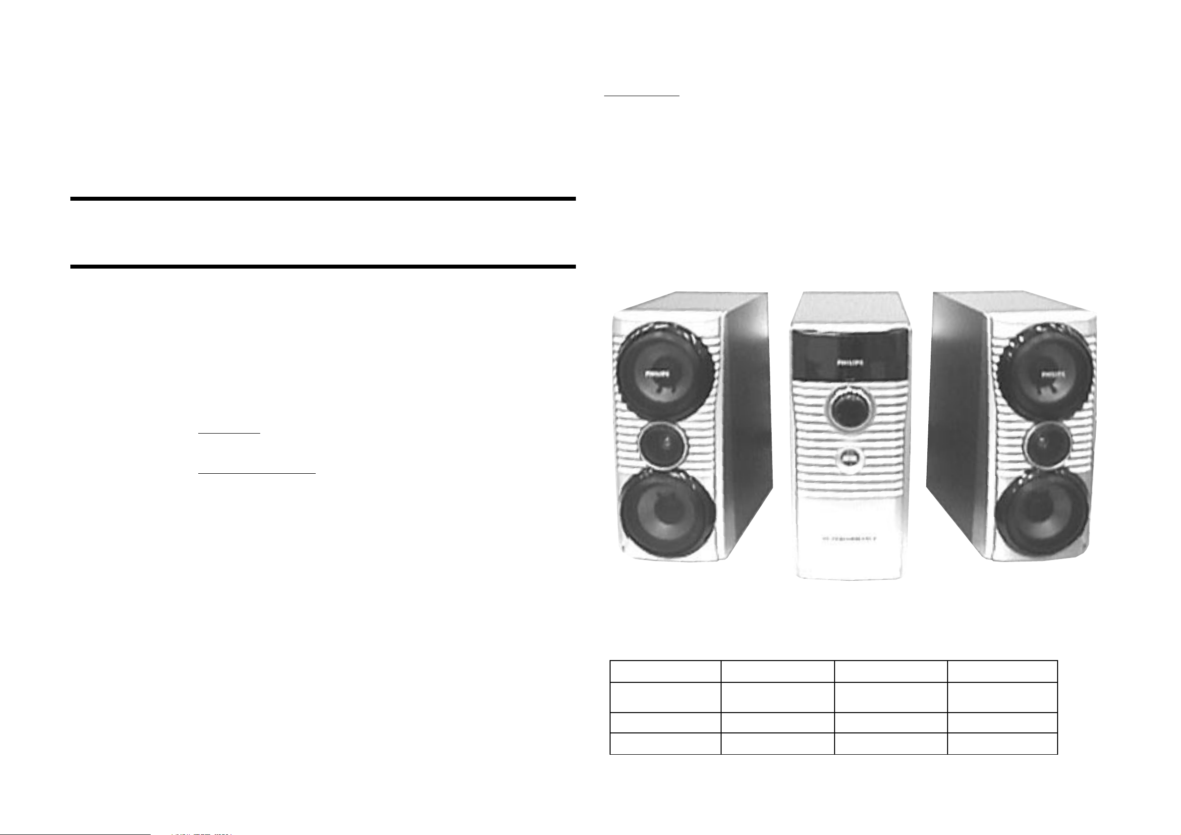
Power Booster Speaker Box
Power Booster Amplifier Box
Power Booster Speaker Box
VERSION VARIATIONS:
FW-C798/21 FW-C798/37 FW-V795/21M
POWER BOOSTER 3139 118 79650 3139 118 79640 3139 118 79630
(PWB-C798/01) (PWB-C798/17) (PWB-V795/01)
AMPLIFIER BOX 9965 000 13808 9965 000 13800 9965 000 13725
SPEAKER BOX 9965 000 13809 9965 000 13801 9965 000 13726

2
DISMANTLING INSTRUCTIONS (POWER BOOSTER AMPLIFIER BOX)
2
Dismantling the Front Assembly
1. Place the Power Booster Amplifier Box as shown in
Picture 1 and Picture 2 and use a screw driver (minus
type) to force open the Front assembly.
Caution: Do not break the bundle of wires to the front.
Picture 1
Service Position A
Picture 2
Dismantling the Control Board and the Panel Ornamental
1. Remove 5 screws A (see Picture 3) to loosen the Control
Board (pos 6).
2. Remove 4 screws B (see Picture 3) to remove the Panel
Ornamental (pos 17).
Picture 3

3
DISMANTLING INSTRUCTIONS (POWER BOOSTER AMPLIFIER BOX)
3
Dismantling the Rear Assembly
1. Remove 4 screws C at the bottom of the Power Booster
Amplifier Box as shown in Picture 4.
2. Remove 15 screws D (see Picture 5) to remove the Metal
Panel (pos 1).
3. Slide out the Main PCB assembly as shown in Service
Position B.
Service Position B
Note: After repair, be very sure that the cables are tied and
restored properly to its original position.
Service Position C
Picture 5Picture 4
 Loading...