

Page 1

FTV2.3
POWER SUPPLY
Chapter 09 page 1
REPAIR METHOD
Page 2

Check VS and VA Output Load
SERVICE TIP:
If the Vs input of the PDP is short circuited a simple test can be done:
Disconnect the set from the mains.
Disconnect ALL cables between PSU and PDP.
Connect a regulated DC power supply (current limited to 1 A) directly to the Vs input of the YSUS board of the PDP
(pin 9 of connector CN 33) and the chassis of the FTV.
Ramp-up the voltage slowly to maximal 5 V. If the current increases to 1 A, the PDP is defect.
The same can be done for the Vs input on the XSUS board: pin 10 of connector CN 23.
The Va inputs on the various boards can also be checked with the same procedure:
The tests must be done on the connectors
CN23: pin 1 (XSUS-board)
Chapter 09 page 2
CN42: pin 1 (ABUSR-board)
CN52: pin 1 (ABUSL-board).
The next pages explains how to repair the power supply outside the
set, with fictive loads
Page 3

Repair The Power Supply Out the Set
Chapter 09 page 3
Short circuit On/Off switch, pin 1 and 2 connector 319.
Connect VCEGO (p13) and VSAGO (p15) of CN307 to a +2,5V from the +3,3v STBY SW.
For a regulated output voltage, connect test point VRS (pin 7) and VRA (pin 9) of CN307 to + 1V. Connect
to the two solder island near connector 307 (flex foil connector).
Load +3,3V stby with 15 Ohm resistor (I must be 0,2A).
Load Vs with Lamp on CN323 pin 10. (lamp220V/75W I =176mA (82,3V))
Vs Min load between 0,1 to 0,5A, Max load = 0,5A
Load VA with lamp on CN 323 pin 1. (lamp 220V/100W I = 200mA (53,6V))
VA Min load between 0,1A to 0,5A Max load = 2A
Load Vcc (5V) with resistor 8,2 Ohm, the Max load for VCC = 7A.
Load 3V3 with resistor 3,3 Ohms or 1,5 Ohm
Connect power supply to mains, by connector 308.
Page 4

Output Connectors
CN319 P3 CN307 P3CN333 and CN323 P7
Pin 9
Power OK
Chapter 09 page 4
P3
VCEGO 2,5VVSAGO 2,5V VRA & VRS 1V
P7
Page 5

Flow Chart Overview Check Points
Check +V standby power supply, + 3,3V and +5V stby on CN319.
Check +V standby power supply, + 3,3V and +5V stby on CN319.
Check Preconditioner +395V on fuse1004.
Check Preconditioner +395V on fuse1004.
Check +Vs switched output voltage on pin 8,9,10 CN323 or pin 7,8,9 CN333 around 80……85V
Check +Vs switched output voltage on pin 8,9,10 CN323 or pin 7,8,9 CN333 around 80……85V
Check + Va output voltage on pin 1 CN323 = around 50….55V
Check + Va output voltage on pin 1 CN323 = around 50….55V
Chapter 09 page 5
Check + Vcc output voltage on pin 1 CN333 = 5,2V
Check + Vcc output voltage on pin 1 CN333 = 5,2V
Check + 3V3 output voltage on pin 8,9,10,11,12 of CN305 = 3,3V
Check + 3V3 output voltage on pin 8,9,10,11,12 of CN305 = 3,3V
Check Power OK line on pin 9 CN319, must be high (4,5V).
Check Power OK line on pin 9 CN319, must be high (4,5V).
Page 6

Switched Standby Voltages
5
n
i
P
Chapter 09 page 6
0
0
5
7
c
I
n
i
a
r
D
+5V Stby out +3,3V Stby out
Minimum load for the +3,3V switched Stby supply
is about 0,2A or 16 ohm
P2
Page 7

Standby Supply Is Not Correct ?
Conditions for normal operating mode of the Stby supply;
Load is about 200mA on the 3,3V output
<100V
Fus.1400,
D6512, D6513, R3506
Chapter 09 page 7
Check V on
drain IC7500?
>100V
Check also
the +25V Hot from Stby PS
Reference is primary ground
Pin 1 IC7500 = 5,8V ?
Check secondary part
Short circuit and
Control loop
P2
Page 8
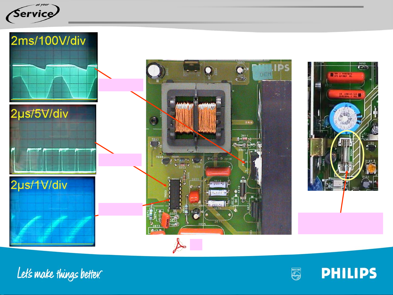
Check Preconditioner
Drain T7610
Pin 11 Gate
Chapter 09 page 8
Pin 13 oscil.
Preconditioner output
Fuse 9004 = 395V
P5
Page 9

Check Preconditioner
Chapter 09 page 9
In normal working conditions output
of preconditioner = 395V on fuse
1004
Tip, it is also possible to check the
preconditioner without load by
removing fuse 1004
Output of D6600 =255V
V start-up pin 16 IC7650 = 395V
Check on IC7650
•Pin 12 Vcc = 14,5V
•Pin 1 Vref = 5V
•Pin 13 Oscilator
Check +25V Hot
preconditioner output = 24,5V
Pin 11 Gate
Voltage feedback pin 3 VFB =5V
Current sense pin 6 CS
P5
Page 10

Start up Conditions LLC Supply
Chapter 09 page 10
Standby supply is switched on and is in continous mode, 3,3V and 5V standby are OK
Diagram P3
P3
VCEGO and VSAGO are connected to 2,5V
T7352 conducts, T7348 is blocked
T7391 is blocked, T73993 is blocked
Diagram P2
Supply_on line = H and T7460, T7465 and T7470 conducts
Relay 1450 & 1460 is closed
Diagram P5
395V Preconditioner is OK
Diagram P2
Check Load on standby supply
Check latch, Thy6348 must be blocked,
If not check protection part P3
P2
P5
Diagram P6
P6
25V_Hot Standby Supply is OK
SW25V_Hot from preconditioner is OK
Ic7093 provide current to pin 15 control IC7001 LLC supply
Check +16V provided by Ic7093
Oscillator and OA/OB Ic7001
Page 11

Check Vs Supply (LLC)
Chapter 09 page 11
LLC control IC Bias supply IC7093
2
4
Primary ground
+Vs switched
on pin 10 CN323
Pin 3 and 6 T5002
or C2011/C2017
Vs=70+10Vrs
= around 80 …85V
P6
Page 12

Check LLC Supply Control Part IC7001
Start up conditions +25v HOT from stby supply
and SW25V Hot from preconditionner are OK?
Check DC voltages IC7001 Pin
•15 Vcc = 16,5V
•5 Vref = 5,1V
Chapter 09 page 12
•10 Fault input = 0V
Check by oscilloscope IC7001 Pin
1 Oscil, drive output 14 OA, 12 OB
P6
If LLC control part does´n start up
check with external DC power supply,
see next page
Page 13

Check LLC Control Part, With External DC Power Supply
Chapter 09 page 13
Connect a external DC power supply
The + to the output of IC7093 (metal part), - to primary ground on cooling plate LLC
Oscilloscope is connected to oscillator pin 1
Adjust the current output of the external DC power supply to 100mA max
Adjust the output voltage to 16V
Control Ic is starting up at 16V, current = 70mA
Check oscillator, One shot timer
OA and OB
Grid Ts7005, Ts7006
See voltages and oscillogrammes next page
P6
Page 14

LLC Supply Control Part
Chapter 09 page 14
One shot
oscil
2,7V
Ref 5,1V
1,8V
4,9V
4,3V
IC7001
MC34067P
17V
OA
OB
4,9V
0,6V
P6
4,9V
Page 15

VS Switch & Sequence Discharge Circuit
Chapter 09 page 15
Start Up Sequence
LLC has started
Pulses are aligned and rectified by D6054 & D6055
Power OK line is H T7058 conducts
VSA_Control is Low
Switch Off Sequence
LLC is switched off
Or +5V standby is switched off
Or Power OK line drops
VS drops & Power OK Line will drop
VSA_Control Line will be High
T7058 will block
P7
T7059 & T7052 are blocked
T7050 conducts
Vs is switched
T7059 conducts
T7050 blocks
T7052 conducts andVS is directly discharged,
while VA is discharged if VS is lower than VA
Page 16

Sart Up Conditions VA Supply
LLC supply has started up and Vs unsw. 77V…95V from LLC is OK
Diagram P3
VSAGO is connconnected to +2,5V
Chapter 09 page 16
P3
Digram P7
P7
T7376 and T7375 conducts
VSA_control line is Low, T7134 is blocked
Start up current is provided by
T7110, T711 and from Drain
Ic7112 to pin 1 VCC
Start up VA
Vs_unsw = OK, T7375
coducts
Check also T7058
Power OK line will be H
but with some delay
Page 17

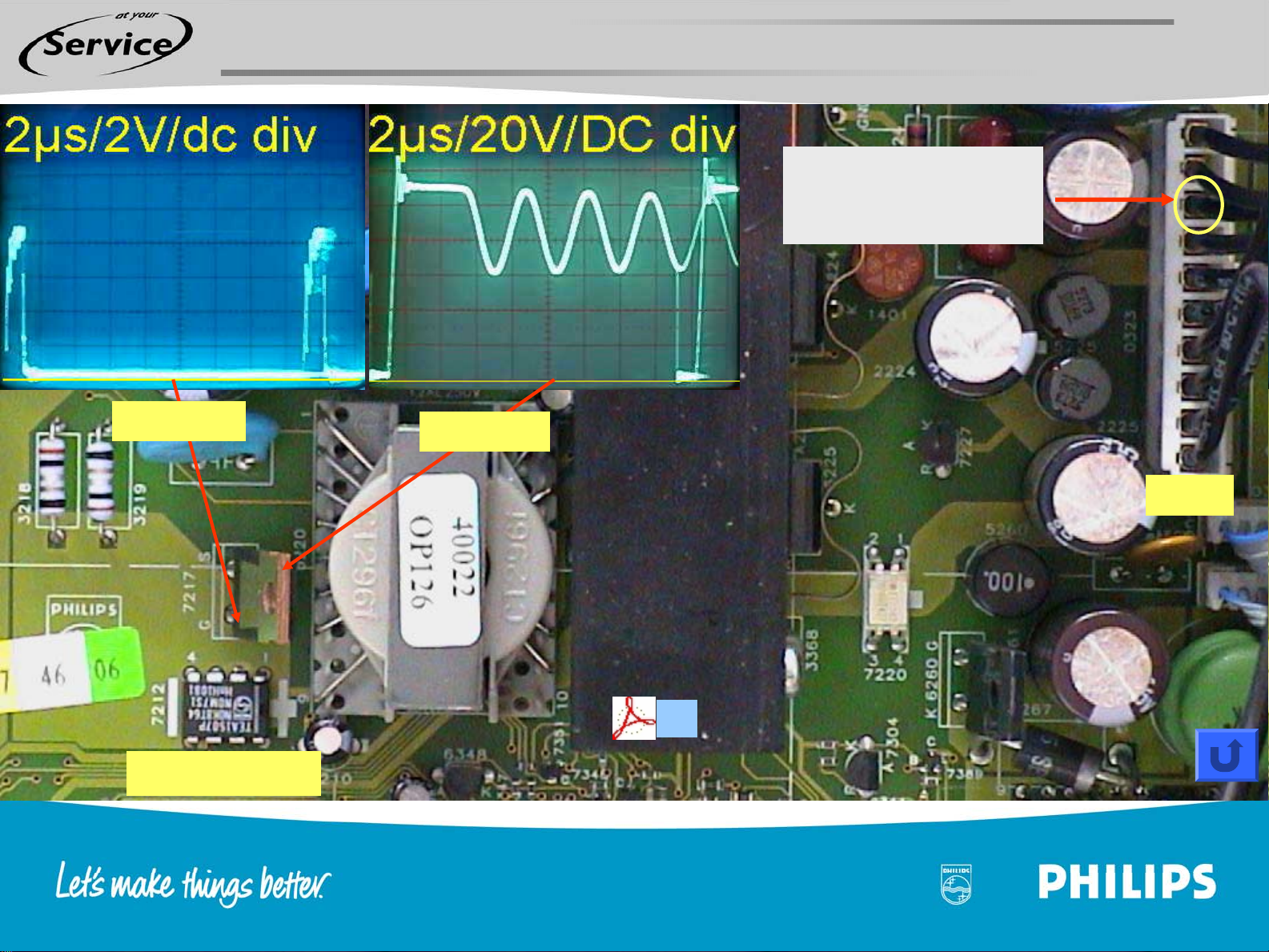
Check VA Supply
VA Control Ic7112
Chapter 09 page 17
Drain T7117
VA DC output pin 1 CN323
1
+VA on pin 1 CN323
= around 50…..55V.
CN323
Va=30+20Vra
P7
Page 18

LLC is OK
VCC Supply Start up Conditions
Diagram P3
Chapter 09 page 18
CN307 pin 13 VCEGO=2,5V
Ts7352 conducts, Ts7351 is blocked
VCC_Go and +18V LLC are on H level
P3
Diagram P7
P7
T7200 conducts and provide start up curent
Start up current is provided by Drain Ic7212
Page 19
VCC Output Voltage
Chapter 09 page 19
Check +VCC = 5,2V
3
or pin 3 CN323
Grid T7217
Control IC7712
Drain 7217
CN323
P7
Page 20

Diagram P6
3V3 Start up Conditions
+18V from LLC supply is OK
Chapter 09 page 20
Diagram P7
IC7260 VCC pin 7 & 8 = 17V
3V3 OVP is Low, Thy6260 is blocked
Check 3,3V OVP
T7389 & IC7330C
Check Oscillator pin 1
P7
Page 21

3,3V Supply
Oscillator Pin1 Output Pin2/3 3V3 outputPin 9 BootPin 17 SS
Chapter 09 page 21
P7
Page 22
3V3 Power Supply Repair With External DC Power Supply
Check if there is no short circuit on the output.
Connect an external DC power supply on C2261 and adjust the
output to 19V, limit the current to 700mA max.
Check the output voltage 3,3V ?
Oscillator pin 1
Chapter 09 page 22
Vcc = 19V
Pin 16 = 5,1V.
Pin 17 SS = 18V
Pin 11 = 0,7V
Pin 12 = 3,2V (if power supply is OK)
P7
Page 23
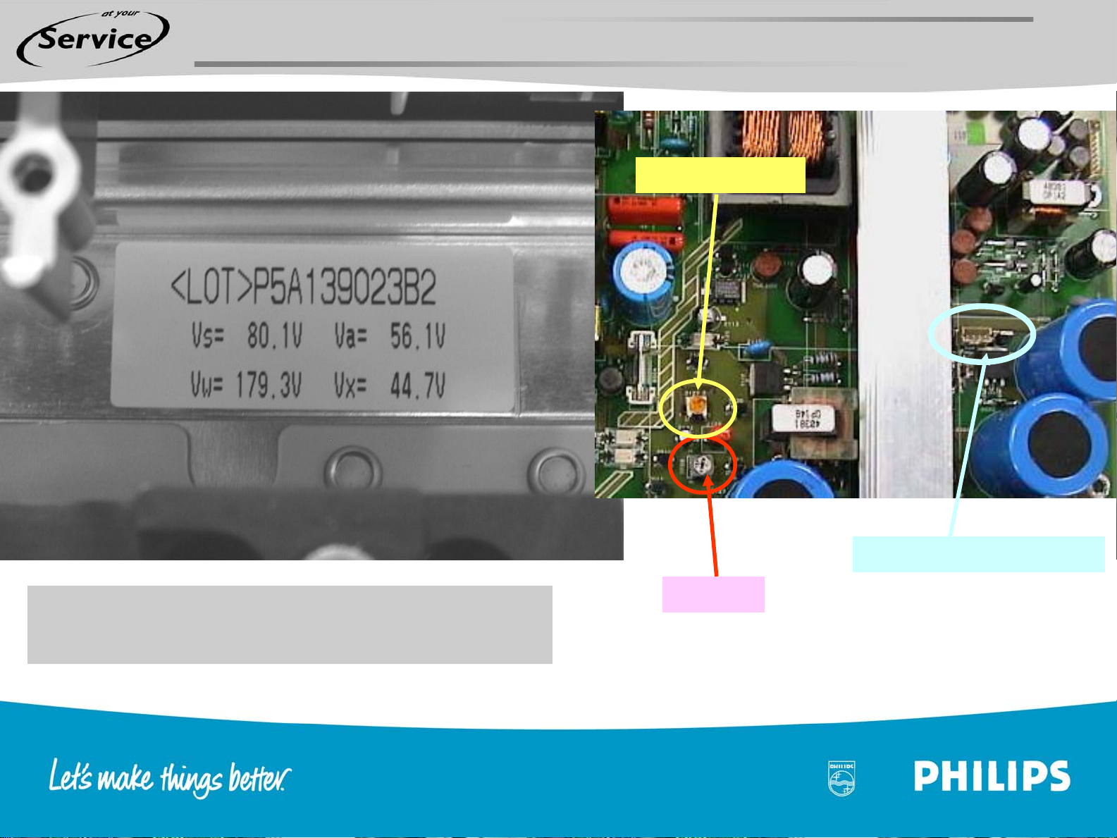
Alignment Vs and Va After Power Supply Repair
VA adjust R3127
Chapter 09 page 23
After repair the +Vs and +VA must be
adjusted
VS and VA test connector
VS adjust
Page 24

Additional Info For Power Supply Alignment
Chapter 09 page 24
Please keep in mind that in case of the following combinations between PSU's and PDP's no or almost no
alignments are needed of the Vs and Va:
PDP with only the Vs feedback loop (-52 in type number of PDP) in combination with the .3 PSU: Keep the SW
feedback loop OFF and align both the Vs and Va as described in the Service manual.
PDP with only the Vs feedback loop (-52 in type number of PDP) in combination with the .3 PSU with precision
resistors: The SW feedback loop can be switched on and then the Va has to checked and aligned with an
accuracy of +/- 1,5V and the potentio meter of the Vs should be positioned in the middle. No further alignments
needed.
PDP with only the Vs feedback loop (-52 in type number of PDP) in combination with the .4 PSU: Switch on the
SW feedback loop and no further alignments are needed.
PDP with the Vs & Va feedback loop (a "B" in the type number of PDP) in combination with the .3 PSU: Keep the
SW feedback loop OFF and align both the Vs and Va as described in the Service manual.
PDP with the Vs & Va feedback loop (a "B" in the type number of PDP) in combination with the .3 PSU with
precision resistors: Switch on the SW feedback loop and no further alignments are needed.
PDP with the Vs & Va feedback loop (a "B" in the type number of PDP) in combination with the .4 PSU: Switch on
the SW feedback loop and no further alignments are needed.
The SW feedback loop can be found in the SAM menu.
Page 25

Chapter 09 page 25
End of the repair method presentation
For your reactions, questions or comments contact
valere.deseranno@philips.com
 Loading...