

Philips LC4.7, FM242(FTV2.1), FTP1.1, FTP2.2 Schematic
Colour Television Chassis
LC 4.7, FM 242 (FTV2.1), FTP 1.1, FTP 2.2 X
Supplement SDI PDP Repair Manual
Contents Page
1 Technical Specifications 2
2 Safety Instructions, Warnings and Notes 6
3 Directions for Use 8
4 Mechanical Instructions 9
5 Diagnostic Software 16
6 Block Diagrams
7 Circuit Diagrams and PWB Layouts
8 Alignments 34
9 Circuit Descriptions 44
10 Spare Parts List 45
©
Copyright 2004 Philips Consumer Electronics B.V. Eindhoven, The Netherlands.
All rights reserved. No part of this publication may be reproduced, stored in a
retrieval system or transmitted, in any form or by any means, electronic,
mechanical, photocopying, or otherwise without the prior permission of Philips.
27
33
Published by MW Service PaCE Printed in the Netherlands Subject to modification EN 3122 785 14990
EN 2 S/SD/HD 3.1 PDP1.
Technical Specifications
1. Technical Specifications
1.1 Model / Chassis overview
PDP Type Model Name H x V Pixel Chassis
37”SDv4 S37SD-YD02 (*)
S37SD-YB01
42”SDv2 S42SD-YD06 (*)
S42SD-YB04
42”SDv3 S42SD-YD05 (*)
S42SD-YB03
42”HDv3 S42AX-XD03 (*)
S42AX-XB01
50HDv3 S50HW-XD03 (*)
S50HW-XB02
(*) are Model names with PSU, but only PDP model without PSU will be delivered as spare part
852 x 480 LC4.7
852 x 480 FM242
852 x 480 LC4.7
1024 x 768 FTP2.2U
1366 x 768 FTP2.2E
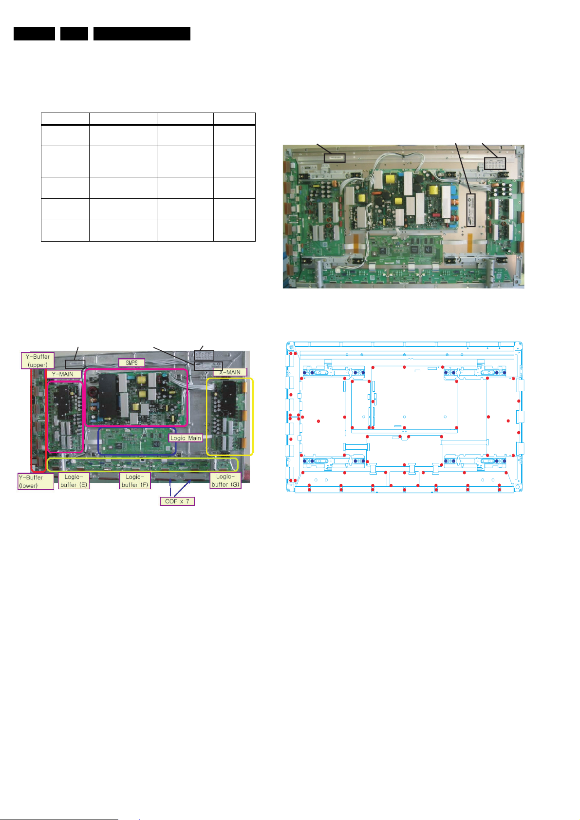
42" SDv2
External View
M3 = X Board + Y Board + Logic Board + PSU + SUB PSU
Serial number Model label Voltage label
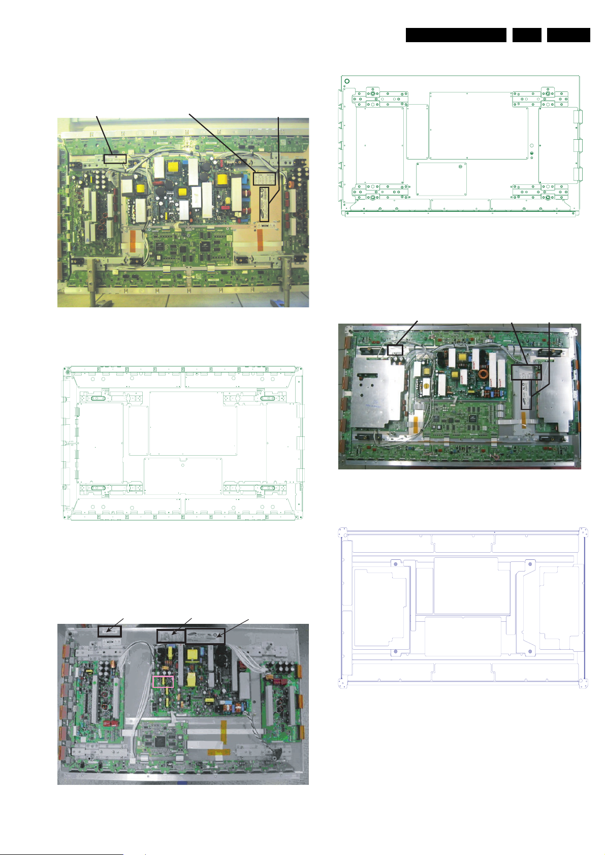
42" SDv3
External View
M3 = X Board + Y Board + Logic Board + PSU + SUB PSU
Serial number label Model label Voltage label
(FTV2.1)
FTP1.1
FTP2.2x
Figure 1-2
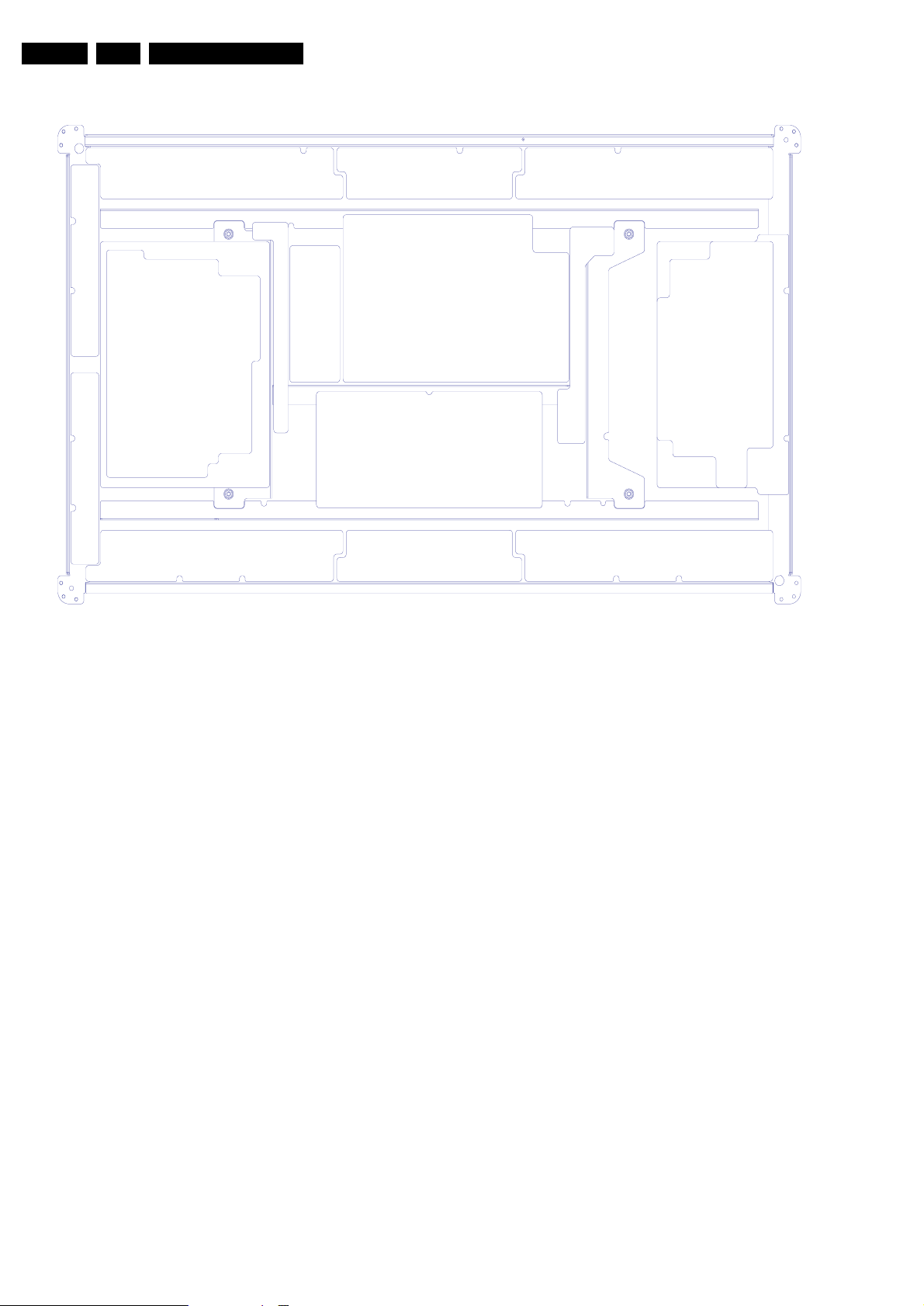
Points of Screw Mount
Figure 1-1
Figure 1-3
Technical Specifications
EN 3S/SD/HD 3.1 PDP 1.
42"HDv3
External View
M3 = X Board + Y Board + Logic Board + PSU + SUB PSU
Serial number label Panel model labelVoltage label
Figure 1-4
Points of Screw Mount
Points of Screw Mount
Figure 1-7
50" HDv3
External View
M3 = X Board + Y Board + Logic Board + PSU + SUB PSU
Serial Number
Voltage
label
Panel module label
Figure 1-5
37" SDv4
External View
M3 = X Board + Y Board + Logic Board + PSU + SUB PSU ‘
Voltage label Serial number label Panel module label
Figure 1-8
Points of Screw Mount
Figure 1-9
Figure 1-6

EN 4 S/SD/HD 3.1 PDP1.
Technical Specifications
1.2 Serial Number
2 6 1 4 0 8 07 0 8 6 5
Serial No : 0001~9999
Date : 01~31
Month : 01~12
Year : 00(2000)
Line No : 1 ~ 9
(0:Pilot Line)
Type : 02~48
~99(2099)
(ex.50HDv3:26)
(Step of even)
Figure 1-10
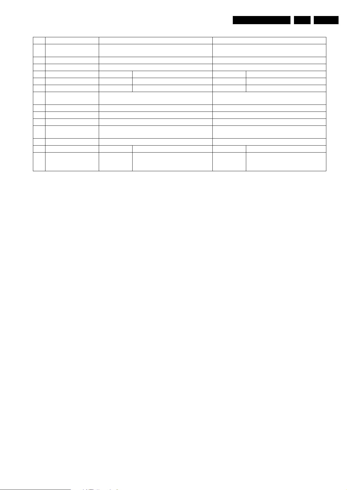
1.3 Specifications
No Item Specification 37” SDV4 Specification 42” SDV2 (ypo6)
1 Pixel 852 (H) x 480 (V) pixels (1 pixel = 1 R,G,B cells) 852 (H) x 480 (V) pixels (1 pixel = 1 R,G,B cells)
2 Number of Cells 2556 (H) x 480 (V) 2556 (H) x 480 (V)
3 Pixel Pitch 0.960 (H) mm x 0.960 (V) mm 1.095 (H) mm x 1.110 (V) mm
4 Cell Pitch R 0.320 (H) mm x 0.960 (V) mm R 0.324 (H) mm x 1.110 (V) mm
G 0.320 (H) mm x 0.960 (V) mm G 0.365 (H) mm x 1.110 (V) mm
B 0.320 (H) mm x 0.960 (V) mm B 0.406 (H) mm x 1.110 (V) mm
5 Display size
Horizontal 817.92mm x Vertical 460.80mm[ 32.30 inch
x 18.14 inch ]
6 Screen size Diagonal 37" Color Plasma Display Module Diagonal 42" Color Plasma Display Module
7 Screen aspect 16 : 9 16 : 9
8 Display color 16.77 million colors 16.77 million colors
9 Viewing angle
Over 160×(Angle with 50% and greater brightness per-
pendicular to PDP module)
10 Dimensions 982 (W) x 582 (H) x 52.9 (D) mm 982 (W) x 582 (H) x 52.9 (D) mm
11 Weight Module 1 About 15.5 kg Module 1 About 16.6 kg
Broadcasting reception-
Vertical frequencyand-
12
PL42SD003C 60Hz/ 50Hz, LVDS PL42SD003C 60Hz/ 50Hz, LVDS
Video/Logic Interface
932.940 (H) mm x 532.800(V) mm[ 36.73 inch x 20.98 inch ]
Over 160×(Angle with 50% and greater brightness per-
pendicular to PDP module)
No Item Specification 42” SDV3
1 Pixel 852 (H) x 480 (V) pixels (1 pixel = 1 R,G,B cells)
2 Number of Cells 2556 (H) x 480 (V)
3 Pixel Pitch 1.095 (H) mm x 1.110 (V) mm
4 Cell Pitch R 0.365 (H) mm x 1.110 (V) mm
G 0.365 (H) mm x 1.110 (V) mm
B 0.365 (H) mm x 1.110 (V) mm
5 Display size
932.940 (H) mm x 532.800(V) mm[ 36.73 inch x 20.98 inch ]
6 Screen size Diagonal 42" Color Plasma Display Module
7 Screen aspect 16 : 9
8 Display color 16.77 million colors
9 Viewing angle
Over 160×(Angle with 50% and greater brightness per-
pendicular to PDP module)
10 Dimensions 982 (W) x 582 (H) x 52.9 (D) mm
11 Weight Module 1 About 16.6 kg
Broadcasting reception-
Vertical frequencyand-
12
PL42SD003C 60Hz/ 50Hz, LVDS
Video/Logic Interface
Technical Specifications
No Item Specification 42” HDV3 Specification 50” HDV3
1 Pixel
2 Number of Cells 3072 (H) x 768 (V) Horizontal 4,098 x Vertical 768 cells
3 Pixel Pitch Horizontal 912mm x Vertical 693mm Horizontal 810mm x mmVertical 810mm
4 Cell Pitch R Horizontal 0.304mm x Vertical 693mm R Horizontal 270mm x Vertical 810mm
5 Display size
6 Screen size Diagonal 42" Color Plasma Display Module Diagonal 50" Color Plasma Display Module
7 Screen aspect 16 : 9 16 : 9
8 Display color 16.77 million colors 16.77 million colors
9 Viewing angle
10 Dimensions 982 (W) x 582 (H) x 52.9 (D) mm 1184(W) x 700 (H) x 60.1 (D) mm
11 Weight Module 1 About 18.0 kg Module 1 About 18.0 kg
Broadcasting reception-
12
Vertical frequencyand-
Video/Logic Interface
Horizontal 1.024 xVertical 768 pixels(1 pixel = 1 R,G,B
cells)
G Horizontal 0.304mm x Vertical 693mm G Horizontal 270mm x Vertical 810mm
B Horizontal 0.304mm x Vertical 693mm B Horizontal 270mm x Vertical 810mm
932.940 (H) mm x 532.800(V) mm[ 36.73 inch x 20.98 inch ]
Over 160×(Angle with 50% and greater brightness per-
pendicular to PDP module)
PL42SD003C 60Hz/ 50Hz, LVDS PL42SD003C 60Hz/ 50Hz, LVDS
Horizontal 1366 x Vertical 768 pixels(1 pixel = 1 R,G,B
cells)
Horizontal 1106.46mm x Vertical 622.08mm
Over 160×(Angle with 50% and greater brightness per-
pendicular to PDP module)
EN 5S/SD/HD 3.1 PDP 1.

EN 6 S/SD/HD 3.1 PDP2.
Safety Instructions, Warnings and Notes
2. Safety Instructions, Warnings and Notes
** To prevent the risks of unit damage, electrical shock and radiation, take the following safety, service, and ESD precautions.
2.1 Safety instructions
It is not allowed to operate the FTV-set without glass plate. One
function of this glass plate is to absorb Infrared Radiation.
Without this glass plate the level of Infrared Radiation produced
by the plasma display could damage your eyes.
1. Safety regulations require that during a repair: – the set should be connected to the mains via an
isolating transformer ( in this particular case a
transformer of
– safety components, indicated by the symbol
should be replaced by components identical to the
original ones;
2. Safety regulations require that after a repair the set must
be returned in its original condition. In particular attention
should be paid to the following points.
– Note: The wire trees should be routed correctly and
fixed with the mounted cable clamps.
– The insulation of the mains lead should be checked for
external damage.
– The electrical DC resistance between the mains plug
and the secondary side should be checked (only for
sets that have mains isolated power supply). This
check can be done as follows:
– unplug the mains cord and connect a wire between the
two pins of the mains plug;
– set the mains switch to the on position (keep the mains
cord unplugged!);
– measure the resistance value between the pins of the
mains plug and the metal shielding of the tuner or the
aerial connection on the set. The reading should be
between 4.5 M
– switch off the TV and remove the wire between the two
pins of the mains plug.
– The cabinet should be checked for defects to avoid
touching of any inner parts by the customer.
≥ 800 VA);
Ω and 12 MΩ;
2.2 Warnings
1. ESD
All ICs and many other semiconductors are susceptible to
electrostatic discharges (ESD
during repair can reduce life drastically. When repairing,
make sure that you are connected with the same potential
as the mass of the set by a wristband with resistance.
Keep components and tools also at this same potential.
2. Available ESD protection equipment: – complete kit ESD3 (combining all 6 prior products -
small table mat) 4822 310 10671
– wristband tester 4822 344 13999
3. Never replace modules or other components while the unit is switched on.
4. When making settings, use plastic rather than metal tools.
This will prevent any short circuits and the danger of a
circuit becoming unstable.
). Careless handling
• PDP module has a lot of electric devices. Service engineer
must wear equipment(for example, earth ring) to prevent
electric shock and working clothes to prevent electrostatic.
• PDP module use a fine pitch connector which is only
working by exactly connecting with flat cable. Operator
must pay attention to a complete connection when
connector is reconnected after repairing.
• The capacitor’s remaining voltage in the PDP module’s
circuit board temporarily remains after power is off.
Operator must wait for discharging of remaining voltage
during at least 1 minute.
2.4 Safety Precautions for Service (Handling, prevention of a electrical shock)
2.4.1 (Safety Precautions)
• Before replacing a board, discharge forcibly
• The remaining electricity from board.
• When connecting FFC and TCPs to the module, recheck
that they are perfectly connected.
• To prevent electrical shock, be careful not to touch leads
during circuit operations.
• To prevent the Logic circuit from being damaged due to
wrong working, do not connect/disconnect signal cables
during circuit operations.
• Do thoroughly adjustment of a voltage label and voltage-
insulation.
• Before reinstalling the chassis and the chassis assembly,
be sure to use all protective stuffs including a nonmetal
controlling handle and the covering of partitioning type.
• Caution for design change : Do not install any additional
devices to the module, and do not change the electrical
circuit design.
• For example: Do not insert a subsidiary audio or video
connector. If you insert It, It cause danger on safety. And,
If you change the design or insert, Manufactor guarantee
will be not effect. .
• If any parts of wire is overheats of damaged, replace it with
a new specified one immediately, and identify the cause of
the problem and remove the possible dangerous factors.
• Examine carefully the cable status if it is twisted or
damaged or displaced. Do not change the space between
parts and circuit board. Check the cord of AC power
preparing damage.
• Product Safety Mark: Some of electric or implement
material have special characteristics invisible that was
related on safety. In case of the parts are changed with new
one, even though the Voltage and Watt is higher than
before, the Safety and Protection function will be lost.
• The AC power always should be turned off, before next
repair..
• Check assembly condition of screw, parts and wire
arrangement after repairing. Check whether the material
around the parts get damaged.
2.3 Handling Precautions for Plasma Display
• PDP module use high voltage that is dangerous to human.
Before operating PDP, always check the dust to prevent
short circuit. Be careful touching the circuit device when
power is on.
• PDP module is sensitive to dust and humidity. Therefore,
assembling and disassembling must be done in no dust
place.
2.4.2 (Precaution when repairing ESD)
• There is ESD which is easily damaged by
electrostatics.(for example Integrated circuit, FET)
Electrostatic damage rate of product will be reduced by the
following technics
• Before handling semiconductor parts/assembly, must
remove positive electric by ground connection, or must
wear the antistatic wrist-belt and ring. (It must be operated
after removing dust on it - It comes under precaution of
electric shock.)

Safety Instructions, Warnings and Notes
EN 7S/SD/HD 3.1 PDP 2.
• After removing ESD assembly, put on it with aluminum stuff
on the conductive surface to prevent charging.
• Do not use chemical stuff using Freon. It generates positive electric that can damage ESD.
• Must use a soldering device for ground-tip when soldering or de-soldering ESD.
• Must use anti-static solder removal device. Most removal
device do not have antistatic which can charge a enough
positive electric enough damaging ESD.
• Before removeing the protective material from the lead of a
new ESD, bring the protective material into contact with the
chassis or assembly that the ESD is to be installed on.
• When handing an unpacked ESD for replacement, do not
move around too much. Moving (legs on the carpet, for
example) generates enough electrostatic to damage the
ESD.
• Do not take a new ESD from the protective case until the
ESD is ready to be installed. Most ESD have a lead, which
is easily short-circuited by conductive materials (such as
conductive foam and aluminum)
2.5 Notes
A glass plate is positioned before the plasma display. This
glass plate can be cleaned with a slightly humid cloth. If
due to circumstances there is some dirt between the glass
plate and the plasma display panel it is recommended to do
some maintenance by a qualified service employee only.
• Routing of the wires and fixing them in position must be
done in accordance with the original routing and fixing
configuration when servicing is completed. All the wires are
routed far away from the areas that become hot (such as
the heat sink). These wires are fixed in position with the
wire clamps so that the wires do not move, thereby
ensuring that they are not damaged and their materials do
not deteriorate over long periods of time. Therefore, route
the cables and fix the cables to the original position and
states using the wire clamps.
• Perform a safety check when servicing is completed. Verify
that the peripherals of the serviced points have not
undergone any deterioration during servicing. Also verify
that the screws, parts and cables removed for servicing
purposes have all been returned to their proper locations in
accordance with the original
2.5.1 Notes on safe handling of the plasma display
Notes to follow during service
• The work procedures shown with the Note indication are
important for ensuring the safety of the product and the
servicing work. Be sure to follow these instructions.
• Before starting the work, secure a sufficient working space.
• At all times other than when adjusting and checking the
product, be sure to turn OFF the main POWER switch and
disconnect the power cable from the power source of the
display (jig or the display itself) during servicing.
• To prevent electric shock and breakage of pwb, start the
servicing work at least 30 seconds after the main power
bas been turned off. Especially when installing and
removing the power supply pwb and the SUS pwb in which
high voltages are applied, start servicing at least 2 minutes
after the main power bas been turned off.
• While the main power is on, do not touch any parts or
circuits other than the ones specified. The high voltage
power supply block within the PDP module has a floating
ground. If any connection other than the one specified is
made between the measuring equipment and the high
voltage power supply block, it can result in electric shock or
activation of the leakage-detection circuit breaker.
• When installing the PDP module in, and removing it from
the packing carton, be sure to have at least two persons
• perform the work white being careful to ensure that the
flexible printed-circuit cable of the PDP module does not
• get caught by the packing carton.
• When the surface of the panel comes into contact with the
cushioning materials, be sure to confirm that there is no
foreign matter on top of the cushioning materials before the
surface of the panel comes into contact with the cushioning
materials. Failure to observe this precaution may result in,
the surface of the panel being scratched by foreign matter.
• When handling the circuit pwb, be sure to remove static
electricity from your body before handling the circuit pwb.
• Be sure to handle the circuit pwb by holding the large parts
as the heat sink or transformer. Failure to observe this
precaution may result in the occurrence of an abnormality
in the soldered areas.
• Do not stack the circuit pwb. Failure to observe this
precaution may result in problems resulting from scratches
on the parts, the deformation of parts, and short-circuits
due to residual electric charge.

EN 8 S/SD/HD 3.1 PDP3.
3. Directions For Use
Not applicable
Directions For Use
Mechanical Instruction
4. Mechanical Instruction
4.1 Disassembling / Re-asssembling
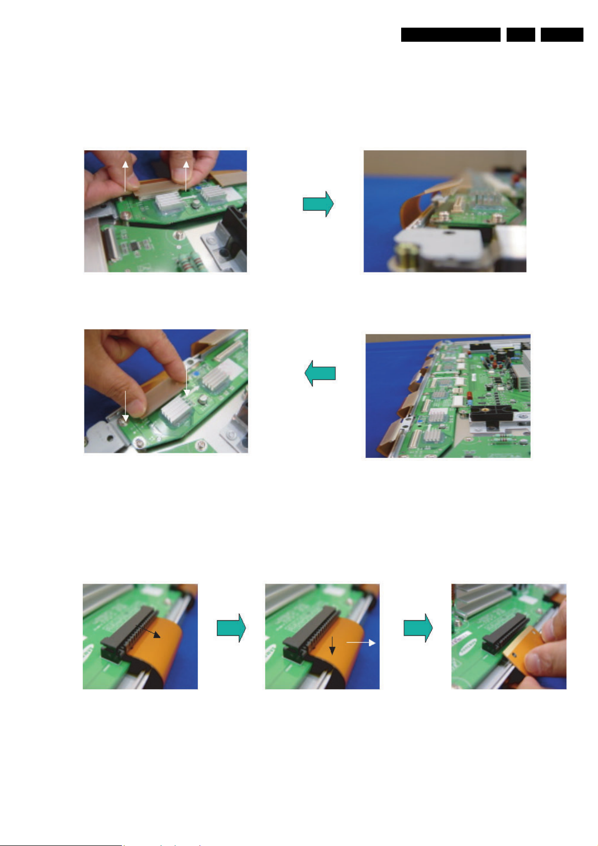
4.1.1 Disassembling & Re-assembling of FPC (Flexible Printed Circuit) and Y-Buffer (Upper and Lower)
1. Removal procedure
• Pull out the FPC from Connector by holding the lead of the FPC with both hands.
2. Assembling procedures
EN 9S/SD/HD 3.1 PDP 4.
• Push the lead of FPC with same force on both sides into the connector.
Notice: Be careful do not get a damage on the connector pin during connecting by mistake.
4.1.2 Assembling & Disassembling of Flat Cable Connector of X-main Board
1. Disassembling Procedure
• Pull out the clamp of connector.
• Pull Flat cable out press down lightly.
• Turn the Flat cable reversely.
EN 10 S/SD/HD 3.1 PDP4.
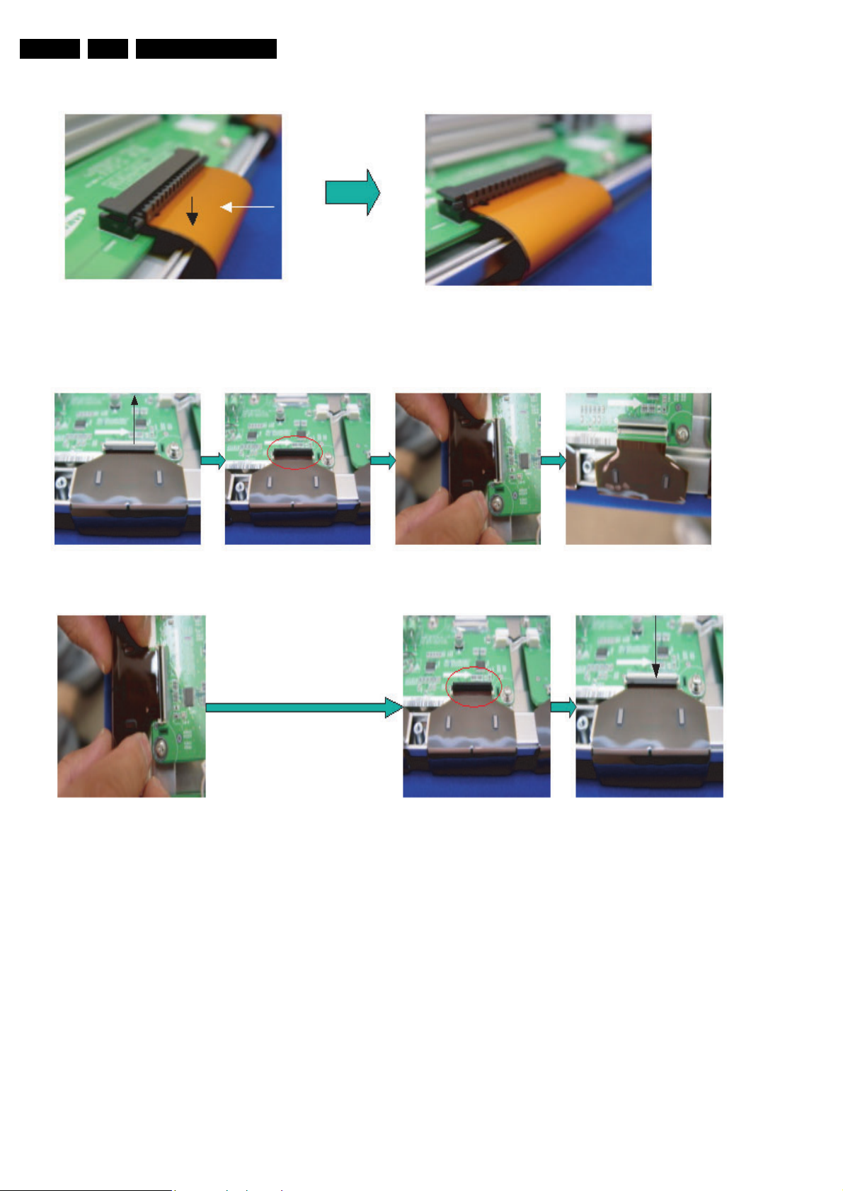
2. Assembling Procedures
• Put the Flat cable into the connector press down lightly until locking sound (“Click.“) comes out.
4.1.3 Assembling & Disassembling the FFC and TCP form Connector
1. Disassembling of TCP
Mechanical Instruction
• Open the clamp carefully. • Pull the TCP out from connector.
2. Assembling of TCP
• Put the TCP into the Connector carefully
• Close the clamp completely. (The sound “Click.” comes out.)
Notice:
• 1) Checking whether the foreign material is on the
Connector inside before assembling of TCP.
• 2) Be careful do not get a damage on the board by ESD
during handling of TCP.
3. Misassembling of TCP
• The misassembling of TCP is the cause of defect.
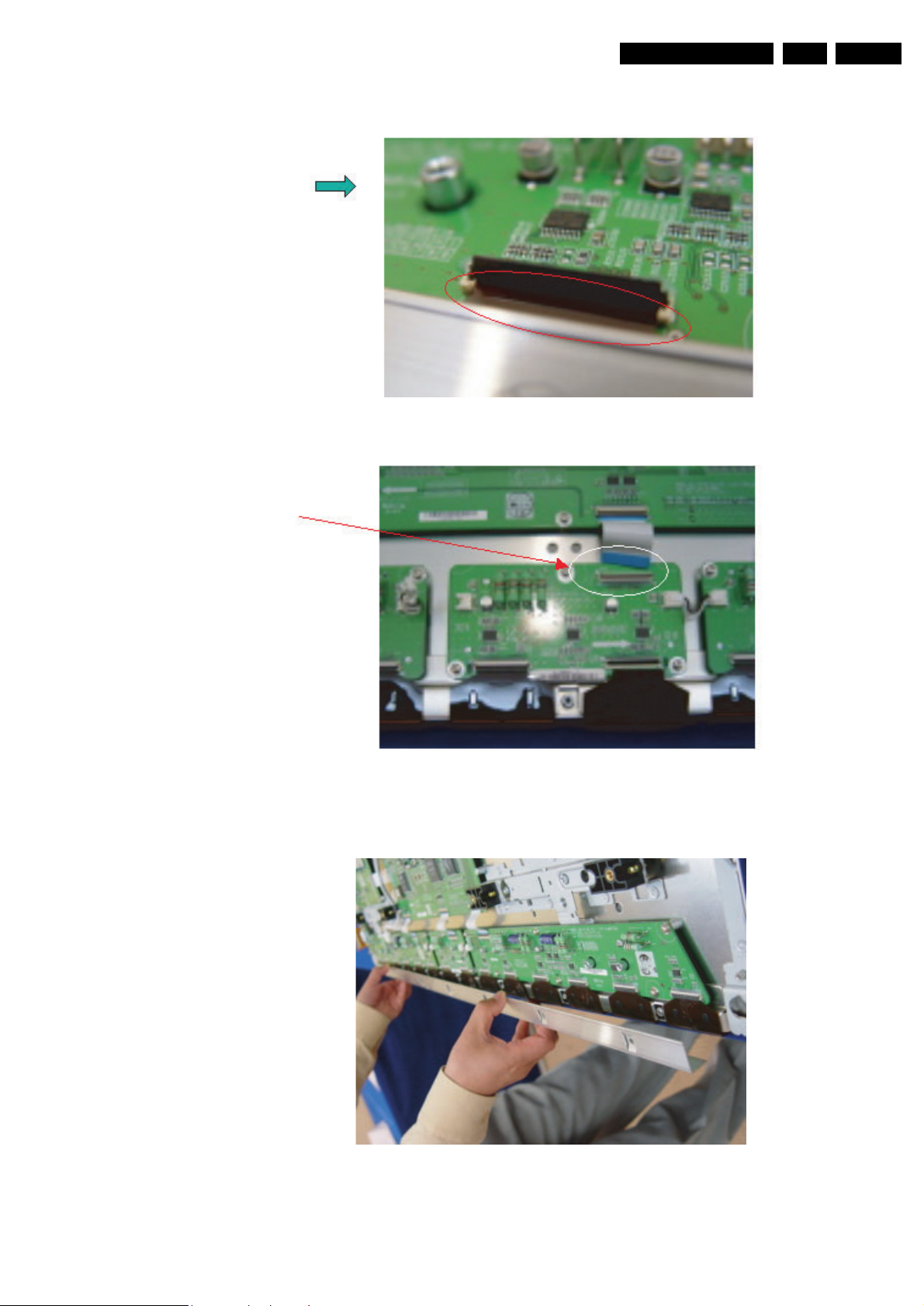
4. Assembling & Disassembling of FFC
The procedure of
assembling and disassembling of
FFC is same as TCP
Mechanical Instruction
EN 11S/SD/HD 3.1 PDP 4.
• This is the photo of the assembling of FFC.
4.1.4Exchange of LBE, LBF, LBG board
Photo 1
EN 12 S/SD/HD 3.1 PDP4.
Photo 2 - 42" SDv2
Mechanical Instruction
4617532
Photo 2 - 42" SDv3
4617532

Photo 2 - 42" HDv3
XYG Z[G \G]G ^_
Mechanical Instruction
EN 13S/SD/HD 3.1 PDP 4.
YY
Photo 2 - S37" SDv4
`XW XXXY X[G X\X] XZ
EN 14 S/SD/HD 3.1 PDP4.
Photo 2 - 50" HDv3
Mechanical Instruction
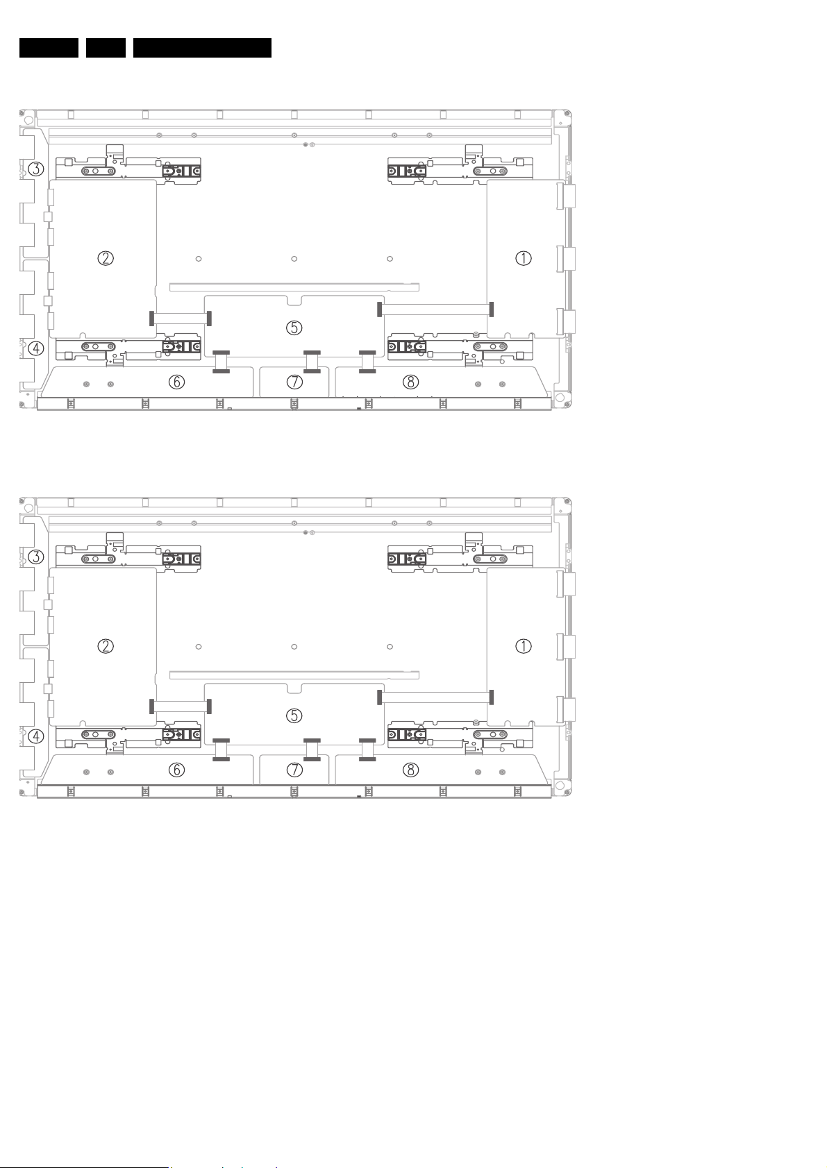
1. 42" SDv3 - Remove the screws in order of 2-3-5-7-1-4-6 and
10-11-13-16-9-12-14 for HD from heat sink and then get rid
of heat sink. (Photo 1)
42" HDv3, S37" SDv4, 50" HDv3
- Remove the screws in order of Center - Left Side - Right
Side from heat sink and then get rid of heat sink. (Photo 1)
2. Remove the TPC, FFC and power cable from the connectors.
3. Remove all the screws from defected board.
4. Remove the defected board.
5. Replace the new board and then screw tightly.
6. Get rid of the foreign material from the connector.
7. Connect the TCP, FFC and power cable to the connector.
8. Reassemble the TCP heat sink.
9. 42" SDv3 - Screw in order of 4-1-7-6-5-3-2 and 12-9-15-1413-11-10 for HD. (Photo 2) 42" HDv3, S37" SDv4, 50" HDv3
- Screw in order of Right Side - Left Side - Center (Photo 2)
If you screw too tightly, it is possible to get damage on the Driver IC of TCP.
4.1.5 Exchange YBU, YBL and YM board
1. Separate all the FPC connector of YBU (Y-Buffer upper) and YBL (Lower). (Photo 1)
2. Separate all the connector of CN5001 and CN5008 from YMain.
3. Loosen all the screws of YBU, YBL and YM.
4. Remove the board from chassis.
5. Remove the connector of CN5006 and CN5007 among YBU, YBL and YM.
6. Remove the YBL and YBU from Y-main.
7. Replace the defected board.
 Loading...