

Page 1

Circuit Descriptions, Abbreviation List, and IC Data Sheets
9. Circuit Descriptions, Abbreviation List, and IC Data Sheets
EN 95FTP1.1E 9.
Index of this chapter:
1. Introduction
2. Block diagram
3. Power supply
4. Input/Output (I/O)
5. Video Processing
6. Audio
7. Synchronisation
8. Control
9. Protections
10. PDP Panel
11. Software upgrading
12. Abbreviation list
13. IC Data Sheets
Notes:
• Only new circuits (circuits that are not published recently)
are described.
• For the other "known" circuits, see:
– EM5E manual. This manual is available under number
3122 785 12560 (= English).
– EM6E manual. This manual is available under number
3122 785 13070 (= English).
– FM24 manual. This manual is available under number
3122 785 12770 (= English).
• Figures can deviate slightly from the actual situation, due
to different set executions.
• For a good understanding of the following circuit
descriptions, please use the wiring, block and circuit
diagrams. Where necessary, you will find a separate
drawing for clarification.
• Where EBILD (Eagle Based Intelligent LCD Driver) is
mentioned, please note that the SW for this programmable
device is optimised for PDP.
Further features of the SSP are:
• The 3D Comb filter functionality (for USA) is integrated on
the SSP.
• The rear I/O connections (like SCART and cinch) are
integrated on the SSP, even as the tuner.
• VGA input (for Europe).
• DVI input (only for USA).
On the photographs you can see where all the functional cells
are located on the SSP:
9.1 Introduction
The FTP11 is a 42-inch integrated PDP flat screen set, which
uses the EM6 small signal panel. The HOP part is replaced by
an Erasable Programmable Logic Device (EPLD).
This chassis has no PIP, no FDW, and no TXT-DW. Also,
features like Dolby, DVD-loader, HDD, and/or radio are not
present.
In this chapter, the European version is described. In some
cases also the US version is described.
9.1.1 Features
This chassis has the following (new) features:
• Next step "Active Control" with: two new bars ("Motion" and
"Tint Control" bar), four split demos, etc.
• Small Signal Panel (SSP) that is based on the existing EM6
architecture: a full panel with integrated (shielded) Feature
Box as in the former MG-chassis. This approach gives
better EMC / crosstalk behaviour and less cables.
• Upgradeable main software (via ComPair).
9.1.2 Small Signal Panel
The SSP is a high tech module (four layer, 2 sides reflow
technology, full SMC) with very high component density and
partial shielding (FBX, EBILD) for EMC-reasons. Despite this,
it is designed in such a way, that repair on component level is
possible. To achieve this, attention was paid to:
• Clearance around surface mounted ICs (for replacing).
• Detailed diagnostics and fault finding is possible via
ComPair.
• Software upgrading is possible via ComPair.
Page 2

EN 96 FTP1.1E9.
Circuit Descriptions, Abbreviation List, and IC Data Sheets
TO PDP PANEL
LVDS
DC/DC CONVERTER
ADC
VGA/RGB
EPLD
VGA
ADC
ADC
LVDS
CINCH
(AUDIO)
PIXEL PLUS
FM2
FM3
2V5
FBX (2FH)
OTC HIP
FM5
3V3
CINCH
(EXT5)
OTC
MAIN
SW
FBX
SW
SCART
(EXT1/2)
AUDIO PROC.
DPL
MSP
XTL
HIP1
XTL
SCART
(EXT3/4)
DW/PIP
HIP 2
MUPPET
TUNER
I/O
HEADPHONE ANTENNA
SERVICE
CONNECTOR
IN
CL 36532075_049.eps
241103
TUNER
DW/PIP
Figure 9-1 SSP top view
DC/DC CONVERTER
AUDIO PROCESSOR FBX (2FH)
FMI
PICNIC
HIP
COMB
FILTER
I/O
OTC
FLASH
(EPG)
DRAM (TXT)
FALCONIC
PIXEL PLUS
DNM
FM4
EAGLE
VGA/RGB
ANTENNA
IN
SERVICE
CONNECTOR
HEADPHONE CINCH
SCART
(EXT 3/4)
SCART
(EXT 1/2)
(EXT5)
Figure 9-2 SSP bottom view
AUDIO
VGACINCH
CL 36532075_050.eps
171103
Page 3
Circuit Descriptions, Abbreviation List, and IC Data Sheets
9.2 Block Diagram
EN 97FTP1.1E 9.
CVBS 1
STATUS
EXT 1
FBL 1
TUN_CVBS
OUT
STATUS 2
Y/CVBS2
R2 C IN
EXT 2
B2 C OUT
FBL 2
Y/CVBS 2 OUT
CVBS 3
EXT 3
STATUS 3
Main Tuner
VIF OUT
Y/Cvbs ext 1/4 main
read_status 1
R1
G1
B1
read_status2
G2
From OTC
P50
cv
CIN
bs ext 3
rgb ext 1
YUV1fH
fbl ext 1
TUN_CVBS OUT
Y/CVBSrecordOut
G
D
cvbs
ter
cvbs int
cvbs 1
+
cvbs 2
y-cvbs 3
c3
y-cvbs 4
c4
FBL 1 in
FBL 2 in
rgb1
rgb2
IF
PIP
OUT
YYYCCC
SCART2
OUT
MAIN
OUT
yuv 1fh
HIP
MAIN
CVBS pip
out
+
PR
OC
+
CVBS PIP
OUTmain
YUV MAIN
Y
C
Comb control
CVBS txt out main
set_rgb_main
2FH/3FH
INPUTS
FBX
COMB
CVBS TXT
EBILD
LVDS
transmitter
PDP
A/D
VD
HD3
OTC
Status 3
Status 4
I2C
P50
to scart 2
Keyboard input
RGB
OTC
OTC
blanking
CL 36532075_046.eps
201103
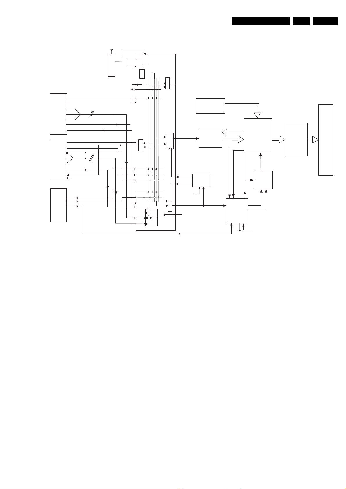
Figure 9-3 Block diagram FTP11
The main tuner is a PLL tuner and delivers the IF-signal, via
audio and video SAW-filters, to the main HIP (High-end Input
Processor). This HIP has the following functions:
• IF modulation.
• Video source select and record select (for 1fH inputs).
• Colour decoder.
• Synchronisation.
The following video input/output connections (with audio
connections) are available for Europe:
• Side: interfaces CVBS and Y/C.
• EXT1: interfaces CVBS, RGB-, and YUV-input (1fH)
• EXT2: interfaces CVBS and Y/C (meant for VCR or DVDR
connection).
• EXT3: interfaces CVBS.
• AV5: interfaces YPbPr (2fH/3fH).
• AV6: interfaces VGA (2fH/3fH).
The HIP delivers YUV and H/V-sync signals to the PICNIC (in
the Feature Box). This IC takes care of:
• Analogue to Digital conversion and vice versa.
• 100 Hz processing
• Interlaced to progressive scan conversion.
• Panorama mode.
• Noise reduction.
• Dynamic contrast.
After the PICNIC, the YUV-signals are fed to the FALCONIC for
"Natural Motion", followed by the Eagle for picture
enhancement. The processed YUV signals (from Eagle or
PICNIC) are, together with the sync-signals from the PICNIC,
then fed to the EBILD (Eagle Based Intelligent LCD Driver).
This programmed IC handles the video control. The RGBsignals for TXT/CC/OSD (from the uP) are also inserted via this
IC. The video part delivers the RGB signals to the PDP-panel.
The sound part is built around an MSP (Multi-channel Sound
Processor) for IF sound detection, sound control and source
selection. Amplification is done via a "class D" integrated power
amplifier IC, the TDA7490.
The microprocessor, called OTC (OSD, TXT/CC and Control)
takes care of the analogue TXT input processing and output
processing. The OTC, ROM, and RAM are supplied with 3.3 V.
The NVM (Non Volatile Memory) is used to store the settings;
the Flash-RAM contains the set software.
9.3 Power Supply
For Service this supply-panel is a black box.
When defect (this can be traced via error-codes in the error
buffer, or by strange phenomena), a new panel must be
ordered, and after receipt, the defective panel must be send for
repair.
In that case before sending it, check if the supply-output lines
match with the values on the PDP-sticker.
Page 4
EN 98 FTP1.1E9.
Circuit Descriptions, Abbreviation List, and IC Data Sheets
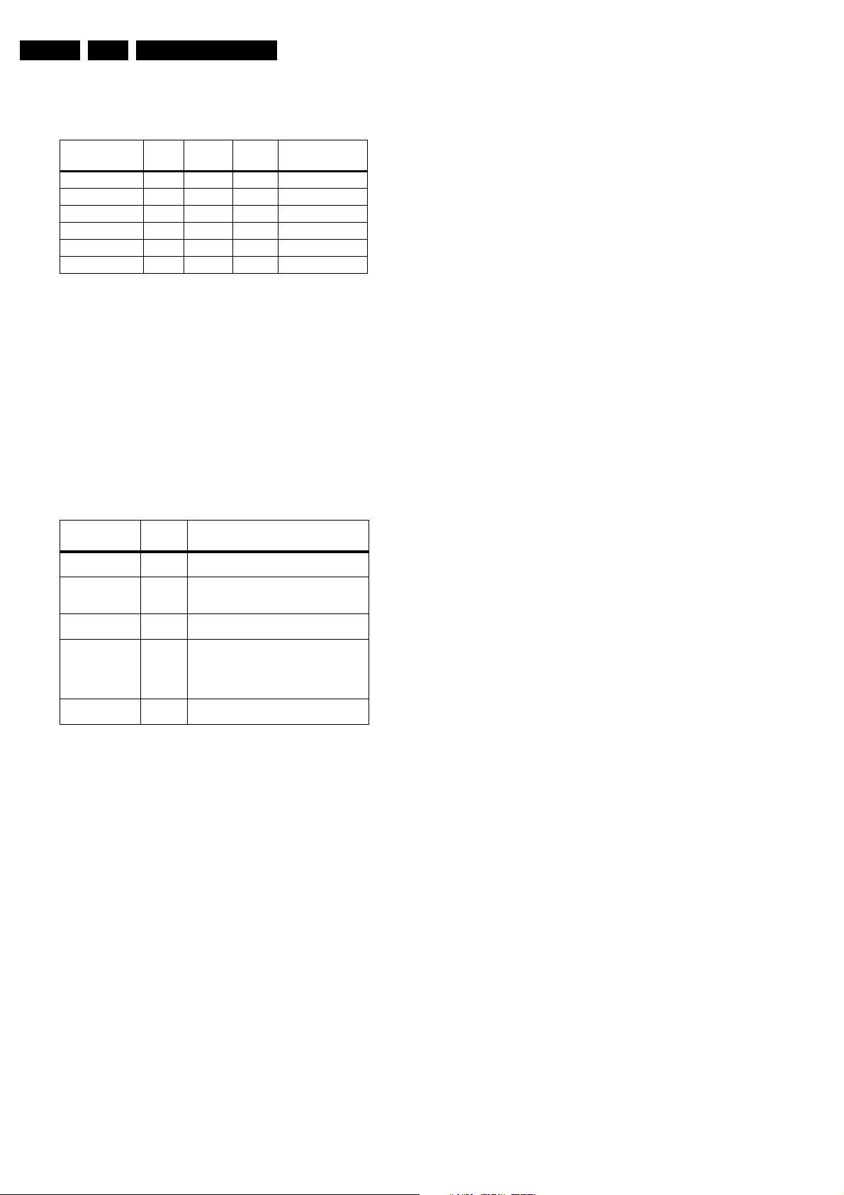
9.3.1 Power Balance
Table 9-1 Total power balance overview
Voltage Value Current
P_max Remarks
(max)
+3V3-DISP 3.3 V 3.6 12
+5V-DISP 5 V 0.8 4
+5V2-DISP 5.2 V 0.3 1.6 Standby voltage
+8V-DISP 8.6 V 0.4 3.4
+9V-STBY 9 V +9V-STBY-SW 9 V -
9.3.2 Switch On/Off
Via the ON/OFF knob on the side the set can be switched “on”
or “off”, although when “off” not all power is removed. Only by
disconnecting the mains power cord from the power socket all
power is really gone.
9.3.3 Power States
There are four different power states. Some characteristics of
these are summarised in the "Power states" table.
Table 9-2 Power states overview
On/Off
Power state
OUT (mainscord
disconnected)
OFF OFF Only standby supply is working OTC not
STAND BY (1) ON Standby supply is working Red LED is "on" (in
SEMI STAND BY ON Standby supply is working
ON ON The set is working Green LED is "on" (in
switch Remarks
XNo power
powered
Main supply not working No LED is "on"
Europe and in US)
Main supply is working PDP is not active EPG
loading and P50 recording possible (Europe)
Time extraction (Europe and US) Red and
Green LEDs are "on"
Europe and in US)
Events from OFF to SEMI-STANDBY or ON
(See also figure "Step wise start-up diagram" in chapter
"Service Modes, Error Codes, and Fault Finding").
1. The set is in "off" state until the ON/OFF switch is switched
to "on". The standby voltage +5V-DISP becomes available,
the OTC resets, the I/O pins are initialised, and the
watchdog is enabled. The set comes in standby mode.
– The sets leaves the stand by mode if:
– A time extraction must be started (after every start up).
– A P50 recording has to start.
– An EPG loading has to start.
– The Standby bit is set to "off"; when a user switches on
the set, the standby bit is also set to "off".
2. The STANDBY line is set to "low", the +5V_SW is "on", the
relay closes, and the LCD AUX supply starts up (8V6 is
present).
3. The rest of the ICs are initialised. The EBILD is initialised
min 400 ms after the standby line is set to "low".
4. If the standby bit was set, the set goes into semi-standby
until:
– The time extraction is done.
– The P50 recording has finished.
– The EPG loading has finished.
5. If the standby bit was not set, the PDP is switched "on". The
PWR-OK-PDP signal from the supply is received at the
EBILD to inform the main processor of proper operating
PDP supply.
Events in SEMI-STANDBY
1. The set can be in semi-standby during Time extraction,
EPG loading, or P50 (Easylink) recording. The semistandby state is ended when:
– Time extraction has finished.
– P50 recording has finished.
– EPG loading has finished.
– A P50 recording starts during EPG loading.
– A user event "On" or "Standby".
– The set goes into protection.
2. If the standby bit is not set (after user event), the PDP is
switched "on".
3. If a P50 recording or an EPG loading has to start, the set
stays in semi-standby. If the P50 recording has to start
during EPG loading, the P50 has priority.
4. If there is no P50 recording or EPG loading, the set goes to
standby.
Events from ON to SEMI-STANDBY/STANDBY
1. The set can be switched to standby:
– Via the RC (to semi-standby).
– Via the MENU button on the top control, long press (to
semi stand by).
– Via a protection (to standby).
2. The running instructions are finished.
3. The PDP is switched "off"; this is controlled by the OTC by
means of the STANDBY line.
– Sound is muted
– If there was a protection, the STANDBY line is put
"high", and the set goes to standby.
4. If there was no protection, the set goes to semi-standby.
5. After an event in semi-standby, the set goes to standby.
6. Protections are disabled.
7. The OTC sets the STANDBY line "high", this switches "off"
the main power supply, and only the standby supply
remains working.
8. The set is in standby.
9.4 Input/Output (I/O)
9.4.1 Introduction
The chassis follows the standard SCART specification:
• The presence of the incoming source is detected via pin 8
of the SCART signal.
• The Aspect Ratio of the incoming source is derived from
the voltage level on SCART pin 8. The pin 8 information is
handled by the HIP for SCART 1 and 2 and by the OTC for
SCART 3.
• The P50 in/out is handled via P1-4 and P3-7 of the OTC.
• RGB sources break in with an additional fast blanking
signal that is detected by the HIP. The HIP then internally
chooses other signal processing. RGB sources that only
have fast blanking and no pin 8 status do not overrule the
main TV source. There is no automatic break in detection
for the front input.
• The HIP for further image processing does the detection
between Y/C and CVBS automatically.
• When Y/C is detected, the HIP will add Y and C signal to
compose CVBS again. This addition should be overruled
by software at the moment any Y/C signal is the source and
the presence of a P50 Y/C video recorder is detected: only
Y signal is directed to record out (C is already hardwired to
EXT 2 out).
Note: P50: Chroma-out is pin 7, Chroma-in is pin 15. NonP50: both Chroma-out and -in is pin 15 (hardwiring C to pin
7 out; non-P50 not supported).
• The signal on MONITOR_OUT follows the incoming
source, except in case the incoming source is EXT2,
YPbPr-2fH, or VGA. Then the output signal should be
FRONTEND_OUT.
Page 5
Circuit Descriptions, Abbreviation List, and IC Data Sheets
Note: The SCART input (1fH) path is equal to the one
described in the EM6E manual. Therefore, it is not described in
much detail here.
9.4.2 Input detection
The RGB or YPbPr input signals (2fH/3fH) are sent to the ADC
(AD9883A) together with H and V pulses from DVI (USA) or
VGA (EUR), and the Y signal from YPbPr called Sync On
Green (green is same line as Y). The AD converter:
• Detects via H and V sync, if RGB is present or not.
• Detects via Sync On Green, if YPbPr is present or not.
• Detects the selected sync.
• Selects the sync switch via I2C.
• Does AD conversion to 848 samples per line, 8 bits in 422
format. This means one bus for Y signal with 8 bits and one
bus for UV with 4 U and 4 V bits. Depending on the system
detected by EBILD, the sample frequency is changed. Via
I2C, the "PLL_DIV" signal is given in 11 bits (2 Bytes).
When a 1fH input is detected, the AD converter is set in tristate.
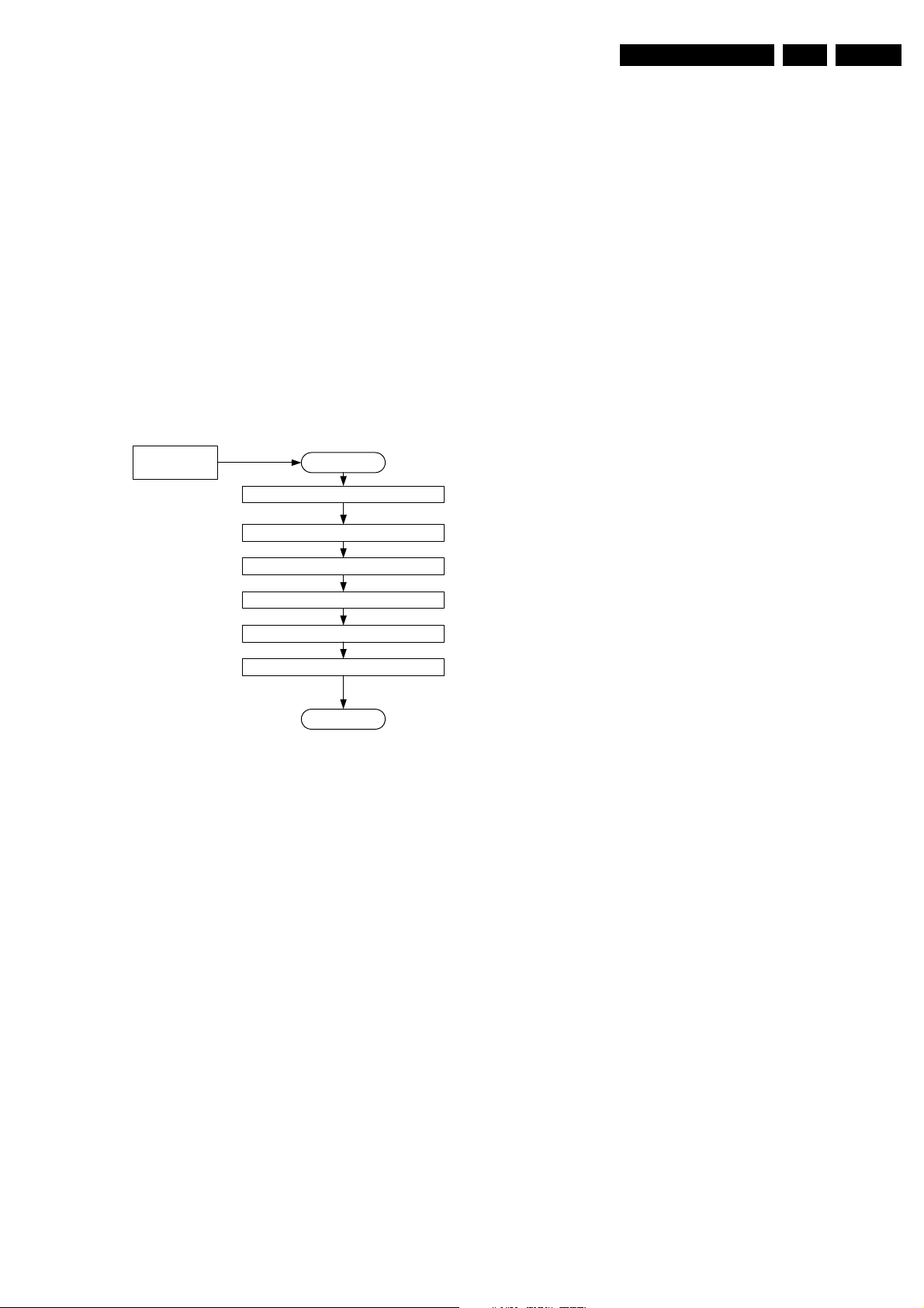
1fH input flow
START1Fh selection
Mute sound, Blank picture
EN 99FTP1.1E 9.
Put ADC: power down
Put PICNIC: freerun OFF
Set FBX, see lookup table
Set EBILD, see lookup table
Demute sound, Unblank picture
1FH
CL 36532053_080.eps
170703
Figure 9-4 Flowchart 1fH detection
1. If a 1fH selection is done (except for AV4 in USA), the
sound is muted and the picture is blanked.
2. The ADC is powered down.
3. The PICNIC is not in free run.
4. Both FBX and EBILD are set in 1fH (see lookup table).
5. Sound is demuted and picture is unblanked.
Page 6
EN 100 FTP1.1E9.
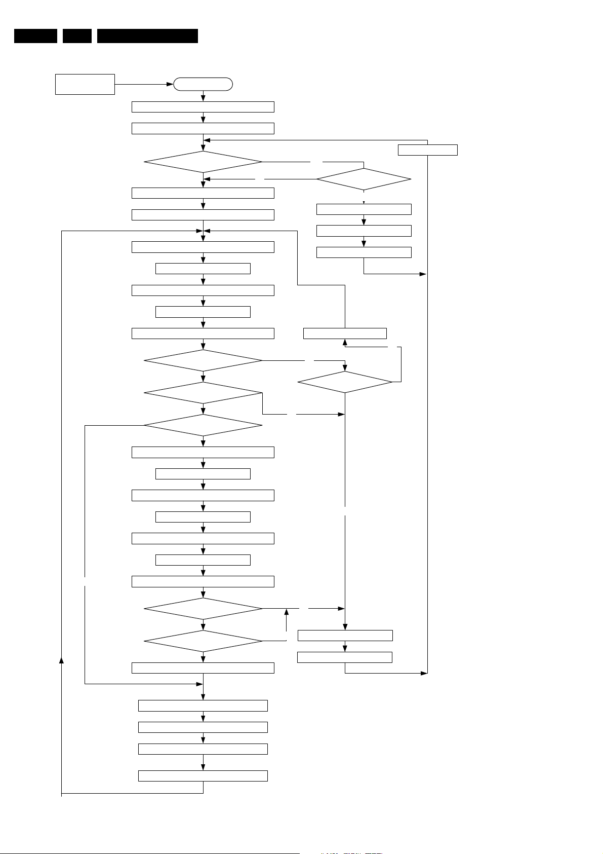
2fH/3fH input flow
AV5 or AV6 Eur
AV4 or AV5 US
Selection
Circuit Descriptions, Abbreviation List, and IC Data Sheets
START
Put ADC: full power
Mute sound, Blank picture
AV4 on US ?
wait 200 msec
yes
no
Put picnic: freerun ON
Put ADC on last status from select. input
get Ebild: samples/line, lines/field=STDET1
wait >20 msec
get Ebild: samples/line, lines/field=STDET2
wait >20 msec
get Ebild: samples/line, lines/field=STDET3
STDET1=2=3?
yes
Supp standard ?
yes
same standard as last status?
no
Set ADC, see tookup table
no
1Fh detection in HIP?
yes
Put picnic to 1FH
Put picnic: freerun OFF
Unblank, demute
Set ADC to default value
no
no
ADC to default value ?
no
yes
wait >20 msec
get Ebild: samples/line, lines/field=STDET1
wait >20 msec
get Ebild: samples/line, lines/field=STDET2
wait >20 msec
get Ebild: samples/line, lines/field=STDET3
STDET1=2=3?
yes
Supp standard ?
yes
Store standard as last status selected input
Set FBX, see lookup table
Set EBILD, see lookup table
Unblank, demute
yes
no
no
set Ebild: blue mute
OSD: Message
wait: 200 msec
Figure 9-5 Flowchart 2fH/3fH detection
CL 36532053_079.eps
160703
Page 7

Circuit Descriptions, Abbreviation List, and IC Data Sheets
EN 101FTP1.1E 9.
1. The standard detection starts with a 2fH/3fH selection (this
is AV5 / AV6 in Europe or AV4 / AV5 in USA).
2. The ADC is full powered (it was powered down in 1fH).
3. The sound is muted and the picture is blanked.
4. On AV4 in USA, an 1fH and 2fH/3fH signal can enter. This
detection is done by the HIP. When 1fH is detected, the
FBX is set to 1fH, the PICNIC is not in free run, the picture
is unblanked, and the sound is demuted. The set is in 1fH
state. This state is continues checked, because the input
can change from 1fH to 2fH/3fH.
5. If the input is 2fH/3fH, the PICNIC is set to free run
6. The ADC is set to the last status from this selected input,
because there is a big chance that the same standard is
wanted.
7. The number of samples per line and lines per field is
collected from the EBILD. The check is done three times. If
the same value is measured within some tolerances (see
lookup table) the standard is valid. The time between two
measurements must be at least one frame or 20 ms.
Table 9-3 I/O lookup table
Selected Input Standard x fH FBX ADC EPLD Field Rate
Tuner, SC1..SC3. 480i 1 fH PICNIC
576i 1 fH PICNIC
AV5 (Cinch) 480p 2 fH EAGLE YPbPr YPbPr 60 Hz
576p 2 fH EAGLE YPbPr YPbPr 50 Hz
1080i / 60 Hz 2 fH EAGLE YPbPr YPbPr 60 Hz
1080i / 50 Hz 2 fH EAGLE YPbPr YPbPr 50 Hz
720p / 60 Hz 3 fH / 720p EAGLE YPbPr YPbPr
720p / 50 Hz 3 fH / 720p EAGLE YPbPr YPbPr
AV6 (VGA) 480p 2 fH EAGLE RGB 60 Hz
576p 2 fH EAGLE RGB 50 Hz
1080i / 60 Hz 2 fH EAGLE RGB 60 Hz
1080i / 50 Hz 2 fH EAGLE RGB 50 Hz
720p / 60 Hz 3 fH / 720p EAGLE RGB
720p / 50 Hz 3 fH / 720p EAGLE RGB
VGA 2 fH EAGLE RGB 60 Hz
SVGA 2 fH EAGLE RGB 56 Hz
8. If the ADC has not the right settings, the PLL does not lock,
and the "STDET" measurements do not give the same
results. The ADC is set to its default value; this value is able
to catch all supported standards. If the ADC is already in
the default value and no standard detection is possible, the
set changes to blue mute.
9. If the standard is not supported, the set changes to blue
mute via the EBILD, and a message is displayed.
10. If the standard is the same as the last status, the ADC is in
the correct state, an both FBX and EBILD are set (see
lookup table).
11. If the standard is changed, the ADC is set to the detected
standard and a new check is done. If the standard is valid
and supported, the new standard is stored in NVM as last
status.
12. The FBX and EBILD are set (see lookup table)
13. Picture is unblanked and sound demuted.
9.5 Video Processing
9.5.1 Introduction
Note: The FBX processing part is equal to the one described
in the EM6E manual. Therefore, it is not described here (except
for some basic info).
There are two diversities (see also figure "Block diagram
FTP11" in paragraph "Block Diagram"):
• Europe: 3 SCARTs, 1 x 2fH/3fH inputs (YPbPr), and 1 VGA
input
• USA: 3 AV inputs1 (AV4 can be 1fH or 2fH/3fH YPbPr), and
a DVI 2fH/3fH input.
Note: There is also an AP version available. This version has
no difference w.r.t. the European version, but comes with extra
cables and some different option settings.
Short overview of video processing
The video processing is based on four key functions, being:
• The HIP + comb filter (for simple source select and video/
chroma processing).
• The EBILD that takes over the video control functions of
the HOP (as used in CRT based sets).
• The FBX configuration consisting of a PICNIC (100 Hz
featuring), a FALCONIC (motion compensation and Auto
TV featuring), and an EAGLE ("Pixel Plus" processing).
• A 2fH/3fH source selection.
Additionally, the following features are added
• One-chip NEC 3D comb filter (only for USA): this comb
filter uses spatial and temporal filtering for the elimination
of cross colour and cross luminance components. Not only
for vertical lines, but also for stationary diagonal lines. This
comb filter only supports the NTSC standard.
• The light sensor measurement required for "Active Control"
is done by the OTC.
Basic functionality of HIP
I/O functionality
• The HIP selects the signals entering on 1fH base band.
The HIP contains a source select matrix in order to handle
a Tuner, three CVBS sources, two Y/C sources, and two
RGB inputs (this in fact means one VIF input for tuner, four
CVBS inputs with among them two Y/C inputs, and two
RGB inputs). The HIP detects by itself whether the source
is Y/C or CVBS, and decides how to handle the signal for
further image processing. For Record Out, the signal is
handled by software: if a P50 SVHS VCR is present and
the signal to be recorded is Y/C, an Y/C signal should be
passed to the VCR.
• There are also two inputs for the OTC that will handle
status detection, other, or more detection. In case of RGB,
the fast blanking signal (FBL) determines the breakthrough of the RGB1/YPbPr signal if activated beforehand
by the user. If a YPbPr-1fH connection was done, then it is
equally handled by the RGB1 input without using the
internal matrix. The HIP delivers the main video output
(YUV- 1fH signal) for further image processing and three
Page 8

EN 102 FTP1.1E9.
Circuit Descriptions, Abbreviation List, and IC Data Sheets
CVBS outputs, being: CVBS PIP/DS, CVBS_TXT_OUT for
comb filter (always following YUV main!) and TXT
processing, and the CVBS/Y_RECORD_OUT for EXT2.
IF functionality
• The HIP contains a multi standard IF circuit for video
demodulation with AFC functionality, a sound IF amplifier,
and an AM demodulator. An extra group delay correction is
included.
• Chroma demodulation and video processing
• Sync acquisition, delivering H_A/V_A (Horizontal/Vertical
Acquisition) towards FBX.
Basic functionality of EBILD
The EBILD is the interface between the FBX and the PDP
screen. Its principal functions are:
• Video control functions of the HOP (Saturation, Contrast,
Brightness).
• OSD and TXT insertion with blending.
• Video Matrix (NTSC, ATSC, PAL).
• For matrix displays additional functions like:
9.5.2 Video Source Selection
Table 9-4 Video input overview
– Contrast reserve (peak limiter),
– Sync wheel,
– Dithering (matrix displays are 8 bit),
– Generation of correct timing for PDP display.
• I2C and SNERT bus.
• Sync control.
• Odd/Even field detection.
• A/D converter alignment for OSD.
• H Sync generation for OTC.
• Control lines.
• Standard detection.
• Handle shifts of VD.
• Suppress H and V pulses in active video.
• Generate a H_REF for PICNIC (1fH) in case of a 2fH/3fH
source.
Basic functionality of the OTC
The OTC combines the microprocessor and TXT/OSD
functionality; it will also handle some of the status detections. It
also takes care of P50 communication.
I/O
EXT1 SCART Main Yes Yes, frontend No No Yes No No No Yes No
EXT2 SCART Main Yes Yes, WYSIWYR Yes Yes Yes No No No Yes Yes
EXT3 SCART Main Yes No No No No No No No Yes No
AV5 cinch Main No No No No No Yes Yes No Only video det. No
AV6 VGA Main No No No No No No No Yes Only video det. No
The High Definition Input (HDI) part has two input "ports". Each
port consists of a video input and an audio input. The ports are
named "VGA" (= AV6) and "AV5" and will be referred to using
these names.
The physical connectors for these inputs are:
• AV5. Three cinches that can be used for YPbPr with sync
on Y and two cinches for analogue Audio (left and right).
• VGA. One VGA connector and two cinches for analogue
Audio (left and right).
Table 9-5 AV5 (YPbPr) input signals
AV5 Inputs
(YPbPr)
576 p PAL 50 Hz 31.25 kHz
480 p NTSC 60 Hz 31.5 kHz
1080 i ATSC 60 Hz 33.7 kHz
1080 i ATSC 50 Hz 28.125 kHz
720 p ATSC 50 Hz 37.5 kHz
720 p ATSC 60 Hz 45 kHz
Main/Sub
CVBS-in
Sub Yes n.a. No n.a. No No No No Yes No
Sub Yes n.a. Yes n.a. Yes No No No Yes Yes
Sub Yes n.a. No n.a. No No No No Yes No
Sub No n.a. No n.a. No Yes No No Only video det. No
Sub No n.a. No n.a. No No No No n.a. No
System Field freq.
(V)
CVBS-out
Line freq.
(H)
Y/C-in
Y/C-out
RGB 1fH+ FBL
YPbPr 1fH
YPbPr 2fH/3fH
RGB 2fH
Status 4/3-16/9
P50
Page 9

Circuit Descriptions, Abbreviation List, and IC Data Sheets
Table 9-6 AV6 (VGA) input signals
EN 103FTP1.1E 9.
AV6 Inputs
System Field freq. (V) Line freq. (H)
(VGA)
VGA 640x480 60 Hz 31.5 kHz
SVGA 800x600 56 Hz 35.1 kHz
576 p PAL 50 Hz 31.25 kHz
480 p NTSC 60 Hz 31.5 kHz
1080 i ATSC 60 Hz 33.7 kHz
1080 i ATSC 50 Hz 28.125 kHz
720 p ATSC 50 Hz 37.5 kHz
720 p ATSC 60 Hz 45 kHz
9.5.3 Video Processing
USA
DVI
EUROPE
VGA
Y Pb Pr
SILICON
EPROM
H-SYNC-DVI
V-SYNC-DVI
RGB
H-SYNC- VGA
V- SYNC-VGA
Matrix RGB
YUV
Y(SOG )
TDA8601
Video
SW
AD9883A
A/D
EPL D
Y -2FH -0...7
U-2FH- 0...7
V- 2FH-0 ...7
UV-2FH-0...7
Y -2FH -0... 7
FM
FM
Y
U
V
FM
Falconi cPicnic
Figure 9-6 Video processing 2fH/3fH input
The outputs toward the electronics of the set consist of:
• YUV-422.
• H-2FH-AD-OUT and V-2FH-AD-OUT.
• Left and right audio channels (analogue).
• CLK-2FH.
Notes:
• In case of 2fH inputs, the signal is (after detection via the
EBILD) routed through the FBX for picture improvement.
The YUV output of the Eagle is then routed to the EBILD
for the displaying part.
• In case of 3fH inputs, the signal is not routed via the FBX
(because the Eagle cannot handle them), but directly
processed by the EBILD.
9.5.4 Miscellaneous
Comb Filter
The comb filter functionality can be enabled or disabled via the
HIP. This means allowing or disallowing the HIP to use the
SCL-F3
SDA-F3
YOUT(0.. .9)
U_VOUT (0...9 )
TRISTA
TE
UVF
Y-2FH-0...7
UV-2FH-0...7
YF
BUFF
BUFF
YF-BUFF
UVFBUFF
BU FF
FM
(lower lines )
BU FF
FM
(upper l ines)
Eagl e
UV demux
Contr ast
satura tion
bright ness
DS90C385
LVDS Transmitter
LVDS Connector
PDP
YUV
to
RGB
Contra st Res erve
AD A lignment
RGBBL-
OS D
insert ion
FDB-0...3
RGBBL-OSD
RGBBL-
TDA9805
A/D
CLK-OSD
OSD-0...5
OTC
CL 36532075_047.eps
201103
comb filter. Both the conventional 2D comb filter (EUR) and the
3D comb filter (USA) have to use this HIP command.
Notes:
• The command ENABLE_COMBFILTER enables the
function. If the TV standard that enters the TV is one where
a comb filter is applicable (e.g. PAL or NTSC, not SECAM),
the HIP will determine self if the video signal can be
combed and as a consequence, the video processing
output can be CVBS or Y/C. No software interaction is
needed.
Remark: Enabling the comb filter does not necessarily
mean that the signals will be combed.
• The comb filter must be disabled in case of RGB and for
YPbPr-1fH, to avoid big horizontal shifts of the picture
caused by the comb filter processing.
• The comb filter is also disabled at very low quality antenna
signals for AP due to vertical instability/scrolling effects.
Page 10

EN 104 FTP1.1E9.
Circuit Descriptions, Abbreviation List, and IC Data Sheets
Auto TV
The Auto Picture Control or in short AutoTV, aims at providing
the customer the best possible picture performance at any
time. Therefore, it performs real time processing of the video
signal and because of that, it decides to adapt several video
parameters throughout the whole chassis. The total effect of
Auto Picture Control on the screen can be selected by the use
of the remote control. The commercial name for the feature is
"Active Control".
The sets have three digital options: Progressive Scan, Pixel
Plus, and Movie Plus. The Progressive Scan mode has no
Pixel Plus enhancement. For 2fH inputs, only Progressive
Scan or Pixel Plus mode can be selected. For 3fH inputs no
digital options are available.
The aim of Movie Plus mode is to reduce the Halo artefacts
(halo's are artefacts introduced with the Natural Motion
feature). Reducing halo's will result in motion judder. This is
compensated by the FBX software.
The basic component for Auto TV is the FBX. It measures the
picture content and it has the most video control parameters on
board, like peaking, coring, DNR, and so on. With the presence
of the Eagle, additionally the colour enhancement functions
and the LTI are controlled. Also, the light sensor, needed for
ambient light control, is supported via the OTC. Finally, vertical
peaking is mostly done in Eagle, a little in the PICNIC, and the
motion compensation and DNR is done in the FALCONIC.
See also EM5 service manual.
9.6 Audio
9.6.1 Introduction
In this chassis, there are only Virtual Dolby sets, but there is
diversity between Europe and USA sets.
9.6.2 Audio decoding
Two audio decoders will be used:
• ITT MSP 3411: for Europe sets.
• ITT MSP 3421: for USA sets.
Both MSP versions also decode NICAM. The AM signal is also
decoded by the MSP.
9.6.3 Audio source selecting
AUDIO BLOC K DIAGRAM EUROPE
12
AV5(Ypbpr)
6
Side/VGA
5
4
SC4
SC3
3
2
SC2
1
SC1
C in
MAIN HIP
3
TEA6422D
0X98
MAIN IN
SIF/AM
I2S
SC1
SC2
SC3
SC4
MSP3411
ENC
DE
C
DEC
DEC
MON OUT
REG-SW
AUX OUT
NSM4556
FTV lipsync
delay
1S01
L/R LS
MON OUT
FRONT OUT
Headphone
CL 36532053_077.eps
SCART 1
SCART 2
• For USA:
– AV1.
– AV2.
– AV4 (YPbPr 1fH or 2fH/3fH).
– AV5 (DVI).
There are three separated outputs on the matrix IC, but only the
main output (MAIN_IN), going to the MSP, is used.
The MSP has the following inputs:
• SIF input (this can be FM, AM, or NICAM).
• MAIN_IN from matrix IC TEA6422D.
• Centre input.
An S/PDIF in/output is not foreseen.
9.6.4 Audio processing
European sets have an MSP3411, USA sets have an
MSP3421. Both can handle Virtual Dolby. All sets have 2 x 10
W_rms output.
Following outputs are foreseen:
• Europe:
– EXT1: Front-end
– EXT2: WYSIWYR.
– Monitor out: for external Dolby ProLogic amplifier.
– Headphone out.
• USA:
– Monitor out: Front-end.
– Headphone out.
Important remarks
• For Europe: Régimbeau switch (REG_SW): this switch
(item 7I20) is needed to prevent feedback (Larsen effect).
When EXT2 is chosen as incoming signal, the output of
EXT2 following the main picture, is also EXT2. This will
cause the Larsen effect. To prevent this, the record select
must be switched to tuner. This is especially important
when decoders are used (e.g. Canal + decoder) behind a
"transparent" VCR connected to EXT2.
• It is not allowed to mix up analogue and digital signals in
the MSP; SCART-in towards SCART-out should be treated
in the analogue source select part of the MSP. Reason for
this, is the limited bandwidth in the MSP (16 kHz) while the
analogue source selection part can carry up to 20 kHz.
• If a 2fH/3fH source is selected, it is not possible to handle
the video signal in the 1fH source selection. Since the
video signal cannot be connected to EXT2, the output of
EXT2 is switched to FRONTEND, and MONITOR OUT is
WYSIWYR (same source as video).
181103
Figure 9-7 Audio block diagram
The MSP covers a SIF input, 4 stereo inputs and one mono
input. As this chassis needs more inputs, one matrix IC
(TEA6422D, item 7I17) is added. The stereo inputs on this IC
are:
• For Europe:
– EXT1.
– EXT2.
– EXT3.
– AV5 (YPbPr 2fH/3fH).
– AV6 (VGA).
Page 11

Circuit Descriptions, Abbreviation List, and IC Data Sheets
EN 105FTP1.1E 9.
9.6.5 Audio Amplifier Panel (Diagram A)
Introduction
TWEETER LEFT
TWIN-CONE SPEAKER LEFT
AUDIO AMPLIFIER
L-POS
L-NEG
R-POS
R-NEG
AUDIO
ENABLE
SSP
7225-A
7225-B
63Hz
AUDIO
AMPLIFIER
MUTE
PSU
7260-A
L-HIGH
HPF
7238-A
L-LOW
LPF
7260-B
R-HIGH
HPF
7238-B
R-LOW
LPF
1kHz 3kHz
LOW
HIGH
(LPF)
(HPF)
TWEETER RIGHT
TWIN-CONE SPEAKER RIGHT
MUTE
MUTE
MUTE
MUTE
6dB/OCT
Figure 9-8 Block diagram Audio Amplifier
This panel houses the audio filters and amplifiers necessary for
driving the speakers. The differential audio inputs (for common
mode immunity) come from the SSP (via connector 0388).
The PSU delivers the positive and negative supply voltage of
12 V_dc, as well as the +5V2 (standby) voltage.
After being filtered and amplified, the signals go to the speaker
section, where the (twin cone) low/mid range speakers and the
tweeters are driven (load impedance is 8 Ω).
The headphone amplifier is a straightforward OpAmp amplifier
(IC7A07-A, MC33178D). It is supplied with +11V_AUD.
Supply (Diagram A7)
The supply voltage is a symmetrical voltage of +/- 14.5 V_dc,
generated by the main supply via L5002.
• V_SND_POS (+12 V_dc) on connector 0302 pin 5/6.
• V_SND_NEG (-12 V_dc) on connector 0302 pin 1/2.
Filter (Diagram A2)
Electrical filtering is needed for following reasons:
• Limiting the cone excursion, thereby reducing the
distortion.
• Increasing the power handling capacity (PHC).
Active second order Sallen-Key filters are used, with crossover
frequencies of 1 kHz for the low pass filter, and 3 kHz for the
high pass filter.
The audio signals are filtered before the amplifier. There are
some reasons for doing this:
• It is now easy to do active filtering.
• Less costs (no expensive coils and capacitors).
L
HIGH LEFT
MID/LOW LEFT
R
HIGH RIGHT
MID/LOW RIGHT
CL36532053_081.eps
170703
High Pass Filter (HPF)
For L and R separately, a High Pass Filter (IC7260A and B) is
processing L_HIGH and R_HIGH.
The output signal of this filter is then fed to the audio amplifier
(identical for right channel).
Amplifier (Diagrams A3 to A6)
Each speaker has its own class-D amplifier. These amplifiers
combine a good performance with a high efficiency, resulting in
a big reduction in heat generation.
Principle
Audio-power-amplifier systems have traditionally used linear
amplifiers, which are well known for being inefficient. In fact, a
linear Class AB amplifier is designed to act as a variable
resistor network between the power supply and the load. The
transistors operate in their linear region, and the voltage that is
dropped across the transistors (in their role as variable
resistors) is lost as heat, particularly in the output transistors.
Class D amplifiers were developed as a way to increase the
efficiency of audio-power-amplifier systems.
+V
-V
CL16532099_002.eps
200801
Figure 9-9 Principle Class-D Amplifier
The Class D amplifier works by varying the duty cycle of a
Pulse Width Modulated (PWM) signal.
By comparing the input voltage to a triangle wave, the amplifier
increases duty cycle to increase output voltage, and decreases
duty cycle to decrease output voltage.
The output transistors (item 7365 on diagram A3) of a Class D
amplifier switch from 'full off' to 'full on' (saturated) and then
back again, spending very little time in the linear region in
between. Therefore, very little power is lost to heat. If the
transistors have a low 'on' resistance (R_DS(ON)), little voltage
is dropped across them, further reducing losses.
A Low Pass Filter at the output passes only the average of the
output wave, which is an amplified version of the input signal.
In order to keep the distortion low, negative feedback is applied
(via R3308). A second feedback loop (via R3310) is tapped
after the output filter, in order to decrease the distortion at high
frequencies.
The advantage of Class D is increased efficiency (= less heat
dissipation). Class D amplifiers can drive the same output
power as a Class AB amplifier using less supply current.
The disadvantage is the large output filter that drives up cost
and size. The main reason for this filter is that the switching
waveform results in maximum current flow. This causes more
loss in the load, which causes lower efficiency. An LC filter with
a cut-off frequency less than the Class D switching frequency
(350 kHz), allows the switching current to flow through the filter
instead of the load. The filter is less lossy than the speaker,
which causes less power dissipated at high output power and
increases efficiency in most cases.
Low Pass Filter (LPF)
For L and R separately, a Low Pass Filter (IC7238A and B) is
processing L_LOW and R_LOW.
The output signal of this filter is then fed to the audio amplifier
(identical for right channel).
Mute (Diagram A3 for "Left High")
A mute switch (item 7302) is provided at the PWM inputs (item
7315, LM311). This switch is controlled by the AU_EN_NOT
line, which is controlled via the POR signal (mute at start-up)
and via the SOUND_ENABLE line from the OTC (mute during
operation). This circuitry is the same for all four amplifier parts.
Page 12

EN 106 FTP1.1E9.
Protections
Short-circuit Protection (e.g. Diagram A3 for "Left High")
A protection is made against a too high temperature of
transistor 7355 in case of a short-circuit of output FET 7365-1.
Transistor 7340 is sensing the current through transistor 7355
via R3355, and activates the DC-protection line (see below) in
case the current becomes too high. This is the same for all four
amplifier parts.
DC-protection (Diagram A7)
+9V_STBY
5753
OUT_LH
OUT_LL
3770
3771
A
3780
3781
OUT_RH
OUT_RL
Figure 9-10 DC Protection
Because of the symmetrical supply, a DC-blocking capacitor,
between the amplifier and the speaker, is not necessary.
However, it is still necessary to protect the speaker for DC
voltages.
The following protections are therefore implemented:
• Via R3765 and R3775, each stabilised supply voltage line
(via items 7735 and 7745) is checked on deviations.
• Via R3770/3771/3780/3781, each amplifier output is
checked for DC-voltage.
Via R3765/3775, a virtual earth is imposed on point A. When
one of the supply voltages deviates, a DC voltage will occur on
this point. If point A is positive, T7751 will conduct. If it is
negative, T7761 will conduct.
Both cases will make T7735 conduct, so that the DC-PROT
signal will be made high. This ensures that the power supply is
rapidly trimmed back.
Capacitor C2760 will ensure that only DC-signals at point A will
activate the protection.
2760
VCC_10_POS
3775
3765
VCC_10_NEG
3750
3760
2753
7751 7761
Circuit Descriptions, Abbreviation List, and IC Data Sheets
3752
3751
7735
3754
DC_PROT
7755
CL16532099_001.eps
200801
Page 13

Circuit Descriptions, Abbreviation List, and IC Data Sheets
9.7 Synchronisation
9.7.1 Introduction
Through the chassis, the synchronisation is complicated
because the PDP display needs another number of pixel per
line (852) and lines per frame (480). Therefore, there is a
different sync flow for 1fH, 2fH, or 3fH inputs.
EN 107FTP1.1E 9.
Sync and Clock Flow
H-SYNC-VGA (DVI)
V-SYNC-VGA (DVI)
RGB
CLK32P
Picnic
Href_ext
SH95
Matrix
FM
Y Pb Pr
HA50
VA50
EPROM
VA
YUV
YUV
FM
TDA8601
Video
SW
Falconic
FM
AD9883A
A/D
SOG (Y)
H-2FH-AD-OUT
V-2FH-AD-OUT
SYNCDET
CLK-2FH
FM
(lower lines)
FM
(upper line s)
jmp
HREF
jmp
VREF
clock
Eagle
SYNC
C L
32 MC
H/V
XTAL
jmp
REFCLK
L
K
3
2
I
C
HREF_EXT
VA
VREF
HREF
CLK64
HD_E
VD_E
EPLD
EBILD
Standard
Detection
CLKp
Clock
switch
Sync control
UV demux
Contrast
saturation
brighness
R0..7 G0..7 B0..7
HS- VS- CLK- DE-OUT
DS90C385
LVDS Transmitter
LVDS
Connector
PDP
H,V
shift
H
V
YUV
to
RGB
Contrast
Reserve
VD-OTC
HD3-OTC
CL 36532075_048.eps
1/3
OSD
insertion
A/D
RGBBL-OSD
OTC
101103
CLK-VID
CLKp
CLK-OSD
9.7.2 Sync Flow 1fH Inputs
1fH Sync Signals
• At the 1fH side, the HIP is detecting the incoming video
signal and provides a H_A / V_A (Horizontal / Vertical
Acquisition sync) pulse. This is the sync input for the FBX.
• The flywheel of the PICNIC gives a 1fH sync H_REF_EXT
to the EBILD, together with the V_A pulse.
• These are switched in the EBILD and sent to Eagle
(H_REF and V_REF).
• The Eagle delivers new sync pulses HD_E and VD_E
converted to the new line and frame sequence of the PDP
3fH. The PDP displays in 50 or 60 Hz, 480 lines per field
and 852 samples per line.
• The EBILD delivers sync pulses to the OTC for OSD and
TXT (VD-OTC and HD3-OTC). Note that the OSD has a
field freq of 50/60Hz.
1fH Clock Signals
• The PICNIC delivers a 32 MHz clock (CLK32P) to the
EBILD synchronised with H pulses.
• The EBILD switches this signals to the Eagle (CLK32I).
• The Eagle delivers a clock signal for the FALCONIC and
the field memories.
• The Eagle delivers a 64 MHz clock to the EBILD (CLK64).
Figure 9-11 Sync and clock flow
9.7.3 Sync Flow 2fH Inputs
2fH Sync Signals
• The input signals do not come via the HIP and PICNIC, but
via the AD9883A. This AD converter delivers H and V sync
signals to the EBILD (H-2FH-AD-OUT and V-2FH-ADOUT).
• These inputs are used for standard detection and H and V
shift.
• The EBILD divides the pulses by two, and switches the H
and V syncs to the Eagle (H_ref and V_ref).
• The Eagle delivers new sync pulses HD_E and VD_E
converted to the new line and frame sequence of the PDP
3fH. The PDP displays in 50 or 60 Hz, 480 lines per field
and 852 samples per line.
• The EBILD delivers sync pulses to the OTC for OSD and
TXT (VD_OTC and HD3_OTC). Note that the OSD has a
field freq of 50/60Hz.
• The PICNIC receives V_ref pulses as reference; it is free
running for horizontal sync.
2fH Clock Signals
• The AD9883A gives his sample clock (CLK-2FH) to the
EBILD, this clock is synchronised with the incoming H
pulses.
• The EBILD switches this pulse to the Eagle (CLK32I).
Page 14

EN 108 FTP1.1E9.
Circuit Descriptions, Abbreviation List, and IC Data Sheets
• The Eagle delivers a clock signal for the FALCONIC and
the field memories.
• The Eagle delivers a 64MHz clock to the EBILD (CLK64).
9.7.4 Sync Flow 3fH input sync signals
3fH Sync Signals
• The input signals do not come via the HIP and PICNIC but
via the AD9883A. This AD converter delivers H and V sync
signals to the EBILD (H-2FH-AD-OUT and V-2FH-ADOUT).
• The sync signals are the same as with 2fH inputs.
3fH Clock Signals
• The master clock is delivered by the AD9883, same as 2fH
inputs; The EBILD uses this clock as sample clock for
video control.
9.8 Control
CVBS TXT
RESET
H / V
SDM Service Default (active Low)
P50 IN from pin 10 Scart 2
Protection sensing +8V (err 5)
Protection sensing +5V (err 4)
Front Detect (Headphone Detection)
SAM Service Mode (active Low)
Audio protect
POR Flash
RC5/RC6 IR receiver
Keyboard
Status SCART4
Status SC3 pin 8
Light sensor
9.8.1 "Switch On" Behaviour
See paragraph "Power States" in this chapter.
9.8.2 OTC Flash
See paragraph "Software Upgrading" in this chapter.
9.8.3 Keyboard
The local keyboard is connected to P2-4 (pin 107) of the OTC,
which is an A/D pin. Each key matches with a range of values
within the A/D converter.
9.8.4 LED Control
In USA the same LED configuration is used as in Europe, the
2 colour LED.
5
77,78,79,80
74
83,8
96
97
98
99
100
105
106
107
108
109
110
114
119
OTC
SAA
5801
81
93
94
95
103
104
113
115
116
117
118
120
Figure 9-12 OTC interfacing
RGB Blending
Frame
HD@HOME to HOP (active H)
Reset -Audio to MSP
Sound Enable active Low (H= Mute)
PWM backlights
STANDBY H= ST-BY
ON-OFF LED L = Red LED ON
Degaussing = Active Low
SEL-IN-1
SEL-IN2
Program-FPGA
P50 Out to pin 10 SCART2
Audio I/O Selector MSB
Audio I/O Selector LSB
CL 36532053_075.eps
180703
Table 9-7 LED control
Condition Two colour LED
On Green
Off No indication
Low power standby No indication
Standby Red
Semi-standby Orange (red and green)
Reaction on RC in On-state Orange (green and (red blinking))
Reaction on RC in Standby Red
Reaction on RC in Semi-standby Orange (green and (red blinking))
Protection Red blinking
9.9 Protections
9.9.1 General
Under certain fault conditions, as described below, the set must
go into the "protection state". This means that the set is
switched into standby and displays a blinking LED. These
protections are introduced in order to avoid unacceptable
temperature rises and burning hazards. The failure cause will
be identified and put into the NVM error buffer. For the
customer, it is made impossible to switch "on" the set with his
remote control.
On the other hand, it must be possible to read out the error
codes from NVM while using a Dealer Service Tool or a
ComPair tool, or to de-activate the protection states in Service
Default Mode. It is possible to enter ComPair from protection
but not from standby.
The protection algorithms are activated/de-activated at a
certain stage in the "start-up/switch-off" sequence of the set
(see also figure "Step wise start-up diagram" in chapter
"Service Modes, Error Codes, and Fault Finding").
9.9.2 Hardware protections
See also the chapter Service Modes, Error Codes and Fault
Finding of this manual.
Protections with detection via I/O lines of the OTC
8V protection
The +8V information is an ADC input of the microprocessor.
This input can sense the absence of the +8V. The failure is
filtered by software and put in the error buffer for serviceability.
The set must go into protection.
5V protection
The microprocessor can sense the absence of the +5V. The
failure must be filtered by software and put in the error buffer
for serviceability. The set must go into protection.
Because of the architectural set-up of the power supply (the
+5V supply is linked to the +5V2 standby supply of the OTC), it
is not possible to detect a complete absence of the +5V and to
signal it in software. Therefore, no software error indication will
be available when there is a complete short circuit of the +5V
supply.
What happens is this:
• When the +5V_SW is overloaded (short circuit), this will
also overload the +5V2. The supply that feeds the OTC, the
standby supply, hiccups. As a result, the +5V2 is not
overloaded anymore and can rise again. Because of the
dip in the OTC supply voltage, the OTC will get a reset and
restarts the set. If the fault cause is still present at that startup, the system will restart all over and the set will be in a
hiccup mode. This is not a problem if the duty cycle is low
enough.
• If however, the short circuit on the +5V is such that the
+5V2 supply is not overloaded and the remaining voltage
on the +5V2 is still high enough to keep the OTC alive, the
short circuit on the +5V can be detected via the ADC input
Page 15

Circuit Descriptions, Abbreviation List, and IC Data Sheets
EN 109FTP1.1E 9.
of the OTC the same way the +8V protection is
implemented. The set must also go into protection.
If a +8V or a +5V dropout is detected, the protection input
should be checked several times, every 200ms. If the
protection input is active for five consecutive times, the set
must go into protection.
DC protection (from audio amplifier)
Because of the symmetrical supply of the audio amplifier, a
DC-blocking capacitor between the amplifier and the speaker
is not necessary. However, it is still necessary to protect the
speaker for DC voltages. If a DC protection is activated, the
OTC will set the TV in protection. A specific error code is not
generated. For a detailed description, see paragraph "Audio
Amplifier".
Protections with detection via I2C bus
Tuner protection
The tuner is supplied by the +5V_SW, which is delivered by the
standby supply. When this supply is short-circuited, the
standby supply will hiccup. If the tuner does not acknowledge
on its I2C address for five consecutive times, the set goes into
protection and error "13" is generated. Maximum time allowed
before protection: 1.5 s.
9.10 PDP Panel
9.10.1 Introduction
The PDP, which is used in this chassis, is a product of SDI
(Samsung Display Industry).
When defect, a new panel must be ordered, and after receipt,
the defective panel must be send for repair in the packing (flight
case) of the new ordered panel.
– Feasible up to VGA/NTSC resolution (limited to 250
Mb/s).
• LVDS
– Five low voltage (350 mV) differential pairs: one clock
pair and four data pairs.
– Five grounds.
– EMI/EMC friendly.
– WXGA and HD-1280x720p (up to 1 Gb/s).
LVDS offers superior performance compared to the standard
single ended signal (TTL).
It is even "protocol independent" so it requires no software.
- Lower Voltage Swing (only 350 mV vs. 3 V)
- Allows faster Clocking
- Standard open Ended: 250Mbps
- LVDS: >1 Gbps
Standard Single Ended Single Signal & Larger
10 10
- Differential Signals (Two Signals) ...Low Noise!
- Receiver reads a 1 or 0 based on the delta of the two signals.
- Noise Impacts both lines and cancels out each others.
Low Voltage Differential Signalling
10 1 0
Two Signals & Smaller Voltage Swing
Noise
Voltage swing
CL 36532053_073.eps
310703
Figure 9-13 LVDS technology
9.10.2 Operation
Plasma displays work by applying a voltage between two
transparent display electrodes on the front glass plate of the
display. The electrodes are separated by an MgO dielectric
layer and surrounded by a mixture of neon and xenon gases.
When the voltage reaches the 'firing level', a plasma discharge
occurs on the surface of the dielectric, resulting in the emission
of ultra violet light.
This UV light then excites the phosphor material at the back of
the cell and emits visible light. Each cell or sub-pixel has red,
blue or green phosphor material and three sub-pixels combine
to make up a pixel. The intensity of each colour is controlled by
varying the number and width of voltage pulses applied to the
sub-pixel during a picture frame. This is implemented by
dividing each picture frame into sub-frames. (For 50 Hz-mode
there are 12 sub frames, for the 60 Hz-mode there are 10 sub
frames). During a sub-frame, all cells are first addressed those to be lit are pre-charged to a specific address voltage then during the display time the display voltage is applied to the
entire screen lighting those that were addressed.
Each sub-frame has a weighting-factor. (Time-entity depends
on size and number of pixels on the screen). This is a purely
digital PWM control mechanism, which is a key advantage as it
eliminates any unnecessary digital to analogue conversions.
9.10.3 LVDS Interface
• Standard single ended signal (TTL).
– This requires 28 signal lines and more than 14
grounds.
– Single ended signals up to 3 V.
– Wide flat ribbon cable.
– EMI/EMC problems.
9.11 Software Upgrading
9.11.1 Introduction
In this chassis, you can upgrade the software via ComPair.
This offers the possibility, to replace the entire SW image
without having to remove the flash-memory from its socket.
You can find more information on how this procedure works in
the ComPair file. It is possible that not all sets are equipped
with the hardware, needed to make software upgrading
possible. To speed up the programming process, the firmware
of the ComPair interface can be upgraded. See Chapter
"Service Modes ...", paragraph "ComPair" - "How To Order" for
the order number.
9.11.2 Specifications
Some specifications are:
• The upgrade feature makes use of I2C to transfer a new
SW image (4 MB).
• It requires the ComPair interface Box (RS232 to I2C).
• The I2C bus is available at the rear side of the set.
• It uses a ZIP-compressed BIN image to speed up the
transfer process (1/2 size).
• The complete procedure takes less than 20 minutes with
an upgraded ComPair interface:
– About 90 seconds to erase a 4 MB flash-memory.
– Less than 10 minutes to transfer the file (max 1.9 MB).
– About 5 minutes to decompress/program the flash-
memory.
Note: It takes about 85 minutes with a standard interface.
Constraints:
• Needs the EPG flash memory, so this device must be
placed also for non-EPG regions like AP and USA.
Page 16

EN 110 FTP1.1E9.
Advantages:
• Flexibility.
• No change in internal ROM (IROM) required (IROM not
used).
• Flexibility to change of code flash manufacturer as the
"flash driver" is part of the bootstrap code (part of the main
software image).
9.11.3 Concept
Data Memory Space
XRAM (2MB)
0x800000
Code Memory Space
Bootstrap
SW image (32k)
Circuit Descriptions, Abbreviation List, and IC Data Sheets
Data Memory Space
XRAM (2MB)
0x800000
XROM-FLASH (4MB)
Exchange
0x400000
0x3F8000
Code Memory Space
EPG FLASH (512k)
Copy
EPG
0x400000
0x000000
EPG FLASH (512k)
Lower 32k of EPG flash
OTC DRAM and SRAM
Bootstrap SW
XROM-FLASH (4MB)
CL 36532008_117.eps
Figure 9-14 Memory diagram (initial situation)
The architecture of the OTC microprocessor does not allow the
execution of code from the external RAM. It is also impossible
to write data in the code memory space (there is no instruction
to write data to those memory locations).
The OTC normally boots from its internal ROM (IROM) but
modification of the internal ROM software would be too
expensive. Fortunately, the chip architecture allows also the
booting from external ROM (XROM).
The IROM is mapped on the first 32 kB of the ROM address
space. The XROM is mapped starting at the same address.
Therefore, the lower 32 kB of XROM overlaps the IROM
memory space.
Via an external pin (EA), it is possible to reveal the XROM
memory below the IROM and so boot using this hidden
software. This is the first trick used by the software upgrade
procedure.
To be able to write to the CODE flash, it is required to address
the device via the RAM address space. Today all RAM but also
the EPG flash is mapped on the RAM address space.
Devices are mapped to the right address space via a few
control lines (kind of chip select). By exchanging the control
lines between the EPG and the CODE flash, it is possible to
map the CODE flash in the RAM address space and at the
same time use the EPG flash to execute software. This is the
second trick used by the procedure.
The main idea is to use the EPG flash to boot up the software
upgrade procedure.
Therefore, the complete procedure relies on the presence of
that one.
0x000000
130503
OTC DRAM and SRAM
0x000000 0x000000
Lower 32k of EPG flash
(bootstrap)
CL 36532008_118.eps
130503
Figure 9-15 Memory diagram (after bus exchange)
In order to be able to write new software code to the set, we
therefore must copy the bootstrap code to a free memory area
(e.g. the EPG flash-memory) in order to be able to execute
"externally" the upgrade procedure code.
Solution: swap the software code to the data memory space
(via setting jumper/switch 1402) and boot from the EPG
FLASH.
After the zip-file uploading and (internally) software unpacking,
the old situation must be restored.
7006
SWITCH
7001
7018/7019
ARTISTIC
(OTC)
ROM
CONTROL
I ROM
JUMPER
EA
1402
FLASH-RAM
CL 36532008_116.eps
4MB
ROM/
060503
7007
2MB
TXT
DRAM
7012
0.5MB
EPG
FLASHRAM
RAM
CONTROL
2
C
I
Figure 9-16 Software upgrade set-up
A jumper/switch on the SSP will swap the devices and boot
"externally" via the EPG flash. Then, via ComPair, the
download command is given. The new (ZIP) image will be first
downloaded to the OTCs external RAM (TXT DRAM). Then a
checksum on the ZIP image will be computed on both sides
(PC and TV) and compared.
If everything is correct, the CODE flash will be erased and the
new image will be transferred and unzipped (= decompressed)
into the flash. This is done via the bootstrap code. A second
checksum will be computed on the decompressed image.
After the upgrade, the EPG flash will be cleared again.
Page 17

Circuit Descriptions, Abbreviation List, and IC Data Sheets
9.12 Abbreviation list
EN 111FTP1.1E 9.
START
Clear EPG flash
Load bootstrap into EPG flash
Is bootstrap
loaded
Yes
Switch of the set,
jumper setting change
Switch on the set, connect to PC
2
via ComPair I
C and start the upgrade
Is download
successful
Yes
Restart the set
and clear EPG flash
END
Figure 9-17 Software upgrade flow chart
No
Switch off the set
No
CL 36532008_135.eps
130503
0/6/12 SCART switch control signal on A/V
board. 0 = loop through (AUX to TV), 6
= play 16:9 format, 12 = play 4:3
format
2DNR Spatial (2D) Noise Reduction
3DNR Temporal (3D) Noise Reduction
AARA Automatic Aspect Ratio Adaptation:
algorithm that adapts aspect ratio to
remove horizontal black bars; keeps
the original aspect ratio
ACI Automatic Channel Installation:
algorithm that installs TV channels
directly from a cable network by
means of a predefined TXT page
ADC Analogue to Digital Converter
AFC Automatic Frequency Control: control
signal used to tune to the correct
frequency
AGC Automatic Gain Control: algorithm that
controls the video input of the feature
box
AM Amplitude Modulation
ANR Automatic Noise Reduction: one of the
algorithms of Auto TV
AP Asia Pacific
AR Aspect Ratio: 4 by 3 or 16 by 9
Artistic See OTC 2.5: main processor
ASF Auto Screen Fit: algorithm that adapts
aspect ratio to remove horizontal black
bars without discarding video
information
ATSC Advanced Television Systems
Committee
ATV See Auto TV
Auto TV A hardware and software control
system that measures picture content,
and adapts image parameters in a
dynamic way
AV External Audio Video
B/G Monochrome TV system. Sound
carrier distance is 5.5 MHz
BTSC Broadcast Television Standard
Committee. Multiplex FM stereo sound
system, originating from the USA and
used e.g. in LATAM and AP-NTSC
countries
B-TXT Blue TeleteXT
C Centre channel (audio)
CL Constant Level: audio output to
connect with an external amplifier
ComPair Computer aided rePair
CSM Customer Service Mode
CLK_2FH Clock output AD converter
CTI Colour Transient Improvement:
manipulates steepness of chroma
transients
CVBS Composite Video Blanking and
Synchronization
DAC Digital to Analogue Converter
DBE Dynamic Bass Enhancement: extra
low frequency amplification
DDC See "E-DDC"
D/K Monochrome TV system. Sound
carrier distance is 6.5 MHz
DFU Directions For Use: owner's manual
DNR Digital Noise Reduction: noise
reduction feature of the set
DRAM Dynamic RAM
DSP Digital Signal Processing
DST Dealer Service Tool: special remote
control designed for service
technicians
Page 18

EN 112 FTP1.1E9.
Circuit Descriptions, Abbreviation List, and IC Data Sheets
DVD Digital Versatile Disc
DVI(-d) Digital Visual Interface (d= digital only)
Eagle Feature box IC performing peaking,
zooming and subpixel LTI in both
horizontal and vertical directions, CTI,
and other colour features
EBILD Eagle Based Intelligent LCD Driver
(Programmed EPLD)
E-DDC Enhanced Display Data Channel
(VESA standard for communication
channel and display). Using E-DDC,
the video source can read the EDID
information form the display.
EDID Extended Display Identification Data
(VESA standard)
EEPROM Electrically Erasable and
Programmable Read Only Memory
EMI Electro Magnetic Interference
EPLD Erasable Programmable Logic Device
EU Europe
EXT EXTernal (source), entering the set by
SCART or by cinches (jacks)
FALCONIC SAA4992H, feature box IC which
performs Digital Natural Motion, 3DNR
vertical zoom, and vertical peaking
FBL Fast BLanking: DC signal
accompanying RGB signals
FBX Feature BoX: part of the small signal
board /separate module which
contains 100 Hz processing, extra
features and AutoTV algorithms
(FBX6= based on PICNIC, FBX7=
based on PICNIC and Eagle)
FDS Full Dual Screen (same as FDW)
FDW Full Dual Window (same as FDS)
FLASH FLASH memory
FM Field Memory or Frequency
Modulation
FTV Flat TeleVision
Gb/s Giga bits per second
G-TXT Green TeleteXT
H H_sync to the module
H_2FH_AD_OUT H-sync output from AD converter
HDI High Definition Interface
H-DVI H_sync from DVI to RGB converter
chip
HIP High-end video Input Processor
(TDA9320): video and chroma
decoder.
HOP High-end video Output Processor
(TDA9330): video, sync, and
geometry controller
HP HeadPhone
H_DVI H-sync from DVI-to-RGB converter
chip
H_SYNC_VGA H-sync on VGA connector
I Monochrome TV system. Sound
carrier distance is 6.0 MHz
I2C Integrated IC bus
I2S Integrated IC Sound bus
IF Intermediate Frequency
Interlaced Scan mode where two fields are used
to form one frame. Each field contains
half the number of the total amount of
lines. The fields are written in "pairs",
causing line flicker.
IR Infra Red
IRQ Interrupt Request
ITV Institutional TeleVision, TV sets for
hotels, hospitals etc.
Last Status The settings last chosen by the
customer and read and stored in RAM
or in the NVM. They are called at start-
up of the set to configure it according
to the customer's preferences
LATAM Latin America
LCD Liquid Crystal Display
LED Light Emitting Diode
L/L' Monochrome TV system. Sound
carrier distance is 6.5 MHz. L' is Band
I, L is all bands except for Band I
LS Loudspeaker
LVDS Low Voltage Differential Signalling
Mbps Mega bits per second
M/N Monochrome TV system. Sound
carrier distance is 4.5 MHz
MOSFET Metal Oxide Silicon Field Effect
Transistor, switching device
MPEG Motion Pictures Experts Group
MSP Multi-standard Sound Processor: ITT
sound decoder
MUTE MUTE Line
NC Not Connected
NICAM Near Instantaneous Compounded
Audio Multiplexing. This is a digital
sound system, mainly used in Europe.
NTC Negative Temperature Coefficient,
non-linear resistor
NTSC National Television Standard
Committee. Colour system mainly
used in North America and Japan.
Colour carrier NTSC M/N= 3.579545
MHz, NTSC 4.43= 4.433619 MHz (this
is a VCR norm, it is not transmitted off-
air)
NVM Non-Volatile Memory: IC containing
TV related data such as alignments
O/C Open Circuit
OSD On Screen Display
OTC On screen display Teletext and
Control; also called Artistic (SAA5800)
OTP One Time Programmable
P50 Project 50: communication protocol
between TV and peripherals
PAL Phase Alternating Line. Colour system
mainly used in West Europe (colour
carrier= 4.433619 MHz) and South
America (colour carrier PAL M=
3.575612 MHz and PAL N= 3.582056
MHz)
PCB Printed Circuit Board (same as
"PWB")
PCM Pulse Code Modulation
PDP Plasma Display Panel
PFC Power Factor Corrector (or Pre-
conditioner)
PICNIC Peripheral Integrated Combined
Network IC (SAA4978): main IC for
100 Hz features and feature
processing
PIP Picture In Picture
PLL Phase Locked Loop. Used for e.g.
FST tuning systems. The customer
can give directly the desired frequency
POR Power On Reset, signal to reset the P
Progressive Scan Scan mode where all scan lines are
displayed in one frame at the same
time, creating a double vertical
resolution.
PTC Positive Temperature Coefficient,
non-linear resistor
PWB Printed Wiring Board (same as "PCB")
PWM Pulse Width Modulation
RAM Random Access Memory
RGB Red, Green, and Blue. The primary
colour signals for TV. By mixing levels
of R, G, and B, all colours (Y/C) are
reproduced.
RGB_DVI RGB video input on DVI converter chip
RGB_VGA RGB video input on VGA connector
Page 19

Circuit Descriptions, Abbreviation List, and IC Data Sheets
EN 113FTP1.1E 9.
RC Remote Control
RC5 / RC6 Signal protocol from the remote
control receiver
RESET RESET signal
ROM Read Only Memory
R-TXT Red TeleteXT
SAM Service Alignment Mode
S/C Short Circuit
SCART Syndicat des Constructeurs
d'Appareils Radiorecepteurs et
Televisieurs
SCL Serial Clock I2C
SCL-F CLock Signal on Fast I2C bus
SD Standard Definition
SDA Serial Data I2C
SDA-F DAta Signal on Fast I2C bus
SDRAM Synchronous DRAM
SECAM SEequence Couleur Avec Memoire.
Colour system mainly used in France
and East Europe. Colour carriers=
4.406250 MHz and 4.250000 MHz
SIF Sound Intermediate Frequency
SMPS Switched Mode Power Supply
SOG Sync On Green
SOPS Self Oscillating Power Supply
S/PDIF Sony Philips Digital InterFace
SRAM Static RAM
SSB Small Signal Board
SSP Small Signal Panel
STBY STandBY
SUB_Y/U/V_2FH Y/U/V input from I/O cel
SOGIN Sync-On-Green input AD converter
SOGOUT Sync-On-Green output AD converter
SVGA 800x600 (4:3)
SVHS Super Video Home System
SW Software
SXGA 1280x1024
SYNCDET SOGOUT from AD converter
TFT Thin Film Transistor
THD Total Harmonic Distortion
TXT TeleteXT
TXT-DW Dual Window with TeleteXT
uP Microprocessor
U_2FH_0..7 U digital output AD converter port 0 to
7 (7= MSB)
UXGA 1600x1200 (4:3)
V V-sync to the module
V_2FH_0..7 V digital output AD converter port 0 to
7 (7= MSB)
V_2FH_AD_OUT V-sync output from AD converter
VCR Video Cassette Recorder
V_DVI V-sync from DVI-to-RGB converter
chip
VESA Video Electronics Standards
Association
VGA 640x480 (4:3)
VL Variable Level out: processed audio
output toward external amplifier
V_SYNC_VGA V-sync on VGA connector
WYSIWYR What You See Is What You Record:
record selection that follows main
picture and sound
WXGA 1280x768 (15:9)
XTAL Quartz crystal
XGA 1024x768 (4:3)
XVGA 1024x768 (4:3)
Y Luminance signal
Y_2FH_0..7 Y digital output AD converter port 0 to
7 (7= MSB)
Y/C Luminance (Y) and Chrominance (C)
signal
YPbPr Component video. Luminance and
scaled colour difference signals (B-Y
and R-Y)
YUV Component video
YUV_2FH YUV video input AD converter
YUV_VGA YUV output from matrix (RGB to YUV)
 Loading...