

Page 1
Page 2

IMPORTANT SAFETY NOTICE
Proper service and repair is important to the safe, reliable operation of all Philips
Consumer Electronics Company** Equipment. The service procedures recommended by
Philips and described in this service manual are effective methods of performing service
operations. Some of these service operations require the use of tools specially designed
for the purpose. The special tools should be used when and as recommended.
It is important to note that this manual contains various CAUTIONS and NOTICES
which should be carefully read in order to minimize the risk of personal injury to service
personnel. The possibility exists that improper service methods may damage the
equipment. It also is important to understand that these CAUTIONS and NOTICES
ARE NOT EXHAUSTIVE. Philips could not possibly know, evaluate and advise the
service trade of all conceivable ways in which service might be done, or of the possible
hazardous consequences of each way. Consequently, Philips has not undertaken any such
broad evaluation. Accordingly, a servicer who uses a service procedure or tool which is
not recommended by Philips must first satisfy himself thoroughly that neither his safety
nor the safe operation of the equipment will be jeopardized by the service method
selected.
** Hereafter throughout this manual, Philips Consumer Electronics Company will be
referred to as Philips.
WARNING
Critical components having special safety characteristics are identified with a or
"S" by the Ref. No. in the parts list and enclosed within a broken line* (where
several critical components are grouped in one area) along with the safety symbol
on the schematics or exploded views. Use of substitute replacement parts which
do not have the same specified safety characteristics may create shock, fire, or other
hazards. Under no circumstances should the original design be modified or altered
without written permission from Philips. Philips assumes no liability, express or
implied, arising out of any unauthorized modification of design. Servicer assumes all
liability.
* Broken Line ____ _ ____ _ ____ _ ____
Page 3

FIRE AND SHOCK HAZARD
1. Be sure all components are positioned in such a way as to avoid the possibility of adjacent component
shorts. This is especially important on those chassis which are transported to and from the service shop.
2. Never release a repaired unit unless all protective devices such as insulators, barriers, covers, strain
reliefs, and other hardware have been installed in accordance with the original design.
3. Soldering and wiring must be inspected to locate possible cold solder joints, solder splashes, sharp solder
points, frayed leads, pinched leads, or damaged insulation (including the ac cord). Be certain to remove
loose solder balls and all other loose foreign particles.
4. Check across-the-line components and other components for physical evidence of damage or
deterioration and replace if necessary. Follow original layout, lead length, and dress.
5. No lead or component should touch a receiving tube or a resistor rated at 1 watt or more. Lead tension
around protruding metal surfaces or edges must be avoided.
6. Critical components having special safety characteristics are identified with an 'S' by the Ref. No. in the
parts list and enclosed within a broken line* (where several critical components are grouped in one area)
along with the safety symbol on the schematic diagrams and /or exploded views.
7. When servicing any unit, always use a separate isolation transformer for the chassis. Failure to use a
separate isolation transformer may expose you to possible shock hazard, and may cause damage to
servicing instruments.
8. Many electronic products use a polarized ac line cord (one wide pin on the plug). Defeating this safety
feature may create a potential hazard to the servicer and the user. Extension cords which do not
incorporate the polarizing feature should never be used.
9. After reassembly of the unit, always perform an ac leakage test or resistance test from the line cord to all
exposed metal parts of the cabinet. Also, check all metal control shafts (with knobs removed), antenna
terminals, handles, screws, etc., to be sure the unit may be safely operated without danger of electrical
shock.
* Broken line ____ _ ____ _ ____ _ ____
Page 4

LEAKAGE CURRENT COLD CHECK
1. Unplug the ac line cord and connect a jumper between the two prongs of the plug.
2. Turn on the power switch.
3. Measure the resistance value between the jumpered ac plug and all exposed cabinet parts of the receiver,
such as screw heads, antennas, and control shafts. When the exposed metallic part has a return path to the
chassis, the reading should be between 1 megohm and 5.2 megohms. When the exposed metal does not
have a return path to the chassis, the reading must be infinity. Remove the jumper from the ac line cord.
LEAKAGE CURRENT HOT CHECK
1. Do not use an isolation transformer for this test. Plug the completely reassembled receiver directly into
the ac outlet.
2. Connect a 1.5k, 10W resistor paralleled by a 0.15uF. capacitor between each exposed metallic cabinet
part and a good earth ground such as a water pipe, as shown below.
3. Use an ac voltmeter with at least 5000 ohms/volt sensitivity to measure the potential across the resistor.
4. The potential at any point should not exceed 0.75 volts. A leakage current tester may be used to make
this test; leakage current must not exceed 0.5mA. If a measurement is outside of the specified limits,
there is a possibility of shock hazard. The receiver should be repaired and rechecked before returning it
to the customer.
5. Repeat the above procedure with the ac plug reversed. (Note: An ac adapter is necessary when a
polarized plug is used. Do not defeat the polarizing feature of the plug.)
OR
With the instrument completely reassembled, plug the ac line cord directly into a 120Vac outlet. (Do not
use an isolation transformer during this test.) Use a leakage current tester or a metering system that
complies with American National Standards Institute (ANSI) C101.1 Leakage Current for Appliances and
Underwriters Laboratories (UL) 1410, (50.7). With the instrument ac switch first in the on position and
then in the off position, measure from a known earth ground (metal water pipe, conduit, etc.) to all exposed
metal parts of the instrument (antennas, handle brackets, metal cabinet, screw heads, metallic overlays,
control shafts, etc.), especially any exposed metal parts that offer an electrical return path to the chassis.
Any current measured must not exceed 0.5mA. Reverse the instrument power cord plug in the outlet and
repeat the test. See the graphic below.
Page 5

Page 6

TV SAFETY NOTES
SAFETY CHECKS
After the original service problem has been corrected, a complete safety check should be made. Be sure to
check over the entire set, not just the areas where you have worked. Some previous servicer may have left
an unsafe condition, which could be unknowingly passed on to your customer. Be sure to check all of the
following:
Fire and Shock Hazard
Implosion
X-Radiation
Leakage Current Cold Check
Leakage Current Hot Check
Picture Tube Replacement
Parts Replacement
WARNING: Before removing the CRT anode cap, turn the unit OFF and short the HIGH VOLTAGE to
the CRT DAG ground.
SERVICE NOTE: The CRT DAG is not at chassis ground.
IMPLOSION
1. All picture tubes used in current model receivers are equipped with an integral implosion system.
Care should always be used, and safety glasses worn, whenever handling any picture tube. Avoid
scratching or otherwise damaging the picture tube during installation.
2. Use only replacement tubes specified by the manufacturer.
X-RADIATION
1. Be sure procedures and instructions to all your service personnel cover the subject of X-radiation.
Potential sources of X-rays in TV receivers are the picture tube and the high voltage circuits. The
basic precaution which must be exercised is to keep the high voltage at the factory recommended
level.
2. To avoid possible exposure to X-radiation and electrical shock, only the manufacturer's specified
anode connectors must be used.
3. It is essential that the service technician has an accurate HV meter available at all times. The
calibration of this meter should be checked periodically against a reference standard.
4. When the HV circuitry is operating properly there is no possibility of an X-radiation problem. High
voltage should always be kept at the manufacturer's rated value - no higher - for optimum
performance. Every time a color set is serviced, the brightness should be run up and down while
monitoring the HV with a meter to be certain that the HV is regulated correctly and does not exceed
the specified value. We suggest that you and your technicians review test procedures so that HV and
HV regulation are always checked as a standard servicing procedure, and the reason for this prudent
routine is clearly understood by everyone. It is important to use an accurate and reliable HV meter. It
is recommended that the HV reading be recorded on each customer's invoice, which will
demonstrate a proper concern for the customer's safety.
Page 7

5. When troubleshooting and making test measurements in a receiver with a problem of excessive high
voltage, reduce the line voltage by means of a Variac to bring the HV into acceptable limits while
troubleshooting. Do not operate the chassis longer than necessary to locate the cause of the excessive
HV.
6. New picture tubes are specifically designed to withstand higher operating voltages without creating
undesirable X-radiation. It is strongly recommended that any shop test fixture which is to be used
with the new higher voltage chassis be equipped with one of the new type tubes designed for this
service. Addition of a permanently connected HV meter to the shop test fixture is advisable. The
CRT types used in these new sets should never be replaced with any other types, as this may result in
excessive X-radiation.
7. It is essential to use the specified picture tube to avoid a possible X-radiation problem.
8. Most TV receivers contain some type of emergency "Hold Down" circuit to prevent HV from rising
to excessive levels in the presence of a failure mode. These various circuits should be understood by
all technicians servicing them, especially since many hold down circuits are inoperative as long as
the receiver performs normally.
PICTURE TUBE REPLACEMENT
The primary source of X-radiation in this television receiver is the picture tube. The picture tube
utilized in this chassis is specially constructed to limit X-radiation emissions. For continued Xradiation protection, the replacement tube must be the same type as the original, including suffix letter,
or a Philips approved type.
PARTS REPLACEMENT
Many electrical and mechanical parts in Philips television sets have special safety related
characteristics. These characteristics are often not evident from visual inspection nor can the protection
afforded by them necessarily be obtained by using replacement components rated for higher voltage,
wattage, etc. The use of a substitute part which does not have the same safety characteristics as the
Philips recommended replacement part shown in this service manual may create shock, fire, or other
hazards.
PRODUCT SAFETY GUIDELINES FOR ALL PRODUCTS
CAUTION: Do not modify any circuit. Service work should be performed only after you are thoroughly
familiar with all of the following safety checks. Risk of potential hazards and injury to the user increases if
safety checks are not adhered to.
USE A SEPARATE ISOLATION TRANSFORMER FOR THIS UNIT WHEN SERVICING.
Page 8

PREVENTION OF ELECTROSTATIC DISCHARGE (ESD)
Some semiconductor solid state devices can be damaged easily by static electricity. Such components
commonly are called Electrostatically Sensitive (ES) Devices, Examples of typical ES devices are
integrated circuits and some field-effect transistors and semiconductor "chip" components. The following
techniques should be used to help reduce the incidence of component damage caused by electrostatic
discharge (ESD).
1. Immediately before handling any semiconductor component or semiconductor-equipped assembly, drain
off any ESD on your body by touching a known earth ground. Alternatively, obtain and wear a
commercially available discharging ESD wrist strap, which should be removed for potential shock
reasons prior to applying power to the unit under test.
2. After removing an electrical assembly equipped with ES devices, place the assembly on a conductive
surface such as aluminum foil, to prevent electrostatic charge buildup or exposure of the assembly.
3. Use only a grounded-tip soldering iron to solder or unsolder ES devices.
4. Use only an anti-static solder removal device. Some solder removal devices not classified as "antistatic
(ESD protected)" can generate an electrical charge sufficient to damage ES devices.
5. Do not use Freon propelled chemicals. These can generate electrical charges sufficient to damage ES
devices.
6. Do not remove a replacement ES device from its protective package until immediately before you are
ready to install it (most replacement ES devices are packaged with leads electrically shorted together by
conductive foam, aluminum foil or comparable conductive material).
7. Immediately before removing the protective material from the leads of a replacement ES device, touch
the protective material to the chassis or circuit assembly into which the device will be installed.
CAUTION: Be sure no power is applied to the chassis or circuit and observe all other safety precautions.
8. Minimize bodily motions when handling unpackaged replacement ES devices. (Otherwise harmless
motion such as the brushing together of your clothes fabric or the lifting of your feet from a carpeted
floor can generate static electricity (ESD) sufficient to damage an ES device.)
NOTE to CATV system Installer:
This reminder is provided to call the CATV system installer's attention to article 820-22 of the NEC that
provides guidelines for proper grounding and, in particular, specifies that the cable ground shall be
connected to the grounding system of the building, as close to the point of cable entry as practical.
Page 9

PRACTICAL SERVICE PRECAUTIONS
IT MAKES SENSE TO AVOID EXPOSURE TO ELECTRICAL SHOCK. While some sources are
expected to have a possible dangerous impact, others of quite high potential are of limited current and are
sometimes held in less regard.
ALWAYS RESPECT VOLTAGES. While some may not be dangerous in themselves, they can cause
unexpected reactions – reactions that are best avoided. Before reaching into the powered color TV set, it is
best to test the high voltage insulation. It is easy to do, and is just a good service precaution.
BEFORE POWERING UP THE TV WITH THE BACK OFF (or on a test fixture), attach a clip lead to
the CRT DAG ground and to a screwdriver blade that has a well insulated handle. After the TV is powered
on and high voltage has developed, probe the anode lead with the blade, starting at the bottom of the High
Voltage Transformer (flyback – IFT). Move the blade to within two inches of the connector of the CRT. IF
THERE IS AN ARC, YOU FOUND IT THE EASY WAY, WITHOUT GETTING A SHOCK! If
there is an arc to the screwdriver blade, replace the High Voltage Transformer or the lead, (if removable)
whichever is causing the problem.
PICTURE TUBE REPLACEMENT PROCEDURE
Note: a. Two (2) people are required to handle this picture tube.
b. Safety Glasses must be worn during this procedure or whenever directly handling a picture tube.
c. Take care in each step not to damage the CRT or the cabinet.
1. Remove the Chassis and the CRT Socket Board Module from the cabinet.
2. A furniture pad or blanket should be positioned on the floor to support only the CRT Face. This pad or
blanket should be high enough to keep the CRT Face approximately 12 to 14 inches off the floor.
3. Using two people, place the cabinet in a front down position with the CRT Face on the pad or blanket.
4. Place padded blocks under each corner of the cabinet to keep it from rocking.
5. Remove the four screws, at the corners of the CRT.
6. With two people lowering the cabinet to the floor, leave the CRT elevated by the pad or blanket.
Note: Take care not to grasp the neck of the CRT during this procedure, as it is extremely fragile.
7. Two (2) people may then lift the CRT from the cabinet.
8. Remove the degaussing coil from the defective CRT and mount on the replacement. Take care to
maintain the exact shape and fit.
To install the new CRT, reverse steps 1 to 7.
Page 10
DISASSEMBLY PROCEDURES
Disassembly Procedures (46, 50, 55, and 60 Inch Models)
All numbers found in the following text refer to the CABINET DISASSEMBLY EXPLODED
VIEW drawing and apply to 46”, 50”, 55”, and 60” models.
NOTE: If you are servicing a PCB or speaker, you do not have to remove the plastic upper Back cover.
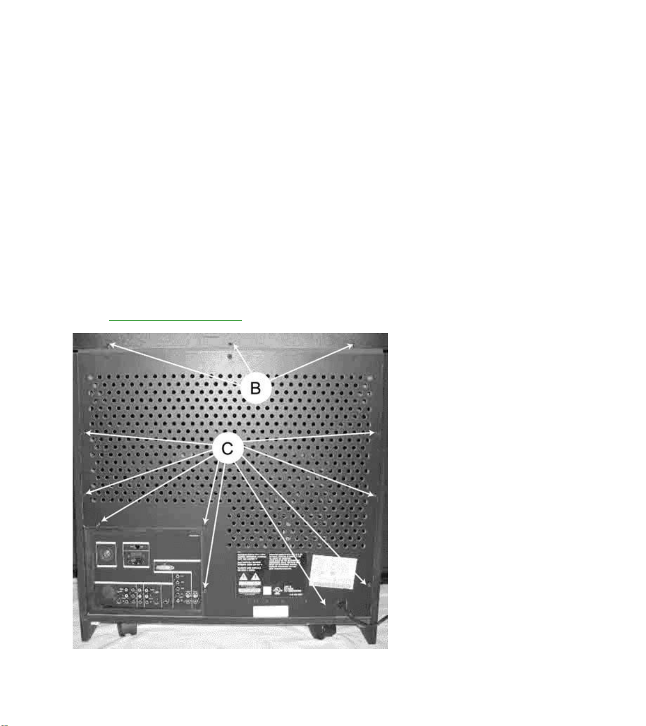
Upper Back Cover (AC02)
1. Remove 12 screws (A).
2. Remove 3 screws (B).
3. Lift cover up to dislodge from pegs (J) and remove cover.
Lower Center Back Cover (AC04)
1. Remove 3 screws (B).
2. Remove 8 screws (C).
Lower Back Cover Removal
Page 11
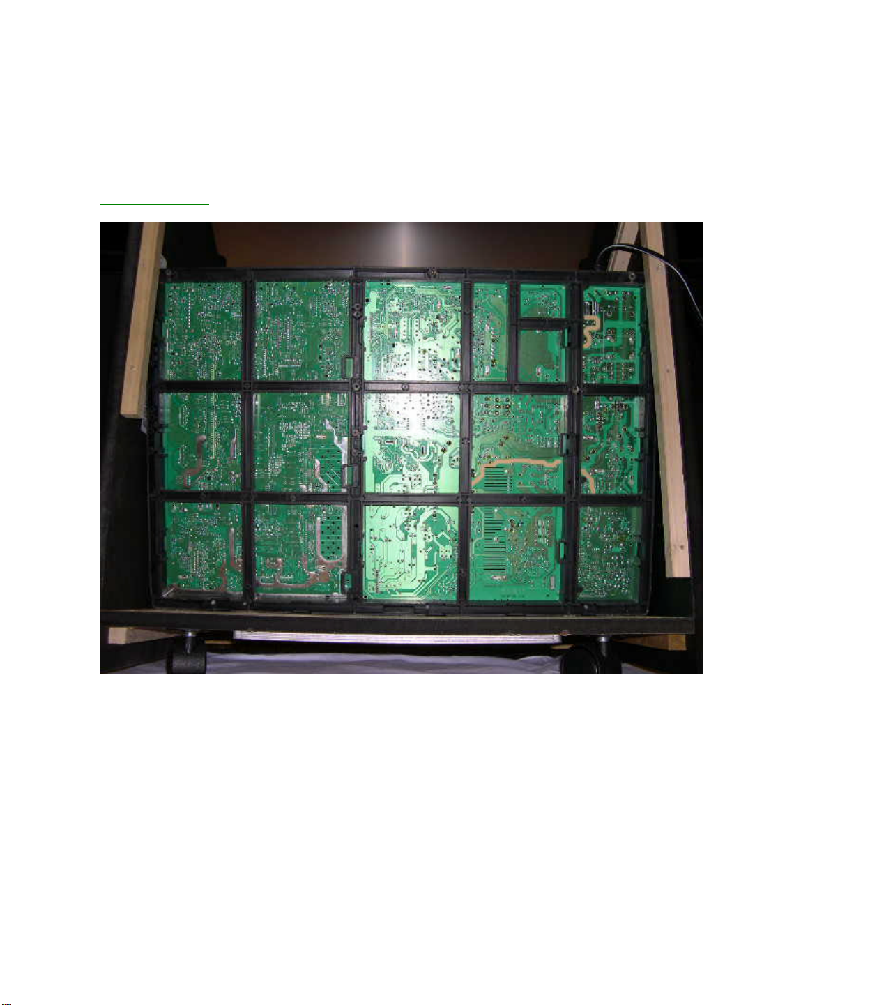
Service Position
(Note: Unplug the AC Line Cord)
This Service Position exposes the entire bottom side of the Power Supply Panel, Large Signal Panel (LSB),
& the Small Signal Panel (SSM). A major portion troubleshooting can be accomplished after completing this
procedure.
Service Position
1. Remove Lower Back Cover.
Remove 12 screws “B & C” required for Lower Back Cover Removal.
2. Loosen the Chassis Frame.
Remove 5 screws “D” that fasten the Chassis Frame to the Cabinet Bottom.
Page 12

Service Pos. Detail - A.
3. Remove Light Barrier (AC07)
Page 13

Service Detail - B
4. Remove 2 screws “E” from the Left Side - Light Barrier Guide and remove this Guide.
5. Grasp the corners of the Chassis Frame and slide in towards you about an inch.
This is required in order that 3 metal cleats (AC36) holding the front edge of the Chassis Frame are
released.
6. While holding the back edge of the Chassis Frame down, grasp the Panel Mounting Bracket (AC21)
and slightly lift the front of the Chassis Frame.
Page 14

Service Detail - C
7. With the rear of the Chassis slightly raised, slide the entire Chassis forward (toward the Cabinet Front),
just far enough that the Rear Jack Panel (AC08) clears the Left Side Mounting Block (for the Lower
Back Cover).
Service Position Detail - D
Page 15

8. Now, lift the back edge of the Chassis Frame (nearest you), up while also lifting (slightly), the front edge
to slide forward in to the Service Position shown.
Service Position Detail - E
Mirror Mounting Board (AC18)
1. Remove 6 screws located in the mirror mounting board brackets and remove the board.
Note: Care should be taken NOT to place fingerprints or smudges on the mirror.
Side Back Covers
1. Remove 4 screws (F) from each of the Side Back Covers. (Some prying may be necessary to dislodge
covers.
Note: This allows access to the Side Jack Panel and Left and Right Speakers.
Large Signal Panel
1. Remove 3 screws from center of the CBA and pull 3 tabs on right of bracket.
2. Lift right side of LSP and slide panel up and out.
Page 16
Power Supply Panel
1. Remove 4 screws from CBA.
2. Lift PFC Filter Panel up and out.
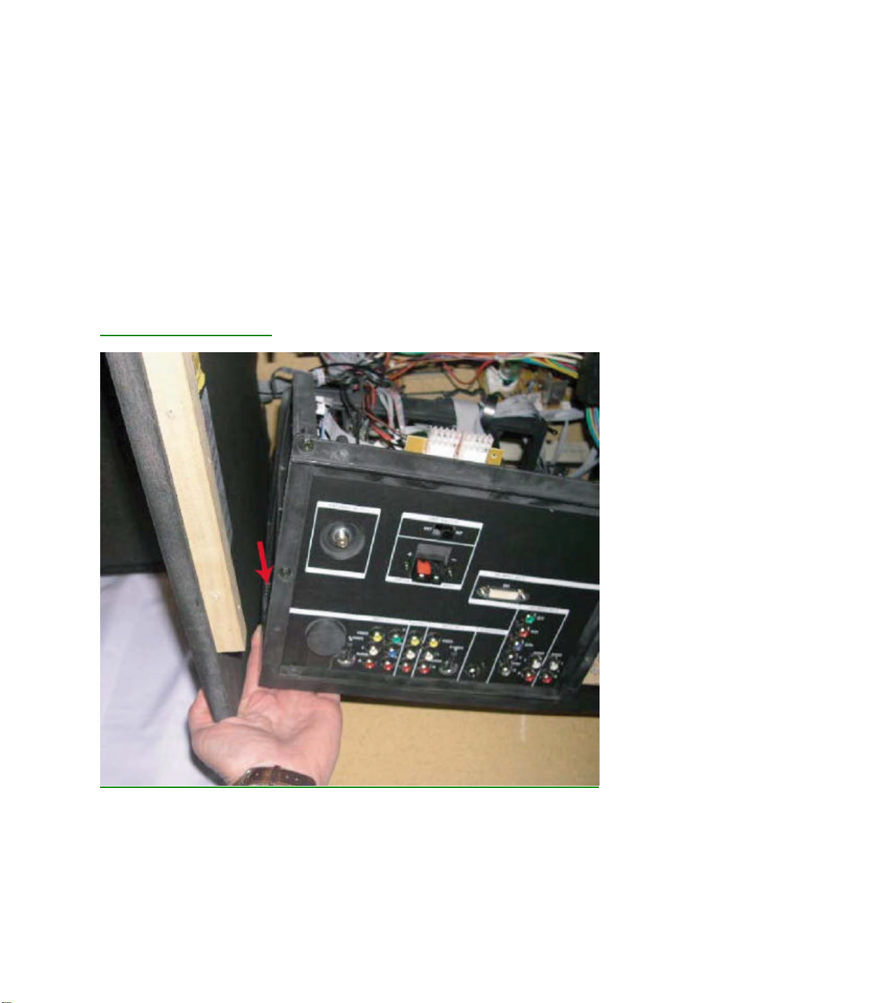
Rear Jack Panel Cover (AC08 & AC27)
1. Complete steps 1 through 7 of the Service Position Procedure (see above). Note: Steps 3 & 4 may be
omitted as removal of the Light Barrier and its Mounting Guide is not required.
2. With the Chassis loose from the cabinet bottom, and the entire chassis repositioned back towards the
Cabinet Front, lift the left end of the Chassis Assembly in order to remove the previously hidden screw
shown in the following detail. Note: This screw may be removed using a ¼ “ nut driver or a T20 Torx
Driver. In either case, an extension may be required in order to achieve the proper angle to the head of
the screw.
Jack Panel Hidden Screw.
3. Remove 2 screws from the left edge and upper left corner of the Rear Jack Panel Cover. These 2
screws may be removed using a ¼ “ nut driver or a T20 Torx Driver and be seen in the following display
on the left edge and upper left corner.
4. Remove the nut around the 75 Ohm Antenna Input
5. Remove 10 more screws shown in the following using a Torx 10 Driver.
Page 17

Jack Panel Screw Removals
6. Disconnect 2 Connectors from the top of the Rear Switch Panel. This Panel fastens to the Jack Panel
Cover and may easily be removed or reconnected once the Jack Panel Cover is completely free of the
Chassis Assembly.
7. Although all screws should now have be removed, care must taken on Core Models featuring the HD
Input. The Jack Panel Cover has a plastic hook that clips in to a hole on the DVI Panel. Gently lift this
hook while removing the Jack Panel Cover.
Jack Panel Hook to DVI Module.
Page 18

Small Signal Panel (SSM)
1. Remove rear Jack Panel cover (AC08).
2. Remove 2 screws from the center of the SSP CBA.
3. Pull 3 tabs on right of panel bracket.
4. Lift right side of SSP, then move to the right to remove.
Side Jack Panel
1. Remove Left Side Back Cover. (See procedure above.)
2. Remove 2 screws from panel.
3. Slide Side Jack Panel CBA out of bracket.
PIP Panel Removal
1. Remove rear Jack Panel cover (AC08).
2. Remove 3 screws from PIP panel.
Small Signal Board (SSB)
1. Remove panel support bracket (AC23).
2. Remove panel support bracket (AC21).
3. Tilt SSB to the right and then up.
Convergence (ACS) Panel Removal
1. Remove panel support bracket (AC21).
2. Release stay tabs on Left side of each board connector and carefully separate ACS from SSP
connectors.
Wide Band Video (HOP) Panel
1. Remove panel support bracket (AC21).
2. Disconnect ribbon cable connectors.
3. Release stay tabs on Left side of each board connector and carefully separate from SSP connectors.
Front Control Panel and Left or Right Speaker
1. Remove front speaker baffle (AC30) by removing Left and Right Side Back Covers.
2. Release 2 tabs on either side of the speaker baffle.
3. Loosen ribbon cable and grounding wire to allow working space.
4. Remove 2 screws to remove Front Control panel.
5. Remove 4 screws each to remove speakers.
Plastic Light Barrier (Optical Assembly)
1. Remove 2 screws (E) located at either end of the plastic light barrier.
Page 19

Complete Optical Assembly or Individual Light Box Assemblies
1. Remove the Plastic Light Barrier.
2. Disconnect the CRT panels, 2nd anode leads (at HVT), and yoke connectors from assemblies to be
removed.
3. To remove the complete Optical Assembly, remove 4 screws (G), and lift assembly
up and out.
4. To remove individual CRT assemblies, remove 4 screws (H), from the assembly
you wish to remove, and lift assembly up and out.
DO NOT disturb the focus assembly wing nuts.
Disassembly Procedures (43 Inch)
All numbers found in the following text refer to the CABINET DISASSEMBLY EXPLODED
VIEW drawing for 43” models.
NOTE: If you are servicing a PCB or speaker, you do not have to remove the plastic upper Back cover.
Lower Back Cover (AC04)
1. Remove 8 screws (A).
2. Remove 4 screws (B).
Upper Back Cover (AC02)
Note: The upper back is a part of the MAIN unit and holds the Mirror.
Removal is only necessary for optical assembly maintenance.
1. Remove 9 screws (C).
2. Perform Lens frame removal procedure.
3. Remove 10 screws (D).
Speaker Baffle (AC30) and Speakers (AC25)
1. Perform Lower Back cover removal procedure. (AC04)
2. Remove 4 screws (E)
3. Carefully pull on Baffle to release guide tabs.
(Note: Unit may have to be tilted backward to remove Baffle.)
4. Remove 4 screws each to remove speakers. (AC25)
Lens Frame Assembly (AC09) and Convergence Sensors
1. Perform Lower Back cover removal procedure. (AC04)
2. Perform Speaker Baffle removal procedure. (AC30)
3. Remove 9 screws (C). (Upper Back)
4. Remove 4 screws (F).
5. Tilt frame forward from top and disconnect cables to Side Jack Panel and Front Control Panel.
Page 20

NOTE: Before performing the next procedure, note the proper location of each of the 4 Convergence
Sensors. (Not in all models.)
6. Snap out the 4 Convergence Sensors and slip connecting wires through slits in the Lens mounting rails.
Note: Be sure to note proper wire routing for later replacement. Wires CANNOT be left so as to
obstruct the mirror reflection.
Front Control Panel
1. Perform Lens Frame removal procedure.
2. Remove 2 screws (G).
Side Jack Panel
1. Perform Lens Frame removal procedure.
2. Remove 2 screws (H)
3. Slide Side Jack Panel CBA out of bracket.
Mirror (AC18) Removal
1. Perform Lens Frame removal procedure.
2. Remove 4 screws located in the mirror mounting brackets and remove the mirror.
Note: Care should be taken NOT to place fingerprints or smudges on the mirror.
Large Signal Panel (LSB)
1. Remove 3 screws from center of the CBA and pull 3 tabs on right of bracket.
2. Lift right side of LSP and slide board up and out.
Power Supply Panel
1. Remove 4 screws from CBA.
2. Lift PFC Filter Panel up and out.
Small Signal Panel (SSM)
1. Remove 2 screws from the center of the CBA.
2. Pull 3 tabs on right of bracket.
3. Lift right side of Small Signal Board up, then to the right to remove.
PIP Panel Removal
1. Remove 3 screws from panel.
Page 21

Removal of SSB Panel
1. Remove panel support clip (AC04).
2. Tilt top of SSB to the right and then up.
Complete Optical Assembly or Individual Light Box Assemblies
1. Perform Lower Back Cover removal procedure.
2. Perform Speaker Baffle removal procedure.
3. Perform Lens Frame removal procedure.
4. Perform Upper Back Cover removal procedure.
5. Disconnect the CRT Panels, 2nd anode leads (at HVT), and yoke connectors from all CRT assemblies.
6. Remove 4 screws located at front of Optical assembly and lift assembly up and out.
7. To remove individual CRT assemblies, loosen 4 screws located in the assembly you wish to remove
and lift assembly up and out.
Service Position
(Note: Side Jack and Front Control Panels may have to be removed to allow cable sl ack.)
1. Perform Back Cover removal procedure.
2. Remove 7 screws (I).
3. Pull Chassis Frame back and up.
4. Tilt Chassis Frame upward on bottom of PTV.
Picture Tube Replacement
Refer to CRT Assembly Exploded View
Replacement of the cathode ray tube (CRT) and/or optical system components of a Projection TV (PTV) can be
easily accomplished by following general guidelines. Use care when working around the CRT and optical
systems of the PTV. The PTV light path encompasses a number of precision optical components. These include
lenses, mirrors, the lenticular screen, and Fresnel lens. The PTV incorporates three separate CRTs,
representing green, red, and blue outputs. Each CRT uses an independent deflection/convergence yoke,
magnetic centering ring, coupler, C-element lens, and output lens (A/B lens). Each tube is mechanically
fastened to a coupler which houses fluid (a glycol-type substance) used to cool the high temperatures
generated by the small (7") CRTs. The fluid also provides an optical characteristic supporting the optical system
of the PTV. When replacement of a CRT or optical component is required, caution must be exercised in
preventing fluid spillage. The technician must carefully reassemble the CRT/optical components, ensuring a
proper seal of the coupling fluid. Use only factory original coupling fluid.
Caution: Do not use or add water as an alternative to the prescribed coupling fluid.
The following procedure should be used when performing repairs on the CRT/optical assemblies of the
Projection TV.
Note: Upon completion of CRT/optical assembly repair, the centering, convergence, gray scale, mechanical
and electrical focus adjustments are required. If more than one assembly requires repair, it is recommended the
service technician fully complete one assembly at a time, using the existing assemblies as a reference for the
alignment of the centering and convergence.
Page 22

A. Single CRT/Lens Assembly from the Light Rack
1a) Remove AC power from the PTV.
2a) Remove the upper and lower back covers (1/4" screws).
3a) Remove the barrier board and the shield cover from around the lens assemblies (1/4" screws).
4a) Carefully remove the CRT Socket Board from the CRT of the CRT/optical assembly being serviced.
5a) Remove the yoke and convergence plugs, of the CRT/optical assembly being serviced, from the Large
Signal Module.
6a) Remove the high voltage anode lead from the HV splitter block on the Large Signal Module of the
CRT/optical assembly being serviced. Remove ground lug connectors from the coupler frame.
7a) Remove the four 1/4" screws that secure the CRT/lens assembly to the light rack. These four screws are
located in each corner, on the top of the coupler assembly.
Caution: Do not remove the bolts with pressure springs or the inverted Torx screws of the CRT/lens assembly.
The removal of these components could result in fluid spillage into the PTV cabinet.
8a) Carefully remove the CRT/lens assembly from the PTV cabinet.
Servicing the CRT/Optical Assembly
Caution: Do not attempt any repairs on the CRT/optical block assembly without first removing the CRT coupling
fluid. Removal of the delta output lens will result in spillage of the coupling fluid.
Caution: Coupling fluid is a poisonous solution containing a high concentration of ethylene glycol. Do not leave
exposed fluid unattended. Prevent children or pets from coming into contact with the fluid. Clean up spills
immediately.
B. Removing the PTV Coupling Fluid
All repairs made to the CRT/optical block assembly require the removal of the coupling fluid. The following
procedure describes how to remove the PTV coupling fluid.
1b) Lay the CRT assembly on its side with the plug pointing up.
2b) Remove the plug (X8).
3b) Remove some of the fluid from the coupler to prevent spillage when the CRT is removed. An empty
coupling fluid bottle with a cone top is recommended to lower the fluid level within the coupler. Squeeze
and hold the bottle and insert the tip of the cap into the drain hole of the coupler. Loosen the grip on the
bottle, allowing the fluid to be pulled up into the bottle. Save the fluid.
4b) Reinstall the plug (X8).
5b) Stand the CRT assembly up with the neck of the CRT pointing up.
6b) With an awl or marking pen, outline the edges of the CRT onto the coupler.
Note: The correct positioning of the CRT to the coupler is critical to the optimum performance of the optical
system.
7b) Remove the four CRT mounting bolts (A) (with springs and spacers) and remove the mounting bracket
(D).
8b) Remove the four CRT mounting ear screws.
Note: The CRT mounting ear screws are not used on some assemblies.
9b) Gently remove any metal shavings from around the screw holes. Do not allow the metal shavings to get
into the fluid.
10b) Note the position of the high voltage anode cap with respect to the coupler.
11b) Carefully remove the CRT from the coupler. Wipe any excess fluid from the faceplate of the CRT. Set the
CRT aside.
12b) Use an empty coupling fluid bottle to extract the remainder of the fluid from the coupler.
Page 23

Note: Complete removal of the coupling fluid is not necessary when only replacing the CRT.
13b) Clean any remaining fluid from the coupler and the CRT gasket channel using absorbent tissue. Refer to
"C". Cleaning the Coupler, C-element Lens and CRT Faceplate procedure if the fluid is discolored or
contaminated.
14b) Make all necessary repairs.
C. Cleaning the Coupler, C-element Lens and CRT Faceplate
1c) Remove CRT coupling fluid as described in steps 1b through 13b.
2c) Using denatured alcohol on a cloth made of 100% cotton or a lens cleaning tissue, gently clean the C-
element (fisheye) lens, coupler and the CRT faceplate. Thoroughly clean the coupler assembly, including
the expansion chamber bladder, and allow to fully dry.
Caution: Do not use soap or detergent type substances to clean the coupler and its related assemblies. Water
can be used as an alternative to denatured alcohol, but the assemblies must be completely dry prior to
reassembly of the coupler and the addition of the coupling fluid. A hair dryer may be used to dry the
coupler and its assemblies prior to reassembly. If contaminated fluid is discovered, the coupler and its
related assemblies must be completely disassembled and cleaned to prevent a reoccurrence.
3c) Replace the CRT and C-element lens gaskets.
4c) Reassemble the C-element lens and the output lens to the coupler.
5c) Refer to "Replacing the CRT Coupling Fluid" upon completion of necessary repairs and cleaning of the
optical/coupler assemblies.
D. Replacement of the CRT
1d) Remove CRT coupling fluid as described in steps 1b through 13b.
2d) Remove the plastic protective coating (if present) from the faceplate of the replacement CRT.
3d) Refer to "Replacing the CRT Coupling Fluid" to complete the CRT replacement.
E. Repair or Replacement of the Optical/Coupler Assembly
1e) Remove CRT coupling fluid as described in steps 1b through 13b.
2e) Remove the four inverted-type Torx screws which secure the Delta output lens to the coupler. An
inverted-type Torx socket can be purchased using part number 483539517303.
3e) Removal of the Delta output lens will allow access to the C-element lens, C-element gasket, coupler, and
its assemblies.
4e) Refer to "Replacing the CRT Coupling Fluid" upon completion of necessary repairs to the optical/coupler
assemblies.
F. Replacing the PTV Coupling Fluid
Note: Prior to replacing the CRT coupling fluid, ensure the expansion chamber bladder is fully collapsed. This
can be easily inspected by viewing the bladder through the small hole on the expansion chamber
assembly. If the rubber of the bladder is not easily visible through the small hole, then the bladder may be
considered collapsed and fluid can be added. If the rubber of the expansion chamber bladder is visible at
the hole of the expansion chamber, then replacement of the expansion chamber bladder is required.
Note: The CRT coupling fluid is critical to the optical performance of the PTV. Use only part number
483531057233 (3 bottle kit) or 483531067004 (1 bottle) to ensure the optical integrity and performance
reliability of the PTV when replacing the CRT coupling fluid.
Page 24

1f) Reinstall the CRT gasket into the gasket channel of the coupler. Confirm the placement of the CRT, C-
element lens, and vent plug gaskets.
2f) Place the CRT onto the coupler with the high voltage anode lead positioned as marked in step 10b of
procedure B.
3f) Carefully position the CRT onto the coupler, using the outline defined in step 6b of procedure B as a
reference.
4f) Start the CRT mounting ear screws but do not tighten them.
5f) Tighten the CRT mounting ear screws in a star pattern (like tightening lug nuts on the wheel of a car).
Make sure the CRT does not shift position from the outline defined in step 6b.
Caution: Do not over tighten the CRT ear screws.
Note: The CRT mounting ear screws are not used on some assemblies.
6f) Install the CRT mounting bracket and start the four CRT mounting bracket bolts with springs.
7f) Tighten the bolts in a star pattern.
8f) Lay the CRT assembly on its side with the plug pointing up.
9f) Remove the plug.
10f) Using the PTV coupling fluid bottle with the cone top, refill the coupler with fluid through the drain access
hole. Completely fill the coupler chamber so the fluid is level with the top of the coupler at the plug. Wipe
any excess fluid from around the coupler.
11f) Reinstall the plug and check for any fluid leaks.
12f) Install the repaired CRT/optical block assembly into the PTV and perform any necessary adjustments.
Page 25

EMG-Star PTV Service Adjustments
Manual 7655
DPTV355 Series Chassis Adjustments
The following topics are covered:
• Service Modes
• Error code buffer and error codes
• The “blinking LED” procedure
• Trouble shooting tips
• Customer Service Mode
Measurements should be performed under the following conditions:
Video: color bar signal
Audio: 3kHz left, 1kHz right
Panel Location Guide
Page 26
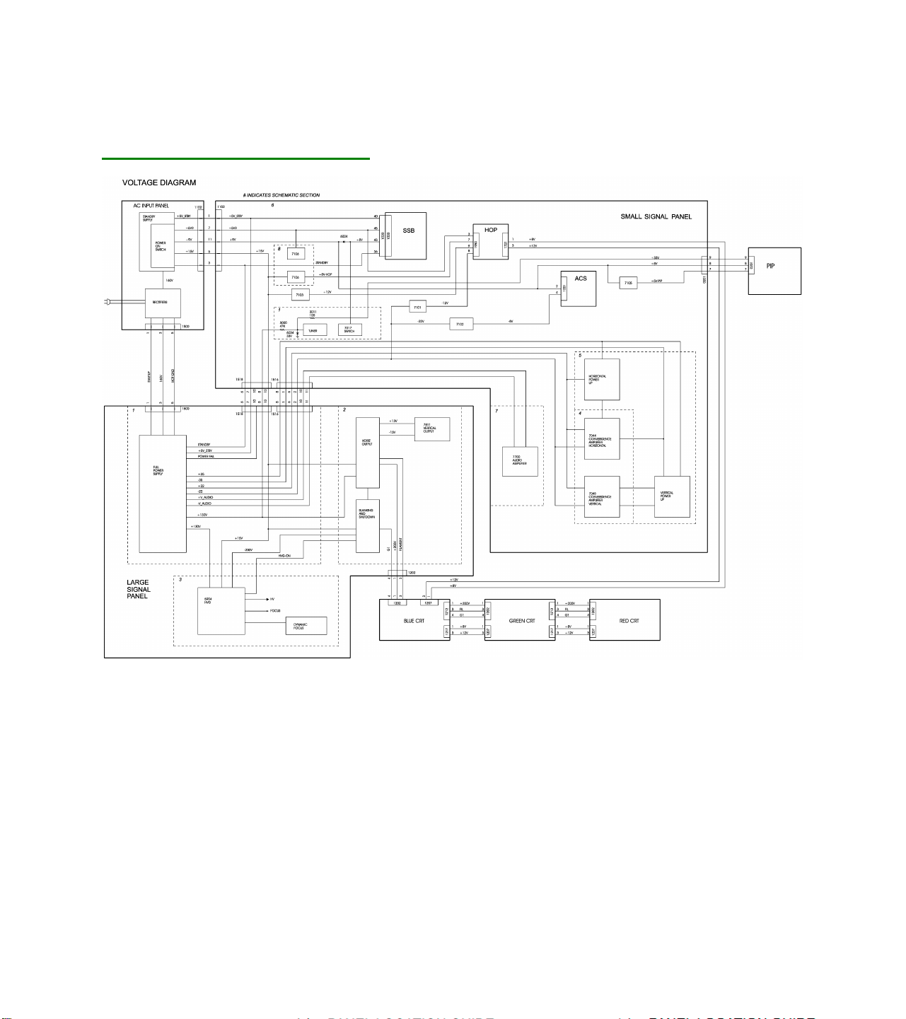
Voltage Checks
DPTV355 Series Voltage Diagram
Service Default Mode (SDM)
Introduction
The Service Default Mode (SDM) is a technical aid for the service technician. The Service Default Mode (SDM)
establishes fixed, repeatable settings of customer controls, which allow consistent measurements to be made.
The SDM also initiates the blinking LED procedure and, if necessary, overrides the 5V protection.
The SDM places the set in the following pre-defined conditions:
• Tuning frequency set to channel 3.
• Volume level set to 25% (of the maximum volume level).
• Other picture and sound settings set to 50% (mid-range).
Page 27

The following functions are turned OFF while in SDM:
• Timer
• Sleep timer
The following functions are disabled during SDM (and enabled after leaving SDM):
• Parental lock
• Blue mute
• Hospitality Mode
• No-ident Timer (normally the set is automatically switched off when no video signal (IDENT) is received for
15 minutes).
All other controls operate normally.
Entering Service Default Mode
To enter the Service Default Mode, press the following key sequence on the remote control transmitter:
0-6-2-5-9-6-MENU
Do not allow the display to time out between entries while keying the sequence.
Upon entry into the Service Default Mode, the letters “SDM” will be displayed at the upper right corner of the
screen. You may exit the SDM by pressing “0, 0” on the remote transmitter.
The screen will display “SDM” in the upper right hand corner of the screen.
The Blinking LED Procedure in the Service Default Mode
The contents of the error buffer can also be made visible through the “blinking LED” procedure. This is
especially useful when there is no picture.
• When the SDM is entered, the LED will blink the number of times equal to the value of the error code.
Error-codes equal to or greater10 are shown in the following manner: A long blink of 750 mSeconds
indicating the decimal digit, followed by a pause of 1500 mSeconds. The LED will then blink the number
equal to the error code. When all error-codes are displayed, the sequence is finished with an LED
display of 3 seconds. At this point the sequence will begin again.
Example:
Error code position 1 2 3 4 5
Error buffer: 12 9 8 0 0
• After entering SDM: The sequence will begin with 1 long blink of 750 mSeconds, then pause 1500
mSeconds, then blink twice (indicating error code 12), then the LED will pause for 3 seconds, then blink
9 times (indicating error code 9), then the LED will pause for 3 seconds, then blink 6 times (indicating
error code 6), then pause 3 seconds and blink for 3 seconds again, ending the blinking sequence.
NOTE: If errors 1, 2, 3, or 4 occur the LED ALWAYS blinks indicating the last error which occurred, even if the
set is NOT in service mode.
Page 28

Exiting Service Default Mode
To exit the Service Default Mode, press the Power button.
Note: To save the error codes, unplug the AC power cord without turning off the set. When the power is
turned back on, the Service Default Mode will still be active.
Service Alignment Mode (SAM)
Introduction
The Service Alignment Mode (SAM) is used to align the set and/or adjust the option settings and to display/clear
the error code buffer values.
Entering Service Alignment Mode
To enter the Service Alignment Mode (SAM), press the following key sequence on the remote control
transmitter:
0 6 2 5 9 6 I +
Do not allow the display to time out between entries while keying the sequence.
Exiting SAM:
To exit the Service Alignment Mode, press the Power button.
Note: To save the error codes, unplug the AC power cord without turning off the set. When the power
is turned back on, the Service Alignment Mode will still be active.
In SAM the following information is displayed on the screen:
SAM Menu
Page 29

Explanation of SAM Menu:
1 Operation Hours (Run Timer):
This display indicates the accumulated total operational hours. (Shown in hexadecimal
format)
2 Software identification of the main micro controller
ROM version: Jun 10 2003 EM5US1-MR5.0_90191
EM5 is the engineering chassis name for the EMG-Star PTV chassis.
• US1 is 2 letter and 1 digit combination to indicate the software type and the supported
languages:
• US = NAFTA
• 1 = Main Software language version number
• 5.0_90191 = sub-version number
3 Error buffer (10 errors possible):
Displays the 5 most recent errors. The most recent error is displayed at the upper left.
4 Option codes (2 Groups shown) (8 codes possible):
Summary of options is explained below.
SAM Menu Control
Menu items may be selected using the cursor UP/DOWN keys.
• the selected item will be highlighted.
• when not all menu items will fit on the screen, pressing the cursor UP/DOWN keys on the remote transmitter
will display the next/previous menu items.
With the cursor LEFT/RIGHT keys, it is possible to:
• activate/deactivate the selected menu item (e.g. GEOMETRY)
• change the value of the selected menu item (e.g. VER-SLOPE )
• activate the selected submenu (e.g. SERV-BLK)
Access to normal user menu
Pressing the “MENU” button on the remote control switches between the SAM and the normal user menus
(with the SAM mode still active in the background). Pressing the “MENU” key in a submenu will return the
screen to the previous menu.
Menu and Sub-menu Definitions
Clear Errors
Erases the contents of the error buffer. Select the CLEAR ERRORS menu item and press the cursor LEFT or
cursor RIGHT key. The contents of the error buffer are cleared.
The functionality of the OPTIONS and ALIGNMENTS (TUNER, WHITE TONE, GEOMETRY, SOUND, and
SMART SETTING) sub-menus are described in the service adjustments.
Page 30

Error code buffer and error codes
Explanation of the Error code buffer
The error code buffer contains all errors detected since the last time the buffer was erased. The buffer is
written from left to right. When an error occurs that is not yet in the error code buffer, the error code will
appear at the left side and all other errors indicators will shift one position to the right.
The error code buffer will be cleared in the following cases:
• by activating CLEAR ERRORS in SAM menu
• exiting SDM or SAM with the “Standby" command on the remote control
• upon automatic reset when content has not changed for 50 consecutive hours
By leaving SDM or SAM via the power switch, the error buffer will not be reset.
Examples:
ERROR: 0 0 0 0 0 0 0 : No errors detected
ERROR: 8 0 0 0 0 0 0 : Error code 8 is the last and only detected error
ERROR: 9 8 0 0 0 0 0 : Error code 8 was first detected and error code 9 is
the last detected (newest) error
The contents of the error buffer can also be displayed by use of the “blinking LED” procedure, if no picture is
available. See explanation of “The blinking LED procedure “below.
Error code definition
In case of non-intermittent faults, clear the error buffer before starting the repair. Make sure “old” error codes
are not present. If possible check the entire content of the error buffers. In some situations an error code is only
the result of another error code (and not the actual cause).
Note: A fault in the protection detection circuitry can also lead to a protection.
Error codes 1,2, 3, and 4 are protection codes, and in this case the supplies of some circuits will be switched off.
Also in protection, the LED will blink the number of times equivalent to the most recent error code.
Page 31

Error Code Table
Error
Code
1* M24C32 NVM 1
2 Hfail Protection HFB Protection 18
3 SAA4978 Picnic 4
4 Supply 5V 5V Protection 15
5
6 ** Slow I2c bus blocked 13
8 TDA9320 HIP I/O-video processing 8
9 PCF8574 Wireless Expander 23
10 Will not be used due to
12 TDA9178 Topic (LTP Peaking) 3
13 UV1316/TEDE9 Tuner Protection 7
14 MSP3411/3412/3452 ITT Sound Processor 6
15 UPD64083 3D Comb Filter Protection 3
16 FBX Feature Box Protection 24
17 M62320P I/O Expander HD Interface 34
18 Fast I2c bus blocked 14
19 TDA8444 Auto Scavem DAC 35
21 M32.20P PIP I/O Expander 11
22 TDA888X PIP BOCMA 11
23 TELE9 PIP Tuner 11
24 SAAB9081 PIP Muppet 11
25 Z86130 PIP V-Chip 11
26 SAA4992 Falconic 24
27 Eagle Eagle Device 24
28 Back Current Loop Back Current Loop 3
32 Flash Ram (EPG) Flash Ram (EPG) 38
Device Description Module Number
Supply 8V
difficulty in recognizing
this code using the
Blinking LED procedure.
8V Protection 16
Option Codes
Option codes for each model are located on the label on the back cover of the set.
Page 32

Option Code Table
SAM Option Codes
Alignments
General
Option Default
Luma Gain 3 0-3
IF AFC 0-127
IF Lprime AFC 80 0-127
Tuner AGC 0-63
Tuner AGC (Tuner 2) 0-63
Blend Intensity 16 0-31
Luminance Delay Default
Pal BG 11 0-11
Pal I 8 0-11
Secam 8 0-11
Bypass 9 0-11
Dealer Options
Personal Options Default
Picture Mute no (no/yes)
Virgin Mode no (no/yes)
Service Options
Video Repro Default
Light Senso yes (no/yes)
3D Combfilter yes (no/yes)
Pixel Plus yes (no/yes)
Miscellaneous Default
Tuner Type TEDE9 (TEDE9 / UV1316)
Range
Range
Range
Range
Range
Page 33

ELECTRICAL FOCUS ADJUSTMENT
Note: Before beginning the following adjustment procedures set the customer picture, sharpness, brightness,
and tint controls to midrange and the customer color control to minimum.
Electrical Focus Adjustment
1. Remove the back cover of the set and the light shield, then turn the set on and inject an NTSC
crosshatch pattern signal into the antenna terminal.
Note: The crosshatch pattern will appear clearer if the front of the screen is covered with a dark cloth.
2. Cover two of the CRT output lenses with cardboard pieces (or other non-conductive opaque material) to
observe the magnified reflection of the other picture tube on the back side of the viewing screen.
3. Adjust the CRT’s focus control (located on the Screen/Focus Control Block) for the sharpest raster
image.
4. Confirm correct focus by viewing the screen from the front of the set.
5. Repeat steps two through four to adjust the focus of the two remaining CRT’s.
Note: Before beginning the following adjustment procedures, set the customer picture, sharpness, brightness,
and tint controls to midrange and the customer color control to minimum.
OPTICAL FOCUS
1. Remove the back cover of the set and the light shield, then turn these on and inject an NTSC
crosshatch pattern signal into the antenna terminal.
Note: The crosshatch pattern will appear clearer if the front of the screen is covered with a dark cloth.
2. Cover two of the CRT output lenses with cardboard pieces (or other non-conductive, opaque material)
and observe the magnified reflection of the other picture tube on the back side of the viewing screen.
3. Loosen the lens retaining wing nuts on the CRT Focus Assembly.
4. Move the wing nut in the slot of the uncovered lens to locate the optimum optical focus (viewing the
picture from the back side of the screen), then re-tighten the wing nut.
5. Confirm correct focus by viewing the screen from the front of the set.
6. Repeat steps two through five to adjust the focus of the two remaining CRT’s.
Picture Tube Replacement
Replacement of the cathode ray tube (CRT) and/or optical system components of a Projection TV (PTV) can be
easily accomplished by following general guidelines. Use care when working around the CRT and optical
systems of the PTV. The PTV light path encompasses a number of precision optical components. These include
lenses, mirrors, the lenticular screen, and Fresnel lens. The PTV incorporates three separate CRTs,
representing green, red, and blue outputs. Each CRT uses an independent deflection/convergence yoke,
magnetic centering ring, coupler, C-element lens, and output lens (A/B lens). Each tube is mechanically
fastened to a coupler which houses fluid (a glycol-type substance) used to cool the high temperatures
generated by the small (7") CRTs. The fluid also provides an optical characteristic supporting the optical system
of the PTV. When replacement of a CRT or optical component is required, caution must be exercised in
preventing fluid spillage. The technician must carefully reassemble the CRT/optical components, ensuring a
proper seal of the coupling fluid. Use only factory original coupling fluid.
Caution: Do not use or add water as an alternative to the prescribed coupling fluid.
Page 34

The following procedure should be used when performing repairs on the CRT/optical assemblies of the
Projection TV.
Note: Upon completion of CRT/optical assembly repair, the centering, convergence, gray scale, mechanical
and electrical focus adjustments are required. If more than one assembly requires repair, it is
recommended the service technician fully complete one assembly at a time, using the existing
assemblies as a reference for the alignment of the centering and convergence.
Disassembly Procedures
A. Removal of a single CRT/Lens Assembly from the light rack
1a) Remove AC power from the PTV.
2a) Remove the upper and lower back covers (1/4" screws).
3a) Remove the barrier board and the shield cover from around the lens assemblies (1/4" screws).
4a) Carefully remove the CRT Socket Board from the CRT of the CRT/optical assembly being serviced.
5a) Remove the yoke and convergence plugs, of the CRT/optical assembly being serviced, from the
Large Signal Module.
6a) Remove the high voltage anode lead from the HV splitter block on the Large Signal Module of the
CRT/optical assembly being serviced. Remove ground lug connectors from the coupler frame.
7a) Remove the four 1/4" screws that secure the CRT/lens assembly to the light rack. These four screws
are located in each corner, on the top of the coupler assembly.
Caution: Do not remove the bolts with pressure springs or the inverted Torx screws of the
CRT/lens assembly. The removal of these components could result in fluid spillage into the
PTV cabinet.
8a) Carefully remove the CRT/lens assembly from the PTV cabinet.
Servicing the CRT/Optical Assembly
Caution: Do not attempt any repairs on the CRT/optical block assembly without first removing the CRT
coupling fluid. Removal of the delta output lens will result in spillage of the coupling fluid.
Caution: Coupling fluid is a poisonous solution containing a high concentration of ethylene glycol. Do
not leave exposed fluid unattended. Prevent children or pets from coming into contact with the fluid.
Clean up spills immediately.
B. Removing the PTV Coupling Fluid
All repairs made to the CRT/optical block assembly require the removal of the coupling fluid. The following
procedure describes how to remove the PTV coupling fluid.
1b) Lay the CRT assembly on its side with the plug pointing up.
2b) Remove the plug (X8).
3b) Remove some of the fluid from the coupler to prevent spillage when the CRT is removed. An empty
coupling fluid bottle with a cone top is recommended to lower the fluid level within the coupler.
Squeeze and hold the bottle and insert the tip of the cap into the drain hole of the coupler. Loosen the
grip on the bottle, allowing the fluid to be pulled up into the bottle. Save the fluid.
Page 35

4b) Reinstall the plug (X8).
5b) Stand the CRT assembly up with the neck of the CRT pointing up.
6b) With an awl or marking pen, outline the edges of the CRT onto the coupler.
Note: The correct positioning of the CRT to the coupler is critical to the optimum performance of the
optical system.
7b) Remove the four CRT mounting bolts (A) (with springs and spacers) and remove the mounting
bracket (D).
8b) Remove the four CRT mounting ear screws.
Note: The CRT mounting ear screws are not used on some assemblies.
9b) Gently remove any metal shavings from around the screw holes. Do not allow the metal shavings to
get into the fluid.
10b) Note the position of the high voltage anode cap with respect to the coupler.
11b) Carefully remove the CRT from the coupler. Wipe any excess fluid from the faceplate of the CRT. Set
the CRT aside.
12b) Use an empty coupling fluid bottle to extract the remainder of the fluid from the coupler.
Note: Complete removal of the coupling fluid is not necessary when only replacing the CRT.
13b) Clean any remaining fluid from the coupler and the CRT gasket channel using absorbent tissue. Refer
to "C”. Cleaning the Coupler, C-element Lens and CRT Faceplate procedure if the fluid is discolored
or contaminated.
14b) Make all necessary repairs.
C. Cleaning the Coupler, C-element Lens and CRT Faceplate
1c) Remove CRT coupling fluid as described in steps 1b through 13b.
2c) Using denatured alcohol on a cloth made of 100% cotton or a lens cleaning tissue, gently clean the C-
element (fisheye) lens, coupler and the CRT faceplate. Thoroughly clean the coupler assembly,
including the expansion chamber bladder, and allow to fully dry.
Caution: Do not use soap or detergent type substances to clean the coupler and its related
assemblies. Water can be used as an alternative to denatured alcohol, but the assemblies must be
completely dry prior to reassembly of the coupler and the addition of the coupling fluid. A hair dryer
may be used to dry the coupler and its assemblies prior to reassembly. If contaminated fluid is
discovered, the coupler and its related assemblies must be completely disassembled and cleaned to
prevent a reoccurrence.
3c) Replace the CRT and C-element lens gaskets.
4c) Reassemble the C-element lens and the output lens to the coupler.
5c) Refer to "Replacing the CRT Coupling Fluid" upon completion of necessary repairs and cleaning of
the optical/coupler assemblies.
D. Replacement of the CRT
1d) Remove CRT coupling fluid as described in steps 1b through 13b.
2d) Remove the plastic protective coating (if present) from the faceplate of the replacement CRT.
3d) Refer to "Replacing the CRT Coupling Fluid" to complete the CRT replacement.
E. Repair or Replacement of the Optical/Coupler Assembly
1e) Remove CRT coupling fluid as described in steps 1b through 13b.
Page 36

2e) Remove the four inverted-type Torx screws which secure the Delta output lens to the coupler. An
inverted-type Torx socket can be purchased using part number 483539517303.
3e) Removal of the Delta output lens will allow access to the C-element lens, C-element gasket, coupler,
and its assemblies.
4e) Refer to "Replacing the CRT Coupling Fluid" upon completion of necessary repairs to the
optical/coupler assemblies.
F. Replacing the PTV Coupling Fluid
Note: Prior to replacing the CRT coupling fluid, ensure the expansion chamber bladder is fully collapsed.
This can be easily inspected by viewing the bladder through the small hole on the expansion
chamber assembly. If the rubber of the bladder is not easily visible through the small hole, then the
bladder may be considered collapsed and fluid can be added. If the rubber of the expansion
chamber bladder is visible at the hole of the expansion chamber, then replacement of the expansion
chamber bladder is required.
Note: The CRT coupling fluid is critical to the optical performance of the PTV. Use only part number
483531057233 (3 bottle kit) or 483531067004 (1 bottle) to ensure the optical integrity and
performance reliability of the PTV when replacing the CRT coupling fluid.
1f) Reinstall the CRT gasket into the gasket channel of the coupler. Confirm the placement of the CRT,
C-element lens, and vent plug gaskets.
2f) Place the CRT onto the coupler with the high voltage anode lead positioned as marked in step 10b of
procedure B.
3f) Carefully position the CRT onto the coupler, using the outline defined in step 6b of procedure B as a
reference.
4f) Start the CRT mounting ear screws but do not tighten them.
5f) Tighten the CRT mounting ear screws in a star pattern (like tightening lug nuts on the wheel of a car).
Make sure the CRT does not shift position from the outline defined in step 6b.
Caution: Do not over tighten the CRT ear screws.
Note: The CRT mounting ear screws are not used on some assemblies.
6f) Install the CRT mounting bracket and start the four CRT mounting bracket bolts with springs.
7f) Tighten the bolts in a star pattern.
8f) Lay the CRT assembly on its side with the plug pointing up.
9f) Remove the plug.
10f) Using the PTV coupling fluid bottle with the cone top, refill the coupler with fluid through the drain
access hole. Completely fill the coupler chamber so the fluid is level with the top of the coupler at the
plug. Wipe any excess fluid from around the coupler.
11f) Reinstall the plug and check for any fluid leaks.
12f) Install the repaired CRT/optical block assembly into the PTV and perform any necessary adjustments.
Page 37

Convergence and Geometry adjustments
All of the displays are generated by the OTC, located on the SSB, except the GDE SAM Menu, which is
generated by the Microprocessor located on the ACS Module. All of the settings except the GDE are stored in
the NVM located on the SSB. The Geometry, White Tone, and Convergence settings are stored on the NVM
located on the ACS Module.
The GDE stores the settings for Geometry and White Tone. There is one setting stored for all modes in the GDE
NVM. There are eight different alignment modes for Geometry and Convergence, which are stored in the GDE
NVM. A chart of the Alignment modes is shown below.
Mode Line Frequency Frame Frequency
480p (NTSC Progressive) 31500 60Hz
1080i 33750 60Hz
It is important when adjusting Geometry or Convergence that the correct signal for that mode be applied to the
set.
Any time the Geometry is adjusted, the Convergence should also be adjusted. Failure to do so will result in an
out of Convergence set when the customer uses the Intellisense feature.
Geometry Alignment
Completely read the Setup section before proceeding with any adjustment. The set should be allowed to warm
up for at least 20 minutes before any adjustments are made.
If the ACS module has been replaced, the following adjustments will be required in the order as shown:
Geometry
Convergence
Grey Scale (White Tone)
If the Large Signal Board (LSB) has been changed the following adjustment are required:
Geometry
Convergence
If the CRTs have been changed:
Geometry
Convergence
Grey Scale (White Tone)
If the SSM (Small Signal Module has been changed:
Convergence
Page 38

The Geometry settings are located in the GDE SAM menu. Enter the Service Alignment Mode (SAM) by
entering 0 6 2 5 9 6 I+ on the remote. Cursor down to the Alignments and then Cursor right to locate the GDE
SAM. Press the ok button to enter the GDE SAM mode.
Screen Centering
After replacing the CRTs, it will be necessary to perform Screen Centering. Place the Convergence Template on
the TV screen or place a string from corner to corner to determine the screen center. Apply a center cross
pattern to the TV. Enter the SAM mode, described in the Geometry section and disable Convergence. Cover the
Red and Blue CRTs. Using the Centering rings on the Green CRT, center the cross onto the center of the
template. Uncover the Red CRT and center the Red onto the Green cross. Follow the same procedure with the
Blue CRT. Only perform the Screen Centering for the first mode to be adjusted. Do NOT repeat the adjustment
for the other modes.
Geometry Alignment
The Geometry alignment data is stored in the NVM located on the ACS module. Whenever the ACS module or
the Large Signal Board (LSB) have been changed, a Geometry alignment will be necessary. The Geometry
Alignment is performed in the SAM/GDE alignment mode. Make sure the set is in the mode in which you wish to
align before entering the SAM mode. Use the AV button on the Remote to select the input with a signal applied
after entering the SAM mode.
Apply a crosshatch pattern to the set. Cursor Down to CONV PROC in the menu and press the Right Cursor
button to select. This will disable the Convergence drive. Select Geometry in the menu and enter the following
default values for the mode being adjusted. Other mode values can be entered by selecting a different DISPLAY
MODE in the menu.
The following new screen models are introduced using the EMG-Star High chassis for 2003.
Model Number Aspect ratio Template
55PP9753/17 16x9 ST4181
55PP9753/84 16x9 ST4181
60PP9753/17 16x9 ST4182
Refer to the SAM menu illustration in the SAM section
Page 39

Geometry Default Values
GDE SAM MODE DEFAULTS TABLES
Display Mode 480p 1080i
Wide blank 7 7
Horizontal Shift 25 21
Horizontal Para 38 8
E-W Width 31 44
E-W Para 38 38
E-W Trap 26 26
Horizontal Bow 7 7
Vertical Slope 36 36
Vertical Amp 35 36
S Correction 31 31
Vertical Shift 31 31
Fast Blank 0 1
To exit the Service Alignment Mode (SAM), press “0, 0” on the remote transmitter. Then turn the set Off.
Convergence Alignment
The DPTV300 series PTV incorporates a Digital Convergence system using 208 adjustment points. The
Convergence Processor is located on the ACS (Automatic Convergence System) module. The Convergence
drive circuits are located on the SSM (Small Signal Module). Data for the Convergence and Geometry settings
are stored in the EEPROM located on the ACS module. If the CRTs, the Large Signal Panel (LSP), or the Small
Signal Module (SSM) are changed, a complete Geometry and Convergence alignment will be necessary. If the
ACS module, the Small Signal Panel (SSP), or CRTs are changed, a complete Convergence alignment will be
necessary. To obtain the correct Geometry during Convergence, a template must be used. There are two
Geometry and Convergence settings stored in the EEPROM on the ACS Module for sets with a 16x9 aspect
ratio.
Page 40

Convergence Alignment Guide
Use the Cursor Up-Down button to highlight the selection. Press the Cursor Right button to make the selection.
In the second menu, MANUAL CONVERGENCE WO VIDEO means that the screen behind the adjustment grid
will be blank. MANUAL CONVERGENCE W VIDEO displays the applied video behind the adjustment grid.
RESTORE FACTORY loads the values from the last saved convergence alignment. RESTORE DEFAULT
loads values from the ROM on the ACS Microprocessor. If the ACS module has been changed, there may not
be data in the NVM for RESTORE FACTORY. The RESTORE DEFAULT settings will then be loaded. Loading
default values will overwrite all of the Convergence modes.
A internally generated grid will be displayed in the Convergence mode as shown below. The shaded area is the
screen area. Horizontal lines A and M are displayed on the top and bottom edge of the visible screen area.
Lines 1 and 15 are also displayed on the left and right edge of the visible screen area. Vertical line 0 is
adjustable, but not visible.
Page 41

Touch Up Convergence
When making minor Convergence corrections, move the Cursor to the location to be adjusted then press the
Menu button to adjust that location. When in the adjustment mode, press the Menu button a second time if it is
desired to change the step size of the adjustment. When making minor Convergence corrections, you may
adjust the following:
RED TO GREEN
BLUE TO GREEN
SP RED
MP RED
SP BLUE
MP BLUE
Do not make changes to the Green Geometry without placing a Template over the screen.
Page 42

Green Geometry
The Green Geometry must be done first when performing a complete convergence alignment. A Screen
Template is necessary to obtain the correct geometry. Failure to use the Screen Template or misalignment of
the convergence will result in reduced life of the Convergence amplifiers.
Place the Screen template on the TV screen. Select GREEN in the selection menu. The Cursor will appear in
the center of the screen as shown below.
When the ACS module has been replaced and Default settings have been loaded, the following procedure
should be used to adjust the convergence. Otherwise use the Cursor Up-Down and Right-Left buttons to
Navigate to the area to be adjusted. Press the Menu button to adjust then use the Cursor buttons to move the
Green cross onto the Template. The adjustment of the cross has two step sizes, large and small. Press the
Menu button to toggle between the two. After a point has been adjusted, press the Index button to return to
Navigate. When Default settings have been loaded, the leftmost line that is not visible should be adjusted first.
Adjust the Vertical line 0 while observing line 1 to make line 1 parallel with the left edge of the screen. The
adjustment should only be made in small steps. Do not adjust any one point more than 1/4 the distance of one
grid. After the left most line is adjusted, start at the center left of the screen and work to the right, aligning the
Horizontal line. When adjusting the Horizontal lines, best results are obtained when working from left to right.
After the Center line is adjusted, go to the next line down until all of the lines have been adjusted. Then work
from the center up to adjust the Horizontal lines. Using the same method, work from center out to adjust the
Vertical lines. At least three passes will be necessary to complete the alignment. Press the Index button to
return to the selection menu.
When the Green geometry is complete, Store the data. Remove the Template from the screen. Select Red to
Green in the selection menu. Using the same method that was used to adjust the Green Grid to the Template,
adjust the Red Grid onto the Green Grid. If the set is a later production, select SP RED to center the Red grid
onto the Green grid. Exit this mode by pressing the Menu button. Then select the MP RED to adjust the Red
onto the Green using the 35-point adjustment. When this is complete, select the RED TO GREEN to perform
the 208-point adjustment.
Page 43

When the RED TO GREEN is complete, select the BLUE TO GREEN using the same alignment method as the
RED TO GREEN.
Select STORE to save your the alignments after adjusting each color. Each time data is stored; the Intellisense
circuit will recalculate the position of the four sensors in the set. Exiting the Convergence Mode without saving
will cause the alignments to be lost.
Repeat the adjustment for each of the remaining modes.
Gray Scale Alignment
1. Place the input to the RGB (Aux 5) or Y Pb Pr (Aux 4) mode. Connect a Computer or Computer monitor
generator to the Aux 5 input or a Component Generator to Aux 4.
2. Preset the G2 controls counterclockwise.
3. Turn the Green G2 clockwise to make the menu visible.
4. Enter the SAM mode by entering 0, 6, 2, 5, 9, 6, Index on the Remote Control. Select the GDE mode and
select WHITE TONE.
5. Preset the following registers: Use the Cursor Right-Left buttons to set the value. Use the Cursor Up-Down
buttons to select the register. Press the Menu button to return to exit the WHITE TONE menu.
Name Value
Red Cutoff 3F
Green Cutoff 3F
Blue Cutoff 3F
Red Drive 3F
Green Drive 3F
Blue Drive 3F
6. Set the Brightness, Picture, and Sharpness to their midpoint position. Select a Black Raster pattern on the
computer or computer monitor generator.
7. Place a Scope set to measure DC on each cathode to determine the dominant (lowest) color.
8. Adjust the SUB BRIGHTNESS control to set the Black Level equal to 180 volts on the scope.
9. Move the probe to the remaining cathodes and adjust the corresponding cutoff registers to make the black
part of the waveform at 180 volts.
10. Set the corresponding G2 control to just make cutoff for the black part of the waveform for that tube.
11. Remove the Scope.
12. Apply a Grayscale pattern to the set.
13. Adjust the Drive Controls to achieve the proper white balance. At least one drive should remain 3F.
14. The following Drives and Cutoffs should be set as listed. These are in the WHITE TONE menu.
Cool Cutoff Red 0
Cool Cutoff Green 0
Cool Cutoff Blue 0
Cool Drive Red -7
Cool Drive Green -6
Cool Drive Blue 0
Warm Cutoff Red 0
Warm Cutoff Green 0
Page 44

Warm Cutoff Blue 0
Warm Drive Red +7
Warm Drive Green +4
Warm Drive Blue -6
15. Press the Menu button to return to the SAM menu. Exit the Service mode by turning the set Off.
See the GDE SAM mode display in the SAM menu
SAM Menu
The Geometry alignments are in the GDE SAM selection. Use the cursor up-down button to highlight the item.
Use the right cursor button to select the item. Use the Menu button to return to the previous menu. The
following menu will appear when GDE SAM is selected.
Page 45

GDE SAM Screen Display
In this menu, the Display Mode can be selected. If the input signal is NTSC, the selection should be 480P. The
selection Serv Blank causes the bottom half of the screen to blank. This selection is useful when adjusting the
Yoke rotation. The Conv Proc selection allows for the disabling of the Convergence drive.
Default settings should be entered when the Small Signal Board (SSB) has been changed. When the CRTs
have been changed, the display should be centered using the Centering rings on the CRT. The center point
can be found by placing a string from corner to corner or by using the center point on the Convergence
Template. In the 4x3 Aspect ratio sets, there are three Geometry settings. In the 16x9 Aspect ratio sets, there
are two Geometry settings. Make sure the set is in the mode that is being adjusted and that the correct signal is
applied.
Page 46

DPTV335(7655)
Page 47

DPTV335(7655)
Page 48

DPTV335(7655)
Page 49

DPTV335(7655)
Page 50

DPTV335(7655)
Page 51

DPTV335(7655)
Page 52

DPTV335(7655)
Page 53

DPTV335(7655)
Page 54

DPTV335(7655)
Page 55

DPTV335(7655)
Page 56

DPTV335(7655)
Page 57

DPTV335(7655)
Page 58

All Models (7655) - Interconnect Wiring Diagram
Page 59

All Models (7655) - Power Supply Panel Schematic
Page 60

All Models (7655) - LSB Panel (1 of 3)
Page 61

All Models (7655) - LSB Panel (2 of 3)
Page 62

All Models (7655) - LSB Panel (3 of 3)
Page 63

All Models (7655) - SSM Panel (1 of 8)
Page 64

All Models (7655) - SSM Panel (2 of 8)
Page 65

All Models (7655) - SSM Panel (3 of 8)
Page 66

All Models (7655) - SSM Panel (4 of 8)
Page 67

All Models (7655) - SSM Panel (5 of 8)
Page 68

All Models (7655) - SSM Panel (6 of 8)
Page 69

All Models (7655) - SSM Panel (7 of 8)
Page 70

All Models (7655) - SSM Panel (8 of 8)
Page 71

All Models (7655) - Red CRT Panel
Page 72

All Models (7655) - Green CRT Panel
Page 73

All Models (7655) - Blue CRT Panel
Page 74

All Models (7655) - Auto Convergence Panel (1 of 3)
Page 75

All Models (7655) - Auto Convergence Panel (2 of 3)
Page 76

All Models (7655) - Auto Convergence Panel (3 of 3)
Page 77

All Models (7655) - Solar Cell Panel
Page 78

All Models (7655) - Side Jack Panel
Page 79

All Models (7655) - Keyboard Panel
Page 80

All Models (7655) - HOP Panel (1 of 2)
Page 81

All Models (7655) - HOP Panel (2 of 2)
Page 82

All Models (7655) - 3D Comb Filter Panel
Page 83

All Models (7655) - Rear Switch Panel
Page 84

All Models (7655) - SSB Module, B1 (1 of 10)
Page 85

All Models (7655) - SSB Module, B2 (2 of 10)
Page 86

All Models (7655) - SSB Module, B3A (3 of 10)
Page 87

All Models (7655) - SSB Module, B3B (4 of 10)
Page 88

All Models (7655) - SSB Module, B3C (5 of 10)
Page 89

All Models (7655) - SSB Module, B4 (6 of 10)
Page 90

All Models (7655) - SSB Module, B5 (7 of 10)
Page 91

All Models (7655) - SSB Module, B6 (8 of 10)
Page 92

All Models (7655) - SSB Module, B9 (9 of 10)
Page 93

All Models (7655) - SSB Module, B10 (10 of 10)
Page 94

All Models (7655) - DW PIP Panel, F1 (1 of 6)
Page 95

All Models (7655) - DW PIP Panel, F2 (2 of 6)
Page 96

All Models (7655) - DW PIP Panel, F3 (3 of 6)
Page 97

All Models (7655) - DW PIP Panel, F4 (4 of 6)
Page 98

All Models (7655) - DW PIP Panel, F5 (5 of 6)
Page 99

All Models (7655) - DW PIP Panel, F6 (6 of 6)
Page 100

All Models (7655) - DVI Interface Panel
 Loading...