

Philips DC-570 Service Manual

Docking Entertainment System
DC570/12/37/98
TABLE OF CONTENTS
Page
PCBs Location & Version Variations .....................................1-2
Specifi cations .......................................................................1-3
Measurement Setup .............................................................1-4
Service Aids, Service Instruction, etc ...................................1-5
Software Version Checking .....................................................2
Set Block Diagram ...................................................................3
Set Wiring Diagram .................................................................4
MCU & USB Board .................................................................. 5
Key & LCD Board ....................................................................6
Power Amp Board.................................................................... 7
Rectifi er Board .........................................................................8
IPOD Jack & USB Jack & AUX Board .....................................9
Set Mechanical Exploded View & Parts List ..........................10
Revision List ...........................................................................11
©
Copyright 2009 Philips Consumer Electronics B.V. Eindhoven, The Netherlands
All rights reserved. No part of this publication may be reproduced, stored in a retrieval system or
transmitted, in any form or by any means, electronic, mechanical, photocopying, or otherwise without
the prior permission of Philips.
Published by SL 0934 Service Audio Printed in The Netherlands Subject to modification
Version 1.4
CLASS 1
LASER PRODUCT
3141 785 32834

PCBS LOCATION
IPOD JACK BOARD
MCU & USB BOARD
KEY & LCD BOARD
USB JACK BOARD
AUX BOARD
TUNER MODULE
POWER AMP BOARD
1 - 2
VERSION VARIATIONS
Board in used:
MCU & USB BOARD
KEY & LCD BOARD
USB JACK BOARD
POWER AMP BOARD
RECTIFIER BOARD
TUNER MODULE
IPOD & USB JACK BOARD
Features
in used:
Line Out
Video Out
Subwoofer Out
Digital Out
Karaoke Features
Voltage Selector
ECO Power Standby (LCD Display Off)
USB Direct
Type /Versions:
Service policy
/05 /12 /55 89/16/85/
C
C
C
C
C
M
C
Type /Versions:
Feature diffrence
/05
/12 /37
xniRDC/nixuA
x
RECTIFIER BOARD
DC570
/37
C
C
C
C
C
M
C
C
C
C
C
C
M
C
DC570
89/
x
x
x
x
x
x
x
x
x
x
* TIPS : C -- Component Lever Repair.
M -- Module Lever Repair
-- Used
x
Remark: version /37 only for Latam.
for Nafta, service policy should be OCX.

SPECIFICATIONS
1 - 3
AMPLIFIER
Output power ........................................................................
...................................................................... 50W+2 x 25W
Signal-to-noise ratio ....................................... t 70 dBA
Frequency response ...... 50 Hz – 20 KHz, ± 3 dB
Input sensitivity AUX ....................... 0.5 V (max. 2 V)
SUBWOOFER
Frequency response ............................ 50 Hz – 1KHz
Impedance ........................................................................ 8 :
Rated power ................................................................ 50W
TWEETER
Frequency response ..................... 160 Hz – 16 KHz
Impedance ........................................................................ 4 :
Rated power ........................................................ 2 x 25W
TUNER
FM wave range ................................... 87.5 – 108 MHz
Sensitivity at 75 :
– FM ................................................................................ 20dBf
Total harmonic distor tion ..................................... d 1%
Frequency response
– FM .............................................................. 63 – 6000 Hz
Signal-to-noise-ratio
– FM ....................................................................... t 50 dBA
USB PLAYER
USB ................................................................... 12Mb/s, V1.1
......................................... support MP3 and WMA files
Number of albums/folders ................. maximum 99
Number of tracks/titles ...................... maximum 999
GENERAL INFORMATION
AC Power ............................. 220 – 240 V / 50-60 Hz
Dimensions (w x h x d)300 x 300 x 1024 (mm)
Weight ......................................................................... 10.1 kg
Standby power consumption ............................ <7 W
Specifications are subject to change
without notice.

MEASUREMENT SETUP
Tuner FM
1 - 4
Bandpass
LF Voltmeter
e.g. PM2534
RF Generator
e.g. PM5326
DUT
250Hz-15kHz
e.g. 7122 707 48001
Ri=50
S/N and distortion meter
e.g. Sound Technology ST1700B
Use a bandpass filter to eliminate hum (50Hz, 100Hz) and disturbance from the pilottone (19kHz, 38kHz).
Tuner AM (MW,LW)
RF Generator
e.g. PM5326
Ri=50
DUT
Frame aerial
e.g. 7122 707 89001
Bandpass
250Hz-15kHz
e.g. 7122 707 48001
LF Voltmeter
e.g. PM2534
S/N and distortion meter
e.g. Sound Technology ST1700B
To avoid atmospheric interference allAM-measurements have to be carried out in a Faraday´s cage.
Use a bandpass filter (or at least a high pass filter with 250Hz) to eliminate hum (50Hz, 100Hz).
CD
Use Audio Signal Disc
(replaces test disc 3)
DUT
SBC429 4822 397 30184
L
R
S/N and distortion meter
e.g. Sound Technology ST1700B
LEVEL METER
e.g. Sennheiser UPM550
with FF-filter

SERVICE AIDS
1 - 5
GB
All ICs and many other semi-conductors are
susceptible to electrostatic discharges (ESD).
Careless handling during repair can reduce life
drastically.
When repairing, make sure that you are
connected with the same potential as the mass
of the set via a wrist wrap with resistance.
Keep components and tools also at this
potential.
WARNING
GB
Safety regulations require that the set be restored to its original
condition and that parts which are identical with those specified,
be used
Safety components are marked by the symbol
!
.
ESD
CLASS 1
LASER PRODUCT
Lead free
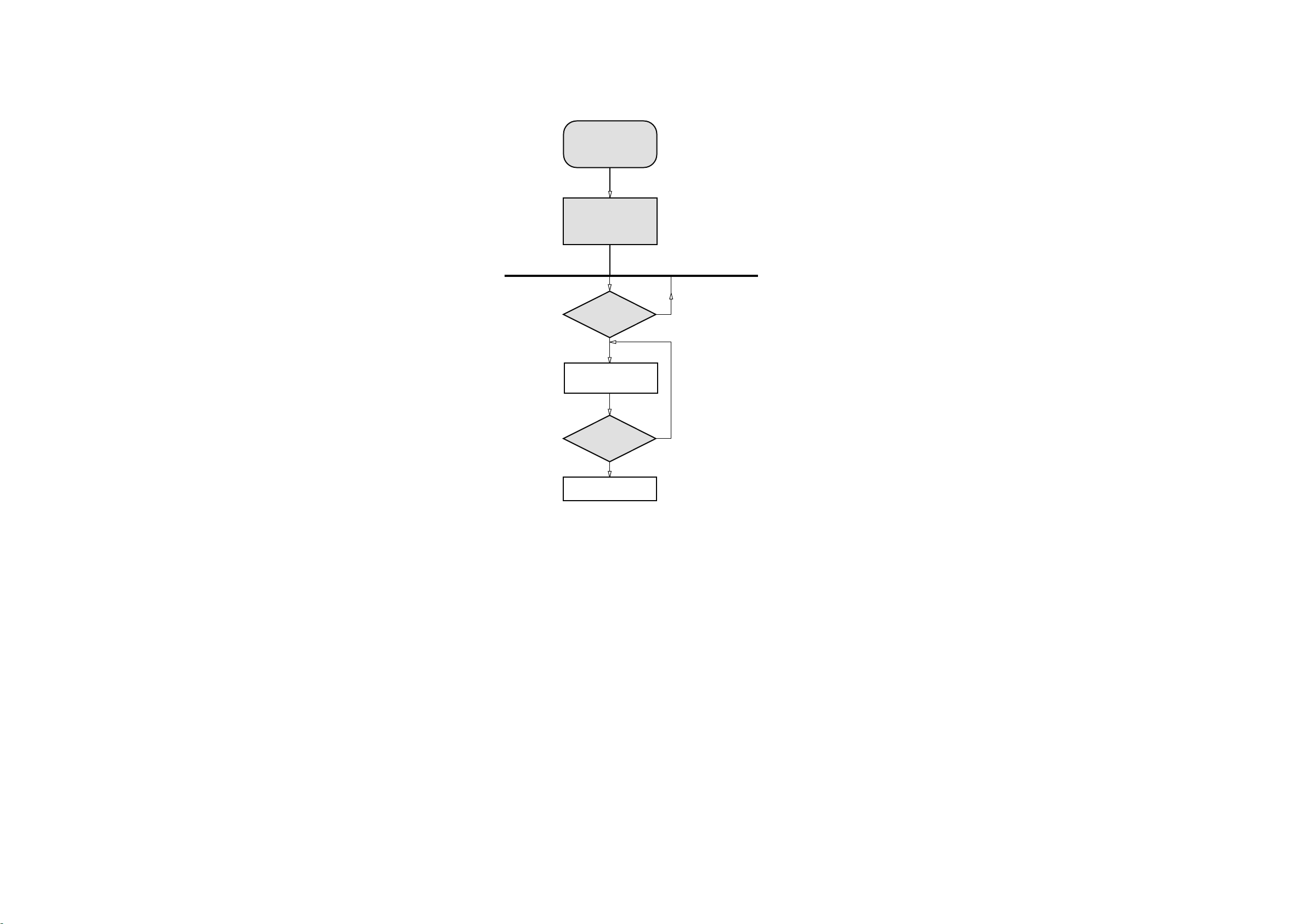
SERVICE TEST PROGRAM
2-1
To start service test program
hold PRESET+ & VOLUME+
depressed while
plugging in the mains cord
Display shows the
R
OM version *
"Vxxx"
DISPLAY
TEST
T
Button pressed?
Y
V refers to Version.
xxx refers to Software version number of µProcessor.
(Counting up from 001 to 099)
N
2-1
Display shows all LEDs on
VOL-
Button pressed?
Y
Set restored, Display shows
“CLr”
N
How to read USB fireware version:
1) Insert any USB device at USB mode.
2) Press PLAY/PAUSE button on Front Panel for 7 seconds, the display will shows yy ---> mmdd---> uu.
yy refers to year.
mmdd refers to
month & date.
uu refers to Software version number of USB.
How to upgrade USB fireware:
1) Insert the USB device which contains new version software at USB mode.
2) Press SOURCE button on Front Panel for 10 seconds, the display will shows ISP. Then OTI IC will be upgraded automatically within 15 seconds.

SET BLOCK DIAGRAM
3 - 1
3 - 1

SET WIRING DIAGRAM
4 - 1
4 - 1

CIRCUIT DIAGRAM - MCU & USB BOARD
MCU SECTION
5 - 1
5 - 1
 Loading...