

Page 1

Philips CMS Patient Monitoring System
Service Guide
PAD
Part No. M1046-9423L
Printed September 2002
Page 2

Notice
This document contains proprietary information which is protected by copyright. All
Rights Reserved. Reproduction, adaptation, or translation withou t prio r written
permission is prohibited, except as allowed under the copyright laws.
Philips Medical Systems
Cardiac and Monitoring Systems
3000 Minuteman Road
Andover, MA 01810
+1 (800) 934-7372
Publication number
M1046-9423L
Printed in Germany
Warranty The information contained in this document is subject to change without notice.
Philips makes no warranty of any kind with regard to this material, including, but not
limited to, the implied warranties or merchantability and fitness for a particular
purpose.
Philips shall not be liable for errors contained herein or for incidental or consequential
damages in connection with the furnishing, performance, or use of this material.
© 2002 Philips Medizin Systeme Böblingen GmbH
All rights are reserved.
Reproduction in whole or in part is prohibited without the prior written consent of the
copyright holder.
ii
Page 3

Printing History
New editions of this document will incorporate all material updated since the
previous edition. Update packages may be issued between editions and contain
replacement and additional pages to be merged by a revision date at the bottom of the
page. Note that pages which are rearranged due to changes on a previous page are not
considered revised.
The documentation printing date and part number indicate its current edition. The
printing date and part number change when a new edition is printed.
Part Number M1046-9303F
First Edition ............................... ...... ....January 1996
Part Number M1046-9303G
Second Edition.....................................May 1997
Part Number M1046-9088G
Third Edition........................................January 1998
Part Number M1046-9303H
Fourth Edition......................................June 1998
Part Number M1046-9303K
Fifth Edition.........................................March 1999
Part Number M1046-9303L
Sixth Edition ........................................June 2000
Part Number M1046-9423L
Seventh Edition....................................September 2002
iii
Page 4

Overview
Introduction The Philips CMS Patient Monitoring System Service Guide is a reference guide
featuring six chapters on how to test, troubleshoot, and repair the instrument.
The Philips CMS Patient Monitoring System and the Philips Anesthesia CMS Patient
Monitoring System, as well as the Philips Neonatal CMS Patient Monitoring System
will be referred to throughout this guide as the CMS.
Target Audience This reference guide is intended for hospital Biomedical Engineers and Technicians,
Philips Customer Engineers, Response Center Engineers, and Install a tion Planning
Specialists who have experience servicing Philips patient monitoring devices or
similar products.
Prerequisites In addition to this guide we recommend you to complete the Philips Patient Mon it or s
– Concepts Guide also contained in the Service Training Kit.
Course Objectives This guides objectives are:
• Identify the major units of CMS.
• Identify the controls and connectors of the major units of CMS.
• Identify the four operating modes of CMS.
• Connect the cabling of the CMS.
• Complete a Quick Check of the system.
• Perform Safety checks.
• Perform recommended maintenance.
• Perform a general inspection of the system.
• Clean the major units of the CMS.
• Perform Self-check procedures for CMS modules.
• Recognize a properly operating CMS.
• Identify symptoms of improper operation for the CMS.
• Use any symptoms or indications to identify a fault as being in the display
module, computer module, or the plug-in parameter modules.
• Further isolate faults down to field-replaceable assemblies.
• Locate and understand the removal and replacement procedures for the CMS and
ACMS.
• Provide a list of available parts for the CMS and ACMS.
iv
Page 5

In This Guide
Chapter 1 - Introducing the CMS provides a physical/functional overview of the
monitor.
Chapter 2 - Testing & Maintaining the CMS describes h ow to test, m a intain and
check that the instrument operates in an optimum condition.
Chapter 3 - Troubleshooting the CMS provides troubleshooting and diagnostic
procedures for the monitor.
Chapter 4 - Troubleshooting the Plug-in Modules provides troubleshooting and
self-test procedures for the parameter modules.
Chapter 5 - Repairing the CMS includes removal and replacement procedures for
field replaceable parts.
Chapter 6 - Parts List for CMS lists replacement and exchange part numbers for the
instrument.
Appendix A - Product Information gives a listing of the options for the monitor.
Appendix B - Conversion Charts gives relative conversion information.
Appendix C - Philips 15210B Calibration Unit gives service and installati on
information for this instrument used in calibrating plug-in modules.
Appendix D - CPC Programming Tool Manual
Glossary gives relevant definitions for the system
Index gives an alphabetical listing the contents of the guide.
v
Page 6

How to Use this Guide
Each chapter begins with a title which is followed by three sections: an opening
statement, an objectives statement and a concepts listing. These three sections can be
thought of as your guide to the chapter. They will tell you what you are going to find
in the chapter, what you should take away from the chapter in the way of goals and
terms, and concepts central to the chapter.
Chapters containing procedures will then proceed with a procedure overview table
and the body of the chapter. The procedure overview table is your guide to the actual
procedures in the chapter. It is designed to be used by an experienced user who needs
a quick review of the procedure or a page number of a particular procedure.
The body of the chapter will cover all of the procedures associated with the task. In
order to make the procedure easier to follow, we have kept the body of the text
focused on the procedure at hand and pulled the extra information, which might be
helpful to a new engineer, into the outside column. Here is a formatting example:
___________________________________________________________________
Example: Inspect the System Hardware
Inspecting the system
on an annual basis
will help you keep
track of your system
and identify pote ntial
parts that need to be
replaced.
No tools are required to perform this inspection.
Step 1 Examine the exterior of the unit for cleanliness and general physical
condition. Check that the plastic housings are intact, that all
hardware is present and tight, and that there are no signs of spilled
liquids or other serious abuse.
Step 2 Check fuse values and type against that marked on the chassis, and
ensure that a spare is provided.
Step 3 Inspect connectors of the module rack and ensure that the plug-in
modules are locked into place and do not slide out without first
releasing the locking plate on the bottom of the module.
Step 4 Ensure all labeling is present and legible.
Step 5 Inspect all accessories external to the system such as transducers,
referring to the manufacturer’s documentation.
___________________________________________________________________
vi
Page 7

vii
Page 8

viii
Page 9

Table of Contents
1. Introducing the CMS . . . . . . . . . . . . . . . . . . . . . . . . . . . . . . . . . . . . . . . . . . . . . . . . . . . . . . . .1-1
Objectives . . . . . . . . . . . . . . . . . . . . . . . . . . . . . . . . . . . . . . . . . . . . . . . . . . . . . . . . . . . . . . . . . . . . . . . . . . . . . . . .1-1
Concepts . . . . . . . . . . . . . . . . . . . . . . . . . . . . . . . . . . . . . . . . . . . . . . . . . . . . . . . . . . . . . . . . . . . . . . . . . . . . . . . . .1-2
Main Display Module. . . . . . . . . . . . . . . . . . . . . . . . . . . . . . . . . . . . . . . . . . . . . . . . . . . . . . . . . . . . . . . . . . . . . . .1-4
Objective . . . . . . . . . . . . . . . . . . . . . . . . . . . . . . . . . . . . . . . . . . . . . . . . . . . . . . . . . . . . . . . . . . . . . . . . . . . . .1-4
Concepts . . . . . . . . . . . . . . . . . . . . . . . . . . . . . . . . . . . . . . . . . . . . . . . . . . . . . . . . . . . . . . . . . . . . . . . . . . . . .1-4
Front Panel Controls and Connectors – CRT Display. . . . . . . . . . . . . . . . . . . . . . . . . . . . . . . . . . . . . . . . . . .1-7
Front Panel Controls and Connectors – Flatscreen Display . . . . . . . . . . . . . . . . . . . . . . . . . . . . . . . . . . . . . .1-8
Rear Panel Controls and Connectors. . . . . . . . . . . . . . . . . . . . . . . . . . . . . . . . . . . . . . . . . . . . . . . . . . . . . . .1-11
Slave Display Module. . . . . . . . . . . . . . . . . . . . . . . . . . . . . . . . . . . . . . . . . . . . . . . . . . . . . . . . . . . . . . . . . . . . . .1-13
14" Slave Display Front Panel Controls . . . . . . . . . . . . . . . . . . . . . . . . . . . . . . . . . . . . . . . . . . . . . . . . . . . .1-14
14" Slave Display Rear Panel Controls and Connectors. . . . . . . . . . . . . . . . . . . . . . . . . . . . . . . . . . . . . . . .1-14
Handheld Keypad . . . . . . . . . . . . . . . . . . . . . . . . . . . . . . . . . . . . . . . . . . . . . . . . . . . . . . . . . . . . . . . . . . . . . . . . .1-16
Objective . . . . . . . . . . . . . . . . . . . . . . . . . . . . . . . . . . . . . . . . . . . . . . . . . . . . . . . . . . . . . . . . . . . . . . . . . . . .1-16
Concepts . . . . . . . . . . . . . . . . . . . . . . . . . . . . . . . . . . . . . . . . . . . . . . . . . . . . . . . . . . . . . . . . . . . . . . . . . . . .1-16
Handheld Keypad Membrane Keyboard. . . . . . . . . . . . . . . . . . . . . . . . . . . . . . . . . . . . . . . . . . . . . . . . . . . .1-17
Handheld Keypad Rear Cover. . . . . . . . . . . . . . . . . . . . . . . . . . . . . . . . . . . . . . . . . . . . . . . . . . . . . . . . . . . .1-18
External Alarm Device M1109A. . . . . . . . . . . . . . . . . . . . . . . . . . . . . . . . . . . . . . . . . . . . . . . . . . . . . . . . . .1-18
Computer Module. . . . . . . . . . . . . . . . . . . . . . . . . . . . . . . . . . . . . . . . . . . . . . . . . . . . . . . . . . . . . . . . . . . . . . . . .1-19
Objective . . . . . . . . . . . . . . . . . . . . . . . . . . . . . . . . . . . . . . . . . . . . . . . . . . . . . . . . . . . . . . . . . . . . . . . . . . . .1-19
Concepts . . . . . . . . . . . . . . . . . . . . . . . . . . . . . . . . . . . . . . . . . . . . . . . . . . . . . . . . . . . . . . . . . . . . . . . . . . . .1-19
Brief Functional Overview . . . . . . . . . . . . . . . . . . . . . . . . . . . . . . . . . . . . . . . . . . . . . . . . . . . . . . . . . . . . . .1-20
Delivered Configurations. . . . . . . . . . . . . . . . . . . . . . . . . . . . . . . . . . . . . . . . . . . . . . . . . . . . . . . . . . . . . . . .1-21
Function Cards of the Computer Module . . . . . . . . . . . . . . . . . . . . . . . . . . . . . . . . . . . . . . . . . . . . . . . . . . .1-21
Function Card Placement. . . . . . . . . . . . . . . . . . . . . . . . . . . . . . . . . . . . . . . . . . . . . . . . . . . . . . . . . . . . . . . .1-22
EEPROM Numbers . . . . . . . . . . . . . . . . . . . . . . . . . . . . . . . . . . . . . . . . . . . . . . . . . . . . . . . . . . . . . . . . . . . .1-28
Front Connectors . . . . . . . . . . . . . . . . . . . . . . . . . . . . . . . . . . . . . . . . . . . . . . . . . . . . . . . . . . . . . . . . . . . . . .1-33
Rear Connectors. . . . . . . . . . . . . . . . . . . . . . . . . . . . . . . . . . . . . . . . . . . . . . . . . . . . . . . . . . . . . . . . . . . . . . .1-35
Computer Module External Connector Pinouts. . . . . . . . . . . . . . . . . . . . . . . . . . . . . . . . . . . . . . . . . . . . . . .1-36
Mounting the CMS . . . . . . . . . . . . . . . . . . . . . . . . . . . . . . . . . . . . . . . . . . . . . . . . . . . . . . . . . . . . . . . . . . . . . . . .1-39
Connecting the CMS Cables. . . . . . . . . . . . . . . . . . . . . . . . . . . . . . . . . . . . . . . . . . . . . . . . . . . . . . . . . . . . . . . . .1-39
To Connect the Computer Module and Plug-in Module Rack . . . . . . . . . . . . . . . . . . . . . . . . . . . . . . . . . . .1-39
To Connect the CRT Display to the Computer Module . . . . . . . . . . . . . . . . . . . . . . . . . . . . . . . . . . . . . . . .1-41
To Connect the Flatscreen Display to the Computer Module . . . . . . . . . . . . . . . . . . . . . . . . . . . . . . . . .1-42
To Connect the XGA-Compatible Display to the Computer Module. . . . . . . . . . . . . . . . . . . . . . . . . . . . . .1-42
To Connect the Satellite Rack . . . . . . . . . . . . . . . . . . . . . . . . . . . . . . . . . . . . . . . . . . . . . . . . . . . . . . . . . . . .1-42
To Connect the Strip Recorder . . . . . . . . . . . . . . . . . . . . . . . . . . . . . . . . . . . . . . . . . . . . . . . . . . . . . . . . . . .1-42
To Connect the Handheld Keypad to the CRT Display Module. . . . . . . . . . . . . . . . . . . . . . . . . . . . . . . . . .1-42
To Connect the Handheld Keypad to the External Alarm Device . . . . . . . . . . . . . . . . . . . . . . . . . . . . . . . . 1 -43
To Connect the External Alarm Device to the Computer Module . . . . . . . . . . . . . . . . . . . . . . . . . . . . . . . .1-43
To Connect Printers and PCs. . . . . . . . . . . . . . . . . . . . . . . . . . . . . . . . . . . . . . . . . . . . . . . . . . . . . . . . . . . . . 1 -43
Configuring and Adjusting Displays . . . . . . . . . . . . . . . . . . . . . . . . . . . . . . . . . . . . . . . . . . . . . . . . . . . . . . . . . .1-45
Introduction . . . . . . . . . . . . . . . . . . . . . . . . . . . . . . . . . . . . . . . . . . . . . . . . . . . . . . . . . . . . . . . . . . . . . . . . . .1-45
Configuring the RS-232 Port. . . . . . . . . . . . . . . . . . . . . . . . . . . . . . . . . . . . . . . . . . . . . . . . . . . . . . . . . . . . .1-45
XGA Display Adjustments . . . . . . . . . . . . . . . . . . . . . . . . . . . . . . . . . . . . . . . . . . . . . . . . . . . . . . . . . . . . . .1-46
Calibrating the Touch Screen . . . . . . . . . . . . . . . . . . . . . . . . . . . . . . . . . . . . . . . . . . . . . . . . . . . . . . . . . . . .1-47
Performing the Functionality Test. . . . . . . . . . . . . . . . . . . . . . . . . . . . . . . . . . . . . . . . . . . . . . . . . . . . . . . . .1-48
Configuring the Mouse or Trackball . . . . . . . . . . . . . . . . . . . . . . . . . . . . . . . . . . . . . . . . . . . . . . . . . . . . . . . . . .1-49
Introduction . . . . . . . . . . . . . . . . . . . . . . . . . . . . . . . . . . . . . . . . . . . . . . . . . . . . . . . . . . . . . . . . . . . . . . . . . .1-49
Configuring the RS-232 Port. . . . . . . . . . . . . . . . . . . . . . . . . . . . . . . . . . . . . . . . . . . . . . . . . . . . . . . . . . . . .1-49
Performing the Functionality Test. . . . . . . . . . . . . . . . . . . . . . . . . . . . . . . . . . . . . . . . . . . . . . . . . . . . . . . . .1-49
Contents-ix
Page 10

Adjusting the Pointer Speed of the Mouse or Trackball (Optional). . . . . . . . . . . . . . . . . . . . . . . . . . . . . . . 1-50
Integral Power Supply - Computer Module (M1046B). . . . . . . . . . . . . . . . . . . . . . . . . . . . . . . . . . . . . . . . . . . . 1-51
Integral Power Supply - Connectors and Controls . . . . . . . . . . . . . . . . . . . . . . . . . . . . . . . . . . . . . . . . . . . . 1-51
Remote Power Supply . . . . . . . . . . . . . . . . . . . . . . . . . . . . . . . . . . . . . . . . . . . . . . . . . . . . . . . . . . . . . . . . . . . . . 1-52
Front Panel Controls - Remote Power Supply . . . . . . . . . . . . . . . . . . . . . . . . . . . . . . . . . . . . . . . . . . . . . . . 1-52
Remote Power Supply - Rear Controls and Connectors. . . . . . . . . . . . . . . . . . . . . . . . . . . . . . . . . . . . . . . . 1-53
Fuse Values . . . . . . . . . . . . . . . . . . . . . . . . . . . . . . . . . . . . . . . . . . . . . . . . . . . . . . . . . . . . . . . . . . . . . . . . . . . . . 1-54
Plug-in Module Racks . . . . . . . . . . . . . . . . . . . . . . . . . . . . . . . . . . . . . . . . . . . . . . . . . . . . . . . . . . . . . . . . . . . . . 1-55
Objective. . . . . . . . . . . . . . . . . . . . . . . . . . . . . . . . . . . . . . . . . . . . . . . . . . . . . . . . . . . . . . . . . . . . . . . . . . . . 1-55
Concepts . . . . . . . . . . . . . . . . . . . . . . . . . . . . . . . . . . . . . . . . . . . . . . . . . . . . . . . . . . . . . . . . . . . . . . . . . . . . 1-55
Front and Rear Connectors. . . . . . . . . . . . . . . . . . . . . . . . . . . . . . . . . . . . . . . . . . . . . . . . . . . . . . . . . . . . . . 1-56
Plug-in Modules. . . . . . . . . . . . . . . . . . . . . . . . . . . . . . . . . . . . . . . . . . . . . . . . . . . . . . . . . . . . . . . . . . . . . . . . . . 1-58
Objective. . . . . . . . . . . . . . . . . . . . . . . . . . . . . . . . . . . . . . . . . . . . . . . . . . . . . . . . . . . . . . . . . . . . . . . . . . . . 1-58
Concepts . . . . . . . . . . . . . . . . . . . . . . . . . . . . . . . . . . . . . . . . . . . . . . . . . . . . . . . . . . . . . . . . . . . . . . . . . . . . 1-58
Plug-In Module Control Panel Keys and Indicators. . . . . . . . . . . . . . . . . . . . . . . . . . . . . . . . . . . . . . . . . . . 1-59
Plug-in Module Pin-outs. . . . . . . . . . . . . . . . . . . . . . . . . . . . . . . . . . . . . . . . . . . . . . . . . . . . . . . . . . . . . . . . 1-63
Operating Modes . . . . . . . . . . . . . . . . . . . . . . . . . . . . . . . . . . . . . . . . . . . . . . . . . . . . . . . . . . . . . . . . . . . . . . . . . 1-65
Objective. . . . . . . . . . . . . . . . . . . . . . . . . . . . . . . . . . . . . . . . . . . . . . . . . . . . . . . . . . . . . . . . . . . . . . . . . . . . 1-65
Concepts . . . . . . . . . . . . . . . . . . . . . . . . . . . . . . . . . . . . . . . . . . . . . . . . . . . . . . . . . . . . . . . . . . . . . . . . . . . . 1-65
Operating Rules to Remember . . . . . . . . . . . . . . . . . . . . . . . . . . . . . . . . . . . . . . . . . . . . . . . . . . . . . . . . . . . 1-66
Identifying Monitoring Mode. . . . . . . . . . . . . . . . . . . . . . . . . . . . . . . . . . . . . . . . . . . . . . . . . . . . . . . . . . . . 1-66
Identifying Demo Mode . . . . . . . . . . . . . . . . . . . . . . . . . . . . . . . . . . . . . . . . . . . . . . . . . . . . . . . . . . . . . . . . 1-66
Identifying Configuration Mode. . . . . . . . . . . . . . . . . . . . . . . . . . . . . . . . . . . . . . . . . . . . . . . . . . . . . . . . . . 1-67
Identifying Service Mode . . . . . . . . . . . . . . . . . . . . . . . . . . . . . . . . . . . . . . . . . . . . . . . . . . . . . . . . . . . . . . . 1-67
Changing Operating Modes . . . . . . . . . . . . . . . . . . . . . . . . . . . . . . . . . . . . . . . . . . . . . . . . . . . . . . . . . . . . . 1-68
2. Testing & Maintaining the CMS . . . . . . . . . . . . . . . . . . . . . . . . . . . . . . . . . . . . . . . . . . . . . .2-1
Objectives. . . . . . . . . . . . . . . . . . . . . . . . . . . . . . . . . . . . . . . . . . . . . . . . . . . . . . . . . . . . . . . . . . . . . . . . . . . . . . . . 2-1
Concepts. . . . . . . . . . . . . . . . . . . . . . . . . . . . . . . . . . . . . . . . . . . . . . . . . . . . . . . . . . . . . . . . . . . . . . . . . . . . . . . . . 2-1
Procedure Overview. . . . . . . . . . . . . . . . . . . . . . . . . . . . . . . . . . . . . . . . . . . . . . . . . . . . . . . . . . . . . . . . . . . . . . . . 2-2
Test and Inspection Requirements. . . . . . . . . . . . . . . . . . . . . . . . . . . . . . . . . . . . . . . . . . . . . . . . . . . . . . . . . . . . . 2-3
Safety Tests . . . . . . . . . . . . . . . . . . . . . . . . . . . . . . . . . . . . . . . . . . . . . . . . . . . . . . . . . . . . . . . . . . . . . . . . . . 2-11
Preventive Maintenance Procedure for the Philips M1180A #A01 and #A02 Wall Mount Assembly. . . . . . . . 2-15
Overview. . . . . . . . . . . . . . . . . . . . . . . . . . . . . . . . . . . . . . . . . . . . . . . . . . . . . . . . . . . . . . . . . . . . . . . . . . . . 2-15
Step 1: Inspect visible fasteners . . . . . . . . . . . . . . . . . . . . . . . . . . . . . . . . . . . . . . . . . . . . . . . . . . . . . . . . . . 2-15
Step 2: Check maximum tilt range . . . . . . . . . . . . . . . . . . . . . . . . . . . . . . . . . . . . . . . . . . . . . . . . . . . . . . . . 2-17
Step 3: Inspect mounting plate for movement . . . . . . . . . . . . . . . . . . . . . . . . . . . . . . . . . . . . . . . . . . . . . . . 2-17
General Inspections of the System. . . . . . . . . . . . . . . . . . . . . . . . . . . . . . . . . . . . . . . . . . . . . . . . . . . . . . . . . . . . 2-19
Objective. . . . . . . . . . . . . . . . . . . . . . . . . . . . . . . . . . . . . . . . . . . . . . . . . . . . . . . . . . . . . . . . . . . . . . . . . . . . 2-19
Concepts . . . . . . . . . . . . . . . . . . . . . . . . . . . . . . . . . . . . . . . . . . . . . . . . . . . . . . . . . . . . . . . . . . . . . . . . . . . . 2-19
Inspect the System Hardware . . . . . . . . . . . . . . . . . . . . . . . . . . . . . . . . . . . . . . . . . . . . . . . . . . . . . . . . . . . . 2-19
Inspect the Cables. . . . . . . . . . . . . . . . . . . . . . . . . . . . . . . . . . . . . . . . . . . . . . . . . . . . . . . . . . . . . . . . . . . . . 2-20
Inspect the Red Power Indicators (LEDs) of the System . . . . . . . . . . . . . . . . . . . . . . . . . . . . . . . . . . . . . . . 2-20
Inspect the Display CRT / LCD . . . . . . . . . . . . . . . . . . . . . . . . . . . . . . . . . . . . . . . . . . . . . . . . . . . . . . . . . . 2-21
Inspect the Controls of the System. . . . . . . . . . . . . . . . . . . . . . . . . . . . . . . . . . . . . . . . . . . . . . . . . . . . . . . . 2-22
Cleaning and Disinfecting Procedures. . . . . . . . . . . . . . . . . . . . . . . . . . . . . . . . . . . . . . . . . . . . . . . . . . . . . . . . . 2-23
Objective. . . . . . . . . . . . . . . . . . . . . . . . . . . . . . . . . . . . . . . . . . . . . . . . . . . . . . . . . . . . . . . . . . . . . . . . . . . . 2-23
Concepts . . . . . . . . . . . . . . . . . . . . . . . . . . . . . . . . . . . . . . . . . . . . . . . . . . . . . . . . . . . . . . . . . . . . . . . . . . . . 2-23
General Cleaning of the System. . . . . . . . . . . . . . . . . . . . . . . . . . . . . . . . . . . . . . . . . . . . . . . . . . . . . . . . . . 2-24
General Disinfecting of the System . . . . . . . . . . . . . . . . . . . . . . . . . . . . . . . . . . . . . . . . . . . . . . . . . . . . . . . 2-25
x
Page 11

Cleaning the Recorder Module . . . . . . . . . . . . . . . . . . . . . . . . . . . . . . . . . . . . . . . . . . . . . . . . . . . . . . . . . . .2-26
Cleaning the Blood Analysis Module . . . . . . . . . . . . . . . . . . . . . . . . . . . . . . . . . . . . . . . . . . . . . . . . . . . . . .2-27
3. Troubleshooting the CMS . . . . . . . . . . . . . . . . . . . . . . . . . . . . . . . . . . . . . . . . . . . . . . . . . . . .3-1
Objectives . . . . . . . . . . . . . . . . . . . . . . . . . . . . . . . . . . . . . . . . . . . . . . . . . . . . . . . . . . . . . . . . . . . . . . . . . . . . . . . .3-1
Concepts . . . . . . . . . . . . . . . . . . . . . . . . . . . . . . . . . . . . . . . . . . . . . . . . . . . . . . . . . . . . . . . . . . . . . . . . . . . . . . . . .3-1
Procedure Overview . . . . . . . . . . . . . . . . . . . . . . . . . . . . . . . . . . . . . . . . . . . . . . . . . . . . . . . . . . . . . . . . . . . . . . . .3-2
General System Troubleshooting . . . . . . . . . . . . . . . . . . . . . . . . . . . . . . . . . . . . . . . . . . . . . . . . . . . . . . . . . . . . . .3-3
Objectives . . . . . . . . . . . . . . . . . . . . . . . . . . . . . . . . . . . . . . . . . . . . . . . . . . . . . . . . . . . . . . . . . . . . . . . . . . . . . . . .3-7
Concepts . . . . . . . . . . . . . . . . . . . . . . . . . . . . . . . . . . . . . . . . . . . . . . . . . . . . . . . . . . . . . . . . . . . . . . . . . . . . . . . . .3-7
Procedures. . . . . . . . . . . . . . . . . . . . . . . . . . . . . . . . . . . . . . . . . . . . . . . . . . . . . . . . . . . . . . . . . . . . . . . . . . . . . . . .3-8
Objectives . . . . . . . . . . . . . . . . . . . . . . . . . . . . . . . . . . . . . . . . . . . . . . . . . . . . . . . . . . . . . . . . . . . . . . . . . . . . . . .3-14
Concepts . . . . . . . . . . . . . . . . . . . . . . . . . . . . . . . . . . . . . . . . . . . . . . . . . . . . . . . . . . . . . . . . . . . . . . . . . . . . . . . .3-14
Error Codes . . . . . . . . . . . . . . . . . . . . . . . . . . . . . . . . . . . . . . . . . . . . . . . . . . . . . . . . . . . . . . . . . . . . . . . . . .3-14
What an Error Code Tells You . . . . . . . . . . . . . . . . . . . . . . . . . . . . . . . . . . . . . . . . . . . . . . . . . . . . . . . . . . .3-15
Using Error Codes . . . . . . . . . . . . . . . . . . . . . . . . . . . . . . . . . . . . . . . . . . . . . . . . . . . . . . . . . . . . . . . . . . . . . . . .3-15
Using Status Log Error Codes. . . . . . . . . . . . . . . . . . . . . . . . . . . . . . . . . . . . . . . . . . . . . . . . . . . . . . . . . . . .3-16
Using Start-up Error Codes. . . . . . . . . . . . . . . . . . . . . . . . . . . . . . . . . . . . . . . . . . . . . . . . . . . . . . . . . . . . . .3-16
How Device ID Codes and Error Codes Relate to Each Other . . . . . . . . . . . . . . . . . . . . . . . . . . . . . . . . . . .3-17
Identifying the Slot Number Using the Error Code Chart. . . . . . . . . . . . . . . . . . . . . . . . . . . . . . . . . . . . . . .3-17
Device ID 16400 (or 4010H) Error Code Lists. . . . . . . . . . . . . . . . . . . . . . . . . . . . . . . . . . . . . . . . . . . . . . .3-18
CMS System Hardware Configuration Problems. . . . . . . . . . . . . . . . . . . . . . . . . . . . . . . . . . . . . . . . . . . . . . . . .3-23
Concepts . . . . . . . . . . . . . . . . . . . . . . . . . . . . . . . . . . . . . . . . . . . . . . . . . . . . . . . . . . . . . . . . . . . . . . . . . . . .3-23
Rules for Card Placement . . . . . . . . . . . . . . . . . . . . . . . . . . . . . . . . . . . . . . . . . . . . . . . . . . . . . . . . . . . . . . .3-24
Procedures . . . . . . . . . . . . . . . . . . . . . . . . . . . . . . . . . . . . . . . . . . . . . . . . . . . . . . . . . . . . . . . . . . . . . . . . . . .3-25
CMS System Hardware/Software Problems. . . . . . . . . . . . . . . . . . . . . . . . . . . . . . . . . . . . . . . . . . . . . . . . . . . . .3-27
Procedures . . . . . . . . . . . . . . . . . . . . . . . . . . . . . . . . . . . . . . . . . . . . . . . . . . . . . . . . . . . . . . . . . . . . . . . . . . .3-27
Loudspeaker Test at Power On . . . . . . . . . . . . . . . . . . . . . . . . . . . . . . . . . . . . . . . . . . . . . . . . . . . . . . . . . . .3-27
CMS System RAM Problems. . . . . . . . . . . . . . . . . . . . . . . . . . . . . . . . . . . . . . . . . . . . . . . . . . . . . . . . . . . . . . . .3-27
Error Code Lists for Other Device IDs . . . . . . . . . . . . . . . . . . . . . . . . . . . . . . . . . . . . . . . . . . . . . . . . . . . . .3-28
Error Code List for Specific Device IDs other than 16400 (4010H). . . . . . . . . . . . . . . . . . . . . . . . . . . . . . .3-30
Device ID Codes for Software. . . . . . . . . . . . . . . . . . . . . . . . . . . . . . . . . . . . . . . . . . . . . . . . . . . . . . . . . . . .3-33
Local Jet Printer Configurations . . . . . . . . . . . . . . . . . . . . . . . . . . . . . . . . . . . . . . . . . . . . . . . . . . . . . . . . . .3-37
Accessing & Leaving Service Mode . . . . . . . . . . . . . . . . . . . . . . . . . . . . . . . . . . . . . . . . . . . . . . . . . . . . . . . . . .3-39
Facilities Available in the Service Mode . . . . . . . . . . . . . . . . . . . . . . . . . . . . . . . . . . . . . . . . . . . . . . . . . . . . . . .3-40
Changing the Global Switches. . . . . . . . . . . . . . . . . . . . . . . . . . . . . . . . . . . . . . . . . . . . . . . . . . . . . . . . . . . .3-40
Line Frequency . . . . . . . . . . . . . . . . . . . . . . . . . . . . . . . . . . . . . . . . . . . . . . . . . . . . . . . . . . . . . . . . . . . . . . .3-40
Control Panel Software . . . . . . . . . . . . . . . . . . . . . . . . . . . . . . . . . . . . . . . . . . . . . . . . . . . . . . . . . . . . . . . . .3-41
Settings Transfer . . . . . . . . . . . . . . . . . . . . . . . . . . . . . . . . . . . . . . . . . . . . . . . . . . . . . . . . . . . . . . . . . . . . . .3-41
Setting the Altitude . . . . . . . . . . . . . . . . . . . . . . . . . . . . . . . . . . . . . . . . . . . . . . . . . . . . . . . . . . . . . . . . . . . .3-42
Setting the Date and Time. . . . . . . . . . . . . . . . . . . . . . . . . . . . . . . . . . . . . . . . . . . . . . . . . . . . . . . . . . . . . . .3-42
French Homologation (French language CMS only) . . . . . . . . . . . . . . . . . . . . . . . . . . . . . . . . . . . . . . . . . .3-42
Displaying the Status Log . . . . . . . . . . . . . . . . . . . . . . . . . . . . . . . . . . . . . . . . . . . . . . . . . . . . . . . . . . . . . . .3-42
RS-232 Interface . . . . . . . . . . . . . . . . . . . . . . . . . . . . . . . . . . . . . . . . . . . . . . . . . . . . . . . . . . . . . . . . . . . . . .3-42
Checking the Hardware and Software Revisions . . . . . . . . . . . . . . . . . . . . . . . . . . . . . . . . . . . . . . . . . . . . .3-43
Power On Modes. . . . . . . . . . . . . . . . . . . . . . . . . . . . . . . . . . . . . . . . . . . . . . . . . . . . . . . . . . . . . . . . . . . . . .3-44
Display Alignment Patterns . . . . . . . . . . . . . . . . . . . . . . . . . . . . . . . . . . . . . . . . . . . . . . . . . . . . . . . . . . . . . .3-44
Network Test . . . . . . . . . . . . . . . . . . . . . . . . . . . . . . . . . . . . . . . . . . . . . . . . . . . . . . . . . . . . . . . . . . . . . . . . .3-45
Description of the Boot Process . . . . . . . . . . . . . . . . . . . . . . . . . . . . . . . . . . . . . . . . . . . . . . . . . . . . . . . . . . . . . .3-48
Overview . . . . . . . . . . . . . . . . . . . . . . . . . . . . . . . . . . . . . . . . . . . . . . . . . . . . . . . . . . . . . . . . . . . . . . . . . . . .3-48
xi
Page 12

Summary of the Power On Modes . . . . . . . . . . . . . . . . . . . . . . . . . . . . . . . . . . . . . . . . . . . . . . . . . . . . . . . . 3-49
4. Troubleshooting the Plug-in Modules . . . . . . . . . . . . . . . . . . . . . . . . . . . . . . . . . . . . . . . . . .4-1
Objectives. . . . . . . . . . . . . . . . . . . . . . . . . . . . . . . . . . . . . . . . . . . . . . . . . . . . . . . . . . . . . . . . . . . . . . . . . . . . . . . . 4-1
Concepts. . . . . . . . . . . . . . . . . . . . . . . . . . . . . . . . . . . . . . . . . . . . . . . . . . . . . . . . . . . . . . . . . . . . . . . . . . . . . . . . . 4-1
Procedure Overview. . . . . . . . . . . . . . . . . . . . . . . . . . . . . . . . . . . . . . . . . . . . . . . . . . . . . . . . . . . . . . . . . . . . . . . . 4-2
Troubleshooting tcpO
To Troubleshoot the Module . . . . . . . . . . . . . . . . . . . . . . . . . . . . . . . . . . . . . . . . . . . . . . . . . . . . . . . . . . . . . 4-3
Test Equipment. . . . . . . . . . . . . . . . . . . . . . . . . . . . . . . . . . . . . . . . . . . . . . . . . . . . . . . . . . . . . . . . . . . . . . . . 4-7
Procedure . . . . . . . . . . . . . . . . . . . . . . . . . . . . . . . . . . . . . . . . . . . . . . . . . . . . . . . . . . . . . . . . . . . . . . . . . . . . 4-7
Troubleshooting ECG and ECG/RESP Problems . . . . . . . . . . . . . . . . . . . . . . . . . . . . . . . . . . . . . . . . . . . . . . . . . 4-9
To Troubleshoot the Module . . . . . . . . . . . . . . . . . . . . . . . . . . . . . . . . . . . . . . . . . . . . . . . . . . . . . . . . . . . . . 4-9
Troubleshooting Pressure Problems. . . . . . . . . . . . . . . . . . . . . . . . . . . . . . . . . . . . . . . . . . . . . . . . . . . . . . . . . . . 4-11
To Troubleshoot the Module . . . . . . . . . . . . . . . . . . . . . . . . . . . . . . . . . . . . . . . . . . . . . . . . . . . . . . . . . . . . 4-11
Troubleshooting NBP Problems . . . . . . . . . . . . . . . . . . . . . . . . . . . . . . . . . . . . . . . . . . . . . . . . . . . . . . . . . . . . . 4-13
To Troubleshoot the Module . . . . . . . . . . . . . . . . . . . . . . . . . . . . . . . . . . . . . . . . . . . . . . . . . . . . . . . . . . . . 4-13
Using the Calibration Mode . . . . . . . . . . . . . . . . . . . . . . . . . . . . . . . . . . . . . . . . . . . . . . . . . . . . . . . . . . . . . 4-15
Selecting NBP Measurement Characteristic. . . . . . . . . . . . . . . . . . . . . . . . . . . . . . . . . . . . . . . . . . . . . . . . . 4-15
Troubleshooting Cardiac Output Problems . . . . . . . . . . . . . . . . . . . . . . . . . . . . . . . . . . . . . . . . . . . . . . . . . . . . . 4-17
To Troubleshoot the Module . . . . . . . . . . . . . . . . . . . . . . . . . . . . . . . . . . . . . . . . . . . . . . . . . . . . . . . . . . . . 4-17
Troubleshooting SpO
To Troubleshoot the Module . . . . . . . . . . . . . . . . . . . . . . . . . . . . . . . . . . . . . . . . . . . . . . . . . . . . . . . . . . . . 4-22
Troubleshooting SvO
To Troubleshoot the Module . . . . . . . . . . . . . . . . . . . . . . . . . . . . . . . . . . . . . . . . . . . . . . . . . . . . . . . . . . . . 4-24
Troubleshooting FIO
To Troubleshoot the Module . . . . . . . . . . . . . . . . . . . . . . . . . . . . . . . . . . . . . . . . . . . . . . . . . . . . . . . . . . . . 4-28
Troubleshooting Temperature Module Problems . . . . . . . . . . . . . . . . . . . . . . . . . . . . . . . . . . . . . . . . . . . . . . . . 4-30
To Troubleshoot the Module . . . . . . . . . . . . . . . . . . . . . . . . . . . . . . . . . . . . . . . . . . . . . . . . . . . . . . . . . . . . 4-30
Troubleshooting CO
To Troubleshoot the Module . . . . . . . . . . . . . . . . . . . . . . . . . . . . . . . . . . . . . . . . . . . . . . . . . . . . . . . . . . . . 4-32
Troubleshooting Blood Analysis Module Problems . . . . . . . . . . . . . . . . . . . . . . . . . . . . . . . . . . . . . . . . . . . . . . 4-35
To Troubleshoot the Module . . . . . . . . . . . . . . . . . . . . . . . . . . . . . . . . . . . . . . . . . . . . . . . . . . . . . . . . . . . . 4-35
Troubleshooting EEG Module Problems. . . . . . . . . . . . . . . . . . . . . . . . . . . . . . . . . . . . . . . . . . . . . . . . . . . . . . . 4-40
To Troubleshoot the Module . . . . . . . . . . . . . . . . . . . . . . . . . . . . . . . . . . . . . . . . . . . . . . . . . . . . . . . . . . . . 4-40
Troubleshooting BIS Module Problems . . . . . . . . . . . . . . . . . . . . . . . . . . . . . . . . . . . . . . . . . . . . . . . . . . . . . . . 4-43
To Troubleshoot the Module . . . . . . . . . . . . . . . . . . . . . . . . . . . . . . . . . . . . . . . . . . . . . . . . . . . . . . . . . . . . 4-43
General Test Procedures for the BIS components . . . . . . . . . . . . . . . . . . . . . . . . . . . . . . . . . . . . . . . . . . . . 4-48
Additional information available in the Service Mode Task Window. . . . . . . . . . . . . . . . . . . . . . . . . . . . . 4-49
Compatibility Matrix . . . . . . . . . . . . . . . . . . . . . . . . . . . . . . . . . . . . . . . . . . . . . . . . . . . . . . . . . . . . . . . . . . 4-51
Troubleshooting VueLink Module Problems . . . . . . . . . . . . . . . . . . . . . . . . . . . . . . . . . . . . . . . . . . . . . . . . . . . 4-52
M1032A VueLink Tests using VueLink Test Module. . . . . . . . . . . . . . . . . . . . . . . . . . . . . . . . . . . . . . . . . 4-52
Performing Plug-In Module Self-Tests . . . . . . . . . . . . . . . . . . . . . . . . . . . . . . . . . . . . . . . . . . . . . . . . . . . . . . . . 4-54
Objective. . . . . . . . . . . . . . . . . . . . . . . . . . . . . . . . . . . . . . . . . . . . . . . . . . . . . . . . . . . . . . . . . . . . . . . . . . . . 4-54
Concepts . . . . . . . . . . . . . . . . . . . . . . . . . . . . . . . . . . . . . . . . . . . . . . . . . . . . . . . . . . . . . . . . . . . . . . . . . . . . 4-54
Performing a Quick System Check. . . . . . . . . . . . . . . . . . . . . . . . . . . . . . . . . . . . . . . . . . . . . . . . . . . . . . . . 4-54
Self-Test Procedure Overview . . . . . . . . . . . . . . . . . . . . . . . . . . . . . . . . . . . . . . . . . . . . . . . . . . . . . . . . . . . 4-55
Performing the ECG or ECG/RESP Module Self-Test . . . . . . . . . . . . . . . . . . . . . . . . . . . . . . . . . . . . . . . . 4-57
Performing the M1006A/B Pressure Module Self-Test . . . . . . . . . . . . . . . . . . . . . . . . . . . . . . . . . . . . . . . . 4-57
Performing the NBP Module Self-Test . . . . . . . . . . . . . . . . . . . . . . . . . . . . . . . . . . . . . . . . . . . . . . . . . . . . 4-58
Performing the SpO
/tcpCO2 Problems . . . . . . . . . . . . . . . . . . . . . . . . . . . . . . . . . . . . . . . . . . . . . . . . . . . . . . . 4-3
2
/Pleth Problems . . . . . . . . . . . . . . . . . . . . . . . . . . . . . . . . . . . . . . . . . . . . . . . . . . . . . . . . 4-22
2
Problems . . . . . . . . . . . . . . . . . . . . . . . . . . . . . . . . . . . . . . . . . . . . . . . . . . . . . . . . . . . . . 4-24
2
Module Problems. . . . . . . . . . . . . . . . . . . . . . . . . . . . . . . . . . . . . . . . . . . . . . . . . . . . . . . 4-28
2
Module Problems . . . . . . . . . . . . . . . . . . . . . . . . . . . . . . . . . . . . . . . . . . . . . . . . . . . . . . . 4-32
2
/Pleth Module Self-Test . . . . . . . . . . . . . . . . . . . . . . . . . . . . . . . . . . . . . . . . . . . . . . . 4-58
2
xii
Page 13

Performing the Cardiac Output Module Self-Test. . . . . . . . . . . . . . . . . . . . . . . . . . . . . . . . . . . . . . . . . . . . .4-59
Performing the tcpO
Performing the SvO
Performing the SvO
Performing the FIO
Performing the CO
/tcpCO2 Module Self-Test. . . . . . . . . . . . . . . . . . . . . . . . . . . . . . . . . . . . . . . . . . . . . .4-59
2
Module Self-Test . . . . . . . . . . . . . . . . . . . . . . . . . . . . . . . . . . . . . . . . . . . . . . . . . . . .4-60
2
Optical Stability Check. . . . . . . . . . . . . . . . . . . . . . . . . . . . . . . . . . . . . . . . . . . . . . . .4-60
2
Module Self-Test. . . . . . . . . . . . . . . . . . . . . . . . . . . . . . . . . . . . . . . . . . . . . . . . . . . . .4-61
2
Module Self-Test . . . . . . . . . . . . . . . . . . . . . . . . . . . . . . . . . . . . . . . . . . . . . . . . . . . . .4-61
2
Performing the Temperature Module Self-Test. . . . . . . . . . . . . . . . . . . . . . . . . . . . . . . . . . . . . . . . . . . . . . . 4 -62
Performing the Blood Analysis Module Self-Test . . . . . . . . . . . . . . . . . . . . . . . . . . . . . . . . . . . . . . . . . . . .4-62
Performing the Recorder Module Self-Test . . . . . . . . . . . . . . . . . . . . . . . . . . . . . . . . . . . . . . . . . . . . . . . . .4-63
Performing the VueLink Module Self-Test. . . . . . . . . . . . . . . . . . . . . . . . . . . . . . . . . . . . . . . . . . . . . . . . . .4-63
Performing the Data Management Database Self-Test. . . . . . . . . . . . . . . . . . . . . . . . . . . . . . . . . . . . . . . . .4-63
Performing the RS-232 Card Loopback Test . . . . . . . . . . . . . . . . . . . . . . . . . . . . . . . . . . . . . . . . . . . . . . . .4-64
5. Repairing the CMS . . . . . . . . . . . . . . . . . . . . . . . . . . . . . . . . . . . . . . . . . . . . . . . . . . . . . . . . .5-1
Objective. . . . . . . . . . . . . . . . . . . . . . . . . . . . . . . . . . . . . . . . . . . . . . . . . . . . . . . . . . . . . . . . . . . . . . . . . . . . . . . . .5-1
Concepts . . . . . . . . . . . . . . . . . . . . . . . . . . . . . . . . . . . . . . . . . . . . . . . . . . . . . . . . . . . . . . . . . . . . . . . . . . . . . . . . .5-1
Procedure Overview . . . . . . . . . . . . . . . . . . . . . . . . . . . . . . . . . . . . . . . . . . . . . . . . . . . . . . . . . . . . . . . . . . . . . . . .5-2
Display Module Overview . . . . . . . . . . . . . . . . . . . . . . . . . . . . . . . . . . . . . . . . . . . . . . . . . . . . . . . . . . . . . . . . . . .5-2
Differences Between Models. . . . . . . . . . . . . . . . . . . . . . . . . . . . . . . . . . . . . . . . . . . . . . . . . . . . . . . . . . . . . .5-2
M1092A and M1094A Removal and Replacement Procedures. . . . . . . . . . . . . . . . . . . . . . . . . . . . . . . . . . . . . . .5-3
Rear Cover. . . . . . . . . . . . . . . . . . . . . . . . . . . . . . . . . . . . . . . . . . . . . . . . . . . . . . . . . . . . . . . . . . . . . . . . . . . .5-4
Power Fail Relay (French ICU Option). . . . . . . . . . . . . . . . . . . . . . . . . . . . . . . . . . . . . . . . . . . . . . . . . . . . . .5-5
Power Fuses . . . . . . . . . . . . . . . . . . . . . . . . . . . . . . . . . . . . . . . . . . . . . . . . . . . . . . . . . . . . . . . . . . . . . . . . . .5-6
Line Power Filter (M1094A Display) . . . . . . . . . . . . . . . . . . . . . . . . . . . . . . . . . . . . . . . . . . . . . . . . . . . . . . .5-8
Rear Enclosure. . . . . . . . . . . . . . . . . . . . . . . . . . . . . . . . . . . . . . . . . . . . . . . . . . . . . . . . . . . . . . . . . . . . . . . . .5-9
Locking Cam . . . . . . . . . . . . . . . . . . . . . . . . . . . . . . . . . . . . . . . . . . . . . . . . . . . . . . . . . . . . . . . . . . . . . . . . .5-10
Front Assembly . . . . . . . . . . . . . . . . . . . . . . . . . . . . . . . . . . . . . . . . . . . . . . . . . . . . . . . . . . . . . . . . . . . . . . .5-11
Human Interface Board . . . . . . . . . . . . . . . . . . . . . . . . . . . . . . . . . . . . . . . . . . . . . . . . . . . . . . . . . . . . . . . . .5-12
Membrane Switch . . . . . . . . . . . . . . . . . . . . . . . . . . . . . . . . . . . . . . . . . . . . . . . . . . . . . . . . . . . . . . . . . . . . .5-13
Metal Cover. . . . . . . . . . . . . . . . . . . . . . . . . . . . . . . . . . . . . . . . . . . . . . . . . . . . . . . . . . . . . . . . . . . . . . . . . .5-14
Fuse Assembly. . . . . . . . . . . . . . . . . . . . . . . . . . . . . . . . . . . . . . . . . . . . . . . . . . . . . . . . . . . . . . . . . . . . . . . .5-16
Switch-Mode Power Supply (M1092A) . . . . . . . . . . . . . . . . . . . . . . . . . . . . . . . . . . . . . . . . . . . . . . . . . . . .5-18
Switch-Mode Power Supply (M1094A) . . . . . . . . . . . . . . . . . . . . . . . . . . . . . . . . . . . . . . . . . . . . . . . . . . . .5-20
Video/Philips-HIL Connector PCA. . . . . . . . . . . . . . . . . . . . . . . . . . . . . . . . . . . . . . . . . . . . . . . . . . . . . . . .5-22
M1094B Removal and Replacement Procedures. . . . . . . . . . . . . . . . . . . . . . . . . . . . . . . . . . . . . . . . . . . . . . . . .5-23
Rear Cover. . . . . . . . . . . . . . . . . . . . . . . . . . . . . . . . . . . . . . . . . . . . . . . . . . . . . . . . . . . . . . . . . . . . . . . . . . .5-23
Power Fuses. . . . . . . . . . . . . . . . . . . . . . . . . . . . . . . . . . . . . . . . . . . . . . . . . . . . . . . . . . . . . . . . . . . . . . . . . .5-24
Rear Enclosure. . . . . . . . . . . . . . . . . . . . . . . . . . . . . . . . . . . . . . . . . . . . . . . . . . . . . . . . . . . . . . . . . . . . . . . .5-26
Locking Cam . . . . . . . . . . . . . . . . . . . . . . . . . . . . . . . . . . . . . . . . . . . . . . . . . . . . . . . . . . . . . . . . . . . . . . . . .5-27
Front Assembly . . . . . . . . . . . . . . . . . . . . . . . . . . . . . . . . . . . . . . . . . . . . . . . . . . . . . . . . . . . . . . . . . . . . . . .5-28
Human Interface Board . . . . . . . . . . . . . . . . . . . . . . . . . . . . . . . . . . . . . . . . . . . . . . . . . . . . . . . . . . . . . . . . .5-29
Membrane Switch . . . . . . . . . . . . . . . . . . . . . . . . . . . . . . . . . . . . . . . . . . . . . . . . . . . . . . . . . . . . . . . . . . . . .5-30
Top Metal Cover and SMPS Cover . . . . . . . . . . . . . . . . . . . . . . . . . . . . . . . . . . . . . . . . . . . . . . . . . . . . . . . .5-32
Switch-Mode Power Supply . . . . . . . . . . . . . . . . . . . . . . . . . . . . . . . . . . . . . . . . . . . . . . . . . . . . . . . . . . . . .5-33
M1095A Backlight Removal and Replacement Procedures. . . . . . . . . . . . . . . . . . . . . . . . . . . . . . . . . . . . . . . . .5-34
Backlight replacement procedure for M1095A Old-Color Version . . . . . . . . . . . . . . . . . . . . . . . . . . . . . . .5-35
Backlight replacement procedure for M1095A New-Color Version . . . . . . . . . . . . . . . . . . . . . . . . . . . . . .5-38
Handheld Keypad . . . . . . . . . . . . . . . . . . . . . . . . . . . . . . . . . . . . . . . . . . . . . . . . . . . . . . . . . . . . . . . . . . . . . . . . .5-41
Housing Assembly. . . . . . . . . . . . . . . . . . . . . . . . . . . . . . . . . . . . . . . . . . . . . . . . . . . . . . . . . . . . . . . . . . . . .5-41
External Alarm Device . . . . . . . . . . . . . . . . . . . . . . . . . . . . . . . . . . . . . . . . . . . . . . . . . . . . . . . . . . . . . . . . . . . . .5-43
xiii
Page 14

Computer Module Removal and Replacement . . . . . . . . . . . . . . . . . . . . . . . . . . . . . . . . . . . . . . . . . . . . . . . . . . 5-44
Rear Cover . . . . . . . . . . . . . . . . . . . . . . . . . . . . . . . . . . . . . . . . . . . . . . . . . . . . . . . . . . . . . . . . . . . . . . . . . . 5-45
DC/DC Converter. . . . . . . . . . . . . . . . . . . . . . . . . . . . . . . . . . . . . . . . . . . . . . . . . . . . . . . . . . . . . . . . . . . . . 5-46
Integral Rack - M1046A only . . . . . . . . . . . . . . . . . . . . . . . . . . . . . . . . . . . . . . . . . . . . . . . . . . . . . . . . . . . . 5-47
Front Plastic Cover - M1046B only . . . . . . . . . . . . . . . . . . . . . . . . . . . . . . . . . . . . . . . . . . . . . . . . . . . . . . . 5-48
Power Fuses . . . . . . . . . . . . . . . . . . . . . . . . . . . . . . . . . . . . . . . . . . . . . . . . . . . . . . . . . . . . . . . . . . . . . . . . . 5-48
Integral Power Supply - M1046B only. . . . . . . . . . . . . . . . . . . . . . . . . . . . . . . . . . . . . . . . . . . . . . . . . . . . . 5-49
Sheet Metal Cover - M1046B only. . . . . . . . . . . . . . . . . . . . . . . . . . . . . . . . . . . . . . . . . . . . . . . . . . . . . . . . 5-51
Front Function Card . . . . . . . . . . . . . . . . . . . . . . . . . . . . . . . . . . . . . . . . . . . . . . . . . . . . . . . . . . . . . . . . . . . 5-51
Rear Function Cards . . . . . . . . . . . . . . . . . . . . . . . . . . . . . . . . . . . . . . . . . . . . . . . . . . . . . . . . . . . . . . . . . . . 5-54
Side Cover. . . . . . . . . . . . . . . . . . . . . . . . . . . . . . . . . . . . . . . . . . . . . . . . . . . . . . . . . . . . . . . . . . . . . . . . . . . 5-56
Top Cover. . . . . . . . . . . . . . . . . . . . . . . . . . . . . . . . . . . . . . . . . . . . . . . . . . . . . . . . . . . . . . . . . . . . . . . . . . . 5-57
Backplane Board Assy . . . . . . . . . . . . . . . . . . . . . . . . . . . . . . . . . . . . . . . . . . . . . . . . . . . . . . . . . . . . . . . . . 5-58
Plastic Feet . . . . . . . . . . . . . . . . . . . . . . . . . . . . . . . . . . . . . . . . . . . . . . . . . . . . . . . . . . . . . . . . . . . . . . . . . . 5-59
Locking CAM. . . . . . . . . . . . . . . . . . . . . . . . . . . . . . . . . . . . . . . . . . . . . . . . . . . . . . . . . . . . . . . . . . . . . . . . 5-60
Module Rack . . . . . . . . . . . . . . . . . . . . . . . . . . . . . . . . . . . . . . . . . . . . . . . . . . . . . . . . . . . . . . . . . . . . . . . . . . . . 5-61
Plug-In Module. . . . . . . . . . . . . . . . . . . . . . . . . . . . . . . . . . . . . . . . . . . . . . . . . . . . . . . . . . . . . . . . . . . . . . . 5-61
Mounting Clamp. . . . . . . . . . . . . . . . . . . . . . . . . . . . . . . . . . . . . . . . . . . . . . . . . . . . . . . . . . . . . . . . . . . . . . 5-62
Plug-in Modules. . . . . . . . . . . . . . . . . . . . . . . . . . . . . . . . . . . . . . . . . . . . . . . . . . . . . . . . . . . . . . . . . . . . . . . . . . 5-63
Snap Lock. . . . . . . . . . . . . . . . . . . . . . . . . . . . . . . . . . . . . . . . . . . . . . . . . . . . . . . . . . . . . . . . . . . . . . . . . . . 5-64
Plug-In Module Disassembly . . . . . . . . . . . . . . . . . . . . . . . . . . . . . . . . . . . . . . . . . . . . . . . . . . . . . . . . . . . . 5-65
NBP Inlet Connector Insert. . . . . . . . . . . . . . . . . . . . . . . . . . . . . . . . . . . . . . . . . . . . . . . . . . . . . . . . . . . . . . 5-67
NBP Pump . . . . . . . . . . . . . . . . . . . . . . . . . . . . . . . . . . . . . . . . . . . . . . . . . . . . . . . . . . . . . . . . . . . . . . . . . . 5-68
tcpO2/tcpCO2 Calibration Chamber Kit . . . . . . . . . . . . . . . . . . . . . . . . . . . . . . . . . . . . . . . . . . . . . . . . . . . 5-69
FIO2 Battery Replacement . . . . . . . . . . . . . . . . . . . . . . . . . . . . . . . . . . . . . . . . . . . . . . . . . . . . . . . . . . . . . . 5-70
Recorder Module Paper . . . . . . . . . . . . . . . . . . . . . . . . . . . . . . . . . . . . . . . . . . . . . . . . . . . . . . . . . . . . . . . . 5-71
6. Parts List for CMS . . . . . . . . . . . . . . . . . . . . . . . . . . . . . . . . . . . . . . . . . . . . . . . . . . . . . . . . . .6-1
Objective . . . . . . . . . . . . . . . . . . . . . . . . . . . . . . . . . . . . . . . . . . . . . . . . . . . . . . . . . . . . . . . . . . . . . . . . . . . . . . . . 6-1
Concepts. . . . . . . . . . . . . . . . . . . . . . . . . . . . . . . . . . . . . . . . . . . . . . . . . . . . . . . . . . . . . . . . . . . . . . . . . . . . . . . . . 6-1
Overview . . . . . . . . . . . . . . . . . . . . . . . . . . . . . . . . . . . . . . . . . . . . . . . . . . . . . . . . . . . . . . . . . . . . . . . . . . . . . . . . 6-2
14” CRT Displays . . . . . . . . . . . . . . . . . . . . . . . . . . . . . . . . . . . . . . . . . . . . . . . . . . . . . . . . . . . . . . . . . . . . . . . . . 6-3
Flatscreen Displays . . . . . . . . . . . . . . . . . . . . . . . . . . . . . . . . . . . . . . . . . . . . . . . . . . . . . . . . . . . . . . . . . . . . . . . 6-10
External Alarm Device. . . . . . . . . . . . . . . . . . . . . . . . . . . . . . . . . . . . . . . . . . . . . . . . . . . . . . . . . . . . . . . . . . . . . 6-14
Fuses. . . . . . . . . . . . . . . . . . . . . . . . . . . . . . . . . . . . . . . . . . . . . . . . . . . . . . . . . . . . . . . . . . . . . . . . . . . . . . . . . . . 6-14
Computer Module . . . . . . . . . . . . . . . . . . . . . . . . . . . . . . . . . . . . . . . . . . . . . . . . . . . . . . . . . . . . . . . . . . . . . . . . 6-15
Upgrade Tools and Miscellaneous Parts . . . . . . . . . . . . . . . . . . . . . . . . . . . . . . . . . . . . . . . . . . . . . . . . . . . . . . . 6-22
Plug-In Modules. . . . . . . . . . . . . . . . . . . . . . . . . . . . . . . . . . . . . . . . . . . . . . . . . . . . . . . . . . . . . . . . . . . . . . . . . . 6-25
Plug-in Module Racks . . . . . . . . . . . . . . . . . . . . . . . . . . . . . . . . . . . . . . . . . . . . . . . . . . . . . . . . . . . . . . . . . . . . . 6-32
Handheld Keypad. . . . . . . . . . . . . . . . . . . . . . . . . . . . . . . . . . . . . . . . . . . . . . . . . . . . . . . . . . . . . . . . . . . . . . . . . 6-32
Patient Connectors and Accessories . . . . . . . . . . . . . . . . . . . . . . . . . . . . . . . . . . . . . . . . . . . . . . . . . . . . . . . . . . 6-34
General . . . . . . . . . . . . . . . . . . . . . . . . . . . . . . . . . . . . . . . . . . . . . . . . . . . . . . . . . . . . . . . . . . . . . . . . . . . . . 6-34
ECG & ECG/Respiration Module Accessories . . . . . . . . . . . . . . . . . . . . . . . . . . . . . . . . . . . . . . . . . . . . . . 6-34
Pressure Module Accessories . . . . . . . . . . . . . . . . . . . . . . . . . . . . . . . . . . . . . . . . . . . . . . . . . . . . . . . . . . . . 6-37
Non-Invasive Pressure Module Accessories. . . . . . . . . . . . . . . . . . . . . . . . . . . . . . . . . . . . . . . . . . . . . . . . . 6-38
Cardiac Output Module Accessories . . . . . . . . . . . . . . . . . . . . . . . . . . . . . . . . . . . . . . . . . . . . . . . . . . . . . . 6-40
CO2 Module Accessories . . . . . . . . . . . . . . . . . . . . . . . . . . . . . . . . . . . . . . . . . . . . . . . . . . . . . . . . . . . . . . . 6-41
Sidestream CO2 Module Accessories. . . . . . . . . . . . . . . . . . . . . . . . . . . . . . . . . . . . . . . . . . . . . . . . . . . . . . 6-42
SvO2 Module Accessories . . . . . . . . . . . . . . . . . . . . . . . . . . . . . . . . . . . . . . . . . . . . . . . . . . . . . . . . . . . . . . 6-42
FIO2 Module Accessories . . . . . . . . . . . . . . . . . . . . . . . . . . . . . . . . . . . . . . . . . . . . . . . . . . . . . . . . . . . . . . 6-43
xiv
Page 15

SpO2 Module Accessories. . . . . . . . . . . . . . . . . . . . . . . . . . . . . . . . . . . . . . . . . . . . . . . . . . . . . . . . . . . . . . .6-44
Temperature Module Accessories. . . . . . . . . . . . . . . . . . . . . . . . . . . . . . . . . . . . . . . . . . . . . . . . . . . . . . . . .6-44
tcpO2/tcpCO2 Module Accessories . . . . . . . . . . . . . . . . . . . . . . . . . . . . . . . . . . . . . . . . . . . . . . . . . . . . . . .6-45
Thermal Array Recorder Module Accessories . . . . . . . . . . . . . . . . . . . . . . . . . . . . . . . . . . . . . . . . . . . . . . .6-45
Blood Analysis Module Accessories. . . . . . . . . . . . . . . . . . . . . . . . . . . . . . . . . . . . . . . . . . . . . . . . . . . . . . .6-45
EEG Module Accessories . . . . . . . . . . . . . . . . . . . . . . . . . . . . . . . . . . . . . . . . . . . . . . . . . . . . . . . . . . . . . . .6-46
VueLink Test Module Parts. . . . . . . . . . . . . . . . . . . . . . . . . . . . . . . . . . . . . . . . . . . . . . . . . . . . . . . . . . . . . .6-46
A. Product Information . . . . . . . . . . . . . . . . . . . . . . . . . . . . . . . . . . . . . . . . . . . . . . . . . . . . . . . A-1
CMS Release E Beta. . . . . . . . . . . . . . . . . . . . . . . . . . . . . . . . . . . . . . . . . . . . . . . . . . . . . . . . . . . . . . . . . . . . . . . A-1
ACMS Release E Beta . . . . . . . . . . . . . . . . . . . . . . . . . . . . . . . . . . . . . . . . . . . . . . . . . . . . . . . . . . . . . . . . . . . . . A-3
CMS Release F . . . . . . . . . . . . . . . . . . . . . . . . . . . . . . . . . . . . . . . . . . . . . . . . . . . . . . . . . . . . . . . . . . . . . . . . . . . A-5
ACMS Release F . . . . . . . . . . . . . . . . . . . . . . . . . . . . . . . . . . . . . . . . . . . . . . . . . . . . . . . . . . . . . . . . . . . . . . . . . A-7
NCMS Release F . . . . . . . . . . . . . . . . . . . . . . . . . . . . . . . . . . . . . . . . . . . . . . . . . . . . . . . . . . . . . . . . . . . . . . . . . A-9
CMS Release G. . . . . . . . . . . . . . . . . . . . . . . . . . . . . . . . . . . . . . . . . . . . . . . . . . . . . . . . . . . . . . . . . . . . . . . . . . A-11
ACMS Release G . . . . . . . . . . . . . . . . . . . . . . . . . . . . . . . . . . . . . . . . . . . . . . . . . . . . . . . . . . . . . . . . . . . . . . . . A-13
NCMS Release G . . . . . . . . . . . . . . . . . . . . . . . . . . . . . . . . . . . . . . . . . . . . . . . . . . . . . . . . . . . . . . . . . . . . . . . . A-15
CMS Release A.0 . . . . . . . . . . . . . . . . . . . . . . . . . . . . . . . . . . . . . . . . . . . . . . . . . . . . . . . . . . . . . . . . . . . . . . . . A-17
ACMS Release A.0. . . . . . . . . . . . . . . . . . . . . . . . . . . . . . . . . . . . . . . . . . . . . . . . . . . . . . . . . . . . . . . . . . . . . . . A-19
NCMS Release A.0. . . . . . . . . . . . . . . . . . . . . . . . . . . . . . . . . . . . . . . . . . . . . . . . . . . . . . . . . . . . . . . . . . . . . . . A-21
CMS Release B.0 . . . . . . . . . . . . . . . . . . . . . . . . . . . . . . . . . . . . . . . . . . . . . . . . . . . . . . . . . . . . . . . . . . . . . . . . A-23
ACMS Release B.0 . . . . . . . . . . . . . . . . . . . . . . . . . . . . . . . . . . . . . . . . . . . . . . . . . . . . . . . . . . . . . . . . . . . . . . A-25
NCMS Release B.0. . . . . . . . . . . . . . . . . . . . . . . . . . . . . . . . . . . . . . . . . . . . . . . . . . . . . . . . . . . . . . . . . . . . . . . A-27
CMS Release C.0 . . . . . . . . . . . . . . . . . . . . . . . . . . . . . . . . . . . . . . . . . . . . . . . . . . . . . . . . . . . . . . . . . . . . . . . . A-29
ACMS Release C.0 . . . . . . . . . . . . . . . . . . . . . . . . . . . . . . . . . . . . . . . . . . . . . . . . . . . . . . . . . . . . . . . . . . . . . . A-31
NCMS Release C.0. . . . . . . . . . . . . . . . . . . . . . . . . . . . . . . . . . . . . . . . . . . . . . . . . . . . . . . . . . . . . . . . . . . . . . . A-33
B. Conversion Charts . . . . . . . . . . . . . . . . . . . . . . . . . . . . . . . . . . . . . . . . . . . . . . . . . . . . . . . . B-1
Tables . . . . . . . . . . . . . . . . . . . . . . . . . . . . . . . . . . . . . . . . . . . . . . . . . . . . . . . . . . . . . . . . . . . . . . . . . . . . . . . . . . B-1
C. Philips 15210B Calibration Unit . . . . . . . . . . . . . . . . . . . . . . . . . . . . . . . . . . . . . . . . . . . . . C-1
Installation . . . . . . . . . . . . . . . . . . . . . . . . . . . . . . . . . . . . . . . . . . . . . . . . . . . . . . . . . . . . . . . . . . . . . . . . . . . . . . C-1
Description. . . . . . . . . . . . . . . . . . . . . . . . . . . . . . . . . . . . . . . . . . . . . . . . . . . . . . . . . . . . . . . . . . . . . . . . . . . C-1
Unpacking the Instrument . . . . . . . . . . . . . . . . . . . . . . . . . . . . . . . . . . . . . . . . . . . . . . . . . . . . . . . . . . . . . . . C-1
Instrument Identification . . . . . . . . . . . . . . . . . . . . . . . . . . . . . . . . . . . . . . . . . . . . . . . . . . . . . . . . . . . . . . . . C-2
Specification . . . . . . . . . . . . . . . . . . . . . . . . . . . . . . . . . . . . . . . . . . . . . . . . . . . . . . . . . . . . . . . . . . . . . . . C-2
Operating Environment . . . . . . . . . . . . . . . . . . . . . . . . . . . . . . . . . . . . . . . . . . . . . . . . . . . . . . . . . . . . . . . . . C-3
Operating Information. . . . . . . . . . . . . . . . . . . . . . . . . . . . . . . . . . . . . . . . . . . . . . . . . . . . . . . . . . . . . . . . . . C-3
Fitting the Gas Cylinders. . . . . . . . . . . . . . . . . . . . . . . . . . . . . . . . . . . . . . . . . . . . . . . . . . . . . . . . . . . . . . . . C-3
Storage of Gas Cylinders. . . . . . . . . . . . . . . . . . . . . . . . . . . . . . . . . . . . . . . . . . . . . . . . . . . . . . . . . . . . . . . . C-3
Disposal of Used Gas Cylinders . . . . . . . . . . . . . . . . . . . . . . . . . . . . . . . . . . . . . . . . . . . . . . . . . . . . . . . . . . C-3
Routine Maintenance . . . . . . . . . . . . . . . . . . . . . . . . . . . . . . . . . . . . . . . . . . . . . . . . . . . . . . . . . . . . . . . . . . . . . . C-4
Changing the Gas Cylinders . . . . . . . . . . . . . . . . . . . . . . . . . . . . . . . . . . . . . . . . . . . . . . . . . . . . . . . . . . . . . C-4
Care and Cleaning . . . . . . . . . . . . . . . . . . . . . . . . . . . . . . . . . . . . . . . . . . . . . . . . . . . . . . . . . . . . . . . . . . . . . C-4
Theory of Operation . . . . . . . . . . . . . . . . . . . . . . . . . . . . . . . . . . . . . . . . . . . . . . . . . . . . . . . . . . . . . . . . . . . . . C-5
Gas Flow Performance Check . . . . . . . . . . . . . . . . . . . . . . . . . . . . . . . . . . . . . . . . . . . . . . . . . . . . . . . . . . . . . . . C-6
Test Procedure. . . . . . . . . . . . . . . . . . . . . . . . . . . . . . . . . . . . . . . . . . . . . . . . . . . . . . . . . . . . . . . . . . . . . . . . C-6
Disassembly . . . . . . . . . . . . . . . . . . . . . . . . . . . . . . . . . . . . . . . . . . . . . . . . . . . . . . . . . . . . . . . . . . . . . . . . . . . . . C-8
Parts List . . . . . . . . . . . . . . . . . . . . . . . . . . . . . . . . . . . . . . . . . . . . . . . . . . . . . . . . . . . . . . . . . . . . . . . . . . . . . . . . C-9
xv
Page 16

D. CPC Programming Tool Manual . . . . . . . . . . . . . . . . . . . . . . . . . . . . . . . . . . . . . . . . . . . . D-1
Introducing the CPC Programming Tool. . . . . . . . . . . . . . . . . . . . . . . . . . . . . . . . . . . . . . . . . . . . . . . . . . . . . . . .D-1
Parts Checklist . . . . . . . . . . . . . . . . . . . . . . . . . . . . . . . . . . . . . . . . . . . . . . . . . . . . . . . . . . . . . . . . . . . . . . . .D-1
Power Requirements. . . . . . . . . . . . . . . . . . . . . . . . . . . . . . . . . . . . . . . . . . . . . . . . . . . . . . . . . . . . . . . . . . . .D-2
Host Product Compatibility . . . . . . . . . . . . . . . . . . . . . . . . . . . . . . . . . . . . . . . . . . . . . . . . . . . . . . . . . . . . . .D-2
Accessories . . . . . . . . . . . . . . . . . . . . . . . . . . . . . . . . . . . . . . . . . . . . . . . . . . . . . . . . . . . . . . . . . . . . . . . . . . .D-2
CPC Programming Tool Functional Description . . . . . . . . . . . . . . . . . . . . . . . . . . . . . . . . . . . . . . . . . . . . . . . . .D-3
Programming Card Interface . . . . . . . . . . . . . . . . . . . . . . . . . . . . . . . . . . . . . . . . . . . . . . . . . . . . . . . . . . . . .D-3
Internal EEPROM. . . . . . . . . . . . . . . . . . . . . . . . . . . . . . . . . . . . . . . . . . . . . . . . . . . . . . . . . . . . . . . . . . . . . .D-3
VPP Converter . . . . . . . . . . . . . . . . . . . . . . . . . . . . . . . . . . . . . . . . . . . . . . . . . . . . . . . . . . . . . . . . . . . . . . . .D-4
DIP Switches. . . . . . . . . . . . . . . . . . . . . . . . . . . . . . . . . . . . . . . . . . . . . . . . . . . . . . . . . . . . . . . . . . . . . . . . . .D-4
Service Port Interface . . . . . . . . . . . . . . . . . . . . . . . . . . . . . . . . . . . . . . . . . . . . . . . . . . . . . . . . . . . . . . . . . . .D-4
Before Using the CPC Programming Tool . . . . . . . . . . . . . . . . . . . . . . . . . . . . . . . . . . . . . . . . . . . . . . . . . . . . . .D-5
Using the CPC Programming Tool . . . . . . . . . . . . . . . . . . . . . . . . . . . . . . . . . . . . . . . . . . . . . . . . . . . . . . . . . . . .D-6
Connect the Tool. . . . . . . . . . . . . . . . . . . . . . . . . . . . . . . . . . . . . . . . . . . . . . . . . . . . . . . . . . . . . . . . . . . . . . .D-6
Enter the Password . . . . . . . . . . . . . . . . . . . . . . . . . . . . . . . . . . . . . . . . . . . . . . . . . . . . . . . . . . . . . . . . . . . . .D-7
Create or Change the Password for the Tool . . . . . . . . . . . . . . . . . . . . . . . . . . . . . . . . . . . . . . . . . . . . . . . . . D-7
Edit the Monitor Serial Number (Philips Internal Only) . . . . . . . . . . . . . . . . . . . . . . . . . . . . . . . . . . . . . . . .D-7
Clone User Settings with the Tool . . . . . . . . . . . . . . . . . . . . . . . . . . . . . . . . . . . . . . . . . . . . . . . . . . . . . . . . .D-8
Perform Upgrades with the Tool . . . . . . . . . . . . . . . . . . . . . . . . . . . . . . . . . . . . . . . . . . . . . . . . . . . . . . . . . . D-8
Troubleshooting the Tool through Tool LED Patterns . . . . . . . . . . . . . . . . . . . . . . . . . . . . . . . . . . . . . . . . . . . . .D-9
Troubleshooting the Tool through Monitor Error Messages. . . . . . . . . . . . . . . . . . . . . . . . . . . . . . . . . . . . . . . . .D-9
Glossary . . . . . . . . . . . . . . . . . . . . . . . . . . . . . . . . . . . . . . . . . . . . . . . . . . . . . . . . . . . . . Glossary-1
xvi
Page 17

Chapter 1 Introducing the CMS
This chapter gives a detailed description of the components and operating modes of the
CMS, a modular patient monitor with networking and data management capabilities. The
system can be upgraded with additional modules as needed, or you can interchange the
modules between systems in your units.
This version of the CMS Service Guide introduces the new CMS Release C.0 range of
monitors. The new options H03 or H04 (with version M1167A or M1177A) enable the use
of an off-the-shelf XGA-compatible display as the main display. The new option H05
(M1167A/77A only) provides a touchscreen XGA display with an External Alarm Device
and a RS232 Interface.
There are three versions of CMS corresponding to the three major types of application:
CMS (for Critical and Cardiac Care), Anesthesia CMS (ACMS), and Neonatal CMS
(NCMS).
The versions and models described by this guide are listed as follows (models indicated
by asterisk were discontinued. (“(S)” indicates a non-US-model):
CMS: M1165A/66A/67A Models 54(S)*, 56(S), 64(S), 66(S) and 68(S)
CMS: M1175A/76A/77A Models 54*, 56, 66 and 68
ACMS: M1165A/66A/67A Models 74(S)*, 76(S), 84(S), 86(S) and 88(S)
ACMS: M1175A/76A/77A Models 74*, 76, 86 and 88
Introducing the CMS
Objectives
NCMS: M1166A/67A Models 34(S)*, 36(S)*, 44(S), 46(S)* and 48(S)
NCMS: M1176A/77A Models 34*, 36*, 46* and 48
All of these systems run on fully compatible hardware and are hereafter commonly
referred to as the Monitor or CMS.
In order to meet the chapter’s goals, you should be able to:
• Identify the major units of CMS.
• Identify the controls and connectors of the major units of CMS.
• Identify the operating modes of CMS.
Introducing the CMS 1-1
Page 18

Concepts
I
duci
he CMS
ng t
ntro
Concepts
CMS Release C.0 contains the following major units:
• Main Display Module - Main Display Modules are 10.4" Flatscreen Color, 14" CRT
Color, 14" CRT Mono, or an off-the-shelf XGA-compatible display. The first three have an
integrated Control Panel for the human interface; the XGA display option has the
External Alarm Device with the Handheld Keypad for the human interface. See page 1-4.
• Independent Display Module - Independent Display Modules can be: 10.4" Flatscreen
Color; XGA-compatible display; 14" CRT Color or 14" CRT Mono or 21" CRT Color
without Control Panels. These displays are connected to the Computer Module by their
own display controller and may display different information than the Main Display
Module under software control. See page 1-13.
• Slave Display Module - Slave Display Modules are 14" CRT Color or 14" CRT Mono or
21" CRT Color without Control Panels. These displays can be daisy-chained to any CRT
and display the same information as the display they are connected to. See page 1-13.
• Handheld Keypad - The Handheld Keypad is an input device connected to the HIL
connector on the Main Display and is used to interact with patient data management
and drug calculator software. With the XGA-compatible display options, the External
Alarm Device complements the Handheld Keypad to give a full set of user controls. See
page 1-16.
• Computer Module - The Computer Module contains the hardware and software for the
processing functions of the monitor. Most of the external connections of the monitor are
in the rear of the Computer Module. See page 1-19.
• Integral Power Supply - The Integral Power Supply, located in the new Computer
Module (M1046B) in CMS products M1167A and M1177A that have the M1095A
flatscreen (or an XGA-compatible) as the main display, provides the power for the
Flatscreen Display, Computer Module and satellite-mounted Plug-in Modules. See page
1-51.
• Remote Power Supply - The Remote Power Supply, used with CMS models that have a
flatscreen as the Main Display Module and a M1046A Computer Module, provides the
power for the Flatscreen Display Module, Computer Module and Plug-in Modules. See
page 1-52.
• Plug-in Module Rack (Integral or Satellite) - The Plug-in Module Rack is the interface
between the Plug-in Modules and the Computer Module. Plug-in Module Racks can be
integrated in the M1046A Computer Module or remotely located in the patient vicinity.
See page 1-55.
• Plug-in Modules - The Plug-in Modules are the interface between the patient cables
and the Plug-in Module Rack. Each Plug-in Module is responsible for specific types of
patient measurement (pressure, temp, and so on). These types of measurement are also
known as Parameters. The number and type of Plug-in Modules used will depend on the
monitoring situation. See page 1-58.
The CMS monitors can be networked on the Philips Network (also known as SDN). If
your system is connected to such a network you can receive information from other
Philips monitors or send information to the Philips Central Stations.
1-2 Introducing the CMS
Page 19
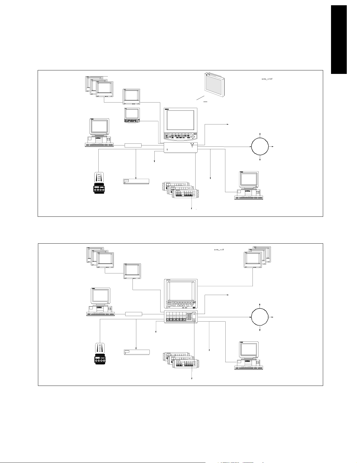
Remote Displays
Remote Displays
(color or monochrome)
(color or monochrome)
8 Channel
8 Channel
RS232 Interface
RS232 Interface
to the Ohmeda
7800/7810/7900 Ventilator
7800/7810/7900 Ventilator
to the Ohmeda
(Flatscreen)
(Flatscreen)
Analog Output Interface
Analog Output Interface
RS232 Interface
RS232 Interface
(standard)
Independent
Independent
(standard)
Anesthetic Gas Module
Anesthetic Gas Module
Display
Display
(color and monochrome)
Independent Display
Digital Recorder Interface
(4-Channel Reco rder M1117A )
(4-Channel Recorder M1117A)
M1026A
M1026A
(CRT)
(CRT)
Independent Display
Independent Display
Interface
Interface
(color and monochrome)
(4 or 8 channels in color)
Interface
(color only)
(4 or 8 channels in color)
Satellite Racks
Satellite Racks
Independent Display
Interface
(color only)
Digital Recorder Interface
Main Display
Main Display
M1046B
M1046B
(8 or 6 slots)
(8 or 6 slots)
Or XGA Display
Or XGA Display
Defibrillator Sync.
Defibrillator Sync.
Network Interface
Monitoring Network Interface
Printer
Printer
“VueLink” M1032A
“VueLink” M1032A
(link to external devices)
(link to external devices)
i-Stat
i-Stat
Central
Central
Data Station
Data Station
2nd RS232 Interface
2nd RS232 Interface
PC
PC
Gateway
Gateway
Monitoring
Monitoring
Network
Network
Concepts
Introducing the CMS
Remote Displays
(color or monochrome)
8 Channel
RS232 Interface
to the Ohmeda
7800/7810/7900 Ventilator
Analog Output
PC
Independent
Display
Interface
RS232 Interface
(standard)
Anesthetic Gas Module
Independent Display
Interface
(color or monochrome)
Digital Recorder Interfac e
(4-Channel Recorder M1117A)
M1026A
Main Display
(6 channels in monochrome,
4 or 8 channels in color)
M1046A with Integral
Rack
(8 slots)
Satellite Racks
(8 or 6 slots)
Defibrillator Sync.
Monitoring Network Interface
Printer
“VueLink” M1032A
(link to external devices)
CMS (Flatscreen) System Overview
Remote Displays
(color or monochrome)
i-Stat
Central Data Station
Gateway
Monitoring
Network
2nd RS232 Interface
PC
M1165A/66A/75A/76A
CMS (CRT) System Overview
M1167A/77A
Figure 1-1 Philips CMS Patient Monitoring System
Introducing the CMS 1-3
Page 20
Main Display Module
I
duci
he CMS
ng t
ntro
Main Display Module
The Main Display Module of the CMS can be a 10.4" Color flatscreen, a 14" CRT, or an offthe-shelf XGA-compatible display. CRT display-based CMSs can use either a Color CRT
Display (M1094B or M1094A) or a Monochrome CRT Display (M1092A) as the Main
Display Module. Slave CRT Displays can be daisy-chained from any other CRT displays.
Additional independent displays, CRTs and flatscreens can be connected but they need
their own display controller in the Computer Module allowing them to show different
information than the main display under software control.
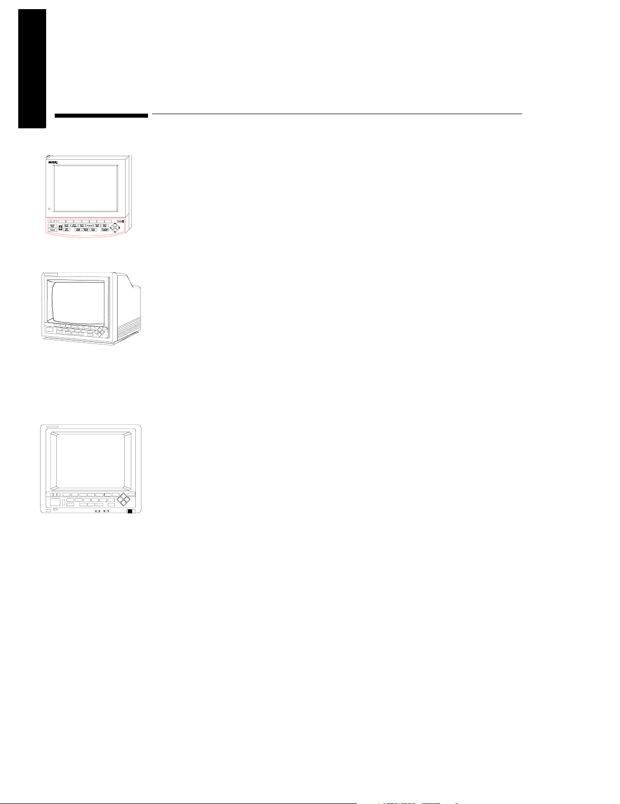
Flatscreen
Main Display
The main display (flatscreen or CRT) contains a consistent arrangement of indicators and
keys on the Control Panel (human interface). There are two versions of the Control Panel
and Handheld Keypad: Standard and Classic. The Classic is no longer available. The
Standard Control Panel is available in supported local languages. Slave and independent
displays have no Control Panel fitted.
CRT Main Display
Front Pan e l of
Display Module
Objective
In order to meet this section’s goals, you should be able to:
• Identify the controls and connectors of the Display Module.
• Be familiar with the function of the controls and connectors of the Display Module.
Concepts
With the exception of Options H03/4, the Main Display Module can be either a flatscreen
or CRT with a Control Panel on the front panel or bezel. The bezel contains the Control
Panel, as well as the main power switch and the adjustments for brightness and contrast.
The rear of the display is referred to as the rear panel and contains the rest of the
adjustment controls and all of the connectors. The HIL Connector on the CRT Display is
on the lower right-hand corner of the front panel.
Note: With Options H03/4 the Main Display Module is an XGA-compatible display and the
Control Panel is the Handheld Keypad with External Alarm Device.
1-4 Introducing the CMS
Page 21

Main Display Module
Front Panel The plastic bezel on the front of the display that contains controls
and connectors, including the Control Panel and display
adjustments.
Standard
Control Panel
Classic Control
Panel
The hardkeys, softkeys and alarm indicators of the Standard human
interface (Release E or later). Includes Airway Gas/Ventilation key.
The hardkeys, softkeys and alarm indicators of the Classic human
interface. Available with and without the SUSPEND key (see Parts
List). Includes HELP key. The Classic Control Panel is not supported
from CMS Release B.0.
HIL Connector The Human Interface Link (HIL) Connector on the Main Display is
used to attach the Handheld Keypad and uses Philips HIL protocol to
transfer data to the system. The HIL Connector on the CRT Display,
which is on the lower right-hand corner of the front panel, can be
covered with a plastic insert when not in use.
Softkeys These are blank single-press keys used as selection controls to enter
Task Windows. They correspond to the softkey labels displayed
above them on the screen.
Hardkeys These are single-press keys with labels used as selection controls.
Typically, a hardkey accesses the Selection Window of its label.
Introducing the CMS
Rear Panel The panel on the rear of the display that contains display controls
and connectors for power, HIL and video.
Introducing the CMS 1-5
Page 22
Main Display Module
I
duci
he CMS
ng t
ntro
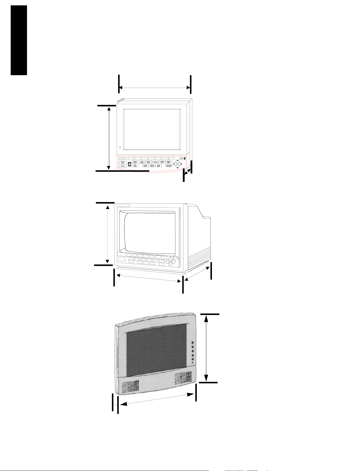
302mm
(11.9")
280mm
(11")
337mm
(13.5")
370mm
(14.6")
Flatscreen Main Display Module
63mm
(2.5")
CRT Main Display Module
451mm
(17.8")
333,5mm
(13.2")
XGA Flatscreen Display Module
408mm
76,7mm
(16.1")
(3.2")
1-6 Introducing the CMS
Page 23
Main Display Module
Figure 1-2 Display Modules with Dimensions
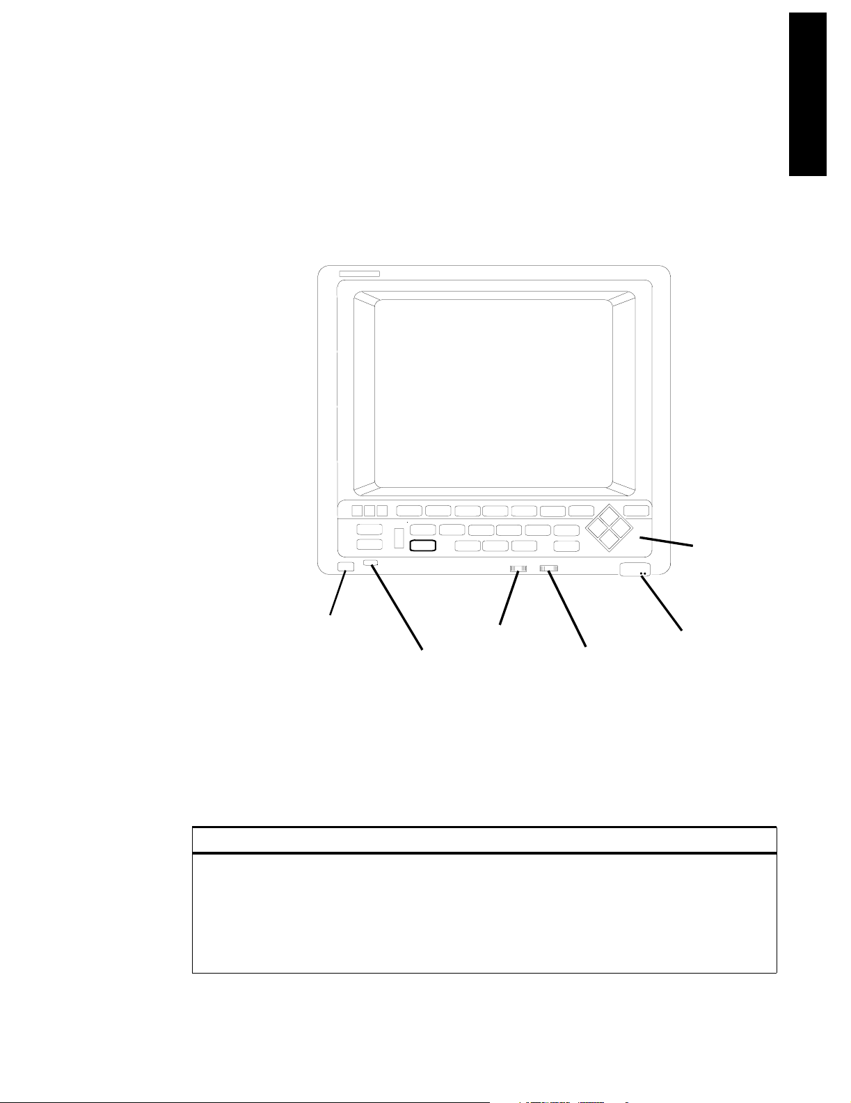
Front Panel Controls and Connectors – CRT Display
The controls and connectors on the front panel of the Display Module are shown below:
mar2bb.mif
CONFIRM
SILENCE /
SUSPEND
RESET
ALARMS/
VOLUME
SCREEN
OTHER
MONITOR
PATIENTS
MAIN
CHANGE
SETUP
REALTIME
SCEEN
RECORD
PROCEDURES
DELAYED
RECORD
TRENDS/
MODULE
CALC
SETUP
AIRWAYS GASES/
VENTILATION
HIL
Control
Panel
(6)
Introducing the CMS
ON/OFF Switch
(1)
Power ON
Indicator
(2)
Figure 1-3 The Display Module Front Panel
Contrast
Control
(3)
Brightness
Control
(4)
Human
Interface Link
Connector
(5)
Table 1-1 Display Module Front Panel Controls and Connectors
Controls Function
1 ON/OFF Switch Used to turn the display On/ Off. This is the only power switch for the
system and it must be pushed in for power ON.
2 Power ON indicator Green LED, which is lit when the display is switched ON.
3 Contrast Control Rotary control, used to vary the contrast of the display.
4 Brightness Control Rotary control, used to vary the brightness of the display.
Introducing the CMS 1-7
Page 24
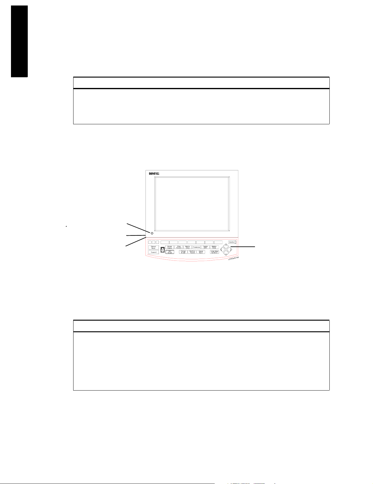
Main Display Module
I
duci
he CMS
ng t
ntro
Table 1-1 Display Module Front Panel Controls and Connectors
Controls Function
5 HIL Connector Human Interface Link (HIL) connector is used to connect the
Handheld Keypad. This connector may be covered by a plastic insert
when not in use.
6 Control Panel User interface of the Display Module.
Front Panel Controls and Connectors – Flatscreen Display
The controls on the front panel of the Flatscreen Display are shown below:
3
2
1
Figure 1-4 The Flatscreen Display Front Panel
4
Table 1-2 Flatscreen Display Front Panel Controls and Connectors
Controls Function
1 ON/OFF Switch Used to turn the display On/Off and used as the remote switch for
2 Brightness Control Rotary control, used to vary the brightness of the display.
3 Power ON indicator Green LED which is lit when the display is switched ON.
4 Control Panel User interface of the Display Module.
either the M1047A Remote Power Supply or the M1046B Computer
Module integral power supply.
1-8 Introducing the CMS
Page 25
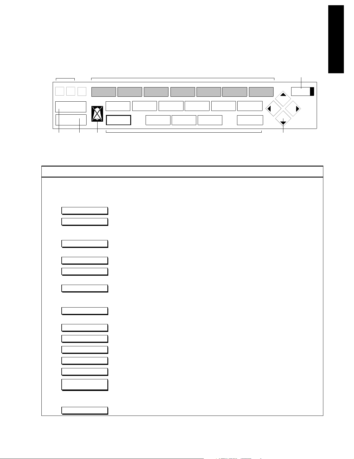
Main Display Module
Introducing the CMS
Alarm Indicators (2)
Silence/
Reset
Suspend
(3) (4)
(5)
Alarms/
Volume
Main
Screen
Other
Patients
Change
Screen
Softkeys (1)
50/140
Monitor
Setup
Realtime
Record
Procedures
Hardkeys (6-16)
Delayed
Record
Trends/
Calcs
Module
Setup
Airway Gases
Ventilation
(18)
Confirm
wclo12a7.tif
Arrow Keys (17)
Table 1-3 Standard Control Panel Controls
Controls Function
1 Softkey Selection controls for the softkey labels displayed above them on the screen. Softkeys
2 Alarm Indicators Indicates the color of the alarm: RED and YELLOW.
3 Used to silence an alarm and, if the cause has been eliminated, reset it.
4 Used to switch all alarms on/off.
Silence/ Reset
Suspend
5 Alarms Off Indicator Indicates that all alarms have been shut off.
bring up Task Windows.
6 Used to turn all alarms off/on and individual alarms on/off, adjust alarm limits and volume,
Alarms/Volume
limits, show the alarm messages and go to standby mode.
7 Used to view data and alarms between beds.
8 Used to change settings such as screen displays and patient type, setup OxyCRG (Standard
Other Patients
Monitor Setup
CMS only) and recording and make general configuration changes.
9 Used to perform Cardiac Output and Wedge Pressure measurements, make ST segment
Procedures
monitoring adjustments, review ST wave segments, admit and discharge patients, or end
particular patient case and transfer patient data.
10 Used to view data in graphs and tables, do physiological calculations in graphs, print
Trends Calc
reports and mark events to view in graphs.
11 Used to set up and change settings for all modules that are plugged into the CMS.
12 Used to return the standard monitoring screen.
13 Used to freeze waves on the screen and change between screen layouts.
14 Used to start a realtime preset recording or a realtime selected recording.
15 Used to start a delayed recording.
16 Used to measure airway gases or show ventilator data.
Module Setup
Main Screen
Change Screen
Realtime Record
Delayed Record
Airway Gases
Ventilation
17 Arrow Keys Used to move highlighting and make selections in the Task Windows - only active when lit.
18 Used to confirm that the user input is correct - only active when lit.
Confirm
Introducing the CMS 1-9
Page 26
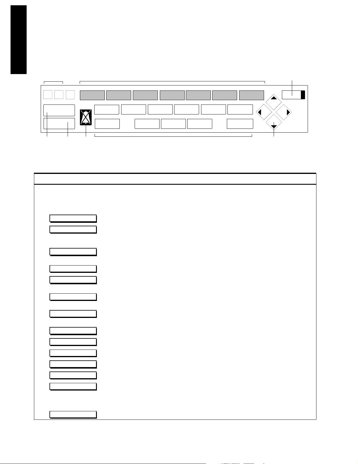
Main Display Module
I
duci
he CMS
ng t
ntro
Alarm Indicators (2)
Silence/
Reset
Suspend
(3) (4)
Alarms Overview
Standard
Display
(5)
Screen
Softkeys (1)
50/140
Instrument Monitoring Patient
Config
Hardkeys (6-16)
MarkCapture
Event
Procedures
Data
Record
(18)
Confirm
Parameters
Help
wclo12a7.tif
Arrow Keys (17)
Table 1-4 Classic Control Panel Controls
Controls Function
1 Softkey Selection controls for the softkey labels displayed above them on the screen. Softkeys
bring up Task Windows.
2 Alarm Indicators Indicates the color of the alarm: RED and YELLOW.
3 Used to silence an alarm and, if the cause has been eliminated, reset it.
4 used to switch all alarms on/off.
Silence/ Reset
Suspend
5 Alarms Off Indicator Indicates that all alarms have been shut off.
6 Used to turn all alarms off/on and individual alarms on/off, adjust alarm limits, show the
Alarms
alarm messages and go to standby mode.
7 Used to view data and alarms between beds.
8 Used to setup OxyCRG and recording, change between main screens and combinations of
Overview
Instrument Config
OxyCRG or Split Screen Trending, or to make general configuration changes.
9 Used to perform Cardiac Output and Wedge Pressure measurements, review ST wave
Monitoring Procedures
segments, admit and discharge patients, or transfer patient data.
10 Used to view data in graphs and tables, do physiological calculations in graphs and print
Patient Data
reports.
11 Used to setup and change settings for all modules that are plugged into the CMS.
12 Used to return to the standard monitoring screen.
13 Used to freeze the screen.
14 Used to display softkeys to mark events you can view in graphs and softkeys for cal signals.
15 Used to display softkeys to make delayed recordings or realtime recordings.
16 Used to provide information about tasks. NOTE: HELP below softkey label on screen
Parameters
Standard Display
Capture Screen
Mark Event
Record
Help
points to item you will get help for.
17 Arrow Keys Used to move highlighting and make selections in the Task Windows - only active when lit.
18 Used to confirm that the user input is correct - only active when lit.
Confirm
1-10 Introducing the CMS
Page 27
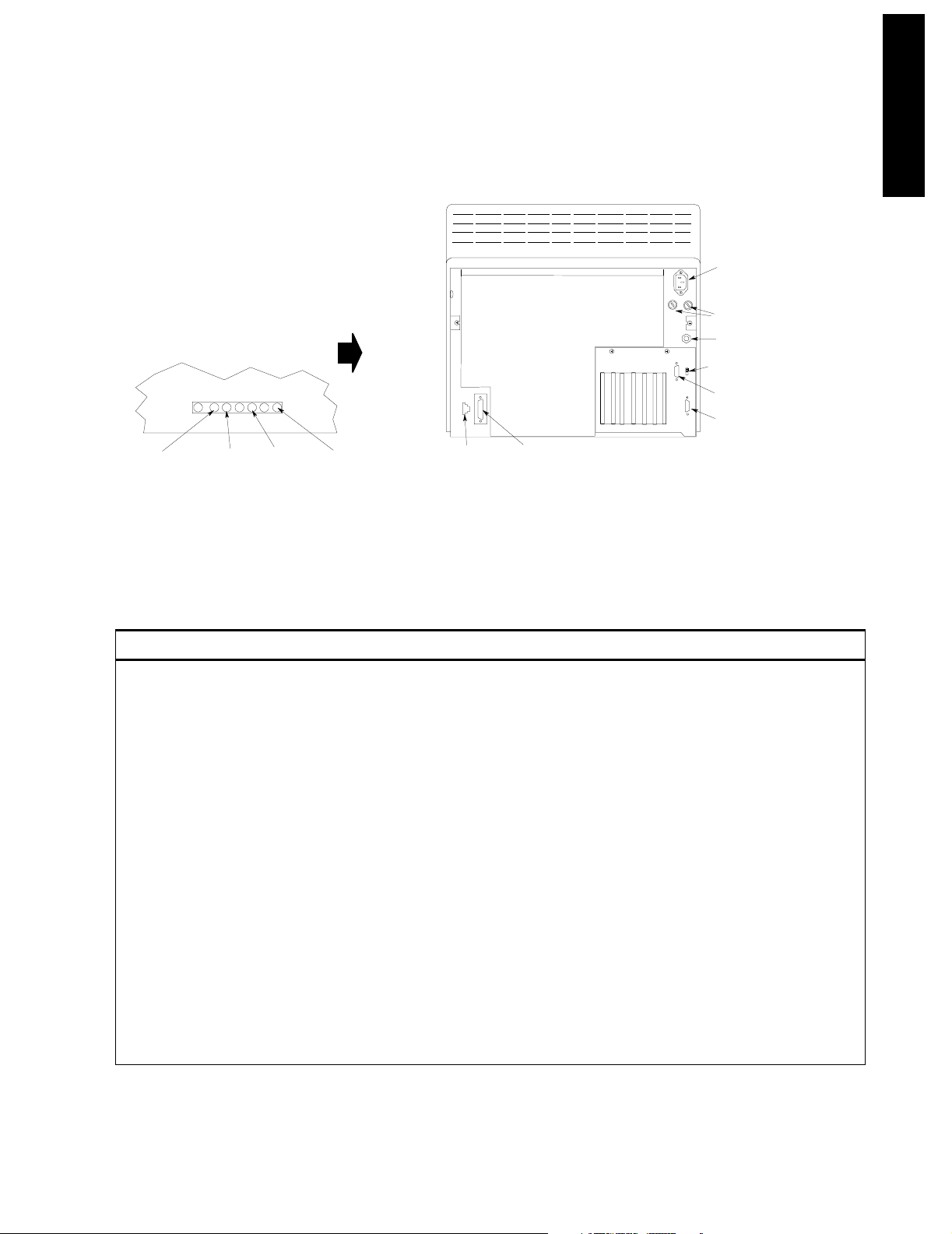
Main Display Module
)
Rear Panel Controls and Connectors
LOCATED ON RIGHT SIDE OF DISPLAY
EAST WEST
(5)
V SHIFT
(3)
H AMP
(4)
Figure 1-5 Rear Panel of the M1094B Display Module
Table 1-5 Main CRT Display Rear Panel Control and Connectors
V AMP
(2)
Human Interface
Link Connector
(11)
System Power
Connector
(8)
Local Power Connector
Fuses
Equipotential Grounding
Terminal (12)
Video Termination Sw it c h ( 1
Video Out Connector (10)
Video In Connector (9)
(7)
(6)
rear1
Introducing the CMS
Controls and Connectors Function
1 Video Termination Switch Used to terminate the video signal at this display. This must be switched to the
75Ω position if only a main display is used. When a remote display is connected,
the video termination switch on the main display must be switched to High Imp.
2 V AMP Vertical amplitude control, used to adjust the height of the displayed video.
3 V SHIFT Vertical shift control, used to adjust the vertical position of the displayed video.
4 H AMP Horizontal amplitude control, used to adjust the width of the displayed video.
5 EAST WEST Used to adjust the pin-cushion effect of the displayed video.
6 Fuse Holders Two fuse holders for the line protection fuses, one for the higher operating voltage
range and one for the lower operating voltage range.
7 Local Power Connector 3-pin connector, used to input the local line voltage.
8 System Power Connector 15-pin “D” type connector, used to output the 60V dc supply to a similar connector
on the DC/DC converter in the rear of the Computer Module.
9 Video In Connector 9-pin “D” type connector, used to input the video signal to be displayed from the
display controller in the Computer Module (DSPC for monochrome or CDSPCVideo for color).
10 Video Out Connector 9-pin “D” type connector, used to output the video signal to be displayed on a slave
display.
Introducing the CMS 1-11
Page 28
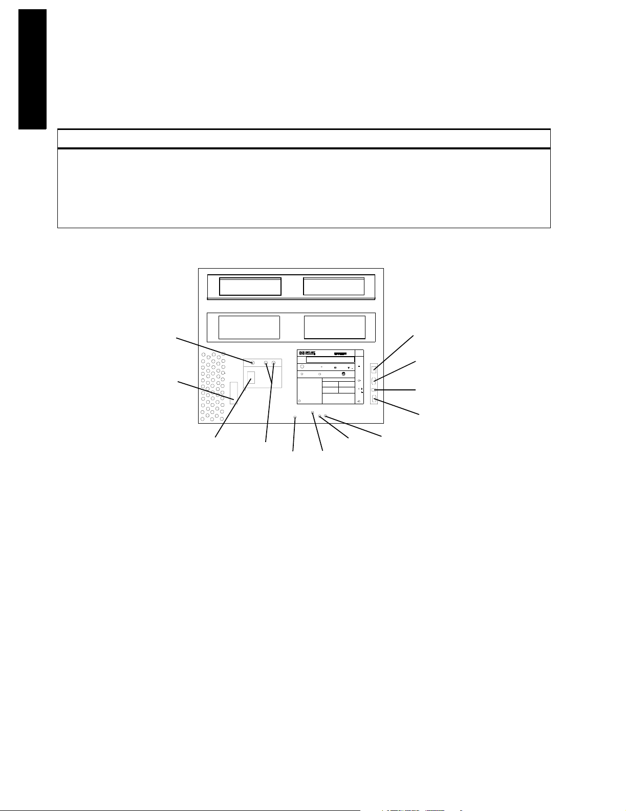
Main Display Module
I
duci
he CMS
ng t
ntro
Table 1-5 Main CRT Display Rear Panel Control and Connectors
Controls and Connectors Function
11 Human Interface Link
Connector
12 Equipotential Grounding
Termi na l
Equipotential
Grounding Terminal
(12)
System Power
Connector
(8)
Human Interface Link (HIL) connector, used to output the information from the
Control Panel and the Handheld Keypad to the Utility CPU function card in the
Computer Module.
Grounding stud connector, used to connect the Display Module to an equipotential
grounding system, if required. The overall system is normally grounded at the
grounding terminal on the Computer Module.
90 x 120
Human Interface Link
Connector
(11)
Local Power
Connector
(7)
Fuses
(6)
V AMP
(2)
M1092A
Limited
MEDICAL
U
EQUIPMENT
L
x x x x x x
N
V SHIFT
R
S
A
LR 49394
C
FI
CAUTION ATTENTION
VORSICHT
(3)
STANDARD NORME
C22 NO 12b
CATEGORIE
RISA
DE RISQUES
CLASS
HIL
tuv
S
G
871-8
VIDEO
CUIDADO
75
HIGH
IMP.
VIDEO
H AMP
(4)
U
U
U
U
EAST WEST
Video Out
Connector
Video Termination
Video IN
Connector
(5)
(10)
Switch
(1)
(9)
mar5b
Figure 1-6 Rear Panel of the M1092A & M1094A Main Display Modules
1-12 Introducing the CMS
Page 29
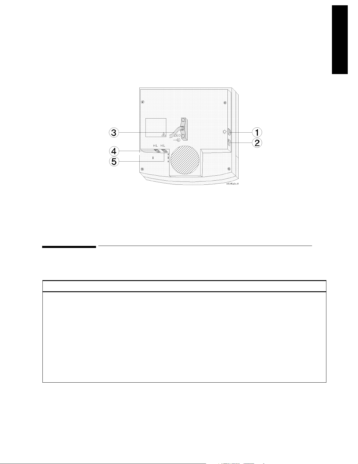
Slave Display Module
Introducing the CMS
Figure 1-7 Rear Panel of the M1095A Main Display Module
Slave Display Module
Table 1-6 Flatscreen Rear Panel Controls and Connectors
Controls and Connectors Function
1 Brightness Control Adjusts the brightness of the display.
2 ON/OFF Switch Used to turn the display On/Off and used as the remote switch for either the
3 Combined Video In / Power
Connector
4 Human Interface Link Connector InThis Human Interface Link (HIL) connector is used to connect the handheld
5 Human Interface Link Connector
Out
M1047A Remote Power Supply or the M1046B Computer Module integral
power supply.
This is a male SCSI connector with 25 pin pairs used to input the video signal
and the 60 V DC line voltage.
keypad.
This Human Interface Link (HIL) connector is used to output the information
from the handheld keypad and control panel to the Utility CPU function card in
the computer module.
Introducing the CMS 1-13
Page 30
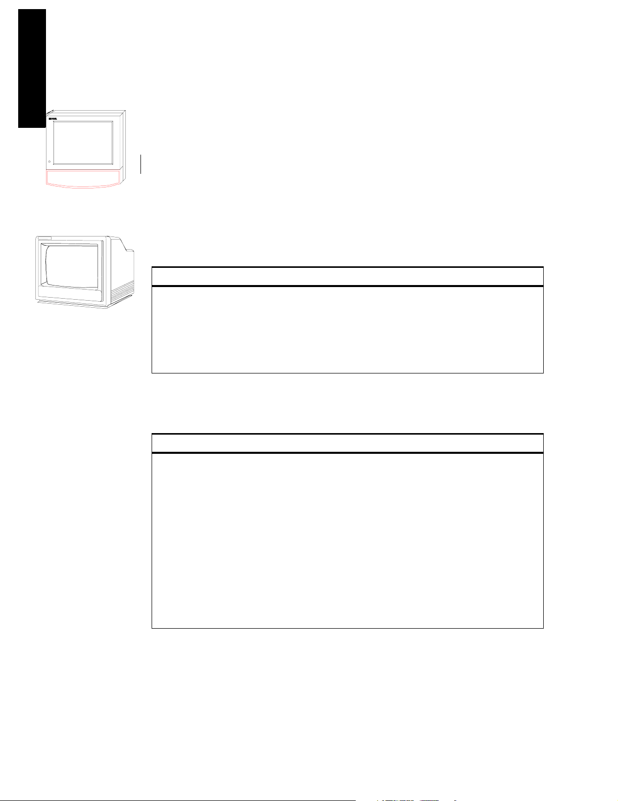
Slave Display Module
I
duci
he CMS
ng t
ntro
Independent
Flatscreen Display
without Control Panel
Independent / Slave
CRT Display
without Control Panel
The CMS supports additional displays as either CRT Slave or Flatscreen and CRT
Independent Display Modules. CRT Slave Displays connect directly to any CRT and
display the same information as the CRT they are connected to. Independent Displays
have their own display controller in the Computer Module and may display different
information than the Main Display under software control. Slave and Independent
Displays are intended as a visual reference and do not have a Control Panel. The
information on the 21" slave display can be found in its accompanying manual. See also
the Appendix, “Remote 21" Displays”.
14" Slave Display Front Panel Controls
Table 1-7 Slave Display Front Panel Controls
Controls Function
ON/OFF Switch Push button switch, used to turn the slave display ON and OFF.
This must be pushed in for power ON.
Power ON indicator Green LED which is lit when the display is switched ON.
Brightness Control Rotary control, used to vary the brightness of the display.
Contrast Control Rotary control, used to vary the contrast of the display.
14" Slave Display Rear Panel Controls and Connectors
Table 1-8 Slave Display Rear Panel Controls and Connectors
Controls and Connectors Function
Video Termination Switch Push button switch, used to terminate the video signal at this
display. This switch must be ON (in) or 75
the last in the chain. Otherwise the switch must be OFF (out) or
High Imp.
Fuse Holders Holders for the line protection fuses.
Local Power Connector 3-pin connector, used to input the local line voltage.
Video In Connector Male 9-pin “D” type connector, used to input the video signal to
be displayed from the main Display Module.
Video Out Connector 9-pin “D” type connector, used to output the video signal to be
Equipotential Grounding
Ter mi na l
displayed on another Slave Display Module.
Grounding stud connector, used to connect the system to an
equipotential grounding system.
Ω if the slave display is
1-14 Introducing the CMS
Page 31

Front Panel
Slave Display Module
Introducing the CMS
BRIGHTNESS CONTROL
POWER ON INDICATOR
ON/OFF SWITCH
Rear Panel of M1092A and M1094A
Rear Panel of M1094B
CONTRAST CONTROL
LOCAL POWER CONNECTOR
FUSES
EQUIPOTENTIAL GROUNDING
TERMINAL
VIDEO TERMINATION SWITCH
VIDEO OUT CONNECTOR
VIDEO IN CONNECTOR
FUSES
EQUIPOTENTIAL
GROUNDING TERMINAL
LOCAL POWER
CONNECTOR
VIDEO OUT CONNECTOR
90 x 120
M1092A
Limited
MEDICAL
U
R
EQUIPMENT
L
S
A
LR 49394
x x x x x x
C
N
FI
STANDARD NORME
C22 NO 12b
CATEGORIE
RISA
DE RISQUES
CLASS
CAUTION ATTENTION
CUIDADO
VORSICHT
HIL
tuv
S
G
871-8
VIDEO
75
HIGH
IMP.
VIDEO
VIDEO TERMINATION SWITCH
U
U
U
U
VIDEO IN CONNECTOR
Figure 1-8 Slave Display Controls and Connectors
Introducing the CMS 1-15
mar5b
Page 32

Handheld Keypad
I
duci
he CMS
ng t
ntro
Handheld Keypad
Handheld Keypad
The Handheld Keypad of the CMS is an external device used for inputting patient
information and working with the drug calculator that is a part of the monitor. There are
three released versions of the Handheld Keypad. The first release (M1106A) is called the
Classic Handheld Keypad. The second release (M1106B) added the SUSPEND hardkey to
the Classic Handheld Keypad. The current release (M1106C) is called the Standard
Handheld Keypad and it contains the same number of keys as the M1106B but improves
on the hardkey key labels and functionality to make them more user-friendly.
Note: Only the Standard Handheld Keypad (M1106C) is supported with Release B.0. The
Classic Handheld Keypad (M1106A or M1106B) is not supported for use with Release B.0.
Objective
In order to meet this section’s goals, you should be able to:
• Identify the controls and connectors of the Handheld Keypad.
• Be familiar with the function of the controls and connectors of the Handheld Keypad.
Concepts
The Handheld Keypad provides remote access to all monitoring tasks. There are 55
domed buttons on the membrane keyboard which provides a fluid seal to make cleaning
easier. A coiled cable is used to connect the keypad to the master or main display, or to
the External Alarm Device.
Membrane
Keypad
Standard
Control Panel
Classic Control
Panel
HIL Connector Human Interface Link (HIL) Connector is used to connect the
Alphanumeric
Keys
1-16 Introducing the CMS
The plastic bezel on the front of the Handheld Keypad that contains
the controls and connectors, including the Control Panel and
alphanumeric keypad.
The hardkeys, softkeys and alarm indicators of the Standard user
interface (Release E or later).
The hardkeys, softkeys and alarm indicators of the Classic user
interface. Available with and without the SUSPEND key (see Parts
List).
Handheld Keypad to the Main Display, or to the External Alarm
Device. Information is transferred to the system using Philips HIL
protocol.
These are single-press keys used to input patient information and
drug calculations into the monitor.
Page 33

Handheld Keypad
210/140
Handheld Keypad Membrane Keyboard
All of the softkeys and hardkeys on the Display Module are also found on the Handheld
Keypad. See Table 1-3 and Table 1-4 and for descriptions of these keys. In addition, the
Philips Handheld Keypad has keys for alphanumeric data entry.
Softkeys
Airway Gases/
Ventilation
Confirm
S
.,
keypada1
Standard
Hardkeys
Confirm Key
Arrow Keys
Alphanumeric
Keys
Handheld Keypad
Connector
Silence/Reset
Key
Suspend Key
Space Key
Shift Key
M1106C
Silence/
Reset
Suspend
Space
Space
Shift
Alarms/ Other
Volume
Main
Screen
Patients
Change
Screen
C
B
A
7
89
FGH
4
56
K
LM
1
T
0
3
2
U
V
.
Monito r
Setup
Realtime Delayed
Record Record
D
.
.
-
I
X
N
-
W
+
Procedures
E
J
O
PQR
X
Y
Trends/ Module
Calcs Setup
Z
Introducing the CMS
Figure 1-9 Handheld Keypad Controls and Connector
Table 1-9 Handheld Keypad Standard Control Panel
Standard Control Panel Function
Space
Shift
Alphabet Characters (A - Z) These characters can be entered only in alpha mode (when the LED on the Shift key is lit).
Punctuation Marks (, .) The punctuation marks can be entered only in numeric mode (when LED on Shift key is
Numeric Characters (0 - 9) These characters can be entered only in numeric mode (when LED on Shift key is not lit).
Arithmetic Operators (+ - * /) These characters can be entered only in numeric mode (when LED on Shift key is not lit).
Decimal Point (.) The decimal point can be entered only in numeric mode (when LED on Shift key is not lit).
Handheld Keypad Connector
(Philips-HIL)
Used to enter spaces between numbers or letters
Used to switch between alpha and numeric mode. The LED is lit when keypad is in alpha
mode.
not lit).
This connector fits into the Philips-HIL connector on the lower right corner of the Display
Module.
Introducing the CMS 1-17
Page 34

Handheld Keypad
I
duci
he CMS
ng t
ntro
Handheld Keypad Rear Cover
The rear cover of the Handheld Keypad contains a magnet to secure it to the keypad
mounting bracket or to the External Alarm Device.
External Alarm Device M1109A
Yellow Alarm
Red Alarm
indicator
indicator
Alarms-Off indicator
Green LED
On-Off Switch
Keypad
Mounting
Bracket
eadevice.hpg
Remote On-Off
to Computer Module
HIL to Computer Module
HIL to Keypad
Universal Mounting Clamp
The External Alarm Device, for use with off-the-shelf XGA displays, provides visual and
audible alarm indicators. It has a bracket to hold the Handheld Keypad. It also provides an
on/off switch to remotely control the M1046B CMS Computer Module.
CAUTION Always locate this device in such a way that the speaker at the rear and the lights
on the front are not blocked.
1-18 Introducing the CMS
Page 35

Computer Module
Computer Module (M1046A)
with integral rack
Computer Module
Introducing the CMS
The Computer Module of the CMS contains the hardware and software for the processing
functions of the monitor. It can be thought of as the heart of the system. It distributes all
the power, clocks and data for the whole system. There are several released
configurations for the function cards of the Computer Module. Your configuration will
depend on the version of software and hardware your monitor is running and the options
it is supporting. All of the function cards connect to the Computer Module backplane,
whether from the front or from the rear of the unit. Function cards that require external
connections are located in the rear of the Computer Module.
Objective
In order to meet this section’s goals, you should be able to:
Computer Modu le (M1046A)
with integral blank rack
Computer Module (M1046B)
with integral power supply
• Identify the connectors of the Computer Module
• Be familiar with the functions of the Computer Module.
Concepts
The Computer Module of CMS is not fitted with any controls, just connectors. The front of
the M1046A Computer Module can be mounted with an integral plug-in module rack or a
blank rack. Each rack contains an internal rack connector used to output information
from the rack to the Rack Interface function card placed in slot 18 of the computer
module. All of the other connections for the Computer Module are in the rear and will
depend on the options and revision of your monitor.
Integral Plug-in
Module Rack
Blank Rack The blank rack is used to cover the front of the Computer Module
Integral Power
Supply
The integral plug-in module rack fits in the front of the Computer
Module (M1046A) and holds plug-in modules. It contains a rear
connector that is used to output information from the rack to the
Computer Module.
(M1046A) when a satellite plug-in module rack is being used. It
contains a rear connector that is used to output information from the
rack to the Computer Module.
The integral power supply is used to power the Computer Module
(M1046B), a satellite plug-in module rack, and a flatscreen main
display without the need for a Remote Power Supply. It connects to
the REMOTE_SWITCH card in the Computer Module to allow the
flatscreen display to control the Computer Module power.
Backplane The backplane of the Computer Module contains the connections for
the front and rear function cards.
Introducing the CMS 1-19
Page 36

Computer Module
I
duci
he CMS
s
ng t
ntro
CPC Flash Port This port is located on the Configurable Processor Card (CPC) in slot 12
and is the connector for the CPC Programming Tool.
M1046A with Integral Blank Rack
370mm
(14.6")
451mm
(17.8")
156mm
(6.2")
M1046A with Integral Rack & Parameter Module
156mm
(6.2")
370mm
(14.6")
491mm
(19.3")
M1046B with Integral Power Supply
156mm
(6.2")
370mm
(14.6")
451mm
(17.8")
Figure 1-10 Computer Module Dimensions
Brief Functional Overview
The Philips CMS Patient Monitoring System is a loosely coupled multi-processor system
containing several CPU cards. They can communicate with each other but do not have access
to each other’s memory. They can only exchange information in the form of messages.
The backplane can be functionally sectioned into three logical parts or buses, the Message
Passing Bus, the Local Bus and the Utility Bus.
Message Passing
Bus
Local Bus This is the local communication system. It is a buffered processor bus
This is the global communication bus for the system, and is used for
communications between CPU cards as well as to intelligent interface
cards (for example, RS232 Interface and the display controllers). This
bus appears on all the connectors.
that allows access to local memory cards, SRAM and EPROM that
contain software for the exclusive use of the master processor.
The local bus appears on all the connectors on the backplane but is
interrupted to connect groups of connectors into local clusters.
1-20 Introducing the CMS
Page 37

Computer Module
Utility Bus This includes functions required by the whole system; for example,
power and clock signal distribution. This bus appears on all the
connectors.
Local Clusters The local bus is connected to all the connectors in the backplane but
it is interrupted to form clusters that share a connection to the same
local bus. There are 10 local clusters in the backplane with varying
numbers of connectors.
Delivered Configurations
The versions and models described by this guide are listed as follows (models indicated
by asterisk were discontinued. “(S)” indicates a non-US-model):
CMS: M1165A/66A/67A Models 54(S)*, 56(S), 64(S), 66(S) and 68(S)
CMS: M1175A/76A/77A Models 54*, 56, 66 and 68
ACMS: M1165A/66A/67A Models 74(S)*, 76(S), 84(S), 86(S) and 88(S)
ACMS: M1175A/76A/77A Models 74*, 76, 86 and 88
NCMS: M1165A/66A/67A Models 34(S)*, 36(S)*, 44(S), 46(S)* and 48(S)
NCMS: M1175A/76A/77A Models 34*, 36*, 46* and 48
Introducing the CMS
The CMS products M1167A and M1177A use the Computer Module (M1046B).
There are three types of Application CPU Cards used in the Systems: M1054 (10 MHz) and
M1051 (15 MHz) and M1053 (40 MHz CPC Card).
Function Card placement in the Backplane is dependent upon the variant of the System
and the type of Application CPU Cards. Card placements for all variants of the CMS are
illustrated in Table 1-10 Function Card Placement on page 1-23
Function Cards of the Computer Module
The function cards are interconnected by the backplane within the Computer Module;
refer to the Concepts Guide for a full functional description of the backplane and its
theory of operation. The function cards are mounted on both sides of the backplane and
may be located either in the front of the Computer Module (even-numbered connectors)
or the rear (odd-numbered connectors). The local clusters of the backplane are colorcoded on the Computer Module, so that they can be easily identified. On the rear of the
backplane, to the left of connector 21, there is a triple-sized gap. This is the only place
where the dc-dc converter can be located.
The newer Computer Module (M1046B) has an integral power supply. As a result these
Computer Modules have additional function cards. These additional cards are described
in Table 1-10 Function Card Placement on page 1-23.
Introducing the CMS 1-21
Page 38

Computer Module
I
duci
he CMS
ng t
ntro
Function Card Placement
Function Card Placement in the backplane of the Philips monitor is dependent upon the
following (“(S)” indicates the non-US-models):
1.The monitor model:
•CMS: Models 54 (S), 56 (S), 64 (S), 66 (S), 68 (S)
•ACMS: Models 74 (S), 76 (S), 84 (S), 86 (S), 88 (S)
•NCMS: Models 36 (S), 44 (S), 46 (S), 48 (S)
2.Type of processor cards used:
•10 MHz CPU cards M1054-66501
•15 MHz CPU cards M1051-66501
•40 MHz CPC card M1053-66515
3.Type and combination of display controllers used:
•M1066-66501 DSPC (Monochrome)
•M1066-66531 DSPC (Monochrome)
•M1066-66543 DSPC (Monochrome with integrated DSPC-lang)
•M1072-66521 CDSPC-CTRL (Color) together with M1072-66501 CDSPC-VIDEO
•M1072-66531 CDSPC (Color)
•M1072-66543 (Color with integrated DSPC-lang)
•M1074-66501 DSPC-FLAT (Flatscreen color)
•M1074-66502 DSPC-FLAT (Flatscreen color)
•M1074-66503 DSPC-FLAT (Flatscreen Color with integrated DSPC-lang)
•M1075-66503 XGA DSPC (XGA with integrated DSPC-lang)
1-22 Introducing the CMS
Page 39

Computer Module
200 x 90
Using 15MHz Application CPUs
Introducing the CMS
Front Slots
2
Gray
4
6
Blue
8
10
Green
12
14
16
18
Blue Strip s
20
22
Green Strips
24
Use the following tables to determine the location of the function cards for your system.
Table 1-10 Function Card Placement
1
3
5
7
9
11
13
15
17
19
21
Rear Slots
Yellow
Red
Red Strips
DC-DC Converter
Using 10MHz Application CPUs
CDSPC_CTRL
EPROM MASTER
EPROM SLAVE
FRONT
BLANK or
CDSPC_CTRL #2
APP_CPU
SRAM
APP_CPU
(Model 68 only)
RACK_IF
APP_CPU
Software Release A
REAR
DSPC or
1
2
4
6
8
10
12
14
16
18
20
22
24
CDSPC_VIDEO
3
APP_CPU
5
DSPC #2 or
7
CDSPC_VID #2
HDLC_IF (If pre se nt )
9
APP_CPU
11
RS232_IF (if present)
13
15
UTIL_CPU
17
SDN_IF (if present)
19
21
DC/DC CONVERTER
EPROM MASTER
FRONT
BLANK or
CDSPC_CTRL
CDSPC_CTRL #2
APP_CPU
(Model 68 only)
SRAM
EPROM SLAVE
RACK_IF
APP_CPU
REAR
DSPC or
1
2
4
6
8
10
12
14
16
18
20
22
24
CDSPC_VIDEO
3
APP_CPU
5
DSPC #2 or
7
CDSPC_VID #2
HDLC_IF (if present)
9
APP_CPU
11
RS232_IF (if present)
13
15
UTIL_CPU
17
SDN_IF (if present)
19
21
DC/DC CONVERTER
Introducing the CMS 1-23
Page 40

Computer Module
I
duci
he CMS
t)
t)
200 x 90
if
ng t
ntro
Table 1-10 Function Card Placement
Software Release B
Using 10MHz Application CPUs
FRONT
DSPC or
BLANK or
CDSPC_CTRL
EPROM MASTER
CDSPC_CTR #2
APP_CPU
SRAM
EPROM SLAVE
APP_CPU
(Model 56 with #C10,
66 with #C10, or 68)
RACK_IF
APP_CPU
2
4
6
8
10
12
14
16
18
20
22
24
1
CDSPC_VIDEO
3
DSPC_KANJI (if presen
APP_CPU
5
DSPC #2 or
7
CDSPC_VID #2
HDLC_IF (If presen
9
APP_CPU
11
RS232_IF (if present)
13
ANALOG_IF (if present)
15
UTIL_CPU
17
SDN_IF (if present)
19
21
DC/DC CONVERTER
Software Release C (15 MHz APP_CPUs)
Models 54(S)/64(S) and Models 56(S)/66(S) without #C26
REAR
DSPC #1 or
1
CDSPC_VID #1
DSPC_LANG
3
(KANJI, TAI or PRC)
15 MHz APP_CPU
5
DSPC #2 or
7
CDSPC_VID #2
HDLC-IF
9
15 MHz APP_CPU
11
RS232_IF
13
ANALOG_IF
15
UTIL_CPU
17
SDN_IF
19
21
DC/DC CONVERTER
BLANK or
CDSPC_CTRL #1
EPROM MASTER
CDSPC_CTRL #2
15 MHz APP_CPU
EPROM SLAVE
RACK_IF
APP_CPU
FRONT
SRAM
2
4
6
8
10
12
14
16
18
20
22
24
REAR
Using 15MHz Application CPUs
FRONT
BLANK or
CDSPC_CTRL
EPROM MASTER
CDSPC_CTR #2
APP_CPU
(Model 68 only)
SRAM
EPROM SLAVE
2
4
6
8
10
12
14
16
RACK_IF
18
20
APP_CPU
22
24
Models 56(S)/66(S) with #C26 and Model 68(S)
FRONT
BLANK or
CDSPC_CTRL #1
EPROM MASTER
CDSPC_CTRL #2
15 MHz APU_CPU
SRAM
EPROM SLAVE
15 MHz APU_CPU
2
4
6
8
10
12
14
16
RACK_IF
18
20
15 MHz APP_CPU
22
24
REAR
DSPC or
1
CDSPC_VIDEO
3
DSPC_KANJI (if present)
APP_CPU
5
DSPC #2 or
7
CDSPC_VID #2
HDLC_IF (if present)
9
APP_CPU
11
RS232_IF (if present)
13
ANALOG_IF (if present)
15
UTIL_CPU
17
SDN_IF (if present)
19
21
DC/DC CONVERTER
REAR
DSPC #1 or
1
CDSPC_VID #1
DSPC_LANG.
3
(KANJI, TAI or PRC)
15 MHz APP_CPU
5
DSPC #2 or
7
CDSPC_VID #2
RS232_IF #1
9
15 MHz APP_CPU
11
RS232_IF #2 or
13
DSPC #3 (only 68(S))
ANALOG_IF
15
UTIL_CPU
17
SDN_IF
19
HDLC_IF
21
DC/DC CONVERTER
Rel_b.m
200 x 90
1-24 Introducing the CMS
Page 41

Computer Module
200 X 90
Table 1-10 Function Card Placement
Upgrade Backplane to Release C (without CPC)
The table below shows the slot locations and quantity of
10 MHz (M1054-66501) and 15 MHz (M1051-66501)
APP_CPUs for those Philips CMS Patient Monitoring System
that have been upgraded from software release A or B with
10 MHz CPU’s exclusively, to software release C without
CPC.
APP_CPU Slot Location and Quantity
A54S/A66S 51, 8, 11, 14, 22
1
A56S,/A66S 5
A56(S)/A66(S) (#C10) 5
A56(S)/A66(S) (#C26) 5
1 This is a 15 MHz CPU.
2 The systems that have been upgraded from
software release B to software release C with
existing C10 will contain a 10 MHz processor in
slot 16. If C10 is added to a Software Release C
monitor, there will not be a 10 MHz processor in
slot 16.
, 8, 11, 14, 22
1
, 8, 11, 14, 162, 22
1
, 8, 11, 14, 161, 22
Rel. C+ to Rel. G 15 MHz APP_CPU Requirements
Model Slot 22 Slot 4
Standard CMS
A68(S) Required Extra card
a
A56(S)/A66(S) Required
A54(S)/A64(S) Extra card Extra card
Anesthesia CMS (from Rel. E
)
ß
A88(S) Required Required
A76(S)/A86(S) (#C25) Required Required
A76(S)/A86(S) without (#C25) Extra card Extra card
A74(S)/A84(S) (#C24) Required Extra card
A74(S)/A84(S) w/o (#C24) Extra card Extra card
Neonatal CMS (from Rel. F)
A36(S)/A46(S)/A48(S) Required Extra card
a. Not required in certain earlier releases.
Extra card
Introducing the CMS
CDSPC_CTRL #1
15 MHz APP_CPU
CDSPC_CTRL #2
15 MHz APP_CPU
Software Release C+ or D (40 MHz CPC)
Models 54(S)/64(S) and Models 56(S)/66(S)
FRONT
BLANK or
40 MHz CPC
RACK_IF
2
*
4
6
8
10
12
14
16
18
20
*
22
24
REAR
DSPC #1 or
1
CDSPC_VID #1
DSPC_LANG
3
(KANJI, TAI or PRC)
5
DSPC #2 or
7
CDSPC_VID #2
RS232_IF
9
11
13
ANALOG_IF
15
UTIL_CPU
17
SDN_IF
19
HDLC_IF
21
DC/DC CONVERTER
FRONT REAR
BLANK or
CDSPC_CTRL #1
15 MHz APP_CPU
CDSPC_CTRL #2
40 MHz CPC
RACK_IF
15MHz APP_CPU
Models 56(S)/66(S) with #C26 and Model 68(S)
DSPC #1 or
1
2
*
4
CDSPC_VID #1
DSPC_LANG
3
(KANJI, TAI or PRC)
5
6
8
7
9
DSPC #2 or
CDSPC_VID #2
RS232_IF #1
10
11
12
14
16
18
20
RS232_IF #2 or
13
DSPC #3 (only 68(S))
ANALOG_IF
15
UTIL_CPU
17
SDN_IF
19
HDLC_IF
21
22
24
* An extra CPU may be left in for future use.
DC/DC CONVERTER
Introducing the CMS 1-25
Page 42

Computer Module
I
duci
he CMS
)
ng t
ntro
Table 1-10 Function Card Placement
Software Release E or E
FRONT
BLANK or
CDSPC_CTRL #1
15 MHz APP_CPU
CDSPC_CTRL #2
40 MHz CPC
RACK_IF
15 MHz APP_CPU
10
12
14
16
18
20
22
24
ß
REAR
DSPC #1 or
1
2
4
6
8
CDSPC_VIDEO #1
DSPC_LANG #1
3
5
DSPC #2 or
7
CDSPC_VIDEO #2
9
RS232_IF #1
(KANJI, TAI or PRC)
15 MHz APP_CPU
CDSPC_CTRL #2
11
ANALOG_IF or
13
DSPC #3 (o nl y model 88)
15
RS232 IF #2
UTIL_CPU
17
SDN_IF
19
HDLC_IF
21
DC/DC CONVERTER
25
40 MHz CPC
100/140
15 MHz APP_CPU
bacone1.tif
* If upgraded (to F) may still have CDSPC_CTRL #1.
Software Release F
FRONT
* BLANK
RACK_IF
2
4
6
8
10
12
14
16
18
20
22
24
1
3
5
7
9
11
13
15
17
19
21
25
REAR
DSPC #1 or
CDSPC #1 or DSPC_FLAT #1
DSPC_LANG #1
(KANJI, TAI or PRC)
DSPC #2 or
CDSPC #2 or DSPC_FL AT #2
RS232_IF #1
ANALOG_IF or
DSPC #3 or DSPC_FLA T #3
or CDSPC #3
RS232 IF #2
UTIL_CPU
SDN_IF
HDLC_IF
DC/DC CONVERTER
(only model 88)
M1046A Computer Module
FRONT
DSPC #1 or
1
* BLANK
15 MHz APP_CPU
CDSPC_CTRL #2
2
4
6
8
10
40 MHz CPC
12
14
100/140
RACK_IF
16
18
20
15 MHz APP_CPU
bacone1.tif
* If upgraded (to G) may still have CDSPC_CTRL #1.
22
24
CDSPC #1 or DSPC_FLAT #1
DSPC_LANG #1
3
5
DSPC #2 or
7
CDSPC #2 or DSPC_FLAT #2
9
RS232_IF #1
11
ANALOG_IF or
DSPC #3 or DSPC_FLAT #3
13
or CDSPC #3
15
RS232 IF #2
UTIL_CPU
17
SDN_IF
19
HDLC_IF
21
DC/DC CONVERTER
25
REAR
(KANJI, TAI or PRC)
Software Release G
15 MHz APP_CPU
CDSPC_CTRL #2
REMOTE_SWITCH
40 MHz CPC
(only model 88)
100/140
15 MHz APP_CPU
AUX_CONNECTOR
bacone1.tif
M1046B Computer Module
FRONT
BLANK
2
4
6
8
10
REAR
DSPC_FLAT_NON_ASIA #1 or
1
DSPC_FLAT_ASIA # 1
3
5
DSPC #2 or
7
CDSPC #2 or DSPC_FLAT #2
9
RS232_IF #1
11
RACK_IF
12
14
16
18
20
ANALOG_IF or
DSPC #3 or DSPC_FLAT #3
13
or CDSPC #3
15
RS232 IF #2
UTIL_CPU
17
SDN_IF
19
HDLC_IF
21
22
24
DC/DC CONVERTER
25
(only model 88
1-26 Introducing the CMS
Page 43

Computer Module
*
d
*
#1
8)
Table 1-10 Function Card Placement
Software Releases A.0 to C.0
M1046A Computer Module
Systems with M1066-66531 or M1066-66543** (DSPC) or
M1072-66531 or M1072 -66543
M1074-66501 ( D SPC_FLAT) or
M1074-66502 (DSPC_FLAT)
FRONT
40 MHz CPC #2
2
4
6
8
REAR
DSPC #1 or
1
CDSPC #1 or DSPC_FLAT #1
DSPC_LANG #1
3
(JAP, PRC, ROC, GRK, POL,
RUS, CZE)
5
DSPC #2 or
7
CDSPC #2 or DSPC_FLAT #2
RS232_IF #1
9
10
40 MHz CPC #1
100/140
RACK_IF
*
15 MHz APP_CPU
For future use – if upgraded
12
14
16
18
20
22
24
11
ANALOG_IF or
DSPC #3 or CDSPC #3
13
or DSPC_FLAT #3(only model 88)
RS232 IF #2
15
UTIL_CPU
17
SDN_IF
19
HDLC_IF
21
DC/DC CONVERTER
25
** with these controllers no DSPC_LANG is require
**
(CDSPC) or
**
M1046B Computer Module
Systems with M1074-66501(DSPC_F LAT) or
FRONT
2
40 MHz CPC #2
4
6
REMOTE
8
10
40 MHz CPC #1
12
14
100/140
RACK_IF
16
18
20
*
15 MHz APP_CPU
*For future use – if upgraded
AUX
22
24
M1074-66502 (D SPC _ FLAT)
REAR
DSPC_FLAT #1or DSPC #1
1
DSPC_LANG #1
(JAP, PRC, ROC, GRK,
3
POL, RUS, CZK)
5
DSPC #2 or CDSPC #2 or
7
DSPC_FLAT #2
RS232_IF #1
9
11
ANALOG_IF or
DSPC #3 or CDSPC #3
13
or DSPC_FLAT #3(only model 88)
RS232 IF #2
15
UTIL_CPU
17
SDN_IF
19
HDLC_IF
21
DC/DC CONVERTER
25
Introducing the CMS
M1046A Computer Module
Systems with M1066-66501 (DSPC) or
CDSPC_CTRL #1
40 MHz CPC #2
CDSPC_CTRL #2
40 MHz CPC #1
100/140
RACK_IF
*
15 MHz APP_CPU
For future use – if upgraded.
M1072-66521 (CDSPC_CTRL) +
M1072-66501 (CDSPC_VIDEO)
FRONT
2
4
6
8
10
12
14
16
18
20
22
24
REAR
DSPC #1 or
1
CDSPC_VIDEO #1
DSPC_LANG
3
5
DSPC #2 or
7
CDSPC_VIDEO #2
RS232_IF #1
9
11
ANALOG_IF or
DSPC #3 (only model 88)
13
RS232 IF #2
15
UTIL_CPU
17
SDN_IF
19
HDLC_IF
21
DC/DC CONVERTER
25
(JAP, PRC, ROC)
M1046B Computer Module
Systems with M1075-66503 (XGA_DSPC) or
M1074-66503 (DSPC_FLAT)
FRONT
2
40 MHz CPC #2
4
6
REMOTE
8
10
40 MHz CPC #1
12
14
100/140
RACK_IF
16
18
20
*
15 MHz APP_CPU
* For future use – if upgraded.
AUX
22
24
REAR
XGA_DSPC #1 or DCPC_FLAT
1
3
5
XGA_DSPC #2 or DSPC #2 or
7
CDSPC#2 or DSPC_FLAT #2
RS232_IF #1
9
11
ANALOG_IF or XGA_DSPC or
DSPC #3 or CDSPC #3
13
or DSPC_FLAT #3(only model 8
RS232 IF #2
15
UTIL_CPU
17
SDN_IF
19
HDLC_IF
21
DC/DC CONVERTER
25
Introducing the CMS 1-27
Page 44

Computer Module
I
duci
he CMS
ng t
ntro
EEPROM Numbers
The part numbers listed in the table below are for cross-reference purposes only. Order a
blank EEPROM (1818-4869) and reprogram it using the relevant upgrade programming
tool.
Table 1-11 CMS EEPROM/CPU Matrix (M1059-85xxx)
Releases A to G
CMS Model XX 10MHz Monitors 15 MHz Monitors 40 MHz CPC Monitors
Rel A Rel B Rel C Rel A Rel B Rel C Rel C Rel D Rel E Rel Eβ Rel F Rel G
A54(S)/A64(S) `231 '251 '301 `241 `261 '341 '441 '541 ‘641 ‘741 ‘841 ‘943
A54(S)/A64(S) (C02) `234 '254 '301 `244 `264 '341 '441 '541 ‘641 ‘741 ‘841 ‘943
A54(S)/A64(S) (C03) '237 '257 - '247 `267 - - - - - - -
A54(S)/A64(S) (C05) - - '303 - - '343 '443 '543 ‘643 ‘743 ‘843 ‘943
A54(S)/A64(S) (C10) - '271 '304 - `281 '344 '444 '544 ‘644 ‘744 ‘844 ‘949
A54(S)/A64(S) (C02,C10) - '274 '304 - '284 '344 '444 '544 ‘644 ‘744 ‘844 ‘949
A54(S)/A64(S) (C03,C10) - '277 - - '287 - - - - - - -
A54(S)/A64(S) (C05,C10) - - '309 - - '349 '449 '549 ‘649 ’749 ‘849 ‘949
A56(S)/A66(S) `232 '255 '321 `242 `265 '361 '461 '561 ‘661 ‘761 ‘861 ‘963
A56(S)/A66(S) (C02) `235 `255 '321 `245 `265 '361 '461 '561 ‘661 ‘761 ‘861 ‘963
A56(S)/A66(S) (C03) '238 '258 '322 `248 `268 '362 '462 '562 ‘662 ‘762 ‘862 ‘966
A56(S)/A66(S) (C05) - - '323 - - '363 '463 '563 ‘663 ‘763 ‘863 ‘963
A56(S)/A66(S) (C10) - '275 '324 - `285 '364 '464 '564 ‘664 ‘764 ‘864 ‘969
A56(S)/A66(S) (C26) - - '325 - - '365 '465 '565 - - - -
A56(S)/A66(S) (C03,C05) - - '326 - - '366 '466 '566 ‘666 ‘766 ‘866 ‘966
A56(S)/A66(S) (C03,C10) - '278 '327 - '288 '367 '467 '567 ‘667 ‘767 ‘867 ‘971
A56(S)/A66(S) (C03,C26) - - '328 - - '368 '468 '568 - - - -
A56(S)/A66(S) (C05,C10) - - '329 - - '369 '469 '569 ‘669 ‘769 ‘869 ‘969
A56(S)/A66(S) (C10,C26) - - '330 - - '370 '470 '570 - - - -
A56(S)/A66(S) (C03,C05,C10) - - '331 - - '371 '471 '571 ‘671 ‘771 ‘871 ‘971
A56(S)/A66(S) (C03,C10,C26) - - '332 - - '372 '472 '572 - - - -
A68(S) `233 '256 - `243 `266 '381 '481 '581 ‘681 ‘781 ‘881 ‘981
A68(S) (C02) `236 '256 - `246 '266 '381 '481 '581 ‘681 ‘781 ‘881 ‘981
A68(S) (C03) '239 '259 - `249 `269 '382 '482 '582 ‘681 ‘781 ‘881 ‘981
A68(S) (C10) - '276 - - `286 '384 '484 '584 ‘681 ‘781 ‘881 ‘981
A68(S) (C03,C10) - '279 - `289 '387 '487 '587 ‘681 ‘781 ‘881 ‘981
1-28 Introducing the CMS
Page 45

Computer Module
Table 1-12 CMS EEPROM/CPU Matrix (M1059-xxxxx)
Releases A.0 to C.0
System Model Options Rel. A.0 Rel. B.0 Rel. C.0 Rel. C.1
64/64S Standard -80040 -80140 -80242 -80342
C04 -80041 -80141 -80243 -80343
C12 — -80142 -80242 -80342
C04, C12 — -80143 -80243 -80343
C80 -80042 -80140 -80242 -80342
C04, C80 -80043 -80141 -80243 -80343
56/56S and 66/66S
(Rel.B.0 and C.0)
68/68S Standard -80080 -80180 -80282 -80382
Standard -80060 -80160 -80262 -80362
C04 -80061 -80161 -80263 -80363
C12 — -80162 -80262 -80362
C04, C12 — -80163 -80263 -80363
C80 -80062 -80160 -80262 -80362
C04, C80 -80063 -80161 -80263 -80363
J26 -80070 -80170 -80272 -80372
J26, C04 -80071 -80171 -80273 -80373
J26, C32 — — -80274 -80374
J26, C04, C32 — — -80275 -80375
J26, C12 — -80172 -80272 -80372
J26, C04, C12 — -80173 -80273 -80373
J26, C80 -80072 -80170 -80272 -80372
J26, C04, C80 -80073 -80171 -80273 -80373
C04 -80081 -80101 -80283 -80383
C12 — -80182 -80282 -80382
C80 — — -80282 -80382
C04, C80 -80083 -80101 -80283 -80383
J28 -80090 -80190 -80292 -80392
J28, C04 -80091 -80111 -80293 -80393
J28, C32 — — -80294 -80394
J28, C04, C32 — — -80295 -80395
J28, C12 — -80192 -80292 -80392
J28, C80 -80092 -80190 -80292 -80932
J28, C04, C80 -80093 -80111 -80293 -80393
Introducing the CMS
Introducing the CMS 1-29
Page 46

Computer Module
I
duci
he CMS
ng t
ntro
Table 1-13 ACMS EEPROM/CPU Matrix (M1059-87xxx)
Rel. E to G
ACMS Model XX 40 MHz CPC Monitors
Rel E Rel E
A74(S)/A84(S) ‘641 ‘741 ‘841 ‘943
A74(S)/A84(S) (C05) ‘643 ‘743 ‘843 ‘943
A74(S)/A84(S) (C24) ‘644 ‘744 ‘844 ‘949
A74(S)/A84(S) (C05,C24) ‘649 ‘749 ‘849 ‘949
A76(S)/A86(S) ‘661 ‘761 ‘861 ‘963
A76(S)/A86(S) (C03) ‘662 ‘762 ‘862 ‘966
A76(S)/A86(S) (C05) ‘663 ‘763 ‘863 ‘963
A76(S)/A86(S) (C25) ‘665 ‘765 ‘865 ‘971
A76(S)/A86(S) (C03,C05) ‘666 ‘766 ‘866 ‘966
A76(S)/A86(S) (C03,C25) ‘668 ‘768 ‘868 ‘972
A76(S)/A86(S) (C05,C25) ‘671 ‘771 ‘871 ‘971
A76(S)/A86(S) (C03,C05,C25) ‘672 ‘772 ‘872 ‘972
A88(S) ‘681 ‘781 ‘881 ‘981
A88(S) (C11) - ‘880 ‘980
β Rel F Rel G
1-30 Introducing the CMS
Page 47

Computer Module
Table 1-14 ACMS EEPROM/CPU Matrix (M1059-xxxxx)
Rel. A.0 to C.0
System Model Options Rel. A.0 Rel. B.0 Rel. C.0 Rel. C.1
84/84S (Rel. C.0) Standard — — -81242 -81342
C79 — — -81243 -81343
76/76S and 86/86S
(Rel.B.0 and C.0)
88/88S Standard -81080 -81180 -81282 -81382
Standard -81060 -81160 -81262 -81362
C79 -81061 -81161 -81263 -81363
C12 — -81162 -81262 -81362
C12, C79 — -81163 -81263 -81363
C80 -81062 -81160 -81262 -81362
C80, C79 -81063 -81161 -81263 -81363
J26 -81070 -81170 -81272 -81372
J26, C79 -81071 -81171 -81273 -81373
J26, C12 — -81172 -81272 -81372
J26, C12, C79 — -81173 -81273 -81373
J26, C80 -81072 -81170 -81272 -81372
J26, C79, C80 -81073 -81171 -81270 -81370
J26, C32 — — -81274 -81374
J26, C79, C32 — — -81275 -81375
C79 -81081 -81181 -81283 -81383
C12 — -81182 -81282 -81382
C12, C79 — -81183 -81283 -81383
C80 -81082 -81180 -81282 -81382
C79, C80 -81083 -81181 -81283 -81383
J28 -81090 -81190 -81292 -81392
J28, C79 -81091 -81191 -81293 -81393
J28, C32 — — -81294 -81394
J28, C32, C79 — — -81295 -81395
J28, C12 — -81192 -81292 -81392
J28, C12, C79 — -81193 -81293 -81393
J28, C80 -81092 -81190 -81292 -81392
J28, C79, C80 -81093 -81191 -81293 -81393
J28, C11 -81095 -81190 -81292 -81392
J28, C11, C79 -81096 -81191 -81293 -81393
J28, C11, C80 -81097 -81190 -81292 -81392
J28, C11, C79, C80 -81098 -81191 -81293 -81393
Introducing the CMS
Introducing the CMS 1-31
Page 48

Computer Module
I
duci
he CMS
ng t
ntro
Table 1-15 NCMS EEPROM/CPU Matrix (M1059-85xxx)
Releases F and G
NCMS Model XX 40 MHz CPC Monitors
Rel F Rel G
A36(S)/A46(S) ‘860 ‘960
A36(S)/A46(S) (C10) ‘870 ‘970
A48(S) ‘880 ‘980
Table 1-16 NCMS EEPROM/CPU Matrix (M1059-xxxxx)
Releases A.0 to C.0
System
Model
44/44S Standard — — -80220 -80320
48/48S Standard -80000 -80100 -80200 -80300
Options
C04 — — -80221 -80321
C04 -80001 -80101 -80201 -80301
C80 -80002 -80100 -80200 -80300
C04, C80 -80003 -80103 -80201 -80301
J28 -80010 -80110 -80210 -80310
J28, C04 -80011 -80111 -80211 -80311
J28, C80 -80012 -80110 -80210 -80310
J28, C04, C80 -80013 -80111 -80211 -80311
C32 — — -80214 -80314
C04, C32 — — -80215 -80315
Rel.
A.0
Rel.
B.0
Rel.
C.0
Rel.
C.1
1-32 Introducing the CMS
Page 49

Computer Module
Front Connectors
The front of the Computer Module contains two function cards with connectors, the Rack
Interface card connector in slot 18 and the CPC card connector in slot 12 in later releases.
The Rack Interface connector is used to collect output for the Computer Module from the
plug-in module rack (integral or blank) and the CPC Flash port is used by the CPC
Programming Tool for programming functions. Most models contain a Sheet Metal Cover
over the front function cards. The cover has two ports for access to the front connectors.
FRONT FUNCTION CARDS
SIT BEHIND SHEET METAL COVER
CPC FLASH
PORT
Introducing the CMS
INTEGRAL RACK
Figure 1-11 M1046A Computer Module Front Connectors
RACK INTERFACE
CONNECTOR PORT
SHEET METAL
COVERING THE FRONT
FUNCTION CARDS
Introducing the CMS 1-33
Page 50

Computer Module
I
duci
he CMS
ng t
ntro
Front Connectors on Computer Module M1046B
There are extra connectors on the front of the M1046B Computer Module with an integral
power supply.
Remote Switch This connects the integral power supply to the backplane of the
computer module and allows the flatscreen display to control the
power for the Computer Module.
FE-Link &ECG
sync
These connectors are found on the AUX_CONNECTOR card in slot
24 to allow access to the RACK_IF card in slot 18 behind the power
supply. An ECG adapter allows you to connect to the ECG sync
connector through a hole in the front plastic cover.
CPC Connector
ECG Adaptor
FE-Link Connector
Remote_Switch
Connector
Rack_IF
Remote_Switch
Function Card
Function Card
Figure 1-12 M1046B Computer Module Front Connectors
Rack-IF Connector
ECG Connector
FE-Link
Connector
Aux_Connector
Function Card
1-34 Introducing the CMS
Page 51

Computer Module
Rear Connectors
The rear panel of the Computer Module will have several connectors. The number and the
type of connectors present is dependent upon which function cards are fitted in the
Computer Module backplane. Any unused rear backplane function card slots are fitted
with blank slot covers. A typical Computer Module rear panel is shown below.
XGA or
Introducing the CMS
Table 1-17 Computer Module Rear Connectors
Connector Function
1 System Power Connector
(DC/DC Convertor)
2 Equipotential Grounding
Termi na l
3 SDN Connectors
(SDN Interface)
4 Human Interface Connector
(Utility CPU)
5 Nurse Paging Relay output Mini-phone jack, used to connect to the hospital's Nurse Paging System.
6 Analog Interface Connector 37-pin “D” type connector configured as shown in Figure 1-13, used to output
15-pin “D”-type connector, used to input the 60V dc from either a Main CRT
Display Module or the Remote Power Supply Module if a flatscreen is used as the
main display.
For M1046B: The 60V dc is supplied from an integral power supply and a shorting
stub MUST be installed in this connector for the system to function correctly.
Note: Daisychaining is not permitted with the M1046B.
Used to connect the Computer Module to the hospital's grounding system.
Philips connectors, used to input/output information to/from a SDN network.
Human Interface Link (HIL) connector, used to input the information from the
Control Panel in the Main Display Module and the Handheld Keypad.
information to analog devices.
Introducing the CMS 1-35
Page 52

Computer Module
I
duci
he CMS
ng t
ntro
Table 1-17 Computer Module Rear Connectors
Connector Function
7 RS232 Connectors
(RS232 Interface)
8 HDLC Connector Used to connect to a STRIP recorder, M1117A.
9Video Out Connector
(CDSPC-Video or DSPC)
10 PS ON/OFF connector
(DSPC_Flat or CDSPC-XGA)
11 Video Out Connector
(Flatscreen or XGA)
NOTE
No connection can be made to the following cards:
Two 25-pin “D” type connectors configured as shown in Figure 1-14, used to output
information to a printer or computer systems. Only the upper connector (port 2)
can be used to output RS232 information to printers.
9-pin “D” type connector, used to output information to be displayed on the
Display Module. See Table 1-19 on page 1-37 lists the connector pinouts.
Used to control remotely the 60V DC output of the Remote Power Supply Module.
For M1046B with an integral power supply, this connector is not used except for
the XGA display configuration in which it is connected to the External Alarm
Device
Used to output information to be displayed on the Flatscreen Display Module (25pin) or XGA Display (15-pin), and also to output 60V DC to the Flatscreen Display
Module. Table 1-19 Video / Power Connector on page 1-37 lists the connector
pinouts.
• APP_ CPU
• CDSPC_CRTL
• EPROM (including character set EPROMs, for example, Kanji)
• SRAM
Computer Module External Connector Pinouts
The following table lists the signals and appropriate notes for the pins on the Video Out
Connector (CRT).
1-36 Introducing the CMS
Table 1-18 Video Out Connector
Pin\No Signal Notes
1 Sync 1 (H sync - positive TTL level)
2 -
3 Red signal (1 V peak positive)
4 Green signal (1 V peak positive)
5 Blue signal (1 V peak positive)
6 Sync 2 (L sync - positive TTL level)
7 -
8 -
9 Ground
Page 53

Computer Module
The following table lists the signals for the pins on the Video Out connector (M1095A
Flatscreen). For the Video/Power input a male ‘SCSI’ connector with 25-pin pairs is used.
Note that an XGA display uses a standard 15-pin connector.
Table 1-19 Video / Power Connector
Pin Pair Signal
1 / 26 Red 0
2 / 27
3 / 28
4 / 29
5 / 30
6 / 31
7 / 32
8 / 33
9 / 34
10 / 35
11 / 36
12 / 37
13 / 38
14 / 39
15 / 40
16 / 41
17 / 42 ID_0 / ID_1
18 / 43 ID_2 / ID_GND
19 / 44
20 / 45 GND
21 / 46 free
22 / 47
23 / 48 FEPWR / FECOM (+60V)
24 / 49 FEPWR / FECOM (+60V)
25 / 50 Remote ON/OFF to Power Supply
Red 1
Red 2
Red 3
Green 0
Green 1
Green 2
Green 3
Blue 0
Blue 1
Blue 2
Blue 3
HSYNC
VSYNC
BLANK
Backlight ON/OFF
Pixel Clock
Introducing the CMS
Note: The shaded areas are differential signals.
Introducing the CMS 1-37
Page 54

Computer Module
I
duci
he CMS
ng t
ntro
shield (chassis grou nd)
analog ground
analog ground
analog ground
analog ground
analog ground
analog ground
analog ground
analog ground
reserved
reserved
digital ground
digital ground
digital ground
digital ground
digital ground
digital ground
digital ground
digital ground
19
37
36
35
34
33
32
31
30
29
28
27
26
25
24
23
22
21
20
18
17
16
15
14
13
12
11
10
9
8
7
6
5
4
3
2
1
analog channel 8
analog channel 7
analog channel 6
analog channel 5
analog channel 4
analog channel 3
analog channel 2
analog channel 1
reserved
digital port 7:
digital port 6:
digital port 5:
digital port 4:
digital port 3:
digital port 2:
digital port 1:
digital port 0:
shield (chassis grou nd)
low output = alarm recording active (for 20 sec.)
high output = no alarm recording
low output = no alarm recording
high output = alarm recording active (for 20 sec.)
low output = no INOP
high output = INOP
low output = no active alarm
high output = active alarm
low output = main alarms on
high output = all alarms suspended
low output = no ECG INOP
high output = ECG INOP
low output = no active ECG alarm
high output = active ECG alarm
low output = ECG alarms on
high output = ECG alarms off
analcon.mif
Figure 1-13 Analog Interface Connector
Shield
Transmitter (TXD)
Receiver (RXD)
Request To Send (RTS)
Clear To Send (CTS)
Data Set Ready (DSR)
GND
Data Carrier Detect (DCD)
T422A
T422B
n/c
n/c
n/c
12345678910111213
n/c
141516171819202122232425
n/c
n/c
n/c
R422B
n/c
Data Terminal Ready (DTR)
n/c
Ring Indicator (RI)
n/c
n/c
R422A
Figure 1-14 RS232 Connector
dtype.mif
1-38 Introducing the CMS
Page 55

Mounting the CMS
For the latest mounting options available for your system, please refer to the following
website:
http://www3.medical.philips.com/resources/hsg/docs/en-us/custom/
pmd_ms_index_generic.asp
Connecting the CMS Cables
Once the CMS is mounted, the cables need to be connected. This section details the
procedures for connecting the terminated cable-ends to the local equipment and
faceplates as necessary.
Mounting the CMS
Introducing the CMS
The connections to
the Computer
Module and PlugIn Mod ule Rack are
made using fully
terminated cables
from either other
equipment or from
Faceboxes/
Faceplates
The connections that can be made on the CMS are detailed for each component of the
system in turn.
To Connect the Computer Module and Plug-in Module Rack
The following figure shows all the possible connections to a Computer Module and the
Plug-in Module Rack. The rack has an input on the left (female 20-way LNL) and an output
on the right (male 20-way LNL).
Figure 1-15 Computer Module and Rack Cable Connections
Introducing the CMS 1-39
Page 56

Connecting the CMS Cables
I
duci
he CMS
ng t
ntro
1. When the Computer Module and CRT Display Module are stacked together, only the ground
NOTES
cable from the Display Module needs to be connected to the local grounding system.
2. The M1046B Computer Module allows access only to the Defib. Sync on the front cover. The
Satellite Rack is connected to the connector on the metal cover and a mains power cable is
connected to the integral power supply behind the plastic cover.
3. The M1046B Computer Module has standoffs for the feet and locking cam to allow space to
route the Satellite Rack and power cables under the Computer Module to the rear. See page 1-35.
1-40 Introducing the CMS
Page 57

Connecting the CMS Cables
The connections
to the Master
Display Module
are made using
fully terminated
cables from either
other equipment
or from
Faceplates/
Faceboxes.
To Connect the CRT Display to the Computer Module
The following figure shows all the possible connections to the M1092A, M1094A, and
M1094B 14-inch Display Modules.
HIL to handheld keypad
M1094B Display Unit
M1092A and M1094A Display Units
Introducing the CMS
U
U
U
U
DC/DC to
Computer Module
HIL from
Computer Module
Video to
Slave Display
Computer Module
To local Ground
Video to
To Mains
Power
To local Ground
DC/DC to
Computer Module
To Mains Power
Video to
Computer Module
HIL from
Computer Module
Video to
Slave Display
Figure 1-16 Display Module Cable Connections
NOTE When a 14" Display is used as a slave, the connections for DC/DC and Philips-HIL are NOT
used.
Introducing the CMS 1-41
Page 58

Connecting the CMS Cables
I
duci
he CMS
k
D
ng t
ntro
To Connect the Flatscreen Display to the Computer Module
Video/Power cable
HIL cable to Handheld Keypad
HIL cable to Computer Module
Figure 1-17 Flatscreen Display Module Cable Connections
The head of the 10m video cable is shrink-wrapped to facilitate passing through a narrow
conduit. To connect the video cable, remove the shrink-wrap and assemble the two halves
of the housing around the cable head, taking care to ensure that the cable hangs
downwards.
The handheld
eypad can only be
used with a Master
isplay Module.
To Connect the XGA-Compatible Display to the Computer Module
Connect the video cable of the display to the Video Out Connector of the Computer
Module.
To Connect the Satellite Rack
Connect the male end of the cable to either the Computer Module or the Rack Output
connector on another Satellite Rack and connect the female end of the cable to the Rack
Input connector on this Satellite Rack.
To Connect the Strip Recorder
The connection to the strip recorder is made using a fully terminated cable connected to
either a faceplate or directly to the HDLC Interface card on the rear of the Computer
Module.
To Connect the Handheld Keypad to the CRT Display Module
Remove the small plastic insert on the Master Display Module (to the front right of the
brightness and contrast controls). This exposes the Philips-HIL connector.
Insert the handheld keypad connector (with prongs down) into the Philips-HIL connector
on the Master Display Module. This is located in the lower front right-hand corner. The
connector clicks into place.
1-42 Introducing the CMS
Page 59

Connecting the CMS Cables
m
p
To Connect the Handheld Keypad to the External Alarm Device
HIL to Keypad
HIL
cable
Connect the HIL connector of the Keypad to the corresponding connector of the External
Alarm Device.
NOTE To connect any of the three cables to the External Alarm Device, you must first remove
the connector cover. When the cables are plugged in, replace the cover.
Introducing the CMS
To Connect the External Alarm Device to the Computer Module
Connect the Alarm Device’s Philips-HIL connector to the Philips-HIL connector of the
Computer Module using the HIL cable provided. Connect the Alarm Device’s On/Off
Switch connector to the On/Off Switch connector of the Computer Module using the
remote switch cable provided.
Consult the central
station service
anual for a list of
rinters which can
be used at the
central station.
NOTE Printers must only be connected to the Computer Module using the cable options (for
To Connect Printers and PCs
The CMS can print reports locally or at the central station. The printers must support
Philips PCL Layer 3 Printer Commands. Local printers are connected to the RS-232 card in
the rear of the Computer Module. Printers without serial port require a serial-to-parallel
converter (Philips Part Number 5962-4340). This applies, for example, to the HP DeskJet
695C and the HP LaserJet 6P. Note that laser printers must contain at least 2 MB of RAM
in order to be used with the CMS.
example, a 1.5m cable option M1181A #A50): all M1181A #A5** option numbers are for
RS232/422 cables.
For detailed information on how to configure local printers, please refer to “Local Jet
Printer Configurations” on page 3-37.
Introducing the CMS 1-43
Page 60

Connecting the CMS Cables
I
duci
he CMS
ng t
ntro
Connecting External Computer Systems
An external personal computer can be connected to the CMS via the RS232 connector
(port 1): this option (#J13) is the Medical Computer Interface capability. If a second
RS232 card is supported in your monitor, the PC can then be connected through the
RS232 connector (port 3). Refer to the RS232 Computer Interface Programming Guide for
a comprehensive description of the option's capabilities.
With Option #J13, the following parameter module data can be accessed:
All wave, numeric and alarm data.
All external device data interfaced by the CMS through VueLink.
NOTE Personal Computer Systems must only be connected to the RS232 connector on the
Computer Module using the cable options (for example, a 1.5m cable option M1181A
#A50).
1-44 Introducing the CMS
Page 61

Configuring and Adjusting Displays
Introduction
When a new display is connected to the CMS, it needs to be adjusted so that all
information is visible. If you are connecting a standard XGA display, please refer to the
section entitled “XGA Display Adjustments” on page 1-46.
When a new touchscreen display is connected to the CMS, it needs to be configured and
calibrated. After the display has been configured and calibrated, a functionality test must
be performed. This procedure comprises of:
• RS-232 port configuration.
• Check and fine tuning of screen adjustment.
• Touch screen configuration and calibration.
Configuring and Adjusting Displays
Introducing the CMS
If you are connecting a standard touchscreen display, please follow the instructions in
Configuring the RS-232 Port
To configure an appropriate RS-232 port for the Touch Screen
Step 1 Switch to Configuration Mode and press:
Monitor Setup RS232 Touch
→ →
The following table shows the supported RS-232 configuration settings of one card:
Table 1-20 RS-232 Configuration Settings
Upper Port Lower Port Upper Port Lower Port
Computer Off Computer On Touch Computer On
Touch Computer Off
Mouse Mouse
AGM AGM
VENT VENT
AGM Computer Off VENT Computer Off
Touch Touch
Mouse Mouse
VENT AGM
Introducing the CMS 1-45
Page 62

Configuring and Adjusting Displays
I
duci
he CMS
ng t
ntro
Step 2 Restart the CMS.
The RS-232 interface is now configured for Touc h operation and the new
softkey is available from the window when in Configuration Mode.
Monitor Setup
Touch Setup
NOTE Once Touch or Mouse configurations are made, the CMS Monitor must be restarted in
order to activate the new configuration settings.
NOTE Multiple AGM, VENT, Touch or Mouse configurations are not supported.
XGA Display Adjustments
When setting up the M1097A XGA color flatscreen display, make sure that the whole
image (all pixels) is visible on the display.
To test this and to make any adjustments:
Step 1 Go to Service Mode by pressing followed by .
Step 2 Enter the password and select , then press .
Monitor Setup
Service Confirm
Operating Modes
Step 3 When the main screen is displayed, press the fourth (middle) function key on the
keypad.
You should see lines on the display, showing a cross right through the middle of the
screen and a frame bordering the whole screen.
Step 4 If you do not see the whole frame, adjust the display accordingly.
1-46 Introducing the CMS
Page 63

Configuring and Adjusting Displays
NOTE If you are adjusting a touchscreen monitor, please do a new calibration to make sure that
the screen responds in the expected way.
Calibrating the Touch Screen
Once the RS-232 interface is configured for Touch operation, the CMS is able to
communicate with the touch screen. If there is a communication problem between the
CMS and the touch screen, the following message will be displayed:
Touch Operation Not Available - Check Setup
If communication is possible but the touch screen has not been calibrated, the following
message will be displayed:
Touch Operation Not Calibrated - Check Setup
Introducing the CMS
To calibrate the touch screen:
Step 1 Switch to Configuration Mode and press:
Monitor Setup Touch Setup
The
Touch Screen Setup window is displayed with a list of the step to be followed.
Step 2 Press the key on the touch screen to start calibration of the
→
Start Calibr
touch screen.
Step 3 Tap the active (bright) cross sign target. Each target will in turn become active.
Repeat the selection of each active target until all 5 targets have been selected.
Calibration will now be carried out internally.
Step 4 If calibration is successful, the following message is displayed:
Introducing the CMS 1-47
Page 64

Configuring and Adjusting Displays
I
duci
he CMS
ng t
ntro
Calibration completed, press <store settings>
Step 5 Press the softkey.
Store Settings
Performing the Functionality Test
After successfully calibrating the touch screen, complete the following test to check that
the performance of the touch screen is correct:
Step 1 Switch to Monitoring Mode. Icons for
trol
should be seen on the screen.
Step 2 Touch the
Suspend button repeatedly. The alarms should switch between
Alarms Switched ON and Alarms Suspended.
Step 3 Touch the
should be displayed.
Step 4 In the
Suspend Alarms
Switched ON
Control Panel button. The Control Panel task window
Control Panel task window, repeatedly touch the
softkey. The alarms should switch between
and Alarms Suspended.
Silence/Reset, Suspend and Con-
Alarms
Step 5 Touch outside the
dow.
Step 6 Touch any location on the screen.
Step 7 Check to see that a sign (+ or x) is displayed at the location that was touched.
Step 8 Repeat calibration if the confirmation sign is not acceptably close to the location
that was touched and test again.
Control Panel task window should close the task win-
1-48 Introducing the CMS
Page 65

Configuring the Mouse or Trackball
Introduction
When a new mouse or trackball is connected to the CMS, the RS-232 port it is connected
to, needs to be appropriately configured. After the RS-232 interface has been configured
the mouse or trackball is operational. However, the response speed of the mouse or
trackball can be adjusted.
Configuring the RS-232 Port
To configure an appropriate RS-232 port for the mouse or trackball
Step 1 Switch to Configuration Mode and press:
Configuring the Mouse or Trackball
Introducing the CMS
Monitor Setup RS232 Mouse
Table 1-20 RS-232 Configuration Settings on page 1-45 shows the supported RS-232
configuration settings of one card:
Step 2 Restart the CMS.
The RS-232 interface is now configured for Mouse operation and the new
Mouse Setup Monitor Setup
Configuration Mode. Once Touch or Mouse configurations are made, the CMS Monitor
must be restarted in order to activate the new configuration settings.
NOTE Multiple AGM, VENT, Touch or Mouse configurations are not supported.
→ →
softkey is available from the window when in
Performing the Functionality Test
After connecting a mouse or trackball, complete the following test to check that the
performance of the mouse or trackball is correct:
Step 1 Switch to Monitoring Mode.
Icons for
Silence/Reset, Suspend and Control should be seen on the
screen.
A cursor sign (+ or x) is displayed and should move when the mouse/trackball is
moved.
A black or white border should be visible on or around any accessible target.
Introducing the CMS 1-49
Page 66

Configuring the Mouse or Trackball
I
duci
he CMS
ng t
ntro
Step 2 Click the Suspend button repeatedly. The alarms should switch between
Alarms Switched ON and Alarms Suspended. There should also be a
“click” sound when clicking into this field.
Step 3 Click the
Control Panel button. The Control Panel task window
should be displayed.
Step 4 In the
Step 5 Click outside the
Control Panel task window, repeatedly click the
Suspend Alarms
Switched ON
softkey. The alarms should switch between
and Alarms Suspended.
Control Panel task window should close the task window.
Alarms
Step 6 Move the cursor to any location on the screen. The cursor sign should change
shape (+ or x) depending on whether or not it is placed over an active target.
Adjusting the Pointer Speed of the Mouse or Trackball (Optional)
Once the RS-232 interface is configured for Mouse operation, the CMS is able to
communicate with the mouse or trackball and normal operation is possible. The pointer
speed of the mouse or trackball can however be adjusted if desired.
To adjust the response of the mouse or trackball:
Step 1 Switch to Configuration Mode and press:
Monitor Setup Mouse Setup
The
Mouse Setup window is displayed with a list of the step to be followed.
→
Step 2 Adjust the speed of the mouse by use of the
arrows.
Step 3 Press the softkey.
Store Settings
Select Speed up and down
1-50 Introducing the CMS
Page 67

Integral Power Supply - Computer Module (M1046B)
Integral Power Supply - Computer Module (M1046B)
The M1046B Computer Modules use a flatscreen M1095A or XGA display as the main
display. The power supply previously located in the Remote Power Supply is replaced by
an Integral Power Supply located in this Computer Module (M1046B).
Note: Daisy-chaining is not permitted with the M1046B Computer Module.
Integral Power Supply - Connectors and Controls
Power
Indicator
(1)
Introducing the CMS
Remote_Switch
Card Connector
(2)
Figure 1-18 Integral Power Supply Connectors and Controls
Table 1-21 Integral Power Supply Controls and Connectors
Controls and Connectors Function
Fuse Holders
(3)
Power
Connector
(4)
1 LED mains power indicator This indicates that the Integral Power Supply is connected to the local power.
2 REMOTE_SWITCH card connector This is a cable-end connector, used to connect the Integral Power Supply to the
REMOTE_SWITCH card in the Computer Module.
3 Fuse Holders Two fuse holders for the line protection fuses. (2 x 3.15 A H)
4 Local Power Connector This is a 3-pin connector, used to input the local line voltage.
Introducing the CMS 1-51
Page 68

Remote Power Supply
I
duci
he CMS
ng t
ntro
Remote Power Supply
The CMS can use the flatscreen M1095A as the main display instead of a CRT display and
the M1046A Computer Module. For older CMS models (prior to the introduction of the
M1046B Module), the power supply located in the main CRT display is replaced by a
Remote Power Supply.
Front Panel Controls - Remote Power Supply
The controls on the front panel of the Remote Power Supply are shown below:
1
2
Figure 1-19 Remote Power Supply Front Panel
Table 1-22 Remote Power Supply Controls and Connectors
Controls Function
1 ON/OFF Switch Used to turn the Remote Power Supply ON/OFF.
2 Power ON indicator Green LED which is lit when the power supply is switched ON.
1-52 Introducing the CMS
Page 69

Remote Power Supply
Remote Power Supply - Rear Controls and Connectors
The controls on the rear panel of the Remote Power Supply are shown below:
Figure 1-20 Remote Power Supply Rear Panel
Table 1-23 Remote Power Supply Rear Panel Controls and Connectors
Controls and Connectors Function
1 Remote ON/OFF Input This cable connects the Power Supply to the video interface board (located in
the CMS Computer Module). It is a female “modular jack” connector with 6pins, used to input the power supply output ON/OFF signal from the Flatscreen
Display.
Introducing the CMS
2 60 V DC (120W max) Output This is a female 15-pin Sub-D-Type connector, used to output the 60 V dc line
voltage to the Computer Module.
3 Fuse Holders Two fuse holders for the line protection fuses.
4 Local Power Connector This is a 3-pin connector, used to input the local line voltage.
5 Equipotential Grounding Terminal This is a grounding stud connector, used to connect the system to an
equipotential grounding system.
Introducing the CMS 1-53
Page 70

Fuse Values
I
duci
he CMS
ng t
ntro
Fuse Values
All CRT Display Modules, main and slave, remote power supply and the integral power
supply, contain system fuses. The fuse values for each are recorded on a label near the
fuse holders. The following table gives the fuse values for the CRT Display Modules, the
Remote Power Supply, and the integral power supply located in the M1046B Computer
Module and refers you to the page number that contains an illustration showing the fuse
positions.
Table 1-24 CMS Fuses
Line Voltage
100-120 V
CRT Display Type / Power Supply Type
Fuse Rating
M1092A Mono CRT Display (Main / Slave) 2 x T4.0 A 2110-0365 2 x T2.0 A 24220862
M1094A Color CRT Display (Main / Slave) 2 x T4.0 A 2110-0365 2 x T2.5 A 24220861
M1094B Color CRT Display (Main / Slave) 2 x T4.0 A 2110-0365 2 x T3.15 A H 242208610239FMI 1-12 / 1-15
M1047A Remote Power Supply 2 x T4.0 A 2110-0365 2 x T3.15 A H 242208610239FMI 1-53
M1046B Integral Power Supply 2 x T3.15 A H 2110-1025 2 x T3.15 A H 242208610239FMI 1-51
Part
Number
Fuse Rating
Line Voltage
200-240 V
Part Number
VDE UL
5096FMI
0219FMI
24220860
1266FMI
24220861
0009FMI
Page
Location
1-12 / 1-15
1-12 / 1-15
1-54 Introducing the CMS
Page 71

Plug-in Module Racks
The Plug-in Module Rack of the CMS is the interface between the Plug-in Modules and the
Computer Module. The racks can be either integral, located in the M1046A Computer
Module or satellite, located in the patient vicinity connected by a cable to the rack
interface of the Computer Module (M1046A or M1046B). Satellite Racks can also be daisychained, depending on how many modules your system can support. Three plug-in
module racks are currently supported by the monitor: 8-slot integral rack, M1043A, 8-slot
Satellite Rack M1041A and 6-slot rack of the Philips Component Transport System,
M1276A.
A blank rack is also available for the M1046A Computer Module. The blank rack is used if
you do not require plug-in modules to be placed close to the Computer Module. The blank
rack acts as the connection between the Satellite Rack and the Computer Module.
Objective
Plug-in Module Racks
Introducing the CMS
In order to meet this section’s goals, you should be able to:
• Identify the connectors of the plug-in module racks.
• Be familiar with the function of the plug-in module racks.
Concepts
The plug-in module racks of CMS are not fitted with any controls, just connectors. The
function of the rack is to connect the plug-in modules to the Computer Module. A
standard CMS integral rack contains eight slots for plug-in modules. Modules can be
single-width modules or double-width modules so the number per rack depends on which
plug-in modules are being used. To accommodate more modules, you can daisy-chain
Satellite Racks to the rack in the Computer Module. The number of monitoring slots
supported depends on the model of your monitor.
Integral Rack The integral rack is a plastic rack that sits in the front of the M1046A
Computer Module and connects the plug-in modules to the system. It
contains a rack interface connector, a defibrillator connector,
module connectors and a rear internal rack connector.
Satellite Rack The Satellite Rack is a plastic rack that is remote to the Computer
Module and connects plug-in modules to the system. It connects by a
cable to a rack interface connector to route the data between the
plug-in modules and the Computer Module. It contains input and
output rack interface connectors and module connectors, but it does
not have a defibrillator connector.
Blank Rack The blank rack is a plastic rack that sits in the front of the M1046A
Computer Module and provides connections for a defibrillator and
Introducing the CMS 1-55
Page 72

Plug-in Module Racks
I
duci
he CMS
ng t
ntro
Satellite Racks to the system. It is used if you do not require plug-in
modules to be placed close to the M1046A Computer Module.
Front and Rear Connectors
Internal Rack Connector (Rear)
(4)
Module
Connectors
(3)
Figure 1-21 Integral Plug-in Module Rack M1043A
Defibrillator
Connector
(2)
mar3a
Rack Interface
Connector
(1)
Table 1-25 Plug-in Module Rack Connectors
Connector Function
1 Rack Interface
Connector
2 Defibrillator
Connector
3 Module Connectors Female plug-in module connectors, used to input the information from the
4 Internal Rack
Connector
Female interface connector, used to daisy-chain Satellite Racks.
0.25" phone socket, used to output an ECG wave to synchronize a
defibrillator and provide an input for the defibrillator marker signal. It is
also used as an output of ECG waveforms during the specification tests. See
Parts List for ECG-Sync Cables.
plug-in modules to the integral rack.
Rack Interface connector (located on rear of the integral rack or blank
rack), used to output the information from the rack to the Rack Interface
function card placed in slot 18 of the Computer Module.
1-56 Introducing the CMS
Page 73

138mm
(5.5")
93mm
(3.7")
Plug-in Module Racks
Introducing the CMS
Rack Input Connector (Rear)
(5)
Rack Output Connector (Rear)
(6)
418mm
(16.5")
Figure 1-22 Satellite Plug-in Module Rack M1041A with Parameter Modules
Table 1-26 Plug-in Module Rack Connectors
Connector Function
5 Rack Input
Connector
6Rack Output
Connector
Male Rack Interface Connector, used to connect the Satellite
Rack to the Computer Module or to the previous rack in the
chain.
Female Rack Interface Connector, used to connect the
Satellite Rack to the next rack in the chain.
Introducing the CMS 1-57
Page 74

Plug-in Modules
I
duci
he CMS
ng t
ntro
Plug-in Modules
The plug-in parameter modules of the CMS can be thought of as the specialists of the
monitor. Each module carries out a specific task and can be moved from one monitor to
another, depending upon the functionality of the respective monitors. Plug-in modules are
labeled with a symbol or the name of the measurement that they perform.
Objective
In order to meet this section’s goals, you should be able to:
• Identify the controls found on the front of plug-in modules.
• Be familiar with the function of the controls of the plug-in modules.
• Identify the connectors found on the front and rear of plug-in modules.
Concepts
The plug-in modules of CMS have one or more hardkeys on the front panel. The hardkey
labeled with the parameter name is the setup key, which lights up the setup indicator and
gets you directly into the Task Window for that parameter.
The connector socket on the front of each module varies, but it is the same color as the
corresponding connector plug on the transducer or patient cable for that module. The
connector on the rear panel of each plug-in module is a male connector, used to supply
power and allow communication from the module to the module rack.
Plug-in modules can be either single-width or double-width units. A single-width module
will occupy one slot in a module rack while a double-width module will require two-slots.
Therefore, you must consider the width of the plug-in modules and number of slots that
you have available to determine how many modules you can use in a single monitor. See
Appendix A Product Information for more module information.
Parameter The parameter of the plug-in module is the specific clinical
measurement performed by the module. Some modules, like the
ECG/Resp module, are capable of monitoring more than one
parameter.
Single-width
Module
Double-width
Module
A module that occupies only one slot in the module rack.
A module that occupies two slots in the module rack.
1-58 Introducing the CMS
Page 75

Plug-in Modules
(2)
(1)
(6)
M1008BNBP T
NBP STAT
REC M11 16B
Plug-In Module Control Panel Keys and Indicators
The following drawings represent the types of controls, indicators and connectors found
on the front panels of the plug-in modules. The controls, indicators and connections are
described in the following table.
START STOP
(7)
(4)
(5)
(3)
(15)
(2)
(1)
(16)
CO
CO
TEMP
M1016A
T
2
2
PIN
12
CAL
M1029A
(9)
(8)
T
(2)
(1) (10)
PRESS
PRESS
ECG/RESP
M1002A
12
PIN
M1006B
ZERO
T
(16)
T
Introducing the CMS
(18)
(16)
RUN/
CONT
PRESS M1006A T
80x100
PRESS OUT PRESS ZER O
CAUTION: OUTPUT HAS
OFFSET ON 6 AND 10 SCALE
CAUTION:
5uv/V/mm Hg
TRANSDUCERS
ONLY
STOP
(11)
(12)
(13)
(1)
(19)
(2)
TEMP
2
PIN
tcpO /tcpCO
2
M1018A
O2/CO2
CAL
(2)
ECG
RESP
(1)
(17)
T
2
(16)
12
PIN
M1032AVueLink T
AUXILIARY
(2)
(1)
A
(14)
(2)
VueLink
(2)
(1)
(20)
(16)
Figure 1-23 Examples of the Plug-in Module Front Panels
Introducing the CMS 1-59
Page 76

Plug-in Modules
I
duci
he CMS
ng t
ntro
Table 1-27 Plug-in Module Controls and Connectors
General Controls Function
1 Setup Key Used to enter the module setup screen or Task Window.
2 Setup Indicator Green LED lit when in the module setup screen.
3 Start Key Used to start a measurement cycle.
4 Start Indicator Green LED which will be lit when the measurement cycle is entered.
5 Stop Key Used to stop the measurement cycle.
6 Stat Key Used to start a Static measurement cycle.
7 Stat Indicator Green LED lit when the static measurement cycle is entered.
8 CAL Key Used to enter the module's calibration screen and initiate module calibration procedures.
9 CAL Indicator Green LED lit during a module calibration procedure.
10 Zero Key Used to zero a transducer without using the main display controls.
11 Continue LED Lights if the current recording is continuous. The LED also blinks twice when the module is
first plugged in. This indicates that the recorder self-test has been completed successfully.
12 RUN/CONT Key Used to start a Mode A continuous real-time recording, if the recorder is not running. If the
recorder is running, it makes the current recording continuous (if possible).
13 STOP Key Stops the current recording.
14 Labels Labels giving names of the external devices to which the VueLink module can be connected
and an LED beside each label, indicating the selected device.
15 NBP Connector Standard NBP connector for connection to the cuff.
16 12-pin Connector Standard 12-pin connector for use with Transducers. Refer to the tables on page 1-63.
17 2-pin Connector Standard 2-pin connector for use with standard series temperature probes.
18 Analog Output Jack Standard 1/4 inch phone jack used to provide analog signals to an intra-aortic balloon pump
on the M1006A Option #C01. The M1006B Option #C01 has 3.5mm phone jack socket,
supplied with adapter for those customers who have been using a 6.3mm (1/4 inch) phone
jack.
19 Calibration Chamber Calibration chamber, with gas inlet for tcpO
20 20-pin Connector 20-pin connector for use with a tcpO
2
/tcpCO2 module.
2
/tcpCO2 transducer.
1-60 Introducing the CMS
Page 77

Plug-in Modules
The following is the front panel of the SideStream CO2 module.
(2)
(3)
M1015A
(1)
(4)
(6)
(5)
Introducing the CMS
Figure 1-24 Sidestream CO
Module Controls and Connectors
2
Table 1-28 Sidestream CO2 Module
Connector Function
1 Gas Outlet Connector Lets out the gas after it has been sampled.
2 Gas Inlet Connector Provides the connection for the sample tubing (and bacterial
3 Slide Cover Protects the gas inlet connector when the module is not in
4 Sample Cell The CO
5 Switch Activates the sidestream pump when the CO
6 Mounting Clamp Holds the CO
filter) which receives the patient's gas sample.
use.
transducer is mounted on the sample cell of the
2
sidestream module. The transducer plug is connected to the
M1016A CO
mounted on the sample cell.
Plug-in Module.
2
transducer in place.
2
transducer is
2
Introducing the CMS 1-61
Page 78

Plug-in Modules
I
duci
he CMS
)
ng t
ntro
The following are the front and rear panels of the Blood Analysis Module:
(2)
(3)
(1)
(5)
(4
(6)
(7)
Figure 1-25 Blood Analysis Module
Table 1-29 Blood Analysis Module Controls and Connectors
Control/Connector Function
1 Setup Key Used to enter the Blood Analysis Setup or Results screen.
2 Setup Indicator Green LED lit when in Blood Analysis screens.
3 Cartridge Locked Indicator Green LED blinks when a cartridge is being processed; the
cartridge must be left in the slot until the blinking stops and
the light is off.
4 Cartridge Insertion Slot The cartridge is inserted here for processing.
5 Identification Label Contains product serial number and identification details.
6 Software Update Link Connector For connecting to the Central Data Station (or other PC) to
7 Parameter Module Connector Connects the module to the rack.
perform software upgrades. During the upgrade process, the
module is powered via this link.
1-62 Introducing the CMS
Page 79

Plug-in Modules
Plug-in Module Pin-outs
There are several types of connectors found on the front of the plug-in modules. The
following tables give the pin-out information for the plug-in modules that contain front
panel connectors.
Table 1-30 Parameter Module Connector Signals
Parameter Module
ECG
Pin
M1001A/B
#
1 right arm right arm + resp Shield
2 right leg right leg - GND detector
3 - - - injectate
4 - - - GND drive coil - LED com -
ECG/Resp
M1002A/B
Pressure
M1006A/B
(M1006B)
C.O.
M1012A
- detector
temp
CO
2
M1016A
signal
bias
heater
return
FIO2
M1017A
- signal
- GND + shield REF
- resistor code 1 -
SpO2/Pleth
M1020A
(photocurrent)
Introducing the CMS
EEG
M1027A
EEG1–
5 chest chest jumper to 8 blood
temp
6 left leg left leg + resp - code
7 left arm left arm - GND IR-source - LED 12 EEG2+
8 - - jumper to 5 - heater
A - - – excitation start key
B - - + input - GND input
C shield shield + excitation start key temp.
D- - +
input - temp.
resistor
(to C)
sense coil - resistor code 2 EEG1+
GND - LED com EEG2–
-LED 34 -
power
GND feedback
sense high
sense low
resistor
current
polarization
voltage
- - shorted to C
GND -
--
-shield
Introducing the CMS 1-63
Page 80

Plug-in Modules
I
duci
he CMS
ng t
ntro
Table 1-31 More Parameter Module Connector Signals
Parameter Module
Pin
Number
tcpO
/CO2 M1018A VueLink M1032A
2
Connector signals to and from the Abbott
Optical Module (50131-04)
1 GND Analog 1 n.a.
2 Temp Sensor 1 (NTC1) Analog 2 Analog RXD
3 Temp Sensor 1 (NTC2) Analog 3-Ring Indicator Analog GND
Sv0
M1021A
2
4 GND Analog 4-Data carrier
n.a.
Detected
5+5V
Analog 5-Data Send Ready n.a.
(transducer supply voltage)
6- 9V
(transducer supply voltage)
Analog 6-Data Terminal
Ready
+ 12V (heater regulator antinodal signal Amp.
supply voltage)
7 Polarization voltage Analog 7-Clear to Send - 9V (Analog Signal Amp.supply voltage)
8O
Input Analog 8-Read to Send n.a
2
9 GND Digital ground n.a.
10 Transducer Code (not used) Transmit Data + 5V (Serial Comm. and EEPROM supply
voltage)
11 Heater current return Receive Data - 12 V (heater supply voltage)
12 Heater current send Analog ground SER GND (Power supply ground for Serial
Comm. and EEPROM)
13 CO
Input n.a. Chip-Select-Signal EEPROM
2
14 Temp 2 Input n.a. Clock Signal EEPROM
15 - n.a. Serial Data In/Out (bi-directional)
16 Transducer Code (O
) n.a. Current Diode A
2
17 GND n.a. Current Diode B
18 Transducer Code (CO
) n.a. Current Diode C
2
19 - n.a. LED GND (ground for LED current lines)
20 - n.a. -
12
11
10
9
8
7
1
2
3
4
5
6
Pin numbers (frontal) of
the VueLink connector
1-64 Introducing the CMS
Page 81

Operating Modes
There are four operating modes for the CMS: Monitoring, Service, Demo, and
Configuration Mode. The only mode that supports monitoring is the Monitoring Mode. All
modes are entered through passwords to prevent unintentional mode changes. From Rel.
C.0 returning to monitoring mode is allowed without entering a password.
Objective
In order to meet this section’s goals, you should be able to:
• Identify the monitoring modes of CMS.
• Be familiar with the function of the monitoring modes of CMS.
Concepts
Operating Modes
Introducing the CMS
The operating modes of CMS are designed for specific tasks.
• Monitoring Mode is the standard operating mode that supports patient monitoring.
• Service Mode is used to perform service functions.
• Demo Mode is used to demonstrate the functions of the system.
• Configuration Mode is used to modify the behavior of the system.
Monitoring Mode is the only mode that should be used on a monitor that is attached to a
patient. To ensure that the operating mode is not changed by unauthorized personnel,
passwords are required to change operating modes.
When you change the operating mode of the monitor, you reset the patient database and
all temporary changes that you have made to the system. This is why the system will
always display a warning message “Patient data cleared - Settings reset” and ask you to
confirm the action before it changes operating modes.
Main Screen This screen shows the waveforms and numerical readouts of the
parameters you have chosen to monitor: alarms, INOP messages,
bed label, date and time, and arrhythmia messages (when assigned).
Selection
Window
Tas k Wi nd o w The Task Window is the second operating level which allows you to
The Selection Window is the first operating level where you can
choose a specific activity or function. It is entered through a hardkey
on the Control Panel or the Handheld Keypad.
make changes or adjustments to the parameters and screen displays,
or to perform procedures. It is entered through a softkey in the
Selection Window or directly through the Control Panel of the plugin module.
Introducing the CMS 1-65
Page 82

Operating Modes
I
duci
he CMS
p
p
ng t
ntro
Status Message The status message is a string of text displayed in the top center of
the screen below the date and time. A message is displayed in status
line to indicate the current operating mode if not Monitoring.
Operating Rules to Remember
• Pressing the or hardkey always returns you to the
main screen.
• To get into a Selection Window press a hardkey.
• Active softkeys are highlighted and/or look like “pushed-in” buttons (3-D effect).
• Softkeys only function in the Selection and Task Windows.
• The parameter module setup key gets you directly into a Task Window.
• The arrow keys and Confirm key are always illuminated when available for use.
• If after pressing a setup key the LED is not lit, the system is busy and the setup screen
cannot be entered. The setup key must be pressed again. If you continue to have
problems see the troubleshooting chapter.
Main Screen Standard Display
• When an operating mode is entered or left, all monitoring settings are reset to the user
defaults and the database is cleared.
Identifying Monitoring Mode
Monitoring Mode is the standard mode and is used when the monitor is attached to a
patient. No other mode should be used when a patient is connected to a monitor. In this
mode you will have access to three types of screens: the Main Screen, the Selection
Windows and Task Windows. Through these screens you can make temporary changes to
customize the parameter settings and the monitor setup as well as perform all of the
monitoring tasks of CMS.
When you are in monitoring mode, you will see active messages on the screen indicating
the status of the patient and the monitor. INOP messages are displayed in the upper lefthand corner of the display and alarm message in the upper right. When the monitor is in
any mode other than Monitoring Mode, you will find a text message in the status line that
indicates the active mode.
The Demo Mode
does not support
atient monitoring
and should never be
active while a
atient is attached
to the monitor.
Identifying Demo Mode
Demo Mode is the mode used to demonstrate the monitoring functions of the system. It
provides the user with sample waves and screens but it does not support monitoring and
should not be used when a patient is attached to the monitor. All three levels of
monitoring screens are available in Demo Mode: Main Screen, Selection Window and Task
Window. Demo Mode demonstrates the modules that are currently plugged into the
monitor so don’t expect to see waves for modules that are not in the rack.
1-66 Introducing the CMS
Page 83

Operating Modes
p
p
p
p
The Config Mode
does not support
atient monitoring
and should never be
active while a
atient is attached
to the monitor.
To clearly identify the Demo mode, a text message is displayed in the status prompt. The
message reads “DEMO Mode Active - NO MONITORING”. If your monitor is running
Release E or later, the message “DEMO” is displayed in inverse low-intensity white
characters in the first wave channel underneath the status prompt line. This message is
alternatively displayed to two lines of normal characters in the same inverse block telling
the user “to exit: press CONFIRM”. To leave Demo Mode in systems running Release D or
earlier, you must use the standard procedure of using a password to change the operating
mode. Either way, leaving Demo Mode or any other mode causes the patient data to be
cleared and the settings to be reset.
Identifying Configuration Mode
The Configuration Mode is the operating mode used to change the monitoring behavior
and screen layout. This mode is used to customize the monitor to meet your hospital’s
monitoring protocols. When you make changes in the Config Mode, you are creating
permanent user settings to replace the standard factory settings that came with the
monitor. A cold start or operating mode change will clear the patient data and reset any
temporary changes you made in Monitoring Mode to the permanent user settings you
made in Config Mode.
To clearly identify the Config Mode, a text message is displayed in the status prompt. The
message reads “Config Mode Active - NO MONITORING”. No waveforms, INOPS or
alarms are displayed in Config Mode. Like the other operating modes, you must input a
password to enter and exit the Config Mode.
Introducing the CMS
Identifying Service Mode
The Service Mode
does not support
atient monitoring
and should never be
active while a
atient is attached
to the monitor.
The service mode is the operating mode used by service personnel to access complete
error message listings and perform service related tasks, like specification tests. The
Service Mode is also used to troubleshoot the monitor.
To clearly identify the Service Mode, a text message is displayed in the status prompt. The
message reads “Service Mode Active - NO MONITORING”. No waveforms, INOPS or
alarms are displayed in Service Mode. Like the other operating modes, you must input a
password to enter and exit the Service Mode.
Introducing the CMS 1-67
Page 84

Operating Modes
I
duci
he CMS
ng t
ntro
Changing Operating Modes
Now that you know about the various operating modes of CMS, let’s look at how to move
between two operating modes. This requires operating mode-specific passwords. Modespecific passwords guard against unauthorized changes to the monitor.
The operating modes of CMS can be changed using the following sequence of keys and
passwords.
Note: From Rel. C.0, returning to monitoring mode is allowed without entering a
password. Just press
Monitor Setup Resume Monitor
followed by .
Table 1-32 Procedure to Change Operating Mode
Step Action Comment
1 Press (or ) The monitor setup or instrument configuration
2 Press if available Shows additional choices for softkeys in this
3 Press softkey The Operating Mode Task Window displays the
4 Enter the password.
Configuration Mode: 1245
Demo Mode: 14432
Service Mode: 4311
Master Password: 14432
5 Press softkey The Operating Mode Task Window displays both
6 Select the required Operating Mode. Use the arrow keys or press the Change Opmode
7 Press . The system performs a cold-start and switches
Monitor Setup Instrument Config
More Choices
Operating Modes
a
a
Change OpMode
Confirm
Selection Window is displayed.
Selection Window.
current operating mode in words (for example,
“Operating Mode - Monitoring”) and prompts for the
password.
Use the keys labeled 1 to 5. If the password is
correct, then the Change OpMode softkey is
highlighted. If the password is incorrect, the system
returns to the Standard Display.
Monitor and Config in reverse video, with the
current operating mode highlighted.
softkey.
operating modes.
a. Note: Use of this password allows access to all operating modes
1-68 Introducing the CMS
Page 85

Chapter 2 Testing & Maintaining the CMS
The first section in this chapter describes the procedures required to ensure that the CMS
is in safe working order. The following sections describe recommended procedures for
maintaining the equipment. These procedures apply to all versions of the CMS. The
procedures are grouped as follows:
Mandatory Periodic Maintenance and Safety Checks
Objectives
• Performance and Safety Test requirements
• Preventive Maintenance Procedure for the CMS Wall Mount Assembly
Recommended Maintenance Procedures
• General Inspections of the System
• Cleaning and Disinfecting Procedures for the CMS
See “Procedure Overview” on page 2-2 for a more detailed overview.
In order to meet the chapter’s goals, you should be able to:
• Perform required safety checks and maintenance procedures.
• Perform a general inspection of the system.
• Clean the major units of the CMS.
the CMS
Testing & Maintaining
Concepts
The Philips CMS Patient Monitoring System has different levels of preventive
maintenance and checks that should be performed on a periodic basis or as
recommended.
If you wish to perform more detailed tests on the plug-in parameter modules, please see
Chapter 4 “Troubleshooting the Plug-in Modules”.
The procedures described in this chapter should be performed at the specified time
intervals to ensure effective preventive maintenance. The checklist may be photocopied,
completed by the maintainer, and filed for reference.
Testing & Maintaining the CMS 2-1
Page 86

T
i
& Mai
ini
ng
nta
ng
est
Procedure Overview
Procedure Overview
Table 2-1 Mandatory Periodic Maintenance and Safety Checks
Procedure Steps Page
the CMS
“Test and Inspection Requirements” When to Perform Test Blocks
Tests and Inspection Requirements
Safety Tests
Safety Test Diagrams
2-3
2-5
2-11
2-12
“Preventive Maintenance Procedure for the
Philips M1180A #A01 and #A02 Wall Mount
Assembly”
Step 1: Inspect visible fasteners
Step 2: Check maximum tilt range
Step 3: Inspect mounting plate for movement
2-15
2-17
2-17
Table 2-2 Recommended Maintenance Procedures
Procedure Steps Page
“General Inspections of the System” Inspect the System Hardware
Inspect the Cables
Inspect the Red Power Indicators (LEDs) of the System
Inspect the Display CRT / LCD
Inspect the Controls of the System
“Cleaning and Disinfecting Procedures” General Cleaning of the System
General Disinfecting of the System
Cleaning the Recorder Module
Cleaning the Blood Analysis Module
2-19
2-20
2-20
2-21
2-22
2-24
2-25
2-26
2-27
2-2 Testing & Maintaining the CMS
Page 87

Test and Inspection Requirements
Test and Inspection Requirements
NOTE The Test and Inspections Procedures described in this section are mandatory requirements.
This section is intended primarily for Philips customer engineers and lists the mandatory
test requirements for CMS for servicing, installation and preventive maintenance. For
some tests it is required that the Philips engineer documents the results in a service
record.
Table 2-3 When to Perform Test Blocks explains when to perform the procedures.
Table 2-4 Tests and Inspection Requirements explains the procedures to be performed.
Table 2-5 CMS Test and Inspection Requirements – Safety and Table 2-6 Safety Test
Diagrams give full details of the Safety Tests.
NOTE Note: Only Philips service engineers are required to report the results of the following
safety and performance tests back to the factory. Of the performance tests, only those for
NBP and Sidestream CO2 need to be reported. .
the CMS
Testing & Maintaining
Table 2-3 When to Perform Test Blocks
Service Event
– When performing
Installation of CMS with Medical equipment
connections (for example, AGM or Vuelink)
but with NO System (SDN)
Installation of CMS that is connected to a
System (SDN)
Test Block(s) Required
Complete these tests
Perform Visual and Power On test blocks (see page 2-5).
Perform Visual and Power On test blocks. If the 78581A safety test (see
the 78581A service manual) has passed previously no further safety
tests are required. If the 78581A safety test has not been performed, it
must be completed.
Testing & Maintaining the CMS 2-3
Page 88

Test and Inspection Requirements
T
i
& Mai
ini
Table 2-3 When to Perform Test Blocks
ng
nta
ng
est
Service Event
– When performing
Installation of CMS that has connections to
non-medical devices (for example, XGA
Display, Laser Printer or PC)
the CMS
Note:
If a non-medical device requires the use of
an isolation transformer in order to limit
the enclosure leakage current to meet the
requirements of IEC 601-1, the power cable
connecting the non-medical device to the
isolation transformer must be fixed. It must
not be possible to remove the power cable
without the use of appropriate tools.
Note:
If a non-medical device requires the use of
additional protective earthing in order to
limit the enclosure leakage current to meet
the requirements of IEC 601-1, the earthing
components must be securely fixed at both
ends and must not be removable without
the use of appropriate tools.
Test Block(s) Required
Complete these tests
Device type and
test required
Device is NOT IEC
601-1, IEC 60950 or
IEC 61010 compliant
Device is IEC 601-1
compliant
Device is IEC 60950
or IEC 61010
compliant
Class I Equipment
(Protectively Earthed
Equipment)
Perform Visual and
Power On test blocks
(see page 5). Perform
Safety (1) test block
(see page 11).
Test results (where
Action required
appropriate)
Not applicable Device NOT
acceptable.
DO NOT USE
No tests required Device acceptable.
No action required.
Compliant with IEC
601-1 Enclosure
Device acceptable.
No action required.
Leakage Current
limitations
Normal condition is
within the
requirements of IEC
601-1
Single fault condition
exceeds IEC 601-1
requirements
Additional Protective
Earthing must be
provided for non-
medical device, and
must not be
removable without
the use of a
appropriate tools
or
Non-medical device
must be connected to
the mains supply via
Note:
Interface cables over 3.om are not to be
used.
Normal condition
exceeds IEC 601-1
requirements
an Isolation
Trans former
Non-medical device
must be connected to
the mains supply via
an Isolation
Trans former
Device is IEC 60950
or IEC 61010
compliant
Class II equipment
(Double Insulated
Equipment)
Perform Visual and
Power On test blocks
(see page 11).
Perform Safety (1)
test block (see page
Normal condition
exceeds IEC 601-1
requirements
Non-medical device
must be connected to
the mains supply via
an Isolation
Trans former
or
Non-medical device
must isolated from
the medical device by
use of a separation
device
11).
Repairs where the power supply in the
Perform Power On and Safety (2) test blocks (see page 2-11).
M1094A/M1094B/M1092A/M1046B
assembly is replaced
Repairs where the monitor has been
Perform Power On and Safety (2) and (3) test blocks (see page 2-12).
dropped
All other CMS repairs, Hardware or
Perform Power On test block.
Software Upgrades
2-4 Testing & Maintaining the CMS
Page 89

Table 2-3 When to Perform Test Blocks
Test and Inspection Requirements
Service Event
– When performing
Preventive Maintenance
Performance Assurance and Safety Tests
a
Test Block(s) Required
Complete these tests
Perform the NBP and Sidestream CO2 Module Performance test blocks
every year (see page 2-6).
Perform the Preventive Maintenance Procedure for the M1180A #A01/
A02 Wall Mount Assembly eve r y year (see page 2-15).
If an AGM is present, refer to the AGM (M1026A) test matrix.
For the BIS module no periodic preventive maintenance is required.
b
Perform all other Performance test blocks and all Safety test blocks
(1), (2) and (3) once every two years.
a. For Germany only: For modules that do not have the CE mark, contact the Customer Response
Center in Ratingen for information.
b. For the BIS module performance and safety testing is optional (Philips recommends yearly test-
ing). However, safety testing (Safety test block (3)) is required if there is suspected liquid ingress
or after every time the case of any of the BIS components has been opened.
Table 2-4 Tests and Inspection Requirements
Test Block
Name
Visual Test
Visual Test for
M1180A #A01/
A02
Power On Test
Test or “Inspection” to Perform Expected Test Results
Inspect the system for obvious signs of damage. Also check
external leads and accessories.
Step 1: Inspect visible fasteners
Step 2: Check maximum tilt range
Step 3: Inspect mounting plate for movement
Step Step
1 Switch on the monitor.
2 Plug in an ECG Module.
3 Observe whether the monitor boots up
successfully without displaying an error
code and if an ECG wave appears on the
display.
The system does not have
any obvious signs of
damage = Pass.
Mounting is within Specs
as described on page 2-15
and following.
Monitor boots up.
All Alarm LEDs light up
shortly.
From release B.0, the
loudspeaker gives a series
of test sounds.
No error codes are
displayed.
An ECG wave is displayed.
the CMS
Testing & Maintaining
What to
Record on
Service
Record
V:P or V:F
where P =
Pass
and F = Fail
VM:P or
VM:F
where P =
Pass
and F = Fail
PO:P or
PO:F
where P =
Pass
and F = Fail
Testing & Maintaining the CMS 2-5
Page 90

T
i
& Mai
ini
ng
nta
ng
est
Test and Inspection Requirements
Table 2-4 Tests and Inspection Requirements(Continued)
Test Block
Name
Performance
Test N
the CMS
Module
BP
Test or “Inspection” to Perform Expected Test Results
Accuracy Test
Step Action
1 Connect the manometer and the pump
with tubing and expansion chamber to the
NBP connector on the NBP Module.
2 Go to Service Mode.
3 Press the NBP button on the NBP Module.
4 Press Start button in the task window to close
valves.
5 Raise the pressure to 280 mmHg with the
manometer pump.
6 Wait 10 sec for the measurement to
stabilize.
7 Compare the manometer values with the
displayed values.
8 Document the value displayed by the
Monitor.
If the difference is greater than 3 mmHg,
calibrate the module.
What to
Record on
Service
Record
Value displayed on Monitor
= x1
If difference (<= 3mm)
Proceed to next test.
Performance
Test N
BP
Module
(contd.)
Leakage Test
Step Action
1 Press the NBP button on the Module.
2 Press the Start softkey in the task
window.
3 Pressurize the gauge to 280 mmHg.
4 Watch the pressure value for 60 seconds.
After 60 seconds the value should have
decreased by less than 6 mmHg.
5 Calculate and document:
Leakage test =
Accuracy – displayed value
2-6 Testing & Maintaining the CMS
Leakage test value = x2
(<= 6 mmHg)
Proceed to next test.
Page 91

Test and Inspection Requirements
Table 2-4 Tests and Inspection Requirements(Continued)
Test Block
Name
Test or “Inspection” to Perform Expected Test Results
Linearity Test
Step Action
1 Reduce the manometer pressure down to
150 mmHg.
2 Wait 10 sec for the measurement to
stabilize.
3 Compare the manometer values with the
displayed values.
4 Document the value displayed by the
Monitor.
If the difference is greater than 3 mmHg
then calibrate the module.
Value displayed on Monitor
= x3
If difference
(<= 3 mmHg)
Proceed to next test
What to
Record on
Service
Record
the CMS
Testing & Maintaining
Performance
Test
S
idestream
C
O
2
Valve Test
Step Action
1 Raise the pressure to 280 mmHg.
2Press Stop on the module to open valves.
3 Wait 5 seconds then document the value.
Flow Adjustment Procedure
Step Action
1 Enter the CO2 Sidestream Task Window
by pressing Parameters followed by CO2
Sidestream.
2 Press Start Pump. The date and time of
the last flow adjustment are displayed.
3 Start the Flow Adjustment procedure by
connecting the flow meter and pressing
Start Pump. After about 5 seconds, the
flow in ml/min displays in the Task
Window.
4Use the Adjust Flow to adjust the value
displayed in the Task Window to the value
displayed by the external flow meter.
5 Write down the value displayed by the
CMS (x1).
6 Press Confirm to store the readjusted
flow rate value. After about 5 seconds, the
message “Adjustment done” displays. The
flow is automatically set to 100 ml/min.
7 If the displayed value is not 100 ml/min,
repeat Steps 3 through 5.
Value displayed on Monitor
= x4
(< 10 mmHg)
Value displayed on CMS =
x1
(where x1 = 100 +/– 10 ml/
min)
Proceed to next test
PN:P/x1/
x2/x3/x4
or
PN:F/x1/
x2/x3/x4
where P =
Pass
and F = Fail
Testing & Maintaining the CMS 2-7
Page 92

T
i
& Mai
ini
ng
nta
ng
est
Test and Inspection Requirements
Table 2-4 Tests and Inspection Requirements(Continued)
Test Block
Name
Performance
Test
the CMS
S
idestream
C
O2 (contd.)
Test or “Inspection” to Perform Expected Test Results
Barometric Pressure Adjustment Procedure
Step Action
1 Press Barometer Pressure to adjust the
Barometric Pressure value. The Task
Window displays the stored barometric
pressure in mmHg.
2 If the displayed value is incorrect, use the
Barometer Pressure key to adjust the
value to atmospheric pressure.
3 Document the Difference (x2) between
the actual atmospheric pressure and the
value displayed by the CMS.
4 Press Confirm to store the displayed or
adjusted value. After about 5 seconds, the
message “Adjustment done” displays. The
barometric pressure is then set to the
value you entered.
5 Press Main Screen (or Standard
Display) to return to the standard display
in Service mode
Difference = x2
(<= 4 mmHg)
What to
Record on
Service
Record
PSC:P/x1/
x2
or
PSC:F/x1/
x2
where P =
Pass
and F = Fail
Performance
Test ECG
Performance
Test
Respiration
Performance
Test Cardiac
Output
Step 1 Connect the patient simulator to the ECG Parameter
Module using the Patient cable.
Step 2 Configure the Patient simulator as follows:
ECG sinus rhythm
HR = 120 BPM (Amplitude 1 mV)
Step 3 Check displayed ECG wave and HR value against the
simulator configuration. HR = 120 +/– 2 BPM
Step 1 Connect the patient simulator to the ECG/Resp
Module using the patient cable.
Step 2 Configure the patient simulator as follows:
Base impedance line 1500 Ohm
Delta impedance 0.5 Ohm
Respiration Rate 40/min
Step 3 Check displayed respiration rate against the
simulator configuration. RPM = 40 +/– 2 /min
Step 1 Connect the patient simulator to the C.O. Module
using the patient cable.
Step 2 Configure the Patient simulator as follows:
Injection temperature: 2 °C
Computation Const: 0.542
(Edward's Catheter)
Flow 5 l/min
Step 3 Check displayed value against the simulator
configuration. C.O. = 5 +/– 1 l/min.
These
results do
not have to
be reported.
These
results do
not have to
be reported.
These
results do
not have to
be reported.
2-8 Testing & Maintaining the CMS
Page 93

Test and Inspection Requirements
Table 2-4 Tests and Inspection Requirements(Continued)
Test Block
Name
Performance
Test Cardiac
Output (contd.)
Service Tool
procedure,
Version 1
Performance
Test Cardiac
Output (contd.)
Service Tool
procedure,
Version 2
Performance
Test Invasive
Pressure
Performance
Test
Temperature
Test or “Inspection” to Perform Expected Test Results
Note: This procedure applies for Service Tool M101214232C and/or C.O. modules without option C10 and/or
software revision B.0 and below.
Step 1 Make sure to be in Monitoring Mode.
Connect C.O. Interface Cable to module.
Step 2 Connect one side of the Service Tool to Injectate
receptacle of C.O. Interface Cable and the other side
to Catheter Cable receptacle.
Step 3 Enter Measure C.O. Task Window and check results. Tblood = 37.0
Note: This procedure only applies for Service Tool M101261601 in combination with C.O. modules with option C10
and software revision C.0 and greater.
Step 1 Make sure to be in Monitoring Mode.
Connect C.O. Interface Cable to module.
Step 2 Connect one side of the Service Tool to Injectate
receptacle of C.O. Interface Cable and the other side
to Catheter Cable receptacle.
Step 3 Enter Setup C.O. Task Window and check results for:
Method of Measurement
Arterial Catheter Constant
Enter Measure C.O. Task Window and check results.
Step 4 Disconnect Catheter Cable receptacle from Service
Tool .
Step 5 Enter Module Setup Task Window.
Press Parameter On/Off.
Press On/Off Setup to switch Setup On
Step 6 Enter Setup C.O Task Window and change method of
measurement to “Right Heart”.
Step 7 Enter Measure C.O. Task Window and check results.
Step 1 Connect the patient simulator to the Pressure
module.
Step 2 Set patient simulator to 0 pressure.
Step 3 Make a Zero Calibration with the module.
Step 4 Configure the patient simulator for
P(static) = 200 mmHg.
Step 5 Wait for the display.
Step 6 Check displayed value against the simulator
configuration. If there is a difference, calibrate the
module.
Note: If the Module was calibrated with a dedicated reusable
catheter, check the calibration together with this catheter.
Step 1 Connect the patient simulator to the temperature
input.
Step 2 Configure the patient simulator to 40 °C or
alternatively 100 °F.
Step 3 Check displayed value against the simulator
configuration.
Tinj
Trans pulmonar y
341
Tblood = 37.0
Tinj
P = 200 +/– 5 mmHg
+/– 0.2 °C
or +/– 0.4 °F
o
0.0oC +/- 0.1oC
=
o
0.0oC +/- 0.1oC
=
C +/- 0.1oC
C +/- 0.1oC
What to
Record on
Service
Record
These
results do
not have to
be reported.
These
results do
not have to
be reported.
These
results do
not have to
be reported.
These
results do
not have to
be reported.
the CMS
Testing & Maintaining
Testing & Maintaining the CMS 2-9
Page 94

T
i
& Mai
ini
ng
nta
ng
est
Test and Inspection Requirements
Table 2-4 Tests and Inspection Requirements(Continued)
Test Block
Name
Performance
Test SpO
the CMS
Performance
Test ECG-Sync
Performance
Test Nurse
Call Relay
Performance
Test BIS
PIC/DSC Test
Performance
Test BIS
(continued)
DSC Test
2
Test or “Inspection” to Perform Expected Test Results
Step 1 Connect the sensor to the SpO
Step 2 Measure the SpO
assumes that you are healthy).
Step 3 Check displayed value against the simulator
configuration.
This test is recommended for customer sites where ECG
Sync is in use or is configured for potential use.
Step 1 Connect the patient simulator to the ECG input and
the defibrillator to the CMS ECG-Sync output.
Step 2 Configure the patient simulator as follows:
ECG sinus rhythm
HR = 100 BPM (Amplitude 1 mV)
Step 3 Switch defibrillator to simulation mode.
Step 4 Check that the marker pulse is displayed before the T-
Wave begins.
This test is recommended for customer sites where the nurse
call is in use.
The Nurse Call Relay performance test is performed at the
phone jack type connector.
This test checks the operation of the Nurse Call Relay. The
functionality of the Nurse Call depends on the configuration
of the relay (see the CMS Configuration Guide).
Tools required: Ohmmeter
Step 1 Plug a phono connector into the Nurse Call Relay
connector.
Step 2 Connect the Ohmmeter.
Step 3 Simulate an alarm-free and then an alarm condition.
Step 1 In Monitoring mode connect the Sensor Simulator
(for maximum usage please refer to the
documentation delivered with the Sensor Simulator)
to the Patient Interface Cable
Step 2 Enter the BIS Task Window by pressing Module
Setup, followed by BIS.
Step 3 Start Impedance Check by pressing Start Check.
This brings up the BIS Cyclic Check Task Window.
Check the displayed results. Electrode 1: 4-6 kΩ
Step 1 Enter Service Mode
Step 2 Enter the BIS Task Window by pressing Module
Setup, followed by BIS.
Step 3 Start Test by pressing Test DSC. Check the displayed
results. Module: Test passed
value on your own finger (this
2
module.
2
Between 95 and 100%
Marker pulse is displayed
before T-Wave begins.
While no alarm occurs, the
relay contacts are open.
When an alarm occurs, the
relay contacts close
Electrode 2: 8-12 kΩ
Electrode 3: 1-3 kΩ
BIS engine: Test passed
DSC: Test passed
What to
Record on
Service
Record
These
results do
not have to
be reported.
These
results do
not have to
be reported.
These
results do
not have to
be reported.
These
results do
not have to
be reported.
These
results do
not have to
be reported.
2-10 Testing & Maintaining the CMS
Page 95

Test and Inspection Requirements
Safety Tests
For Europe and Asia-Pacific:
M1165A, M1166A, M1167A
according to IEC 601-1:1988+A1+1991+A2:1995 = EN60601-1:1990+A1:1991+A2:1995
For the US:
M1175A, M1176A according to UL 544
M1177A according to UL 2601-1
The test procedures outlined in this section are to be used only for verifying safe
installation or service of the product in question.
The set-ups used for these tests and the acceptable ranges of values are derived from
local and international standards but may not be equivalent.
These tests are not a substitute for local safety testing where it is required for an
installation or a service event.
If using the Metron Safety tester, use your local regulation to perform the test, for
example, in Europe IEC601-1/IEC601-1-1, and in the U.S. UL2601-1. The Metron Report
should print results with the names listed below, along with other data.
The Safety Tests required to ensure that the CMS is in safe working order are detailed in
the following tables.
Table 2-5 CMS Test and Inspection Requirements – Safety
Test Block
Name
S
afety (1):
Test or “Inspection” to Perform Expected Test
Results
System Safety Test Enclosure Leakage Current /
Normal Condition:
Normal Condition
maximum leakage current
= x1.
x1 <= 100 µA
IEC601-1, UL2601-1
(UL544 test not required)
the CMS
Testing & Maintaining
What to Record
on Service
Record
S1:P/x1/x2 or
S1:F/x1/x2
where P = Pass
and F = Fail
Safety (2):
System Safety Test Enclosure Leakage Current /
Single Fault Condition
Protective Earth With mains cable:
Single Fault maximum
leakage current = x2.
x2 is
<= 500 µA (IEC601-1)
or
<= 300 µA (UL2601-1)
or
<= 100 µA (UL544)
Maximum impedance = x
<= 100 mOhms
All authorities
(IEC601-1, UL2601-1,
UL544)
Testing & Maintaining the CMS 2-11
S2:P/x or S2:F/x
where P = Pass
and F = Fail
Page 96

T
i
& Mai
ini
ng
nta
ng
est
Test and Inspection Requirements
Table 2-5 CMS Test and Inspection Requirements – Safety
Test Block
Name
Safety (3):
the CMS
Test or “Inspection” to Perform Expected Test
Patient Leakage Current AC Maximum leakage current
Table 2-6 Safety Test Diagrams
Results
= x
<= 50 µA @ 250V (IEC601-
1 or UL2601-1)
or
<= 10 µA @ 120V
without patient leads
connected (UL544)
or
<= 20 µA @ 120V
with patient leads
connected (UL544)
What to Record
on Service
Record
S3:P/x or S3:F/x
where P = Pass
and F = Fail
Tes t B loc k N ame Test or Inspection to Perform
Safety(1)
System Enclosure
Leakage Current – NC
(normal condition)
L (N)
S1
N (L)
S4
(*)
MD
Measures leakage current of exposed metal parts of Instrument under Test (IUT) and
between parts of the system within the patient environment; normal and reversed polarity
using S2.
Safety test according to IEC 601-1-1 (Clause 19.201.1). Report largest value.
Medical electrical system
Instrument under test
S2
PE
(*) Not presen t in Cla ss 2 .
(**) Can be mu ltiple different connections to different equipm ent at sa m e time.
Signal parts
in- and/or
output
Applied part
(**)
Signal parts
in- and/or
output
Other
Instrume nt
2-12 Testing & Maintaining the CMS
Page 97

Table 2-6 Safety Test Diagrams
Tes t B loc k N ame Test or Inspection to Perform
Safety(1)
System Enclosure
Leakage Current – OE
(open earth)
L (N)
Test and Inspection Requirements
Medical electrical system
Instrument under test
Signal parts
in- and/or
output
(**)
Signal parts
in- and/or
output
the CMS
Testing & Maintaining
Safety(2)
Protective Earth
Other
Instru m e n t
N (L)
S2
S1
S4
MD
PE
(**) Can be multiple different connections to different equipment at same time.
Applie d p a rt
Measures leakage current of exposed metal parts of IUT with Protective Earth (PE) open
circuit (S4 = open) and between parts of the system within the patient environment;
normal and reversed polarity using S2. Safety test according to IEC 601-1-1 (clause based on
19.201.1). Report largest value.
Instrument under test
L (N)
PE
N (L)
Applied part
(*)
Ri
Ohm
6V
50 Hz 2 5 A or 1 .5 Ir
Insulating pad
(*) If equipotential connection present : measure also
with yellow/green E.P. conduc tor connected.
Measures impedance of Protective Earth (PE) terminal to all exposed metal parts of IUT,
which are for safety reasons connected to the Protective Earth (PE). Max. 100 mOhm. Test
current 25 Amps applied for 5 to 10 seconds. The recommendation is to flex the main cable
during the test in order to identify potential bad contact or damage of the earth wire. Safety
test according to IEC 601-1 (Clause 18). Report largest value.
Testing & Maintaining the CMS 2-13
Page 98

Test and Inspection Requirements
T
i
& Mai
ini
Table 2-6 Safety Test Diagrams
ng
nta
ng
est
Tes t B loc k N ame Test or Inspection to Perform
Safety(3)
Patient Leakage
Current – AC
the CMS
(*) Not pr es e n t in Class 2
L (N)
N (L)
L (N)
N (L)
S1
S4
Measures patient leakage current from Applied Part to earth caused by external main voltage
on Applied Part with switch S5 open and closed. Each polarity combination possible is tested
using S2 and S6. This test is applicable for every listed module (ECG, ECG/Resp, Invasive
Pressure, Cardiac Output, CO
Safety test according to IEC 601-1 (Clause 19.4.h). Report largest value.
Instrument under test
S2
(*)
PE
Applied part
Signal part
in- and/or
output
MD
Insulating pad
S5
S6
, SpO2, SvO2, FiO2, EEG, Temperature).
2
R
2-14 Testing & Maintaining the CMS
Page 99

Preventive Maintenance Procedure for the Philips M1180A #A01 and #A02 Wall Mount Assembly
Preventive Maintenance Procedure for the Philips M1180A #A01 and
#A02 Wall Mount Assembly
Overview
The objective of this procedure is to inspect the mounting hardware for proper operation.
NOTE The Preventive Maintenance Procedure described in this section is a mandatory
requirement, which has to be performed once a year. All fasteners should be
checked and tightened or replaced as necessary.
The procedure consists of the following steps:
Step 1 Inspect all visible mounting-related fasteners
the CMS
Testing & Maintaining
Step 2 Check maximum tilt range
Step 3 Inspect mounting plate for movement
Step 1: Inspect visible fasteners
Please refer to the diagrams on page 2-16 and 2-17 for mounting component identification.
1. Inspect gold and silver stabilizing clips viewable from the rear of the monitor.
If a clip is missing, install new clips to ensure safety of the mount (See picture below).
The Kit M1180-60504 contains the three clips and the necessary screws.
Testing & Maintaining the CMS 2-15
Page 100

T
i
& Mai
ini
ng
nta
ng
est
Preventive Maintenance Procedure for the Philips M1180A #A01 and #A02 Wall Mount Assembly
2. Refer to the diagram on page 2-16, inspect all visible fasteners and tighten as required.
If a fastener is broken or missing, install new fasteners. The Kit M1180-60504 contains
the three clips and the necessary screws.
Gold Spring clip to locate Cam
Handle
the CMS
Silver Spring clips to stabilize
rails and housing
Spanning Rail
HPMR
Spring Clip
042 - 10 (2)
Adaptor Plate
M3 X 12mm
PHMS - SS (4)
Figure 2-7. Wall Mount Components Diagram
Display Screen or
M4 X 8mm PHMS (4)
through tapped hole
into square hole
15” Suppor t Arm
Wall Channel
Computer Module/
Integral Rack
M4 X 8mm PHMS (4)
Adaptor Plate into
Spanning Rail
Plunger Clearance Hole
Tilt / Swivel Head
Spring Plunger
Mounting Plate
MP13P
M4 X 12mm PHMS (2)
through mounting plate
into tapped holes in
adaptor plate
Slide with 1/4 - 20 X 3/4”
Nylon Stop Screw
Diagonal Brace
2-16 Testing & Maintaining the CMS
 Loading...